1
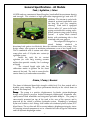
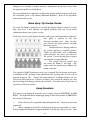
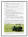
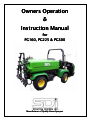
Owners Operation
&
Instruction Manual
for
PG160, PG225 & PG300
Manufacturer of Quality Power Sprayers
Congratulations on your decision to purchase a SDI sprayer. SDI has
been manufacturing a full line of quality sprayers since 1982.
We take great pride in our products and we make sure our sprayers
work properly when they leave the factory. Each sprayer is assembled and
tested prior to shipment. We make every effort to insure that reassembly in
the field and the addition of optional accessories is done properly.
If you have any problems with the assembly or operation of your
new sprayer, please call our Customer Service Department at 559-SDI-5555
between the hours of 7:00 am and 4:00 pm, Pacific Time.
Table of Contents
General Specifications
1
Safety Data
3
Decals
4
Control Identification
5
Pre-Operation Checks
6
System Dynamics
11
Getting Started
14
Pressure Adjustment
14
Metered Bypass Adjustment
15
Tip Overlap Check
16
Spray Operation
16
Troubleshooting
19
Clean Up
21
Winterizing
22
-2-
General Specifications - All Models
Tank / Agitation / Color:
All SDI tanks are constructed from fiberglass, hand rolled for maximum density
and strength. The exterior is a high-gloss color impregnated gel coat with UV
inhibitor. The interior is sealed with
chemical resistant isophthalic resin
for long life and easy complete
cleaning. Each tank is equipped
with an offset 16" screw-in lid with
spring-assisted bullet venting and cpillow perimeter ring gasket sealing
system. A nylon mesh strainer
basket with reinforcing ribs is also
standard with your sprayer.
The unique SDI design has a
raised
bottom
attached
to
directional side gutters to effectively direct the solution to the rear sump. This
design allows your sprayer to maintain performance even at low liquid levels.
This is combined with a custom anti-vortex
sump plate and a V-6 hydro mix venturi-jet
agitation system.
Inside the tank, the six venturi
agitation jets with long wearing ceramic
orifice discs provide a steady 3 to 1 exchange
of liquid.
The external liquid sight tube has
calibration marks in gallons on the front
corner of the tank. The tank is secured to the
carrier frame by 4 tank anchor assemblies.
Frame / Pump / Booms:
The frame is fabricated from high strength welded steel. It is then coated with a
durable epoxy coating. The sprayer pin-mounts directly to the vehicle frame in
place of the dump box.
Pump: The pump is a positive displacement, 3-cylinder, piston-diaphragm
design with positive pressure backed desmopan diaphragms, aluminum case,
epoxy-coated fluid manifolds and integrated pulsation damper. The pump is
conveniently mounted on top of the tank at the rear of the sprayer and is
powered by the vehicle’s auxiliary hydraulic system. Plumbing is reinforced
nylon and stainless steel fittings with rubber or reinforced plastic/nylon/PVC
blend hoses. The see-thru oil fill/reservoir indicates diaphragm integrity status.
All moving internal components are in a flooded oil bath design for lubrication
and full dynamic diaphragm action.
-1-
Maximum Capacities/Pressure: Up to 30 GPM @ maximum vehicle hydraulic
output capacity. Up to 200 PSI maximum system pressure developed at relief
valve pressure gauge with the agitation valve closed.
The pumps hydraulic drive system reaches maximum performance with the
vehicle’s engine speed at 3000 RPM. The vehicle operating RPM’s may change
the hydraulic system output which may affect pump speed/output. Factory
settings allow sprayer to operate in the most common vehicle engine RPM/gear
settings for spraying (2-7 MPH). Other extreme spraying requirements may
require minor component adjustment with tips from the factory for best
results/performance. We recommend a maximum operating RPM of 3400.
SDI “Economy” Manual Lift (Equal Flow) Booms:
Our SDI “Economy” wet booms feature all steel support frames with variable
adjustment mounting and height adjustment brackets. The equal-flow design
includes equal length 304SST tubes with nylon end caps, nylon feed saddles with
¾” inlet and ¾” feed hoses. The nozzle bodies are polypropylene, 10 PSI,
diaphragm check assembly, ¼ turn on/off locking cap with gasket and 50 mesh
slotted nylon tip strainer. Test tips are TeeJet 11008VP polymer material
included. Other sizes, styles, etc. are available upon request for additional
charge. Breakaway hinge with forward and reverse action, fold-up for
transportation and adjustable dampening spring are also standard.
SDI OPTIMUM Turf Booms (Standard and Convertible):
Our Optimum booms have precision jig welded nozzle mounts for nozzle
position accuracy. This design keeps all nozzles in perfect alignment versus pipe
supported designs, wet or dry. Direct liquid injection to each nozzle through
precision designed dry style nozzle inserts with 3/4” hoses. This eliminates
dead spots in fluid path as well as product buildup from heavy powder
applications or neglect (failure to rinse after use). Heavy duty breakaway hinge
has swag style cable level anchor system. You have the ability to add 12 volt
actuators for powered boom wing section lift and descent. The ground contour
wheel option allows constant contact “tip to ground” pattern protection
minimum height adjustment. The standard triple nozzle body assemblies
include cap, gasket, slotted strainer, and polymer test tip. Additional nozzles
and adapters are available upon request for additional charge. The convertible
boom features flip-out wing extensions for increased area coverage and
additional spray width. The liquid to the outer wings is controlled thru a
manually operated ball valve.
-2-
Safety Data:
This symbol is a safety warning and appears next to information
which may help keep you and others from being injured.
Personal Protective Equipment:
Personal Protective Equipment (PPE) is required to prevent accidental exposure
or poisoning. Your chemical label has a complete listing of required PPE needed
for that specific material. Some PPE may include;
Spray Suit – Full coverage (arms and legs) – free of rips or tears.
Face Shield – To prevent accidental facial contact with chemicals.
Goggles – To cover eyes or your glasses for better prote
PVC/Nylon Gloves – Protects hands and sleeve openings.
Mask/Respirator – Approved canister type with appropriate filter cartridges for
chemicals being used.
Work Area Safety Recommendations:
•
Fill/Mix and Load Station – area should not be high traffic and should
have run-off containment. DO NOT allow non-spray personnel to enter mix
area. All mixing should be performed with PPE in place.
•
Water Supply – we recommend using anti-back flow protection on fill
hoses and water source outlets. An Air Gap Filler (anti-siphon) is available as an
option.
•
Fill Hose – should never be put into spray tank, you could contaminate
the hose and your water source.
•
Moving Mechanical System Parts – keep hands away from rotating
pump shaft and restrain loose clothing. Use caution around system when in
operation.
•
Broken or Worn Components – follow recommended safety and
repair/maintenance schedules. DO NOT operate without proper safety gear or
if machine is not in proper working order. Proper operation is not only safer but,
it is more economical when you properly apply the desired chemicals at the
correct rate.
•
Record Keeping – proper records showing chemical being used, batch
size, time, date, areas treated, weather conditions, unusual occurrences can
protect you and others should any problem occur after a turf application has
been made.
-3-
•
Licensing – it is recommended that all spray technician operators secure
proper CPA (Certified Pesticide Applicators) license or equivalent. Check your
local regulations.
Warning: SDI strongly recommends that you read and
understand completely, the Operator’s Manual for the specific
truck you mount the sprayer to – be confident and sure of your
skills before operating the truck with the sprayer attached. The
large liquid payload reacts differently during vehicle movement,
than an equal size dry load!
Please Use Caution!
Decals / Serial Tag Locator:
70Decal, Part # 70
-301 – “Caution” - located on the upper
left corner at the rear of the spr
70Decal, Part # 70
-090 - “Warning” – located on the
tank sump.
70Decal, Part # 70
-357 – “SDI Model#/Serial# Tag” - located
on the sprayer’s frame. You will need to provide this
information to your dealer when ordering parts.
-4-
Control Identification:
ECEC
-VM400
ECEC
-VMAFS
MicroTrak MT3403AFS
Raven SCS330 Control
Raven
Control
Ra
ven SCS440 C
ontrol
**Please refer to the individual control manual for detailed descriptions and features for each
model.
-5-
Pre-System Operation Checks:
See your Vehicle’s Operation/Maintenance Manual for specific instructions. SDI
recommends you read it completely. Typical checks: fuel, oil, and tire pressure.
Spray Tank Checks:
•
•
•
•
•
•
•
•
•
Frame hold down hardware – there should be a gap between the bracket
and tank flange, don’t over tighten, tank damage may occur.
Visually inspect the fiberglass spray tank for leaks or cra
Visually inspect sprayer frame for cracks or broken welds.
Check all fasteners for tightness – replace worn items as needed.
Lid and Gasket (Lid Threads) inspect for leaks or warping, wipe off dirt
from threads and gasket. Apply light lubricant to gasket, such as silicone
spray. Check operation of spring-assisted bullet vent in lid center –
remove any debris and clean or replace broken or missing springs (spring
critical to leak-free lid design). Replace any c-pillow perimeter lid gasket
if damage is present. Some repairs can be made with a vulcanizing
adhesive application. Consult the factory for options.
With the lid open and basket removed, visually inspect the inside of the
spray tank for flaking, and residue buildup. Also check the anti-vortex
plate (black circle in sump area) and sump for debris. A blocked or
restricted suction can result in poor performance and pump problems.
Check jet agitator venturi nozzle position – aim as necessary.
Periodically check ceramic orifice discs in venturi nozzles for cracks or
blockages. These problems can lead to reduced agitation and possible
products mixing problems. Replace or clean as needed.
Inspect hoses for rubs, cracks or any damage that could result in a leak of
fluid – repair as needed.
Pump and Power Checks:
CAUTION: Normal vehicle engine RPM operating
range for sprayer use is 2500 to 3400 RPM’s and 1st,
2nd, and 3rd gears in the low range. Consult the
factory if you need to operate the machinery at
settings other than those specified.
•
•
Inspect exterior of pump, drive motor, and
hydraulic supply hoses for damage or leaks that
could cause problems later. Consult manuals for repair options.
With each fill-up of sprayer tank, inspect the pump’s see-thru oil reservoir
for evidence of diaphragm failure. Oil will appear milky or cloudy if one
or more diaphragms has structural damage allowing chemical into the
pumps lubrication environment. Replace damaged diaphragms and
replace oil in pump body with recommended non-detergent oil.
-6-
•
•
•
•
Inspect and clean pump suction strainer screen.
Inspect bowl and gasket – improper gasket seating can result in poor
pump performance. Replace with correct size gasket only! During bowl
replacement, hand tighten only! DO NOT USE ANY TOOLS!
Remove black nylon suction strainer bowl and clean the screen of debris.
20 mesh is factory standard size. Using 40 or finer mesh will require
checking more often for trapped debris in the screen. A plugged mesh can
result in decreased fluid availability to the pump (starved-suction
condition) resulting effects can range from poor output/performance to
the extreme – diaphragm surface ruptures/tears.
Check bottom load 3-way suction ball valve
and turn handle to pump suction (arrow
points up) arrow points to direction of fluid
flow through valve. Arrow to side is off,
arrow pointing down will drain tank
contents. Do not place valve handle in
off or drain position while pump is
running – diaphragm damage may
occur from starved suction environment.
•
Check to see that agitation control valve
is fully open. Turn knob to the left (counter
clockwise) to open. Due to the unique design
of the tank bottom suction and anti-vortex area
– turning the agitation down or off when the
tank is low on gallonage is not necessary. The
tank will pump down to dry with the agitation
fully on.
Spray Boom Checks:
•
•
•
•
•
•
Inspect mounting hardware and support frame for fastener tightness and
worn or broken components. Repair as needed.
With vehicle tires properly inflated and tank ½ full of water, check boom
for level and proper height. See Setup Manual for proper adjustments.
Grease boom hinges (breakaways), be sure and remove any debris (i.e.
grass, sand, dirt, etc.) from greased area on pivot plates. Dirt affects the
proper operation of the breakaways.
For proper boom retraction, adjust the return spring tension to stiffen or
loosen the movement. See Setup Manual for details.
With booms in the down (operational) position, check section level again.
Between sprays, check and clean all boom nozzle assemblies. Inspect
check valve diaphragms for tears or warping, check and clean tips with a
soft nylon tip brush (DO NOT use hard/metal items – tip damage will
occur!). Clean strainer screens and tip gaskets also. Replace worn or
defective items as needed. Proper tip maintenance will result in optimum
performance and pattern development.
-7-
•
Inspect boom tube end caps for cracks or leaks. Repair as needed.
Motorized Valve Control Checks:
•
•
•
•
•
•
•
•
•
•
Check battery connections – alligator clips – for correct polarity hook up.
Check wire fastener screw on clips for tightness. Remove any corrosive
terminal buildup with a mixture of baking soda and white vinegar. Apply
with an old toothbrush. Brush away buildup taking care to protect your
eyes and clothing from acid splashes. USE EXTREME CAUTION during
this cleaning, ALSO – NO SMOKING – flammable hydrogen gas can be
present!
Check control box mount and console wing nuts for tightness. Clean dirty
console with a damp cloth. DO NOT USE solvents or pressure washer.
Check all toggle switches for play and replace as needed. If switches are
rubber booted, check boots for tears and replace worn ones.
Check control console pressure gauge bezel (clear plastic ring which holds
gauge into console). Raised tabs should be at 6 and 12 o’clock positions.
Check back side of console and make sure power and control cable
assemblies are locked into multi-pin connectors. Then replace protective
rubber boots.
Check fuse and rubber boot.
Check plastic pressure gauge tube for kinks, breaks or blockages. To clean
a blocked tube;
1. Put some clean water in the spray tank (2-5 gallons).
2. On back side of console, is a metal tube receiver with 1/8" tube
engaged. Push tube and top of metal coupler with your thumb and
index finger.
3. While holding metal ring in, pull tube out with your other hand.
4. Direct the disengaged tube away from box and face, and allow the
debris to clear from tube.
5. Turn sprayer on and set engine RPM’s to 3000 on truck.
6. If unsuccessful, stop and shut sprayer off.
7. Disengage other end of tube from boom valve inlet.
8. Use OSHA approved rubber tipped air nozzle to force high pressure
air through tube.
9. If still unsuccessful, replace with a new tube and start flushing
procedure again.
Move to rear of sprayer – boom area.
Inspect motorized valve harness connector plugs – they should be tight
against valve body – screw tight – no prongs showing from valves.
Check valve mating joints (seams) for product leakage. If leakage is
detected, tighten nuts on the 4 guide rod bolts and bring valves closer
together. Not too tight – o-rings are in each joint area. If leak persists,
separate valve bodies and replace o-rings with new ones.
-8-
•
•
•
•
•
Check that all horseshoe clips on boom feed barbs and metered by pass
valves are pushed in and secure. Leakage can result if u-clips are not in
place.
Follow boom hoses from each motorized valve to the corresponding boom
section – nylon split-eyelet feed saddle with nylon hose barb adapter
should fit tight against SST tubing. If saddle rotates on tubing (alignment
nipple most likely broken) replace as needed.
Move back to control console – LISTEN carefully as you perform the next
checks.
Push up on pressure adjust toggle switch – servo motor on yellow striped
valve should run. Reverse toggle position and verify motor works in both
directions. Failure – See Troubleshooting Section.
Push master power toggle to on position – now one switch at a time, try
each boom section, in both directions. Verify that the valves are working
in both directions. Failure – See Troubleshooting Section.
Electric Boom Lift Actuators (optional equipment):
•
•
•
•
•
•
For setup and complete instructions, see Boom Lift Owners Manual.
Check both actuator mounting bolts for tightness and for wing down
position parallel to ground position, adjust level to ground with swag
cable anchor eyebolt.
Periodically spray a penetrating lubricant onto pivot points, hinge
bushing assemblies and swag cables.
Check control harness fuse, it should have a 30 amp rating.
Check control console toggle switch for play and proper operation.
Check harness connectors at control box pigtail and each actuator pigtail
hookup.
Foam Marker (optional equipment):
•
•
•
•
•
•
•
For setup and complete instructions, see Foam Marker Owner’s Manual.
Inspect solution tank for leaks or cracks.
Check cap assembly for cracks or leaks.
Check the fuse in control harness, it should
have a 10 amp rating.
Be sure to only use SDI Foam Concentrate,
other
brands
may
cause
adverse
performance.
Activate power switch to left and then right
positions and verify compressor will start up and if container has fluid,
liquid should flow to the blue tube on the corresponding foam generator
cone and foam should start or liquid will drip from outlet steadily.
Τhe foamer uses two solenoids per side. One is for air, the other for
solution. White hoses carry air to system, blue hoses carry solution. Hose
connections are colored coded white or blue, so are the fly nuts and hoses.
-9-
Just match the colors and make sure to get adequate hose on bib contact
before tightening down on fly nut fastener. If system fails to start, check
12 volt power supply first. System is run/tested at the factory prior to
shipping to your dealer for installation. A running system will not foam
with water only – 160:1 ratio (water: concentrate) or similar solution must
be added to the solution tank’s water. SDI foam concentrate is
recommended for best machine performance. We suggest you add the
foam concentrate first then water. Also, the foam solution will go inert in
24-36 hours.
Check supply hose fasteners on boom tubes for proper position, tightness,
and routing. Should not interfere with tips or nozzle check valves – Loom
(black ribbed cover) should run along the top of boom tube fastened with
nylon zip ties.
Check foam generator cone position, it should be at boom wing end and
clear the spray pattern distribution area. Keep the cones out of spray by
tilting up (required for raindrop style tips).
After use, clean the foamer drop tubes.
•
•
•
Hose Reel (optional equipment):
•
•
Check supply hose from pressure side
of pump to swivel inlet on reel drums for cuts,
scrapes, kinks or leaks.
•
Lubricate reel swivel at grease zerk if
so equipped.
•
Check the reel to tank hold down
hardware for tightness. Rubber well nuts and
fender washers should be used with SST bolts.
See Hose Reel Mounting Instructions and fastener use sequence.
If electric rewind, check battery and all power harness connections. A 40
amp circuit breaker should also be part of the electrical hookup.
- 10 -
System Dynamics
How Your System Works and Why they call it a Sprayer:
POWER – The utility vehicle’s auxiliary hydraulics provides fluid to sprayer’s
pump drive motor. The on/off control lever is located on the center control
console. Pull the lever back to activate the auxiliary hydraulics.
Fluid path through sprayer – items 1 through 12:
1. Spray Tank – serves as containment for fluid and as the product mix
chamber – made of fiberglass and resin compound. Unique bottom shape
has a raised bottom attached to directional side gutters to effectively direct
solution to the rear sump. This design allows sprayer to maintain
performance even at low liquid levels. This design also works as damper
(anti-slosh control) for fluid levels with less than a full tank.
2. Anti
Anti-Vortex Plate – located in sump (lowest part of tank interior), it
facilitates complete liquid draining, minimizing pump cavitation (suction
loss or loss of prime).
3. Suction Flange – external hose barb assembly on tank sump area –
connects tank to main suction hose.
4. Suction/Off/Drain “Bottom Load Valve” – large 1½” 3-way ball valve (allin-one design). Arrow on handle points in direction of fluid flow – up
(suction/pump) – side (off) – down (drain). Off allows cleaning of suctions
strainer screen with loaded tank. Pump should only be running when
arrow points up (suction open) – pump diaphragm damage can occur when
valve is off or drain position while running (starved suction conditions).
5. Suction Strainer – filters our particulate matter and debris from supply
tank. Extends pump life and eliminates foreign objects which may disrupt
normal boom or gun operations.
6. Diaphragm Pump – piston/diaphragm design uses desmophan
diaphragms attached to a piston top and supported by trapped oil from
pumps main case. Stainless steel and nylon spring valves control the fluid
during suction and discharge strokes. The pulsation dampener controls the
pulsations of liquid sent to the boom.
7. Pressure Regulator – controls peak allowable pressure to systems
accessories. T-handle turns clockwise to raise system pressure and counter
clockwise to lower system pressure. Once desired pressure is reached
tighten lock nut on base of T-handle to fix the setting. Once system is
charged to set limit an internal spring and seat releases the excess pressure
and fluid for low pressure recirculation back to the tank through the bypass
hose. Use a maximum pressure of 90 PSI for boom spraying. Be sure to
reduce the pressure to less than 100 PSI after using the hose reel. This
keeps the gauge on the control box from damage or failure.
- 11 -
8. Agitat
Agitation
ion Control Gate Valve – controls amount of tank agitation by
amount of liquid through venturi nozzle multiplier orifice. Recommend
you leave full open at all times. No need to close with low tank liquid level.
9. V-6 Jet Agitation – located above the sump channel at the back of the tank.
6 venturi style nozzles with ceramic metering orifice disc multiply the
exiting fluid and disperse materials throughout the solution tank –
hydraulic mixing.
10. Hose Reel – hose holding spool which allows hookup of spray system to
a spray handgun or walking type spray boom. Holds and organizes
supply/spray hose for repeated organized uses.
11. Boom (Boom Controls) – supplies liquid to the motorized valve
assemblies for dispersal through the spray boom.
12. Boom Tubes – SST pipe or ¾” hose with nozzle bodies attached, evenly
distributes spray liquid to target (ground, turf area) with over lapping
pattern. Nozzle bodies are diaphragm check (drip-free) and supply the
nozzle (tips) when liquid pressure exceeds 10 PSI. When boom shuts off,
the diaphragm keeps the tips from dripping products and also allows a
quick air-free (hiss-free) resumption of the spray pattern.
Notes on System Dynamics
Diaphragm Pump Lubrication – internal mechanical components operate in a
flooded oil bath environment – the pumps cylinder diaphragms keep
contaminants/spray solution from entering the oil’s environment. Diaphragms
should be inspected yearly and replaced when wear or abnormalities are
discovered. The case mounted see-thru oil reservoir will be cloudy if spray has
entered the oil’s environment. The pump can handle all materials and run dry
(no solution) without damage as long as you have clear suction. If you replace
the pump diaphragms, replace the pump oil with non-detergent oil to prevent
against excessive foaming. See the pump manual for recommendation of type
and viscosity.
VenturiVenturi-Jet Agitator Nozzles – installed with ceramic metered orifice disc
(long wearing vs. plastic). Long lasting ceramic discs provide stable agitation
flow rates for trouble-free fluid mixing.
Suction Strainer – provides filtering of particulate matter in spray material. The
standard screen mesh size is 20 in SST material. The screen should be cleaned
daily or more often as the need arises.
NonNon-Corrosive
Corrosive Plumbing – all spray plumbing is SST, nylon or PVC or
polypropylene for all liquid handling parts.
- 12 -
System Dynamics – Materials Compatibility
•
SDI’s diaphragm pump is capable of pumping almost any nonflammable
liquid without trouble or damage to the pump. On extremely thick or gritty
suspensions, it is advisable to operate the sprayer with the suction strainer screen
removed. Clogging up the screen can starve the pump and cause premature
diaphragm damage. For materials with high residue, it is advisable to rinse
pump and plumbing as soon as you return to the sprayer fill area. Do not wait
until after a long lunch break – just add a few gallons of clean water to the tank
and run pump for 30 seconds to dilute the previous residue in system.
Avoid heavy, thick dye markers and add dyes into a full mixing tank, not an
empty filling tank. See Troubleshooting Section for scrubbing suggestions.
•
Spray Liquid Viscosity – the addition of certain WP, WDG, EC’s etc. may
cause the viscosity (thickness) of the water to increase. This can sometimes affect
your calibration of the spray nozzle output. Consult chemical supplier for
recommended modifications to your system.
•
Specific Gravity of Sprayed Suspension – water weighs 8.34lbs./gallon
– when you add mix to the water, the weight per gallon will change. The weight
of the finished solution changes the output calibrations of your nozzles. Consult
your TeeJet catalog for recommendations and formulas for adjusting. This step is
very important when using computer controlled rate systems.
- 13 -
Getting Started:
Practice with water – after you have followed all recommendations, it is
advisable to familiarize yourself with the operation of the new truck and sprayer
package. Practicing with plain water before the addition of expensive and
potentially destructive chemical formulas (when miss-applied) can be smart and
cost effective.
Practice and calibrate before you spray dollars away! Know your machine and
its operation.
System Pressure Adjustment:
Pressure adjustment procedures vary by control style.
Set Pump Output Pressure and Agitation - set speed limiter on vehicle’s
throttle to a RPM that corresponds to desired MPH with selected gear and range
of spraying. Open suction valve on sprayer, then pull auxiliary hydraulics lever
on vehicle’s center console.
Go to pump assembly and close all outlet valves (agitation, boom supply,
and hose reel). This
will give the system a
closed loop for proper
setting of the system
pressure
relief.
Adjust relief valve by
loosening lock nut
then turn T-handle to
right
to
increase
(raise) pressure or to
the left to decrease
(lower)
system
pressure shown on
the liquid dampened gauge. Set pressure in closed loop to 90 – 100PSI. This
setting is below the pressure rating for boom components.
Once the system is set to a fixed pressure you can open and set the tank
agitation output. The gate valve will allow a full range of setting by turning the
knob left for more agitation or turn the knob right for less. The maximum
allowable flow is metered by ceramic orifice disc inside the venturi jet nozzles.
System pressure may drop but should remain above the maximum needed for
boom spraying.
- 14 -
12 volt Motorized Boom Valves and
Adjusting the Metered Bypass –
follow the same setup procedures on
pump and relief valve adjustment to
set system pressure to 90 – 100 PSI.
Turn all switches on console box to off
position and hold down on pressure
adjust switch until pressure will go no
lower (motorized regulator in full
bypass/open setting).
Turn all metered bypass knobs on motorized valves to the right until
closed. Push up on pressure adjust switch until the console mounted gauge
reads 40 PSI then stop. Push boom switches 1, 2, and 3 to up/on position then
activate the boom master switch to the up/on position. All three boom sections
should be spraying and console gauge will probably show less than 40 PSI. Use
the pressure adjust switch to raise the boom pressure to 40 PSI. With system at
40 PSI, turn boom switch # 1 switch to off – pressure should rise above 40 PSI.
Move to motorized
valve and open metered
bypass
knob
#1
counterclockwise
until
pressure drops back off to 40
PSI. Position yourself so you
can see the electronic
console’s gauge or have
someone help you by calling
out when you have adjusted
back to 40 PSI. Cycle the # 1
boom switch on and off as
you watch the pressure
gauge reading.
Except for a short
bounce of the gauge’s needle, the final pressure should read 40 PSI. If it is ok,
repeat steps for boom section # 2 and then for boom section # 3. Advanced users
will notice a live boom pressure when console master control is off. Now it is
possible to change speeds and also correct the nozzles output volume/pressure
while the boom sections are off (no more puddles under a stopped boom!).
Remember, as long as the tip size in the boom remains the same as was in during
metered bypass setup, you can run the nozzles in the full pressure range.
Speed compensating computer equipped sprayers can operate in the manual
mode and follow same guidelines as standard motorized adjustment (no metered
bypass to adjust). The controller should be in manual mode to adjust pressure
on the system. Note: computerized systems work on flow, not pressure. These
systems will still show flow rate field if the speed sensor and flow meter are
operational. In auto mode you the output will vary, this is normal. When the
- 15 -
computer is in control, it makes corrective adjustments many times faster than
the operator could even think about.
Pressure adjustment is important to obtain the proper nozzle output based upon
the standards given in the boom calibration formulas. Refer to the operation
manual for your system.
Boom Spray Tip Overlap Checks:
To verify the boom is properly set up and tip/nozzle height is correct, a water
only pass over a dry concrete or asphalt parking area, can reveal much
information about your system’s setup.
With only water in tank, operate machine and spray with boom full on and drive
and apply a pattern to the dry
driveway/parking area. After the first
pass, observe the spray pattern and look
for uneven areas.
Uniform and even drying indicates
the system applying a uniform pattern.
Checks of each nozzle with a calibration
catch container can assist your data on
the system. Uneven drying or wet stripes
can identify overlap problems.
Wet stripes between nozzle tips
can mean the boom is too high – dry
strips under the nozzles may indicate the
boom is too low.
The supplied 11008VP polymer test tips are a tapered flat-fan design and require
a minimum of 30% overlap when mounted on 20" spacing (this is with a tip to
ground height of 20"). Consult the manufacturer’s recommendations for the
style of tip you plan to use. Patterns, overlaps, sizes, materials, droplet size, and
pressure range can change with the tips selected. Test with water if you have no
experience with new nozzles.
Spray Operation:
The sprayer was designed to operate at an engine speed of 2500 RPM’s to 3400
RPM’s. The hydraulic drive diaphragm pump reaches full volume at 3000 RPM’s
on vehicles tachometer.
•
Park vehicle on level ground with parking brake on – truck in neutral and
engine off.
•
Safety equipment should be used during all sprayer operations as a rule.
Safety equipment should be in good condition, with no rips, holes, or tears. Your
- 16 -
spray suit, neoprene/PVC gloves, goggles/face shield and approved breathing
device (respirator).
•
Sprayer mix and load area should not be a high traffic area or visited by
workers who are not properly protected with safety equipment.
•
To open the 16" filler lid, grasp the lateral raised ribs on lid and rotate
counter clockwise.
•
If equipped with an anti-siphon device (air gap filler) for back flow
protection, rotate and lock gooseneck filler into position.
•
Attach water feed hose and slowly turn on water source and bring up to
full stream.
•
We recommend that the strainer basket be left in place and used to strain
all materials being put into the tank.
•
Pump suction strainer should be installed if not already in place. Also,
open the bottom load valve to the pump at this time.
•
Determine amount of spray mix to be used for your application. If
required amount is less than full tank capacity, fill to desired level.
•
If required amount is a full load (tank topped off), then only fill to a ¾
liquid level. This leaves room for adding chemical to be mixed and applied. (The
balance of the fill water will be added later.)
•
Place truck in neutral with parking brake engaged.
•
Start engine according to procedures outlined in Truck Owner’s Manual.
•
Using throttle lock (manual or electric), set engine speed to 2500 RPM’s.
•
On vehicle’s center console – pull auxiliary hydraulics lever back and turn
the pump drive on. If not operating, review the Troubleshooting Section for
ideas.
•
A quick look into the open lid assembly can verify the pump is working
by the movement of the tank contents. The agitation control valve is located with
the pump and relief valve on the back section of the spray tank. Adjust to level
of agitation required as described earlier. **NOTE** if system fails to work as
described, shut auxiliary hydraulics to pump off and check Troubleshooting
Section for possible cures.
•
Once the system is operational, a quick system test should be performed
before adding product to the mix tank.
- 17 -
•
Lower boom wings to the operational position. Be sure area is clear of
non-authorized spray personnel.
•
Turn on Master Boom Control (switch or lever) and adjust pressure to 40
PSI on controller pressure gauge.
•
Check the boom assembly for leaks. Leaks or other damage can occur
from shipping your sprayer. Inspect hose fittings, nozzle assemblies, end caps
and the complete system. Repair and/or re-tape any leaking fittings. STOP all
drips!
•
All nozzles should become active and develop a full pattern. Clean or
repair all non-working assemblies.
•
With your calibration formula completed, tips properly sized for your
application and your operating pressure set, you may now proceed.
•
Restart truck and engage the pump and agitation system.
•
Slowly add the chemical to be applied to the agitating tank water. The
addition of some products, all-at-once, may cause damage by plugging the inline suction strainer screen which can cause a starved suction condition. Product
labels (WP, EC, WDG, etc.) are abrasive in nature and should include extra mix
time in the tank. Prepackaged dissolvable bag types can be difficult to mix
rapidly. The slower dissolve rate of the bag may lead to clogged suction
strainers. Liquid products can mix easier than most dry formulations, but can be
difficult to mix in cold water areas. Consult with your chemical supply rep for
any precautions or mix-it-up suggestions for any unfamiliar products.
**ALERT** TO ALL TEST PILOTS AND MAD SCIENTISTS!
**The mixing of non-compatible materials or formulations not previously tested
by chemical professionals, should be avoided. Volatile “brews” can be damaging
and costly to repair and dispose of. Leave the burden of mix up compatibility to
the people who manufacture and sell the products to you!
**YOUR SPRAYER WARRANTY IS VOIDED IF DAMAGE
OCCURS AS A RESULT OF A MISUSE OF CHEMICALS**
•
Mix times may vary by chemical, load size, water temperature and
operator skill (experience).
•
Normal mix times can be 20 to 30 minutes per tank! This allows enough
time to provide complete particle distribution throughout the complete mixable
liquid in tank.
•
Just because the water is murky and clouded doesn’t mean all the
chemical is completely in suspension. Give it some time!
•
At the completion of mixing phase and when the material is fully
solublized, you are now ready to spray the mix to your turf areas.
•
If machine is equipped with SDI’s Quick Foam Marking System, refer to
Operation’s Manual for application techniques.
•
Be sure to allow enough spray overlap on end nozzle to cover the foam
ball with a dissipating spray. This technique allows for proper pattern overlap
- 18 -
and the water from the spray speeds up the disappearance of the foam from the
turf.
**NOTE** Failure to hit the foam ball with the spray from the end nozzle
could result in an area of turf that is not being treated with your spray.
Troubleshooting:
Cannot get enough pressure:
•
•
•
•
•
•
•
•
•
•
•
Settings exceed pump capacity
Vehicle RPM’s are set too low
Vehicle’s auxiliary hydraulics not working or switched on
Spray tips too large
Tank empty
Hydraulic fluid in system at low level
Bottom load valve on pump suction off or partially closed
Liquid foaming in tank
Suction vacuum leak/crack in hose
Suction strainer screen clogged
Valves improperly set
Operational Checks During Extended Product Applications:
•
Frequently check your control pressure gauge for any change in your
original calibration setting. A rise in the pressure should alert you to a clogged
or partially blocked spray tip. Routine nozzle screen cleanings and use of all
factory standard strainer screens will greatly reduce the chance of this from
happening. Another possible cause for an increase in pressure could be the
increase of engine speed. We recommend the use of a truck governor or throttle
lock set for your desired speed.
•
One last cause for a system pressure increase could be from the increase in
hydraulic oil temperature. As the hydraulic oil’s temperature goes up, the
viscosity gets thinner. Under ideal conditions, the thinner oil can pass through
the hydraulic motor easier which may increase the number of RPM’s. This small
increase can be managed through the use of the pressure adjust feature on the
sprayers boom controls.
•
Pressure loss can also occur during a spray application, loss of engine
speed, loss of a spray tip, or excessive wear on all spray tips can together or
singly to impact the performance of your sprayer. Frequent checks of your
calibration will result in better system performance.
•
The use of SDI’s Motorized Valves with metered bypass can also affect the
system pressure if not properly adjusted. Refer to Motorized Valve adjustment
procedure for more help. The metered bypass affects the system pressure only
when one or more sections are turned off. Loss or gain of pressure should not
occur when all sections are on at once, because metered bypass option in non- 19 -
operational (when valve is on) only bleeds the system bypass during valve shut
down (off position).
•
Another possible cause of pressure loss on the system could be the result
of a clogged suction strainer. Your system uses a self-priming diaphragm pump.
If the suction strainer screen becomes clogged, it restricts the flow of water to the
pump. Under high liquid requirement applications, the output could drop
enough to cause the system to lose pressure. Keep your strainer screen clean and
it will protect your diaphragms too!
•
Also, be sure the strainer bowl is properly tightened with the gasket in
place. An improperly tightened bowl can result in a suction leak which will
result in loss of fluid to the pump (same as getting a crack in a drinking straw –
hard to pull liquid up through the straw to your mouth!).
•
Another pressure loss cause could be the loss of system hydraulic fluid.
This is rare and would require a large fluid loss to affect the PTO speed of the
pump.
•
A possible cause of pressure loss could be that the ceramic discs in the
agitator assembly are missing or damaged.
If any other problems arise, consult your local dealer or contact the factory.
More Operational Checks:
•
If equipped with a speedometer, verify speed occasionally. The use of the
ground speed governor or throttle lock control can maintain ground speed to
keep your application rate on target. Stable speed is one of your necessary
sprayer constants.
•
Boom wing orientation (levelness to the ground) option can assist over
uneven terrain. You should verify a consistent nozzle height during application.
•
During turnarounds while stopped, visually check the tank liquid sight
tube for the amount of spray left in the tank. DO NOT do this operation during
forward movement. Keep your eyes forward to avoid accidents.
•
If using a computerized controller, periodically check the data/rate screen
for proper rate output. If not holding the desired rate, consult the controller
User’s Manual, your local dealer or the factory.
Between Tank Loads (refills):
•
Check vehicle fuel level, fill as needed.
•
Check solution tank on Foam Marker – fill as needed.
•
If using wettable powders or equivalent, check suction strainer and nozzle
tip strainers for possible debris build up. Clean as needed. Avoid costly and
messy “in-field” service of plugged nozzle screens by checking and cleaning
often.
•
Refer to your calibration charts and area measurements to verify your
application coverage is as planned. Make any necessary adjustments to obtain
your correct rate. A 10% error in application rate can cost you hundreds of
- 20 -
dollars in lost time and chemicals, not to mention the possibility of turf grass
damage.
When the Job is Finished / Sprayer Clean-Up:
Sprayers are often neglected during the winter, at the cost of valuable time and
money in the spring to fix cracked or broken fittings, hoses, or pumps that have
seized.
Your sprayer is a long term investment. All sprayers’ components, from tank to
tips, should be checked. Items that need replacement should be listed.
Replacement parts should be purchased during the off-season.
Sprayers should be protected against the harmful effects of snow, rain, sun, and
strong winds. Moisture in the air, whether from snow, rain or soil, corrodes
metal parts of unprotected equipment.
The sun helps reduce moisture in the air, but it also causes damage. Ultraviolet
light softens and weakens rubber materials such as hoses. The best protection
from the environment is to store sprayers in a dry building. Storing sprayers
provides an opportunity to work on them any time during the off-season,
regardless of weather conditions.
Clean Up:
Prior to storage, clean the sprayer thoroughly with a cleaning solution. Which
solution to use will depend on the pesticides used during the season? Always
check the pesticide label for specific cleaning instructions. During cleaning,
follow these general tips:
•
Use a cleaning solution containing 2 pounds of detergent for each 30 – 40
gallons of water. This should be sufficient for removing most pesticides.
•
First, flush the sprayer clean with clean water. Then add the cleaning
solution to the tank. Agitate thoroughly and allow the water/detergent solution
to circulate through the system for several minutes.
•
Remove nozzles and flush the system twice with clean water.
•
Clean nozzle tips and screen in a strong detergent solution or kerosene,
using a soft brush, such as an old toothbrush.
•
Some pesticide combinations may leave a putty type residue in the tank.
Flushing out the residue of such chemicals after each load prevents an
accumulation.
•
If water alone doesn’t dissolve the residue buildup, add Stoddard solvent,
kerosene, or diesel fuel (1 gallon solvent for 25 gallons for water). Allow paste to
dissolve, then agitate and flush. When cleaning tanks which have carried some
phenoxy herbicides, such as esters of 2, 4-d, first rinse the sprayer with clean
water and then rinse with one of the following, in 25 gallons of water:
- 21 -
1 quart of household ammonia
1 pound of baking soda
2 pounds of trisodium phosphate
Circulate this solution and let a small amount flow through the nozzles. Keep
the remainder of the solution in the system overnight, and then pump it out in
the morning.
During the final cleaning, examine the hoses, clamps, connections, no-drip valve,
nozzle tips and screens for needed replacement.
DO NOT USE A PRESSURE WASHER ON YOUR CONTROL BOX!
Winterizing:
After the final cleaning, follow these tips to get the most out of your sprayer’s
life:
•
Remove no-drip valve, nozzle tips, and strainers and dry them
thoroughly. Clean tips with a toothbrush only. Store metal tips in a can of light
oil, such as diesel fuel or kerosene.
•
Store tips constructed of plastic and nylon in a dry place.
•
Make a special effort in storing tips so that the orifices are not damaged by
contacting each other or other parts such as loose screws.
•
Drain water from all parts to prevent freezing. To insure the hoses are
completely drained of water, purge them with compressed air.
•
Pump requires special care – place automotive antifreeze with rust
inhibitor in the pump and other sprayer parts. This also protects against
corrosion and prevents freezing in case all water is not drained
•
Tape or cover all openings, so that insects, dirt and other foreign material
cannot get into system.
•
Check the sprayer for scratched parts. Touch up these areas with paint to
eliminate corrosion.
•
Store sprayer in a clean, dry location within a building. If storage in a
building is not possible, provide some sort of cover.
•
Remove hoses, wipe them clean of oil, and store them inside a building.
DO NOT hang them over a nail or sharp object. This causes a permanent crease
that reduces flow through the hose. Coil hoses around a basket or other large
round object to prevent sharp bends.
P.O. Box 3107 ~ Visalia, Ca 93278-3107 USA
(559) SDI-5555 ~ (559) SDI-5591 Fax
www.sprayingdevices.com
[email protected]
- 22 -