1
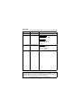
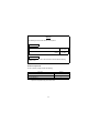
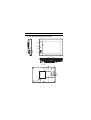
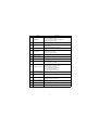
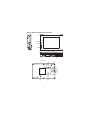
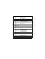
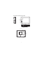
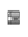
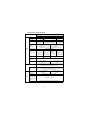
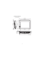
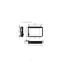
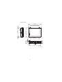
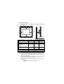
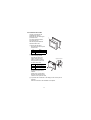
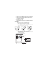
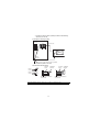
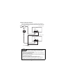
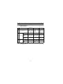
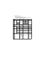
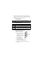
GT15
General Description
GT1585-STBA
GT1575-STBA
GT1575-VTBA
GT1565-VTBA
Thank you for purchasing the GOT1000 Series.
Prior to use, please read both this manual and detailed manual
thoroughly to fully understand the product.
MODEL
GT15-U-HW
MODEL
CODE
1D7M11
IB(NA)-0800305-C(0501)MEE
SAFETY PRECAUTIONS
(Always read these precautions before using this equipment.)
Before using this product, please read this manual and the relevant manuals
introduced in this manual carefully and pay full attention to safety to handle the
product correctly.
The precautions given in this manual are concerned with this product.
In this manual, the safety precautions are ranked as "DANGER" and "CAUTION".
DANGER
Indicates that incorrect handling may cause hazardous
conditions, resulting in death or severe injury.
CAUTION
Indicates that incorrect handling may cause hazardous
conditions, resulting in medium or slight personal
injury or physical damage.
Note that the
caution level may lead to a serious accident according to the
circumstances.
Always follow the instructions of both levels because they are important to
personal safety.
Please save this manual to make it accessible when required and always forward
it to the end user.
A-1
[DESIGN PRECAUTIONS]
DANGER
z Some failures of the GOT, communication unit or cable may keep the outputs
on or off.
An external monitoring circuit should be provided to check for output signals
which may lead to a serious accident.
Not doing so can cause an accident due to false output or malfunction.
z If a communication fault (including cable disconnection) occurs during
monitoring on the GOT, communication between the GOT and PLC CPU is
suspended and the GOT becomes inoperative.
For bus connection : The CPU becomes faulty and the GOT becomes
inoperative.
For other than bus connection : The GOT becomes inoperative.
A system where the GOT is used should be configured to perform any
significant operation to the system by using the switches of a device other
than the GOT on the assumption that a GOT communication fault will occur.
Not doing so can cause an accident due to false output or malfunction.
z Do not use the GOT as the warning device that may cause a serious accident.
An independent and redundant hardware or mechanical interlock is required
to configure the device that displays and outputs serious warning.
Failure to observe this instruction may result in an accident due to incorrect
output or malfunction.
z Incorrect operation of the touch switch(s) may lead to a serious accident if the
GOT backlight is gone out.
When the GOT backlight goes out, the POWER LED flickers (green/orange)
and the display section turns black and causes the monitor screen to appear
blank, while the input of the touch switch(s) remains active.
This may confuse an operator in thinking that the GOT is in “screensaver”
mode, who then tries to release the GOT from this mode by touching the
display section, which may cause a touch switch to operate.
Note that the following occurs on the GOT when the backlight goes out.
z The POWER LED flickers (green/orange) and the monitor screen appears
blank
A-2
[DESIGN PRECAUTIONS]
CAUTION
z Do not bundle the control and communication cables with main-circuit, power
or other wiring.
Run the above cables separately from such wiring and keep them a minimum
of 100mm apart.
Not doing so noise can cause a malfunction.
[MOUNTING PRECAUTIONS]
DANGER
z Be sure to shut off all phases of the external power supply used by the system
before mounting or removing the GOT main unit to/from the panel.
Not doing so can cause the unit to fail or malfunction.
z Be sure to shut off all phases of the external power supply used by the system
before mounting or removing the communication unit, option function board or
multi-color display board onto/from the GOT.
Not doing so can cause the unit to fail or malfunction.
z When installing the multi-color display board, wear an earth band etc. to avoid
the static electricity.
Not doing so can cause a unit corruption.
CAUTION
z Use the GOT in the environment that satisfies the general specifications
described in this manual.
Not doing so can cause an electric shock, fire, malfunction or product damage
or deterioration.
z When mounting the GOT to the control panel, tighten the mounting screws in
the specified torque range.
Undertightening can cause the GOT to drop, short circuit or malfunction.
Overtightening can cause a drop, short circuit or malfunction due to the
damage of the screws or the GOT.
A-3
[MOUNTING PRECAUTIONS]
CAUTION
z When loading the communication unit to the GOT, fit it to the connection
interface of the GOT and tighten the mounting screws in the specified torque
range.
Under tightening can cause the GOT to drop, short circuit or malfunction.
Overtightening can cause a drop, failure or malfunction due to the damage of
the screws or unit.
z When mounting the multi-color display board onto the GOT, tighten the
mounting screws within the specified torque range.
Loose tightening may cause the unit and/or GOT to malfunction due to poor
contact.
Overtightening may damage the screws, unit and/or GOT; they might
malfunction.
z Push the option function board onto the corresponding connector until it
clicks, so that it will be secured firmly.
z Push the multi-color display board onto the corresponding connector so that it
will be secured firmly.
z When inserting a CF card into the GOT, push it into the insertion slot until the
CF card eject button will pop out.
Failure to do so may cause a malfunction due to poor contact.
z When inserting/removing a CF card into/from the GOT, turn the CF card
access switch off in advance.
Failure to do so may corrupt data within the CF card.
z When removing a CF card from the GOT, make sure to support the CF card
by hand, as it may pop out.
Failure to do so may cause the CF card to drop from the GOT and break.
[WIRING PRECAUTIONS]
DANGER
z Be sure to shut off all phases of the external power supply used by the system
before wiring.
Failure to do so may result in an electric shock, product damage or
malfunctions.
A-4
[WIRING PRECAUTIONS]
CAUTION
z Please make sure to ground FG terminal and LG terminal of the GOT power
supply section by applying Class D Grounding (Class 3 Grounding Method) or
higher which is used exclusively for the GOT.
Not doing so may cause an electric shock or malfunction.
z Terminal screws which are not to be used must be tightened always at torque
0.5 to 0.8 N•m.
Otherwise there will be a danger of short circuit against the solderless
terminals.
z Use applicable solderless terminals and tighten them with the specified
torque.
If any solderless spade terminal is used, it may be disconnected
when the terminal screw comes loose, resulting in failure.
z Correctly wire the GOT power supply section after confirming the rated
voltage and terminal arrangement of the product.
Not doing so can cause a fire or failure.
z Tighten the terminal screws of the GOT power supply section in the specified
torque range. Undertightening can cause a short circuit or malfunction.
Overtightening can cause a short circuit or malfunction due to the damage of
the screws or the GOT.
z Exercise care to avoid foreign matter such as chips and wire offcuts entering
the GOT. Not doing so can cause a fire, failure or malfunction.
z Plug the bus connection cable by inserting it into the connector of the
connected unit until it "clicks".
After plugging, check that it has been inserted snugly.
Not doing so can cause a malfunction due to a contact fault.
z Plug the communication cable into the connector of the connected unit and
tighten the mounting and terminal screws in the specified torque range.
Undertightening can cause a short circuit or malfunction.
Overtightening can cause a short circuit or malfunction due to the damage of
the screws or unit.
A-5
[TEST OPERATION PRECAUTIONS]
DANGER
z Before performing the test operations of the user creation monitor screen
(such as turning ON or OFF bit device, changing the word device current
value, changing the settings or current values of the timer or counter, and
changing the buffer memory current value), read through the manual carefully
and make yourself familiar with the operation method.
During test operation, never change the data of the devices which are used to
perform significant operation for the system.
False output or malfunction can cause an accident.
[STARTUP/MAINTENANCE PRECAUTIONS]
DANGER
z When power is on, do not touch the terminals.
Doing so can cause an electric shock or malfunction.
z Connect the battery correctly.
Do not discharge, disassemble, heat, short, solder or throw the battery into
the fire.
Incorrect handling may cause the battery to generate heat, burst or take fire,
resulting in injuries or fires
z Before starting cleaning or terminal screw retightening, always switch off the
power externally in all phases.
Not switching the power off in all phases can cause a unit failure or
malfunction.
Undertightening can cause a short circuit or malfunction.
Overtightening can cause a short circuit or malfunction due to the damage of
the screws or unit.
A-6
[STARTUP/MAINTENANCE PRECAUTIONS]
CAUTION
z Do not disassemble or modify the unit.
Doing so can cause a failure, malfunction, injury or fire.
z Do not touch the conductive and electronic parts of the unit directly.
Doing so can cause a unit malfunction or failure.
z The cables connected to the unit must be run in ducts or clamped.
Not doing so can cause the unit or cable to be damaged due to the dangling,
motion or accidental pulling of the cables or can cause a malfunction due to a
cable connection fault.
z When unplugging the cable connected to the unit, do not hold and pull the
cable portion.
Doing so can cause the unit or cable to be damaged or can cause a
malfunction due to a cable connection fault.
z Do not drop the module or subject it to strong shock. A module damage may
result.
z Do not drop or give an impact to the battery mounted to the unit.
Doing so may damage the battery, causing the battery fluid to leak inside the
battery.
If the battery is dropped or given an impact, dispose of it without using.
[STARTUP/MAINTENANCE PRECAUTIONS]
CAUTION
z Before touching the unit, always touch grounded metals, etc. to discharge
static electricity from human body, etc.
Not doing so can cause the unit to fail or malfunction.
A-7
[BACKLIGHT CHANGING PRECAUTIONS]
DANGER
z Before changing the backlight, always switch off the GOT power externally in
all phases (when the GOT is connected to the bus, the PLC CPU power must
also be switched off externally in all phases) and remove the GOT from the
control panel.
Not switching the power off in all phases may cause an electric shock.
Not removing the unit from the control panel can cause injury due to a drop.
CAUTION
z When replacing the backlight, use the gloves.
Otherwise, it may cause you to be injured.
z Start changing the backlight more than 5 minutes after switching the GOT
power off.
Not doing so can cause a burn due to the heat of the backlight.
[DISPOSAL PRECAUTIONS]
CAUTION
z When disposing of the product, handle it as industrial waste.
[TRANSPORTATION PRECAUTIONS]
CAUTION
z When transporting lithium batteries, make sure to treat them based on the
transport regulations.
(Refer to GT15 User’s Manual for details of the regurated models.)
z Make sure to transport the GOT main unit and/or relevant unit(s) in the
manner they will not be exposed to the impact exceeding the impact
resistance described in the general specifications of the GT15 User's Manual,
as they are precision devices.
Failure to do so may cause the unit to fail.
Check if the unit operates correctly after transportation.
A-8
REVISIONS
* The manual number is noted at the lower right of the top cover.
Print Date
*Manual Number
Revision
Jul., 2004
IB(NA)-0800305-A First edition
Oct., 2004
IB(NA)-0800305-B
Partial correction
Section 3.2, Section 6.3.4
Partial addition
Section 2.1, Section 3.3,
Section 3.4, Section 4.2,
Section 4.3
Jan., 2005
IB(NA)-0800305-C
Parial addition
Section 2.1, Section 2.2,
Section 2.3, Section 3.2,
Section 4.3, Section 5.1
This manual confers no industrial property rights or any rights of any other kind,
nor does it confer any patent licenses. Mitsubishi Electric Corporation cannot be
held responsible for any problems involving industrial property rights which may
occur as a result of using the contents noted in this manual.
© 2004 MITSUBISHI ELECTRIC CORPORATION
A-9
CONTENTS
1. Features ......................................................................................................... 1
2. Part Names .................................................................................................... 2
2.1 Part Names and Settings of the GT1585 ................................................. 2
2.2 Part Names and Settings of the GT1575 ................................................. 4
2.3 Part Names and Settings of the GT1565 ................................................. 6
3. Specifications ................................................................................................. 8
3.1 General Specifications ............................................................................. 8
3.2 Performance Specifications ................................................................... 10
3.3 Power Supply Specifications ................................................................. 13
3.4 External Dimensions .............................................................................. 14
4. Installation .................................................................................................... 17
4.1 Control Panel Inside Dimensions for Mounting GOT ............................. 17
4.2 Panel Cutting Dimensions ..................................................................... 17
4.3 Mounting Position .................................................................................. 18
4.4 Control Panel Inside Temperature and Mounting Angle ........................ 19
4.5 Installation Procedure ............................................................................ 20
5. Wiring ........................................................................................................... 21
5.1 Wiring Precautions ................................................................................ 21
5.2 Power Supply Wiring ............................................................................. 23
5.3 Wiring of Connection Cables ................................................................. 24
5.4 Grouding ................................................................................................ 25
5.5 Power Terminal Connection .................................................................. 27
6. Maintenance and Inspection ........................................................................ 28
6.1 Daily Inspection ..................................................................................... 28
6.2 Periodic Inspection ................................................................................ 29
6.3 Battery Voltage Low Detection and Battery Replacement ..................... 30
6.3.1 Applicable Battery ......................................................................... 30
6.3.2 Battery Specifications ................................................................... 30
6.3.3 Battery Replacement Procedure ................................................... 30
6.3.4 Battery Life .................................................................................... 31
A-10
Manuals
The following shows manuals relevant to this product.
Detailed Manual
Manual Number
(Type code)
Manual name
GT15 User's Manual
(Option)
SH-080528ENG
(1D7M23)
Relevant Manual
For relevant manuals, refer to the PDF manual stored within the drawing
software used.
Product Components
The GOT product package includes the following:
Item name
Quantity
GOT
1
Installation fitting
4
Fixing screw(Plastic)*1
1
*1 Spare for the plastic fixing screw of the GOT.
A-11
1. Features
(1) Improved monitoring performance and connectivity to FA devices
• Using of TFT color liquid crystal display (high intensity, wide angle
view and high definition type) provides clear full-color display and
displays small characters clearly. (Displays digital images of BMP
and other formats in 65536 colors.)
• Provides multi-language display function based on Unicode2.1
True Type font and high-speed drawing of beautiful text.
• High speed monitoring through high speed communication at
maximum of 115.2kbps.
• High speed display and high speed touch switch response.
(2) More efficient GOT operations including screen design, startup,
adjustment, management and maintenance works
• 9MB user memory is included as standard. (Memory capacity can
be expanded up to 57MB by increasing the option memory)
• CF card interface is included as standard
• Font installation is available to increase the system fonts.
• Combined use of 4 types of alarms (system alarm, user alarm list,
alarm history, floating alarm) realizes more efficient alarm notification.
• Maintenance report function is available that measures the backlight energization time and notifies of maintenance time.
(3) Enhanced support of FA device setup tools
• Transferring or monitoring the sequence programs using the personal computer connected to GOT, during direct connection to Q,
QnA, A or FX series PLC CPU, or computer link connection to A,
QnA or Q series (FA Transparent function).
• The USB connector is positioned on the GOT front. This enables
the system startup to be performed more efficiently using FA
device startup tool, and eliminates the necessity of indirect works
(opening and closing the control panel, cable replacement, cable
rewiring) in order to improve the working efficiency.
1
2. Part Names
2.1 Part Names and Settings of the GT1585
16)
2) 3)
1)
4)
14)
6)
5)
GOT Rear face
7)
13)
8)
15)
9)
10)
11)
12)
2
No.
Name
Description
1)
POWER LED
Lit in green: Power is correctly supplied
Lit in orange: Screen saving
Blinks in orange/green: Blown back light bulb
Not lit: Power is not supplied
2)
Display screen
Displays the Utility and the user creation screen.
3)
Touch key
For operating touch switches in the Utility and the user
creation screen
4)
USB interface
For connecting a personal computer
(Connector type: MINI-B)
5)
RS232 interface
For connecting a personal computer, bar code reader or
communicating with PLCs
(Connector type: D sub 9-pin)
6)
Power terminal
Power input terminal, LG terminal, FG terminal
7)
Extension module
interface
For installing a communication module
8)
CF card interface
For installing a CF card
9)
CF card access LED
Lit: CF card accessed
Not lit: CF card not accessed
10)
CF card access switch
Used for stopping the access to the CF card before
removing the CF card from the GOT
ON: CF card being accessed
(CF card removal prohibited)
OFF: CF card not accessed
(CF card removal possible)
11)
Optional function board
interface
For installing the optional function board
12)
Multi-color display board
For installing the multi-color display board
interface
13)
Reset switch
Hardware reset switch
(Inoperative for bus connection)
14)
Hole for unit installation
fitting
Hole for inserting the unit installation fitting
15)
Battery holder
Houses the battery.
16)
Human sensor
Sensor that detects human movement.
3
2.2 Part Names and Settings of the GT1575
2) 3)
1)
4)
14)
5)
6)
GOT rear face
7)
13)
8)
15)
9)
10)
11)
12)
4
No.
Name
Description
1)
POWER LED
Lit in green: Power is correctly supplied
Lit in orange: Screen saving
Blinks in orange/green: Blown back light bulb
Not lit: Power is not supplied
2)
Display screen
Displays the Utility and the user creation screen.
3)
Touch key
For operating touch switches in the Utility and the user
creation screen
4)
USB interface
For connecting a personal computer
(Connector type: MINI-B)
5)
RS232 interface
For connecting a personal computer, bar code reader or
communicating with PLCs
(Connector type: D sub 9-pin)
6)
Power terminal
Power input terminal, LG terminal, FG terminal
7)
Extension module
interface
For installing a communication module
8)
CF card interface
For installing a CF card
9)
CF card access LED
Lit: CF card accessed
Not lit: CF card not accessed
10)
CF card access switch
Used for stopping the access to the CF card before
removing the CF card from the GOT
ON: CF card being accessed
(CF card removal prohibited)
OFF: CF card not accessed
(CF card removal possible)
11)
Optional function board
interface
For installing the optional function board
12)
Multi-color display board
For installing the multi-color display board
interface
13)
Reset switch
Hardware reset switch
(Inoperative for bus connection)
14)
Hole for unit installation
fitting
Hole for inserting the unit installation fitting
15)
Battery holder
Houses the battery.
5
2.3 Part Names and Settings of the GT1565
2) 3)
1)
4)
14)
5)
6)
GOT rear face
7)
13)
8)
9)
10)
15)
11)
12)
6
No.
Name
Description
1)
POWER LED
Lit in green: Power is correctly supplied
Lit in orange: Screen saving
Blinks in orange/green: Blown back light bulb
Not lit: Power is not supplied
2)
Display screen
Displays the Utility and the user creation screen.
3)
Touch key
For operating touch switches in the Utility and the user
creation screen
4)
USB interface
For connecting a personal computer
(Connector type: MINI-B)
5)
RS232 interface
For connecting a personal computer, bar code reader or
communicating with PLCs
(Connector type: D sub 9-pin)
6)
Power terminal
Power input terminal, LG terminal, FG terminal
7)
Extension module
interface
For installing a communication module
8)
CF card interface
For installing a CF card
9)
CF card access LED
Lit: CF card accessed
Not lit: CF card not accessed
10)
CF card access switch
Used for stopping the access to the CF card before
removing the CF card from the GOT
ON: CF card being accessed
(CF card removal prohibited)
OFF: CF card not accessed
(CF card removal possible)
11)
Optional function board
interface
For installing the optional function board
12)
Multi-color display board
For installing the multi-color display board
interface
13)
Reset switch
Hardware reset switch
(Inoperative for bus connection)
14)
Hole for unit installation
fitting
Hole for inserting the unit installation fitting
15)
Battery holder
Houses the battery.
7
3. Specifications
3.1 General Specifications
Item
Specifications
Display
section
0 to 50°C
Operating
ambient
Other than
temperature display
section
0 to 55°C
Storage ambient
temperature
-20 to 60°C
Operating ambient
humidity
10 to 90% RH, non-condensing
Storage ambient
humidity
10 to 90% RH, non-condensing
HalfSweep
amplitude Count
Frequency Acceleration
Vibration resistance*1
Shock resistance
Conforms
to JIS
B3502
and
IEC61131
-2
5 to 9Hz
Under
intermittent
9 to
vibration
150Hz
Under
continuous
vibration
-
3.5mm
9.8m/s2
5 to 9Hz
-
9 to
150Hz
4.9m/s2
10 times
each in X,
1.75mm Y and Z
directions
-
2
Conforms to JIS B3502, IEC 61131-2 (147 m/s , 3 times each in X, Y
and Z directions)
Operating atmosphere
No corrosive gas
Operating altitude*2
2000 m (6562 ft) max.
Installation location
Inside control panel
Overvoltage category*3
II or less
Pollution degree*4
2 or less
Cooling method
Self-cooling
8
*1 When using the MELSECNET/10 communication unit (GT1575J71LP23-Z, GT15-75J71BR13-Z) or CC-Link communication unit
(GT15-75J61BT13-Z), refer to the manual of the communication unit
you use. (Differs with the specification of GOT.)
*2 Do not use or store the GOT under pressure higher than the
atmospheric pressure of altitude 0m (0ft.). Failure to observe this
instruction may cause a malfunction.
*3 This indicates the section of the power supply to which the equipment
is assumed to be connected between the public electrical power
distribution network and the machinery within the premises.
Category II applies to equipment for which electrical power is
supplied from fixed facilities.
The surge voltage withstand level for up to the raged voltage of 300
V is 2500 V.
*4 This index indicates the degree to which conductive material is
generated in the environment where the equipment is used.
In pollution degree 2, only non-conductive pollution occurs but
temporary conductivity may be produced due to condensation.
9
3.2 Performance Specifications
Item
Specifications
GT1585-STBA GT1575-STBA GT1575-VTBA GT1565-VTBA
Type
Screen size
Resolution
Display
section
TFT color liquid crystal
12.1”
10.4”
800 × 600 dots
Display size
246(9.69)(W) ×
184.5(7.26)(H)
[mm](inch)
Display
character
16-dot standard font:
16-dot standard font:
50 characters × 37 lines
40 characters × 30 lines
12-dot standard font:
12-dot standard font:
66 characters × 50 lines
53 characters × 40 lines
211(8.31)(W)
× 158(6.22)(H)[mm](inch)
171(6.73)(W) ×
128(5.04)(H)
[mm](inch)
Display color
256color/65536color*2
Display angle
Left/Right:
Left/Right:
Left/Right:
60 degrees
50 degrees
65 degrees
Left/Right/Top/
Top
:
Top
:
Top
:
Bottom:
40 degrees
35 degrees
50 degrees
85 degrees
Bottom :
Bottom :
Bottom :
50 degrees
45 degrees
60 degrees
*1
Intensity of LCD
only
350 [cd/m2]
280 [cd/m2]
Intensity
adjustment
Life*3
380 [cd/m2]
8-level adjustment
Approx. 41,000 h
Approx. 50,000 h
(Operating ambient temperature (Operating ambient temperature
: 25°C)
: 25°C)
Cold cathode fluorescent tube (replaceable) backlight shutoff
detection function is included.
Backlight off/screen saving time can be set.
Backlight
Life
Number of
touch keys
Key size
Touch
panel
8.4"
640 × 480 dots
Approx. 40,000 h or longer
(Time when display luminance reaches 50% at the operating
ambient temperature of 25°C)
1,900 objects/screen
1,200 objects/screen
(Matrix structure of 38 lines x 50 (Matrix structure of 30 lines x 40
columns)
columns)
Minimum 16 × 16 dots (per key)
Number of
objects that can
be
simultaneously
touched
Life
Maximum of 2 objects
1 million times or more (operating force 0.98N max.)
10
Item
Human
Sensor
Detection
length
1(39.37)
[m](inch)
None
Detection
range
Left/Right/
Top/Bottom:
70 degrees
None
Detection
delay time
0 to 4s
None
C drive
Memory
*4
Specifications
GT1585-STBA GT1575-STBA GT1575-VTBA GT1565-VTBA
Built-in flash memory 9Mbytes (for storing project data and OS)
Life (Number
of write
times)
100,000 times
Battery
GT15-BAT lithium battery (Option)
Backup target
Life
Built-in
interface
Clock data and maintenance time notification data
Approx. 5 years
(Operatomh ambient temperature of 25°C)
RS-232
RS-232, 1ch
Transmission speed :115,200/57,600/38,400/19,200/9,600
/4,800 bps
Connector shape
:D-sub 9-pin (Male)
Application
:PLC communication, bar code reader
connection and PC communication
(Project data upload/download, OS installation, transparent
function)
USB
USB (Full Speed 12Mbps), 1ch
Connector shape : Mini-B
Application
: PC communication (screen data upload/
download, OS installation and FA transparent
function)
CF card
Compact flash slot, 1ch
Connector shape : TYPE I
Application
: Data transfer, data storage
Option function
board
Multi-color
display board
Communication
unit/Option unit
For option function board mounting, 1ch
For multi-color display board mounting, 1ch
For communication unit/option unit mounting, 1ch
Buzzer output
Single tone (tone length adjustable)
Environmental protective
structure
External dimensions
(Excluding USB
environmental protection
cover)
IP67 (JEM1030) (front section) *5
316(12.44)(W)
× 242(9.53)(H)
× 52(2.05)(D)
[mm](inch)
303(11.93)(W) × 214(8.43)(H)
× 49(1.93)(D)[mm](inch)
11
241(9.49)(W) ×
190(7.48)(H)
× 52(2.05)(D)
[mm](inch)
Item
Specifications
GT1585-STBA GT1575-STBA GT1575-VTBA GT1565-VTBA
Panel cutting dimensions
302(11.89)(W)
× 228(8.98)(H)
[mm](inch)
Weight
2.6 kg
(mounting
fixtures are not
included)
Compatible software
package
GT Designer2 Version2.04E or
later
289(11.38)(W)
× 200(7.87)(H)[mm](inch)
2.3 kg
(mounting
fixtures are not
included)
2.2 kg
(mounting
fixtures are not
included)
227(8.94)(W)
× 176(6.93)(H)
[mm](inch)
1.8 kg
(mounting
fixtures are not
included)
GT Designer2 Version2.00A or
later
*1 Bright dots (always lit) and dark dots (unlit) may appear on a liquid
crystal display panel. It is impossible to completely avoid this symptom,
as the liquid crystal display comprises of a great number of display
elements. Please note that these dots appear due to its characteristic
and are not caused by product defect.
*2 Full-color display (66536 colors) is available when the multi-color display
board is mounted.
*3 The GOT screen saving/backlight off function prevents images from
becoming permanently etched on the display screen and increases the
backlight life.
*4 ROM in which new data can be written without deleting the written data.
*5 Compliant with IP67 when the USB environmental protection cover is
attached. Not compliant when a USB cable is connected. Note that this
does not guarantee all users' operation environment.
12
3.3 Power Supply Specifications
Item
Specifications
GT1585-STBA
Input power supply
voltage
GT1575-STBA, GT1575-VTBA, GT1565-VTBA
AC100 to 240V(+10% -15%)
Input frequency
50/60Hz ± 5%
Input max. apparent
power
Power consumption
90VA (maximum load)
28W or less
26W or less
At backlight off
Inrush current
20W or less
45A or less (4ms)
(maximum load)
40A or less (4ms)
(maximum load)
Permissible instantaneous
power failure time
Noise immunity
20ms (100VAC or longer)
By noise simulator of 1,500Vp-p noise voltage, 1µs noise width and
25 to 60Hz noise frequency
Dielectric withstand
voltage
1500VAC for 1 minute across AC external terminals and earth
Insulation resistance
10MΩ or larger by insulation resistance tester
0.75 to 2 [mm2]
Applicable wire size
Applicable solderless
terminal
Solderless terminal for M3 screw RAV1.25-3, V2-S3.3, V2-N3A,
FV2-N3A
Applicable tightening
torque (Terminal block
terminal screw)
0.5 to 0.8 [N•m]
Remarks
Operation at momentary power failure
• If an instantaneous power failure occurs in the power supply and continues
for more than the permissible period, the GOT will be reset.
• Make sure to power on the unit more than 5 seconds after power-off.
13
3.4 External Dimensions
(1) GT1585-STBA
316(12.44)
242(9.53)
10
(0.39)
227(8.94)
10
(0.39)
263(10.35)
52
(2.05)
56
(2.20)
6
(0.24)
5
(0.20)
250(9.84)
301(11.85)
Unit: mm (inch)
14
(2) GT1575-STBA GT1575-VTBA
303 (11.93)
214 (8.43)
10
(0.39)
199 (7.83)
10
(0.39)
252 (9.92)
49
(1.93)
56
(2.20)
6
(0.24)
5
(0.20)
222 (8.74)
288 (11.34)
Unit: mm (inch)
15
(3) GT1565-VTBA
241 (9.49)
190 (7.48)
10
(0.39)
175 (6.89)
10
(0.39)
175.5 (6.91)
52 (2.05)
6
(0.24)
56 (0.20)
5
(0.20)
175.5 (6.91)
226 (8.90)
Unit: mm (inch)
16
4. Installation
4.1 Control Panel Inside Dimensions for Mounting GOT
Mount the GOT onto the control panel while considering the control
panel inside dimensions.
POINT
Applicable cable
Some cables may need to be longer than the specified dimensions
when connecting to the GOT.
Therefore, consider the connector dimensions and bending radius of
the cable as well for installation.
4.2 Panel Cutting Dimensions
Make holes in the panel according to the dimensions list below.
Also, ensure 10mm spaces in upper and lower parts of the panel for
mounting fixtures.
A
* Panel thickness: 2 to 4 mm
or less
B
GOT
17
A [mm](inch)
B [mm](inch)
GT1585
302(11.89)
228(8.98)
(+2(0.08),0(0)) (+2(0.08),0(0))
GT1575
289(11.38)
200(7.87)
(+2(0.08),0(0)) (+2(0.08),0(0))
GT1565
227(8.94)
176(6.93)
(+2(0.08),0(0)) (+2(0.08),0(0))
4.3 Mounting Position
B
When mounting the GOT, the following clearances must be left from the
other device.
D
E
A
C
Panel thickness: 2 to 4mm
(0.08 to 0.16inch)
Type
GT1585
GT1575
GT1565
GOT or Bus connection unit is
fitted
50(1.97) or more 50(1.97) or more 50(1.97) or more
[14(0.55) or more] [31(1.22) or more] [36(1.92) or more]
RS-422 Conversion unit is fitted
51(2.01) or more
68(2.68) or more
73(2.87) or more
Ethernet communication unit,
A MELSECNET/10 communication 50(1.97) or more 50(1.97) or more 50(1.97) or more
unit (coaxial),
[10(0.39) or more] [10(0.39) or more] [10(0.39) or more]
CC-Link communication unit
fitted.
MELSECNET/10 communication 50(1.97) or more 50(1.97) or more 50(1.97) or more
unit (optical) fitted.
[26(1.02) or more] [43(1.69) or more] [48(1.89) or more]
B
80(20) or more
C, D
50(20) or more
E
100(20) or more
Unit: mm (inch)
The values enclosed in parenthesis apply to the case where no other
equipment generating radiated noise (such as a contactor) or heat is
installed. However, keep the ambient temperature of the GOT to 55°C or
lower even in such a case.
The required lead-in allowance for cables may be larger than the size of
A above depending on the unit or cable used.
For the lead-in allowance for cables at the bottom of the GOT, refer to
the following.
Connected manual of GOT1000 series
18
4.4 Control Panel Inside Temperature and Mounting Angle
When mounting the main unit to a control panel or similar, set the display
section as shown below.
• When the temperature inside the control panel is 40 to 55°C or
less, the mounting angle should be in the range 60 to 105
degrees.
GOT
105
Display
section
60
Control panel,
etc.
• The GOT will be deteriorated earlier if it is used at the mounting
angle other than the above. Therefore, the temperature inside the
control panel should be within 40°C.
19
4.5 Installation Procedure
The GOT is designed to be
embedded into a panel.
Mount the GOT by following the
procedure below.
For panel cutting dimensions,
refer to Section 4.2.
Note that the panel thickness
should be within 4mm.
1)
(1) Placing into the panel
Place the GOT into the panel
from the front.
2)
No
Name
1)
GOT
2)
Mounting hole
(2) Fixing the GOT
Insert mounting fixtures
(included with GOT) into
module fixing holes and
tighten mounting screws in
four upper/lower parts until
the GOT will be fixed.
No
Name
1)
Mounting fixture
2)
Mounting screw
Magnified illustration
1)
2)
Tighten mounting screws in
the torque range of 0.36 to
0.48N•m.
(Failure to do so may distort
the panel and make a surface
waviness on the protective sheet.)
(3) A protection film is attached on the display section of GOT prior to
shipment.
Remove the film when the installation is compelted.
20
5. Wiring
5.1 Wiring Precautions
DANGER
z Before starting wiring, always switch off the GOT power externally in all
phases.
Not doing so may cause an electric shock, product damage or malfunction.
CAUTION
z Please make sure to ground FG terminal and LG terminal of the GOT power
supply section by applying Class D Grounding (Class 3 Grounding Method) or
higher which is used exclusively for the GOT.
Not doing so may cause an electric shock or malfunction.
z Correctly wire the GOT power supply section after confirming the rated
voltage and terminal arrangement of the product.
Not doing so can cause a fire or failure.
z Tighten the terminal screws of the GOT power supply section in the specified
torque range. Undertightening can cause a short circuit or malfunction.
Overtightening can cause a short circuit or malfunction due to the damage of
the screws or the GOT.
z Exercise care to avoid foreign matter such as chips and wire offcuts entering
the GOT. Not doing so can cause a fire, failure or malfunction.
This section describes wiring to the GOT power supply section.
For the connection with PLC CPU or others, refer to the following.
GOT1000 Series Connection Manual
Remarks
General preventive measures against noise
There are two kinds of noises: Radiated noise that is transmitted into the air
and conductive noise that is directly transmitted through connected lines. In
noise countermeasures, the both two types of noise should be taken into
account. As the noise countermeasures, there are the following three
methods.
21
(1) Protecting against noise
(a) Keep signal lines away from possible noise sources such as power
cables or high-power driving circuits.
(b) Shield signal lines.
(2) Reducing generated noise
(a) Use a noise filter, etc. to reduce the noise generated from high-power
motor drive circuits.
(3) Releasing noise to the ground
(a) Make sure to connect the ground cable to the ground.
(b) Use a ground cable as short and thick as possible to lower its
impedance.
(c) Separate the grounding between power and control systems.
22
5.2 Power Supply Wiring
• Make wiring connections to the power supply, I/O equipment and
power equipment separately by system as shown below.
When frequent noise is identified, connect an isolation transformer.
Isolation
Main power
GOT power transformer
GOT
T1
I/O power
I/O equipment
Main circuit power
Main circuit equipment
Wiring diagram for power supply
• Twist 100V AC, 200V AC or 24V DC cable as closely as possible
and connect the cable between modules at the minimum length.
Also, use the thickest cable as possible (0.75 to 2mm2) to minimize the voltage drop.
Use M3 solderless terminals and securely tighten them with a
tightening torque of 0.5 to 0.8N•m so that no problem will result.
• Separate the 100V AC, 200V AC or 24V DC cable from the main
circuit lines (high voltage, large current) and/or I/O signal lines.
Keep a distance of 100mm or more.
23
• As measures against surge due to lightning, connect a lightning
surge absorber as shown below.
Lightning surge absorber connection
GOT
I/O equipment
AC
E2
E1
Lightning surge absorber
POINT
1. Separate the grounding of the lightning surge absorber (E1) from
the grounding of the GOT (E2).
2. Select an appropriate lightning surge absorber so that the supply
voltage does not exceed the maximum allowable circuit voltage of
the surge absorber even when it rises to the maximum.
5.3 Wiring of Connection Cables
Keep the connection cables away from the main circuit lines (high
voltage, large current) or I/O signal lines.
When using GT15-C
EXSS-1 or GT15C
grounding in the following steps.
(1) When using GT15-C
BS, perform the
EXSS-1
Not connected
GOT
PLC
3)
FG
LG
N
L
(GT15-C
BS)
OUT
IN
L N LG FG
(GT15-EXCNB)
2SQ cables to
FG terminals,
6)
5) 28cm or less
4)
2)
1)
1) Connect the LG and FG terminals of the terminal block on the GOT
unit power and ground them with a cable.
2) Use the GT15-C
BS's FG cable of 28cm or less.
3) Do not connect the GT15-EXCNB's FG ground cable.
4) Connect the GT15-C
BS's FG cable on the GOT side to FG of the
GOT unit power's terminal block.
24
5) Connect the GT15-C
BS's FG cable on the PLC side to FG of the
PLC's power supply module.
6) Connect the LG and FG terminals of the terminal block on the PLC
and ground them with a cable.
(2) When using GT15-C
BS
For the both side GOTs, connect the LG and FG terminals of the
terminal block on the GOT unit power and ground them with a cable.
5.4 Grouding
Make sure to carry out the followings for grounding.
• Carry out the independent grounding if possible.
• If the independent grounding is impossible, carry out the
shared grounding as shown in fig.2) below.
Other
device
GOT
Other
device
GOT
Grounding
GOT
Other
device
Grounding
(1) Independent ground
...... Best condition
(2) Shared grounding
...... Good condition
(3) Common grounding
...... Not allowed
• Use the cable of 2mm2 or more for grounding.
Set the grounding point closer to the GOT to make the grounding cable short as possible.
(1) Example of independent grounding
Power equipment
(servo, etc.)
PLC
Connection cable
CN1A CN1B
CN 2C N3
FG
LG
FG
FG
LG
GOT
Ground terminal block
Panel
Ground
grounding terminal block
Grounding for
control system
Grounding for power system
25
* Ground the control system, especially modules communicating
each other, to one end.
(2) Example of shared grounding
Power equipment
(servo, etc.)
PLC
Connection cable
CN1A CN1B
FG
LG
CN2C N3
FG
FG
LG
GOT
Panel
grounding
Panel
grounding
Use a short and thick cable as much as possible.
* Ground the system to one end.
Recommended terminal shape
3.2
Terminal
screw
Solderless
terminal
Terminal
screw
Solderless
terminal
6.2mm
or less
3.2
6.2mm
or less
When wiring one cable to
one terminal
When wiring two cables to
one terminal
Applicable solderless terminal RAV1.25- 3, V2- S3.3, V2- N3A, FV2- N3A
26
5.5 Power Terminal Connection
This section provides an example for connecting power cables and
ground cables to the power terminals situated on the back of the GOT.
100/110V AC
In the case of 100V AC
AC
GOT
Fuse
INPUT
100-240VAC
AD
DC
(LG) (FG)
24V DC
In the case of 24V DC
GOT
INPUT
24VDC
(LG) (FG)
Ground cables
Grounding
POINT
1. For 100V AC, 200V AC or 24V DC cable, use the thickest cable as
possible (0.75 to 2mm2) and start twisting them at the position
closest to the connected terminals.
To prevent a short circuit due to loose screws, use the solderless
terminal with insulation sleeve.
2. When connection is made between LG and FG terminals, be sure to
connect them to the ground.
Otherwise, the system becomes susceptible to noise.
Since the LG terminal has potential equal to a half of the input
voltage, touching the terminal may lead to an electric shock.
27
6. Maintenance and Inspection
6.1 Daily Inspection
Daily inspection items
No.
1
2
3
Inspection Item
Usage
status
Criterion
Action
Check for loose Securely
mounting screws. mounted
Retighten screws
within the
specified torque
range.
Loose terminal
screws
Retighten screws
Not loose
with screwdriver
Retighten
terminal screws
Proximate
solderless
terminals
Visual check
Proper intervals
Correct
Loose
connectors
Visual check
Not loose
Retighten
connector fixing
screws
Dirt on protection
Visual check
sheet
Not outstanding
Replace with new
one
Foreign material
attachment
No foreign matter
Remove, clean
sticking
GOT mounting status
Connection
status
Inspection
Method
Visual check
For applicable protective sheet model or replacement procedure, refer to
GT15 User’s Manual.
28
6.2 Periodic Inspection
Yearly or half-yearly inspection items
The following inspection should also be performed when equipment has
been moved or modified or the wiring changed.
No.
1
Inspection Item
Surroun
ding
environ
ment
Ambient
temperature
Ambient
humidity
Atmosphere
2
Power supply voltage
check
3
Mountin
g status
4
Action
0 to 40°C
Make
measurement
Other
0 to 55°C
with thermometer portions
or hygrometer
Measure
10 to 90%RH
corrosive gas
No corrosive gas
For use in
control panel,
temperature
inside control
panel is ambient
temperature
100 to 240VAC
Measure voltage 85AC to 242V
across terminals.
Change supply
power
Move module
Should be mounted
firmly
Retighten
screws
Dirt, foreign
matter
Visual check
No dirt, foreign matter
sticking
Remove, clean
Loose
terminal
screws
Retighten screws
Not loose
with screwdriver
Retighten
terminal screws
Visual check
Proper intervals
Correct
Visual check
Not loose
Retighten
connector fixing
screws
Proximate
Connecti
solderless
on status
terminals
Battery
Criterion
Display
section
Looseness
Loose
connectors
5
Inspection
Method
Check "GOT
internal battery
voltage status" in
"Time setting &
No alarm appears
display" of the
Utility. (Refer to
the GT15 User's
Manual.)
29
Replace with
new battery
when the current
battery has
reached the
specified life
span, even if
battery voltage
low is not
displayed.
6.3 Battery Voltage Low Detection and Battery Replacement
Battery is used to store the current time or maintenance time notification
data.
It is recommended to replace battery periodically.
6.3.1 Applicable Battery
The following battery is applicable for GT15
Model
.
Description
GT15-BAT
Battery for backup of clock data and maintenance time notification data.
6.3.2 Battery Specifications
Item
Specifications
Type
Magnesium manganese dioxide lithium primary battery
Initial voltage
3.0V
Nominal
current
1800mAh
Storage life
Approx.5 years (Operating ambient temperature of 25°C)
Total power
stoppage time
Refer to Section 6.3.4.
Application
For backup of clock data and maintenance time notification data.
6.3.3 Battery Replacement Procedure
Replace battery periodically by
referring to Section 6.3.4 Battery
life.
BATTERY
(1) Keep the GOT power supply
on for 10 minutes or more, and
turn it off.
(Executes step 2 to 6 within 5
minutes of powering the GOT
power supply off.)
Battery holder
(GOT backside)
(2) Remove the battery folder
form the GOT backside.
(3) Remove the old battery from
the folder and disconnect the connector.
(4) Connect the new battery to the connector.
(5) Insert the battery into the folder and set it into the GOT
backside.
30
(6) Turn the GOT power supply on.
(7) Check if the battery condition is normal within the utility.
For details, refer to the GT15 User’s Manual.
POINT
1. Precautions after battery replacement
Make sure to turn on the GOT power supply once upon completion
of battery replacement.
Failure to do so may decrease the battery life.
2. When the bus connection unit (GT15-75ABUSL/GT15-75ABUS2L)
is connected to GT1565
Before installing or replacing the battery, disconnect the bus
connection cable.
(When connecting or disconnecting the bus connection cable, be
sure to power off the GOT and PLC.)
6.3.4 Battery Life
Life span of the battery set in the GOT is shown below.
Battery life
GOT model
Operating ambient
temperature of 0 to
45°C
Operating ambient
temperature of 45 to
55°C
Data backup time after
detection of battery
voltage low*
5 years
3 years
14 days
GT1585
GT1575
GT1565
*: In the following conditions, the data backup time is 5 minutes after the
power supply is turned off.
• The battery connector is disconnected.
• The battery lead is disconnected.
POINT
Battery life and replacement time
1. Battery life reference: Approx.5 years in actual use (Operating
ambient temperature of 25°C)
Battery replacement time reference: 4 to 5 years
Calculate the natural discharge amount of the battery, as necessary.
2. Check if the battery condition is normal within the utility.
For details, refer to the GT15 User’s Manual.
31
MEMO
32
Warranty
Mitsubishi will not be held liable for damage caused by factors found not to be the cause of
Mitsubishi; machine damage or lost profits caused by faults in the Mitsubishi products; damage,
secondary damage, accident compensation caused by special factors unpredictable by
Mitsubishi; damages to products other than Mitsubishi products; and to other duties.
For safe use
• This product has been manufactured as a general-purpose part for general industries, and
has not been designed or manufactured to be incorporated in a device or system used in
purposes related to human life.
• Before using the product for special purposes such as nuclear power, electric power,
aerospace, medicine or passenger movement vehicles, consult with Mitsubishi.
• This product has been manufactured under strict quality control. However, when installing the
product where major accidents or losses could occur if the product fails, install appropriate
backup or failsafe functions in the system.
Country/Region Sales office/Tel
U.S.A
Mitsubishi Electric Automation Inc.
500 Corporate Woods Parkway Vernon
Hills, IL 60061
Tel : +1-847-478-2100
Brazil
MELCO-TEC Rep. Com.e Assessoria
Tecnica Ltda.
Rua Correia Dias, 184,
Edificio Paraiso Trade Center-8 andar
Paraiso, Sao Paulo, SP Brazil
Tel : +55-11-5908-8331
Germany
Mitsubishi Electric Europe B.V. German
Branch
Gothaer Strasse 8 D-40880 Ratingen,
GERMANY
Tel : +49-2102-486-0
U.K
Mitsubishi Electric Europe B.V. UK
Branch
Travellers Lane, Hatfield, Herts., AL10
8XB,UK
Tel : +44-1707-276100
Italy
Mitsubishi Electric Europe B.V. Italian
Branch
Centro Dir. Colleoni, Pal. Perseo-Ingr.2
Via Paracelso 12, 20041 Agrate B.,
Milano, Italy
Tel : +39-039-6053344
Spain
Mitsubishi Electric Europe B.V. Spanish
Branch
Carretera de Rubi 76-80
08190 Sant Cugat del Valles,
Barcelona, Spain
Tel : +34-93-565-3131
France
Mitsubishi Electric Europe B.V. French
Branch
25 Boulevard des Bouvets, F-92741
Nanterre Cedex, France
TEL: +33-1-5568-5568
South Africa
Circuit Breaker Industries LTD.
Tripswitch Drive, Elandsfontein Gauteng,
South Africa
Tel : +27-11-928-2000
Country/Region Sales office/Tel
Hong Kong
Ryoden Automation Ltd.
10th Floor, Manulife Tower, 169 Electric
Road, North Point, HongKong
Tel : +852-2887-8870
China
Ryoden Automation Shanghai Ltd.
3F Block5 Building Automation
Instrumentation Plaza 103 Cao Bao Rd.
Shanghai 200233 China
Tel : +86-21-6120-0808
Taiwan
Setsuyo Enterprise Co., Ltd.
6F., No.105 Wu-Kung 3rd.RD, Wu-Ku
Hsiang, Taipei Hsine, Taiwan
Tel : +886-2-2299-2499
Korea
HAN NEUNG TECHNO CO.,LTD.
1F Dong Seo Game Channel Bldg.,
660-11, Deungchon-dong Kangsec-ku,
Seoul, Korea
Tel : +82-2-3660-9552
Singapore
Mitsubishi Electric Asia Pte, Ltd.
307 Alexandra Road #05-01/02,
Mitsubishi Electric Building
Singapore 159943
Tel : +65-6473-2308
Thailand
F. A. Tech Co.,Ltd.
898/28,29,30 S.V.City Building,Office
Tower 2,Floor 17-18 Rama 3 Road,
Bangkpongpang, Yannawa,
Bangkok 10120
Tel : +66-2-682-6522
Indonesia
P.T. Autoteknindo SUMBER MAKMUR
Jl. Muara Karang Selatan Block a Utara
No.1 Kav. No.11 Kawasan Industri/
Pergudangan Jakarta - Utara 14440
Tel : +62-21-663-0833
India
Messung Systems Put,Ltd.
Electronic Sadan NO:111 Unit No15,
M.I.D.C BHOSARI,PUNE-411026, India
Tel : +91-20-712-2807
Australia
Mitsubishi Electric Australia Pty. Ltd.
348 Victoria Road, PostalBag, No 2,
Rydalmere, N.S.W 2116, Australia
Tel : +61-2-9684-7777
HEAD OFFICE : 1-8-12, OFFICE TOWER Z 14F HARUMI CHUO-KU 104-6212, JAPAN
NAGOYA WORKS : 1-14, YADA-MINAMI 5-CHOME, HIGASHI-KU, NAGOYA, JAPAN
When exported from Japan, this manual does not require application to the Ministry
of Economy, Trade and Industry for service transaction permission.
Specifications subject to change without notice.
Printed in Japan on recycled paper.