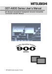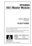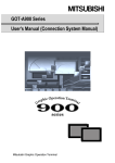
1
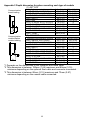
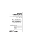
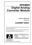
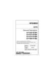
A975GOT-TBA/TBD(-B)
A970GOT-TBA/TBD(-B)
A970GOT-SBA/SBD
A970GOT-LBA/LBD
A960GOT-EBA/EBD
User’s Manual
(Hardware)
Thank you for buying the MELSEC-GOT Series.
Prior to use, please read both this manual and detailed manual
thoroughly and familiarize yourself with the product.
MODEL A900GOT-U-JE
MODEL
1DM100
CODE
IB(NA)-80032-H(0512)MEE
Mitsubishi Graphic Operation Terminal
z SAFETY PRECAUTIONS z
(Read these precautions before using.)
When using this equipment, thoroughly read this manual. Also pay careful
attention to safety and handle the module properly.
These precautions apply only to this equipment.
Refer to the user’s manual of the CPU module to use for a description of the
PLC system safety precautions.
These "Safety Precautions" classify the safety precautions into two categories:
"DANGER" and "CAUTION".
DANGER
CAUTION
Procedures which may lead to a dangerous condition and
cause death or serious injury, if not carried out properly.
Procedures which may lead to a dangerous condition and
cause superficial to medium injury, or physical damage
only, if not carried out properly.
Depending on circumstances, procedures indicated by
CAUTION may also
be linked to serious results.
In any case, it is important to follow the directions for usage.
Store this manual in a safe place so that you can take it out and read it
whenever necessary. Always forward it to the end user.
[DESIGN PRECAUTIONS]
DANGER
z Some failures of the GOT main unit, communication module,
communication board or cable may keep the outputs on or off.
An external monitoring circuit should be provided to check for output
signals which may lead to a serious accident.
Not doing so can cause an accident due to false output or malfunction.
z If a communication fault (including cable disconnection) occurs during
monitoring on the GOT, communication between the GOT and PLC CPU is
suspended and the GOT becomes inoperative.
For bus connection: The CPU becomes faulty and the GOT inoperative.
For other than bus connection: The GOT becomes inoperative.
A system where the GOT is used should be configured to perform any
significant operation to the system by using the switches of a device other
than the GOT on the assumption that a GOT communication fault will
occur.
Not doing so can cause an accident due to false output or malfunction.
A-1
[DESIGN PRECAUTIONS]
DANGER
z Do not use the GOT as the warning device that may cause a serious
accident.
An independent and redundant hardware or mechanical interlock is required
to configure the device that displays and outputs serious warning.
Failure to observe this instruction may result in an accident due to incorrect
output or malfunction.
z Incorrect operation of the touch switch(s) may lead to a serious accident if
the GOT backlight is gone out.
When the GOT backlight goes out, the display section turns black and
causes the monitor screen to appear blank, while the input of the touch
switch(s) still remains active.
This may confuse an operator in thinking that the GOT is in “screensaver”
mode, who then tries to release the GOT from this mode by touching the
display section, which may cause a touch switch to operate.
Note that the following occurs on the GOT when the backlight goes out.
• The monitor screen disappears even when the screensaver is not set.
• The monitor screen will not come back on by touching the display section,
even if the screensaver is set.
CAUTION
z Do not bundle the control and communication cables with main-circuit,
power or other wiring.
Run the above cables separately from such wiring and keep them a
minimum of 100mm apart.
Not doing so noise can cause a malfunction.
[MOUNTING PRECAUTIONS]
DANGER
z Before installing or removing the GOT main unit to or from an enclosure,
always switch off the GOT power externally in all phases.
Not doing so can cause a module failure or malfunction.
z Before loading or unloading the communication board, communication
module, External I/O module or memory board to or from the GOT, always
switch off the GOT power externally in all phases.
Not doing so can cause a module failure or malfunction.
A-2
[MOUNTING PRECAUTIONS]
CAUTION
z The GOT should be used in the environment given in the general
specifications of this user's manual.
Not doing so can cause an electric shock, fire, malfunction or product
damage or deterioration.
z When mounting the GOT main unit to an enclosure, tighten the mounting
screws in the specified torque range.
Undertightening can cause a drop, short circuit or malfunction.
Overtightening can cause a drop, short circuit or malfunction due to the
damage of the screws or module.
z When loading the communication board, communication module or
External I/O module to the GOT main unit, fit it to the connection interface
of the GOT and tighten the mounting screws in the specified torque range.
Undertightening can cause a drop, failure or malfunction.
Overtightening can cause a drop, failure or malfunction due to the damage
of the screws or module.
z When loading the memory board into the GOT main unit, load it into its
corresponding GOT slot and tighten the mounting screws in the specified
torque range.
Undertightening can cause a malfunction due to a contact fault.
Overtightening can cause a malfunction due to the damage of the screws
or module.
z When loading the PC card into the GOT main unit, insert and push it into
its corresponding GOT slot until the PC card eject button comes up.
Not doing so can cause a malfunction due to a contact fault.
z Before loading or unloading the PC card to or from the GOT, set the
memory card access switch to the OFF position.
Not doing so can cause the PC card data to be corrupted.
z Be sure to support the PC card with your hand when removing it.
Otherwise, the PC card may drop, resulting in a failure or damage.
[WIRING PRECAUTIONS]
DANGER
z Before starting wiring, always switch off the GOT power externally in all
phases.
Not doing so may cause an electric shock, product damage or malfunction.
A-3
[WIRING PRECAUTIONS]
CAUTION
z Please make sure to ground FG terminal, LG terminal, and protective
ground terminal of the GOT power supply unit by applying Class D
Grounding (Class 3 Grounding Method) or higher which is used exclusively
for the GOT.
Not doing so may cause an electric shock or malfunction.
z Correctly wire the power supply module on the GOT after confirming the
rated voltage and terminal arrangement of the product.
Not doing so can cause a fire or failure.
z Tighten the terminal screws of the GOT power supply section in the
specified torque range.
Undertightening can cause a short circuit or malfunction.
Overtightening can cause a short circuit or malfunction due to the damage
of the screws or module.
z Exercise care to avoid foreign matter such as chips and wire offcuts
entering the module.
Not doing so can cause a fire, failure or malfunction.
z Plug the bus connection cable by inserting it into the connector of the
connected module until it "clicks".
After plugging, check that it has been inserted snugly.
Not doing so can cause a malfunction due to a contact fault.
z Plug the communication cable into the connector of the connected module
and tighten the mounting and terminal screws in the specified torque
range.
Undertightening can cause a short circuit or malfunction.
Overtightening can cause a short circuit or malfunction due to the damage
of the screws or module.
[TEST OPERATION PRECAUTIONS]
DANGER
z Before performing test operation (bit device on/off, word device's present
value changing, timer/counter's set value and present value changing,
buffer memory's present value changing) for a user-created monitor
screen, system monitoring, special module monitoring or ladder monitoring,
read the manual carefully to fully understand how to operate the
equipment.
During test operation, never change the data of the devices which are used
to perform significant operation for the system.
False output or malfunction can cause an accident.
A-4
[STARTUP/MAINTENANCE PRECAUTIONS]
DANGER
z When power is on, do not touch the terminals.
Doing so can cause an electric shock or malfunction.
z Before starting cleaning or terminal screw retightening, always switch off
the power externally in all phases.
Not switching the power off in all phases can cause a module failure or
malfunction.
Undertightening can cause a short circuit or malfunction.
Overtightening can cause a short circuit or malfunction due to the damage
of the screws or module.
CAUTION
z Do not disassemble or modify the module.
Doing so can cause a failure, malfunction, injury or fire.
z Do not touch the conductive and electronic parts of the module
directly.
Doing so can cause a module malfunction or failure.
z The cables connected to the module must be run in ducts or clamped.
Not doing so can cause the module or cable to be damaged due to the
dangling, motion or accidental pulling of the cables or can cause a
malfunction due to a cable connection fault.
z When unplugging the cable connected to the module, do not hold and pull
the cable portion.
Doing so can cause the module or cable to be damaged or can cause a
malfunction due to a cable connection fault.
A-5
[BACKLIGHT CHANGING PRECAUTIONS]
DANGER
z Before changing the backlight, always switch off the GOT power externally
in all phases (when the GOT is connected to the bus, the PLC CPU power
must also be switched off externally in all phases) and remove the GOT
main unit from the enclosure.
Not switching the power off in all phases may cause an electric shock.
Not removing the unit from the enclosure can cause injury due to a drop.
CAUTION
z While changing the backlight, do not touch the circuit boards and electronic
parts of the GOT.
Doing so can cause a failure or malfunction.
z When changing the backlight, always note the following.
(1) Wear gloves or fingerstalls before starting the replacement of the
backlight.
Not doing so can cause injury.
(2) Start changing the backlight more than 5 minutes after switching the
GOT power off.
Not doing so can cause a burn due to the heat of the backlight.
[DISPOSAL PRECAUTIONS]
DANGER
z When disposing of the product, handle it as industrial waste.
A-6
Revisions
*The manual number is given on the bottom right of the top cover.
Print Date
Jan., 1999
Jun., 1999
*Manual Number
IB(NA)-80032-A
IB(NA)-80032-B
Jun., 2001
IB(NA)-80032-C
Feb., 2002
IB(NA)-80032-D
Jan., 2004
IB(NA)-80032-E
Mar., 2004
IB(NA)-80032-F
Aug., 2004
IB(NA)-80032-G
Dec., 2005
IB(NA)-80032-H
Revision
First edition
Partial correction
Section 5.1
Partial addition
Section 3.2, Section 3.3, Section 5.2
Addition
A970GOT-LBA/LBD
Partial correction
Chapter 2, Section 5.1, Section 5.2, Section 5.3
Addition
Appendix 2
Partial correction
SAFETY PRECAUTIONS
Partial correction
Chapter 1, Section 3.2
Addition
Section 5.4
Partial correction
Section 5.4
MODEL CODE change
Changed from 13JN45 to 1DM100.
Addition
Section 5.4, 5.5, 5.6
Partial correction
Section 5.7 corresponds to the former Section 5.4.
About Manuals, Section 3.3, Appendix 1
Partial correction
Section 3.2
This manual does not warrant or license any industrial property rights and other rights.
Under no circumstances will Mitsubishi Electric be liable or responsible for any
consequential problems involving the industrial property rights which may arise as a
result of the use of this equipment described in this manual.
© 1999 MITSUBISHI ELECTRIC CORPORATION
A-7
CONTENTS
1. Overview .......................................................................................................1
1.1 Packing List ..............................................................................................1
2. System Configuration ....................................................................................2
3. Specifications ................................................................................................3
3.1 General Specifications..............................................................................3
3.2 Performance specifications.......................................................................4
3.3 Power supply specifications......................................................................6
4. Name of the Parts ..........................................................................................7
5. Handling .......................................................................................................8
5.1 Handling instructions ................................................................................8
5.2 Installation method ...................................................................................8
5.3 Wiring diagram .......................................................................................11
5.4 The precautions on the wiring.................................................................12
5.5 Connecting to the GOT Power Section...................................................15
5.6 Connection Cable Wiring ........................................................................16
5.7 Precautions for back light replacement...................................................17
Appendices ....................................................................................................18
Appendix 1 Outline dimension drawing.........................................................18
Appendix 2 Depth dimension for when mounting each type of module.........19
About Manuals
The following manuals are related to this product.
Referring to this list, please order the necessary manuals.
Detailed Manual
Manual name
Manual No.
(Model code)
A985GOT/A975GOT/A970GOT/A960GOT
User’s Manual
(Available as an Option)
SH-4005
(1DM099)
Relevant Manuals
For relevant manuals, refer to the PDF manual stored within the drawing
software.
A-8
1. Overview
This user's manual describes the system configuration, specifications, part
names, handling and outline dimensions of the A975GOT/A970GOT/A960GOT
Graphic operation terminal (Referred to as GOT, hereafter).
The following GOT types are available.
Item
Type
A975GOT-TBA,A975GOT-TBD
A975GOT-TBA-B,A975GOT-TBD-B
A970GOT-TBA,A970GOT-TBD
A970GOT-TBA-B,A970GOT-TBD-B
A970GOT-SBA,A970GOT-SBD
Display section
TFT color liquid crystal
A975GOT
TFT color liquid crystal *1
TFT color liquid crystal
TFT color liquid crystal *1
A970GOT
D-STN color liquid crystal
STN monochrome liquid
A970GOT-LBA,A970GOT-LBD
crystal
A960GOT A960GOT-EBA,A960GOT-EBD
EL
*1:This manual explains the GOT of function version B.
For specifications of GOTs of other function version, refer to A985GOT/
A975GOT/A970GOT/A960GOT User’s Manual.
1.1 Packing List
After unpacking, confirm that you have received the following products.
Product
Quantity
GOT main unit
1
Mounting fixture
4
Communication module securing fixture
3
Caution plate (seal)
1
*1: Affix a caution plate in a conspicuous position such as memory card
interface part. (Affix a caution plate on a communication module during its
use)
When affixing a coution plate on the
communication module
Caution plate
When affixing a coution plate on the
memory card interface
Caution plate
*2: If the protective sheet needs to be replaced, please obtain the one that is to
be purchased separately.
1
2. System Configuration
The overall configuration of the GOT is shown below.
GOT
Drawing software
Communication module, Communication board *1
Option
Memory board
Flash PC card *1
External I/O interface module *1
Backlight
Protective sheet
Debug stand
Others
Audio output device (Commercially available)
Printer (Commercially available) *1
Barcode reader (Commercially available) *1
*1: For details of the system configuration, refer to the GOT-A900 Series User’s
Manual (Connection System Manual).
2
3. Specifications
3.1 General specifications
Item
Operating
ambient
temperature
Storage ambient
temperature
Operating
ambient humidity
Storage ambient
humidity
Vibration
resistance
Shock resistance
Specifications
Display section
0 to 40°C *1
Other than display section
0 to 55°C
-20 to 60°C
10 to 90%RH, non-condensing
10 to 90%RH, non-condensing
Frequency Acceleration Amplitude Sweep Count
0.075mm
⎯
Conforms In case of 10 to 57Hz
10 times in
intermittent
to JIS
57 to
each of X, Y
9.8m/s2
⎯
vibration
B3502
150Hz
and Z
and IEC In case of 10 to 57Hz
directions
0.035mm
⎯
61131-2. continuous
(for 80
57 to
4.9m/s2
⎯
minutes)
vibration
150Hz
Conforms to JIS B3502 and IEC 61131-2
(147m/s2, 3 times in each of X, Y and Z directions)
Operating
atmosphere
Operating
altitude*4
Installation site
Overvoltage
category *2
Contamination
level *3
No corrosive gas
2000m max.
Inside control box
II or less
2 or less
*1: For A975GOT-TBA/TBD (-B) and A970GOT-TBA/TBD (-B), it becomes 0 to
55°C.
*2: Indicates the element in the distribution system between the public
electricity grid and the mechanical equipment inside the premises that the
relevant device is assumed to be connected to.
Category II applies to devices such as those that draw their power supply
from fixed installations.
The surge voltage withstand capability of devices with ratings up to 300V is
2,500V.
*3: This index gives a measure of the incidence of conductive materials in the
environment in which the device is used.
A contamination level of 2 indicates an environment in which there is only
contamination by non-conducting materials, but due to occasional
condensation, conductivity may occur.
*4: Please do not use or store GOT in an environment with atmospheric
pressure greater than the atmospheric pressure at sea level (0m).
There is a possibility errors may occur if this point is not observed.
3
3.2 Performance specifications
Item
Type
Resolution
Display
size
Display Display
section color
Intensity
Display
angle
Backlight
Display
section*2*3
Life*1
Backlight
Touch key
Built-in
memory
Environmental
protective
structure*5
Outline dimensions
Panel cutting
dimensions
Weight
Compatible
software package*4
Specifications
A970GOTSBA
A970GOT-LBA
A970GOT- A970GOT-LBD
SBD
STN
D-STN color
TFT color liquid crystal
monochrome
liquid crystal
liquid crystal
640 × 480 dots
A975GOTTBA(-B)
A975GOTTBD(-B)
A970GOTTBA(-B)
A970GOTTBD(-B)
A960GOT-EBA
A960GOT-EBD
EL
640 × 400 dots
192 (7.57) × 120 (4.73)
211 (8.31) × 158 (6.23) mm (inch)
mm (inch)
2 color
2 color
256 color
16 color
8 color
(monochrome) (yellow orange, black)
TBA/TBD:250 cd/m2
2
250 cd/m
⎯
TBA/TBD-B:380 cd/m2
(LCD only)
(LCD only)
TBA/TBD:80 degrees
50 degrees(right and left),
TBA/TBD-B:85 degrees
45 degrees(up),
⎯
(right, left, up and down)
40 degrees(down)
Cold cathode fluorescent tube backlight
⎯
(Backlight OFF/screen saving time setting allowed)
TBA/TBD:41,000h
50,000h
30,000h
TBA/TBD-B:43,000h
(Operating ambient
(Initial luminance
(Operating ambient
temperature: 25)
70%,25°C)
temperature: 25)
TBA/TBD:40,000h
40,000h
TBA/TBD-B:43,000h
⎯
(Time when display luminance reaches 50% at the
operating ambient temperature of 25°C)
1 million times or more (operating force 100g max.)
Number of write times: 100,000 times
Front section: Equivalent to IP67/NEMA4
Panel inside: IP2X
297 (11.7) (W) × 208 (8.2) (H) × 46 (1.81) (D)
mm (inch)
289 (11.38) (W) × 200 (7.88) (H)
mm (inch)
1.8 (3.96) kg (lb)
1.9 (4.18) kg (lb)
SW0D5C-GTWORKS-E
SW0D5CSW0D5CVersion A or later,
GTWORKS-E GTWORKS-E
SW1D5C-GOTRE-PACK Version A or
Version A or
Version A or later
later,
later,
(The 8-step brightness
SW1D5CSW1D5Cadjustment of the high
GOTREGOTREluminance model is
PACK
PACK
complied to with Version Version A or
Version J or
C and above.)
later
later
268 (10.56) (W) ×
192 (7.56) (H) ×
49 (1.93) (D)
mm (inch)
258 (10.17) (W) ×
183 (7.21) (H)
mm (inch)
1.6 (3.52) kg (lb)
SW0D5CGTWORKS-E
Version A or
later,
SW1D5CGOTREPACK
Version A or
later
*1: When parts must be changed, consult your sales representative.
*2: The screen save and back light OFF functions of the GOT and operator detect sensor
function are used to prevent the display of the screen from being printed and prolong the
service life of the back light.
*3: Bright dots (always lit) and dark dots (unlit) may appear on a liquid crystal display panel. It
is impossible to completely avoid this symptom, as the liquid crystal display comprises of
a great number of display elements.
Please note that these dots appear due to its characteristic and are not caused by
product detect.
4
*4: GT Works2 and GT Designer2, are supported from the first version (Version1.00A).
*5: The specifications differ depending on the version of GOT (hardware version, function
version).
(1) Specification differences by the version of GOT
The specifications of the GOT-A900 series differ depending on the version (hardware
version, function version).
The following shows specification differences of the GOT-A900 series by version.
(a) Environmental protective structure
The environmental protective structure (IP rating) differs depending on the
hardware version of GOT.
Item
Environmental
protective
structure
Front section:
Equivalent to
IP65
Panel inside:
IP2X
Front section:
Equivalent to
IP67/NEMA4
Panel inside:
IP2X
A975GOT-TBA(-B)
A975GOT-TBD(-B)
A970GOT-TBA(-B)
A970GOT-TBD(-B)
Specification
A970GOT-SBA
A970GOT-SBD
A970GOT-LBA
A970GOT-LBD
A960GOT-EBA
A960GOT-EBD
Hardware version A or later
Hardware version N (Dec., 2001) or
later
5
Hardware
version K (Dec.,
2001) or later
3.3 Power supply specifications
Item
Input power supply
voltage
Input frequency [Hz]
Input max. apparent
power
Input max. power
Inrush current
Permissible
instantaneous power
failure time
Noise immunity
Dielectric withstand
voltage
Insulation resistance
Applicable wire size
Applicable solderless
terminal
Applicable tightening
torque (Terminal block
terminal screw)
External output
Specifications
A975GOT-TBA(-B)
A975GOT-TBD(-B)
A970GOT-TBA(-B)
A970GOT-TBD(-B)
A970GOT-SBA
A970GOT-SBD
A970GOT-LBA
A970GOT-LBD
A960GOT-EBA
A960GOT-EBD
100AC to 240V (+10%,-15%)
24VDC(+25%,-20%)
50/60 ± 3
Using 100VAC
Communication board loaded:
50VA or less
Communication module loaded:
60VA or less *1
Using 200VAC
Communication board loaded:
63VA or less
Communication module loaded:
75VA or less *1
40Ap max.
(264VAC, max. load)
-
40W
61Ap max.
(30VDC, max. load)
20ms (100VAC or more)
1ms (19.2VDC or more)
-
By noise simulator of
500Vp-p noise voltage,
1μs noise width and 25 to
60Hz noise frequency
500VAC for 1 minute
1500VAC for 1 minute across AC
across DC external
external terminals and earth
terminals and earth
10MΩ or larger by insulation resistance tester
0.75 to 2mm2
By noise simulator of 1,500Vp-p
noise voltage, 1μs noise width and
25 to 60Hz noise frequency
RAV1.25–3, V2–S3.3, V2-N3A, FV2-N3A
59 to 88Nycm
Refer to *2
*1: When the communication module for bus connection (A9GT-BUSSU/A9GTBUS2SU/A9GT-QBUS2SU) is loaded, this value is equivalent to the input
max. apparent power value when the communication board is loaded.
*2: For external outputs please refer to the A985GOT/A975GOT/A970GOT/
A960GOT User’s Manual that is to be purchased separately.
Remarks
Note that the power is reset if an instantaneous power failure occurs.
However, if the instantaneous power failure is within 20ms when using 100
to 240VAC, or within 1ms when using 24VDC, the operation will be normal.
6
4. Name of the Parts
17)
18) 2)
1)
15)
3) 4)
13) 12)11)
When 9) is removed
14) 16)
17)
17)
No.
Name
1) Display section
2) Reset button
5)
10)
6) 7)
9)
8)
17)
Description
Shows the screen
Used to reset the hardware of the GOT
Used to set the condition of access to the PC card
when it is loaded during power-on (Factory-set to
3) memory card access switch
OFF)
OFF: Access from GOT to PC card inhibited
ON : Access from GOT to PC card enabled
Indicates whether the PC card may be
loaded/unloaded or not
Off: PC card may be loaded/unloaded
4) memory card LED
(When switch 3 is OFF)
On: PC card must not be loaded/unloaded
(When switch 3 is ON)
5) Communication module interface Interface for loading the communication module
6) memory card interface
Interface for loading the PC card
7) memory card ejection button
Button used to withdraw the PC card
8) Speech output terminal
For external speaker connection
9) Slot cover
Fixture to cover the slot
10) Printer interface
For printer connection
For connection of personal computer
11) RS-232C interface
For connecting the bar code reader
12) Option module interface
For option module loading (for future extension)
13) Terminal block
For power input and external output
14) Communication board slot
Slot for communication board loading
15) Memory board slot
Slot for memory board loading
Screw hole for attaching memory
16)
Screw hole used to attach the memory board
board
17) Mounting fixture fitting portion
For mounting fixture fitting
18) Rating plate
⎯⎯⎯⎯
7
5. Handling
5.1 Handling instructions
When mounting the main unit to a control box or the like, set the display section
as shown below.
When the temperature inside the enclosure is 40 to 55°C or less, the mounting
angle should be in the range 60 to 105 degrees.
GOT
105°
Display
section
60°
Enclosure, etc.
The GOT will be deteriorated earlier if it is used at the mounting angle other
than the above. Therefore, the temperature inside the enclosure should be
within 40°C.
Tighten the screws in the following specified range.
Screw Location
Terminal block terminal screw (M3 screw)
Mounting Fixture screw (M4 screw)
Communication module mounting screw (M3 screw)
Communication board mounting screw (M3 screw)
Option module mounting screw (M3 screw)
Case fixing screw (M3 screw)
Memory board mounting screw (M2.6 screw)
RS-232C connector mounting screw
(#4-40 UNC (inch screw))
Tightening Torque Range
59 to 88Nycm
36 to 48Nycm
25 to 35Nycm
20 to 28Nycm
5.2 Installation method
(1) Mounting panel cutting dimensions
When mounting the GOT on a control box door, user-made mounting
base or the like, the door or mounting base must be cut as indicated
below.
Panel opening
B
A
Item
A975GOT
A970GOT
A [mm](inch)
289 (11.39)
[+1.0(0.04), −0(0)]
B [mm](inch)
200 (7.88)
[+1.0(0.04), −0(0)]
A960GOT
258 (10.17)
[+1.0(0.04), −0(0)]
183 (7.21)
[+1.0(0.04), −0(0)]
8
(2) Mounting position
When mounting the GOT, the following clearances must be left from the
other device.
C (80mm (3.15 inch) or more)
D
(100mm
(3.94 inch)
or more)
B
Other
device
(50mm
(1.97inch)
or more)
B
A
(50mm
(1.97inch)
or more)
Plate thickness
within 2mm to 4mm (0.08inch to 0.16inch)
Part A size: As the GOT connection cable is led out downward, the
following clearance must be provided in consideration of the
bending radius.
Item
A [mm] (inch)
A97*GOT + Communication board
130 (5.12) or more
A960GOT + Communication board
140 (5.51) or more
A97*GOT + A9GT-BUSSU/BUS2SU
15 (0.59) or more
A960GOT + A9GT-BUSSU/BUS2SU
30 (1.18) or more
When using a cable prepared by user, please consider the
connector cover to be used and the bending radius of the
cable.
When using a bar code reader, please consider the
dimensions of the connector to be used and the bending
radius of the cable.
Part B size: When using a PC card or an audio output device (for a
connected cable connector and a wire), a clearance of 100
mm (3.94 inch) or more is required. When removing a PC card
by opening a cover of the memory card interface part, a
clearance of 50 mm (1.97 inch) is required. (A clearance of 50
mm (1.97 inch) or more is required when an audio output
device or a memory card is not used.)
(A clearance of 50mm (1.97 inch) or more is required when
these are not used.)
Part C size: Please allow a gap 80mm (3.15inch) or more from the
structure and other equipment in the upper part of the unit to
often allow good ventilation.
Part D size: When installing a device that generates radiation noise
(contactor, etc.) or a device generating high levels of heat near
the GOT, provide a clearance of 100mm (3.94 inch) behind
the module to avoid the effect of the noise and heat.
9
(3) Mounting method
(a) Put the GOT main unit into the panel opening, with its front face first.
(b) Mount the GOT in the following four locations at its top and bottom.
(Top)
(Bottom)
Mounting Position
Mounting position
(c) How to mount and fix the mounting fixture is given below.
1) Insert the mounting fixture into the fixture
fitting portion of the GOT main unit.
2) Tighten and fix the mounting screw in the
specified torque range.
10
5.3 Wiring diagram
(1) 100AC to 240V
INPUT
100-240VAC
RUN OUTPUT
(LG)
(FG)
L
L
12/24VDC 0.1A
+
-
L
L
+ DC12/24V
(2) DC24V
INPUT
24VDC
+
-
INPUT
24VDC
+ -
RUN OUTPUT
(LG)
(FG)
L
L
L
L
12/24VDC 0.1A
+
-
+ DC12/24V
* For application of external outputs of RUN OUTPUT, please refer to
the[A985GOT/A975GOT/A970GOT/A960GOT User’s Manual]
11
5.4 The Precautions on the Wiring
DANGER
z Completely turn off the externally supplied power used in the system when
installing or placing wiring. Not completely turning off all power could result
in electric shock, damage to the product.
CAUTION
z Be sure to ground the FG terminal and LG terminal of the GOT power
supply section to the protective ground conductor. Not doing so could
result in electric shock or erroneous operation.
z When wiring in the GOT power section, be sure that it is done correctly by
checking the product's rated voltage and the terminal layout. Connecting a
power supply that is different from the rating or incorrectly wiring the
product could result in fire or erroneous operation.
z Tighten the terminal screws of the GOT power supply section within the
specified torque range.
If the terminal screws are loose, it could result in short circuits, erroneous
operation or erroneous operation.
Tightening the terminal screws too far may cause damages to the screws
and/or the module, resulting in fallout, short circuits, or erroneous
operation.
z Be sure there are no foreign substances such as sawdust or wiring debris
inside the modle GOT main unit.
y General view of noise countermeasures
There are two types of noise: radiated noise, which is transmitted through
the air, and conducted noise, which is transmitted through a connection
wire. In noise countermeasures, the both two types of noise should be taken
into account. As the noise countermeasures, there are the following three
methods.
(1) Block noise
(a) Keep signal wires away from a possible noise source as power wires
or high-power driving circuits.
(b) Shield signal wires.
(2) Reduce generated noise
(a) Reduce the noise generated from high-power motor drive circuits.
(3) Ground noise without fail
(a) Earth the grounding wire to the ground without fail.
(b) Use a grounding wire as thick and short as possible to ensure low
grounding impedance.
(c) Separate the grounding between power and control systems.
12
(1) Power supply wiring
y Separate the GOT's power supply line from the lines for I/O devices and
power devices as shown below.
When there is much noise, connect an insulation transformer.
Power supply wiring diagram
Main power GOT power Insulation
Transformer
supply
supply
200VAC
GOT
T1
I/O power supply
I/O equipment
Main circuit equipment
Main circuit equipment
y 100VAC, 200VAC and 24VDC wires should be twisted as dense as
possible.
Connect the modules with the shortest distance.
Also, to reduce the voltage drop to the minimum, use the thickest wires
possible (0.75 to 2mm2).
Use a solderless terminal for M3 screw. Also, be sure to tighten the M3
screw within tightening torque 0.55 to 0.88 Nym in order not to cause
trouble.
y Do not bundle the 100VAC, 200VAC and 24VDC wires with, or run them
close to, the main circuit (high voltage, large current) and I/O signal
lines. Reserve a distance of at least 100 mm from adjacent wires.
y As a countermeasure to power surge due to lightening, connect a surge
absorber for lightening as shown below.
Lightening surge absorber connection diagram
GOT
AC
E2
E1
Surge absorber for lightening
POINT
(1) Separate the ground of the surge absorber for lightening (E1) from
that of the GOT (E2).
(2) Select a surge absorber for lightening whose power supply voltage
does no exceed the maximum allowable circuit voltage even at the
time of maximum power supply voltage elevation.
13
(2) Grounding
y For grounding, perform the following:
Use a dedicated grounding wire as far as possible. (Grounding
resistance of 100 or less.)
y When a dedicated grounding cannot be performed, use (2) Common
Grounding shown below.
Also, be sure to take noise countermeasures other than grounding.
Power
equipment
GOT
GOT
Power
equipment
Grounding
(Class 3 grounding)
Grounding
(Class 3 grounding)
(1) Independent grounding
Power
equipment
GOT
Best
(2) Common grounding
Good
(3) Joint grounding
Not allowed
y For grounding a cable, use the cable of 2 mm2 or more.
Position the ground-contact point as closely to the sequencer as
possible, and reduce the length of the grounding cable as much as
possible.
(a) An example of independent grounding
Power equipment
(Servo, etc.)
CN1A CN1B
Connection cable
FG
LG
CN2 CN3
FG
Panel
grounding
FG
LG
Grounding
terminal
block
GOT
Grounding terminal block
Grounding for
control system
Grounding for
power system
* For control system grounding, apply single-point grounding for one
system.
Especially for the devices communicating each other, be sure to
earth the grounding wire at one point.
14
(b) An example of common grounding
Power equipment
(Servo, etc.)
CN1A CN1B
CN2
Connection cable
FG
LG
CN3
FG
GOT
FG
LG
Grounding terminal block
Panel grounding
Use a grounding wire as thick and short as possible.
* Apply single-point grounding for one system.
5.5 Connecting to the GOT Power Section
The following diagram shows the wiring example of power lines, grounding
lines, etc. to the GOT power section.
When using 100VAC
100/110VAC
GOT
AC
INPUT
100-240VAC
Fuse
LG
AC
DC
FG
24VDC
When using 24VDC
GOT
INPUT
24VDC
LG
Grounding wire
Grounding
15
FG
POINT
(1) Use the thickest possible (max. 2 mm2 (14 AWG)) wires for the
100/200 VAC and 24 VDC power cables. Be sure to twist these wires
starting at the connection terminals. To prevent a short-circuit should
any screws loosen, use solderless terminals with insulation sleeves.
(2) When the LG terminals and FG terminals are connected, be sure to
ground the wires. Do not connect the LG terminals and FG terminals
to anything other than ground. If LG terminals and FG terminals are
connected without grounding the wires, the PLC may be susceptible
to noise.
In addition, since the LG terminals have potential, the operator may
receive an electric shock when touching metal parts.
5.6 Connection Cable Wiring
• Do not bind connection cables with the main circuit (high voltage, heavy
current) or I/O signal cables, or lay them close to each other.
• When using A8GT-C EXSS-1 or A8GT-C BS, ground wires as below.
(1) When using A8GT-C EXSS-1 cable
Disconnected
GOT
PLC
3)
FG
LG
N
L
(A8GT-C BS)
OUT
L N LG FG
(A8GT-EXCNB)
6)
5)
IN
2SQ wire FG terminal,
28 cm or less
2)
4)
1)
1) Connect the LG and FG terminals of GOT unit power to the ground
through the terminal block with one wire.
2) Use FG wires of 28 cm or less for the A8GT-C BS cable.
3) Do not connect the FG grounding wire of A8GT-EXCNB cable.
4) Connect the A8GT-C BS cable’s FG wire to FG of the GOT unit power
terminal block.
5) Connect the A8GT-C BS cable’s FG wire on the PLC side to FG of the
PLC power supply module.
6) Connect the LG and FG terminals of the terminal block on the PLC to
ground with one wire.
(2) When using A8GT-C BS cable
Connect the A8GT-C BS cable’s FG wires on the both sides to the FG
terminals on the power terminal block of the both side GOTs.
16
5.7 Precautions for back light replacement
Use the following back lights for the GOT that includes this manual.
Type
Replacement back
light
Model
A975GOT
A970GOT
A975GOT-TBA
(Hardware version D (JAN,1998) or later),
A975GOT-TBD
(Hardware version B (JAN,1998) or later)
A975GOT-TBA-B
(Function version B (JAN,2004) or later),
A975GOT-TBD-B
(Function version B (JAN,2004) or later)
A970GOT-TBA
(Hardware version D (JAN,1998) or later),
A970GOT-TBD
(Hardware version B (JAN,1998) or later)
A970GOT-TBA-B
(Function version B (JAN,2004) or later),
A970GOT-TBD-B
(Function version B (JAN,2004) or later)
A970GOT-SBA, A970GOT-SBD,
A970GOT-LBA, A970GOT-LBD
A9GT-70LTTB
A9GT-70LTTBW
A9GT-70LTTB
A9GT-70LTTBW
A9GT-70LTS
The GOT hardware version and function version can be checked from the
rating plate, which is situated on the backside of the GOT.
GRAPHIC OPERATION TERMINAL
MODEL A970GOT-TBA-B
B
Function version
IN 100-240VAC 50/60Hz
POWER MAX 115VA DATE 0401 AW
0401 AW
C
US LISTED 80M1 IND.CONT.EQ.
MITSUBISHI ELECTRIC CORPORATION
MADE IN JAPAN
BD992C189H02
BACKLIGHT A9GT-70LTTBW
Rating plate
Hardware version
Production date
Conformed standard
Back light model
(The applicable back light model is described.)
The applicable back light differs with the GOT hardware version and function
version.
For more information, refer to A985GOT/A975GOT/A970GOT/A960GOT User’s
Manual.
17
Appendices
L
M
C
K
D
A
I
H
J
G
F
B
G
Appendix 1 Outline dimension drawing
E
Unit: mm(inch)
Item
A
B
C
D
E
F
G
H
I
J
K
L
M
A975GOT, 297 208 235 229 288 199 10
46
40
6
34
31 15.4
A970GOT (11.70) (8.20) (9.26) (9.02) (11.35) (7.84) (0.40) (1.81) (1.58) (0.24) (1.34) (1.22) (0.61)
268 192 204 198 257 182 10
49
43
6
35
32 15.4
A960GOT
(10.56) (7.56) (8.04) (7.80) (10.13) (7.17) (0.40) (1.94) (1.69) (0.24) (1.38) (1.26) (0.61)
18
Appendix 2 Depth dimension for when mounting each type of module
(1) A97*GOT
Communication
board loading
B
A
Communication
module/Option
module loading
B
A
Installed communication module
A9GT-QBUSS, A9GT-BUSS
A9GT-QBUS2S, A9GT-BUS2S
A9GT-BUSSU, A9GT-BUS2SU
A9GT-RS2(T)
A9GT-RS4
A7GT-J71AP23, A7GT-J71LP23
A7GT-J71AR23, A7GT-J71BR13
A7GT-J71AT23B
A8GT-J61BT13, A8GT-J61BT15
A9GT-J71E71-T
A9GT-70KBF
A [mm] (inch) B [mm] (inch)
40 (1.57)
85 (3.35)
62 (2.44)
85 (3.35)
74 (2.91)
15 (0.59)
40 (1.57)
*1
40 (1.57)
115 (4.53)
74 (2.91)
*2
74 (2.91)
*3
96 (3.78)
79 (3.11)
70.2 (2.76)
82.6 (3.25)
-
(2) A960GOT
Installed communication module
A9GT-QBUSS, A9GT-BUSS
A9GT-QBUS2S, A9GT-BUS2S
A9GT-BUSSU, A9GT-BUS2SU
A9GT-RS2(T)
A9GT-RS4
A7GT-J71AP23, A7GT-J71LP23
A7GT-J71AR23, A7GT-J71BR13
A7GT-J71AT23B
A8GT-J61BT13, A8GT-J61BT15
A9GT-J71E71-T
A9GT-70KBF
A [mm] (inch) B [mm] (inch)
43 (1.69)
100 (3.94)
65 (2.56)
100 (3.94)
77 (3.03)
30 (1.18)
43 (1.69)
*1
43 (1.69)
130 (5.12)
77 (3.03)
*2
77 (3.03)
*3
99 (3.90)
82 (3.23)
73.2 (2.88)
85.6 (3.37)
-
*1 Depends on the dimensions of the converter and cable used.
*2 This dimension is between 195mm (7.68) maximum and 80mm (3.15)
minimum depending on the optional fiber cable and connector connected.
*3 This dimension is between 80mm (3.15) maximum and 73mm (2.87)
minimum depending on the coaxial cable connected.
19
MEMO
20
Warranty
Mitsubishi will not be held liable for damage caused by factors found not to be the cause of
Mitsubishi; machine damage or lost profits caused by faults in the Mitsubishi products;
damage, secondary damage, accident compensation caused by special factors
unpredictable by Mitsubishi; damages to products other than Mitsubishi products; and to
other duties.
For safe use
y This product has been manufactured as a general-purpose part for general industries, and
has not been designed or manufactured to be incorporated in a device or system used in
purposes related to human life.
y Before using the product for special purposes such as nuclear power, electric power,
aerospace, medicine or passenger movement vehicles, consult with Mitsubishi.
y This product has been manufactured under strict quality control. However, when installing
the product where major accidents or losses could occur if the product fails, install
appropriate backup or failsafe functions in the system.
Country/Region Sales office/Tel
U.S.A
Mitsubishi Electric Automation Inc.
500 Corporate Woods Parkway Vernon
Hills, IL 60061
Tel : +1-847-478-2100
Brazil
MELCO-TEC Rep. Com.e Assessoria
Tecnica Ltda.
Rua Correia Dias, 184,
Edificio Paraiso Trade Center-8 andar
Paraiso, Sao Paulo, SP Brazil
Tel : +55-11-5908-8331
Germany
Mitsubishi Electric Europe B.V. German
Branch
Gothaer Strasse 8 D-40880 Ratingen,
GERMANY
Tel : +49-2102-486-0
U.K
Mitsubishi Electric Europe B.V. UK
Branch
Travellers Lane, Hatfield, Herts., AL10
8XB,UK
Tel : +44-1707-276100
Italy
Mitsubishi Electric Europe B.V. Italian
Branch
Centro Dir. Colleoni, Pal. Perseo-Ingr.2
Via Paracelso 12, 20041 Agrate B.,
Milano, Italy
Tel : +39-039-6053344
Spain
Mitsubishi Electric Europe B.V. Spanish
Branch
Carretera de Rubi 76-80
08190 Sant Cugat del Valles,
Barcelona, Spain
Tel : +34-93-565-3131
France
Mitsubishi Electric Europe B.V. French
Branch
25 Boulevard des Bouvets, F-92741
Nanterre Cedex, France
TEL: +33-1-5568-5568
South Africa
Circuit Breaker Industries LTD.
Tripswitch Drive, Elandsfontein Gauteng,
South Africa
Tel : +27-11-928-2000
Country/Region Sales office/Tel
Hong Kong
Ryoden Automation Ltd.
10th Floor, Manulife Tower, 169 Electric
Road, North Point, HongKong
Tel : +852-2887-8870
China
Ryoden Automation Shanghai Ltd.
3F Block5 Building Automation
Instrumentation Plaza 103 Cao Bao Rd.
Shanghai 200233 China
Tel : +86-21-6120-0808
Taiwan
Setsuyo Enterprise Co., Ltd.
6F., No.105 Wu-Kung 3rd.RD, Wu-Ku
Hsiang, Taipei Hsine, Taiwan
Tel : +886-2-2299-2499
Korea
HAN NEUNG TECHNO CO.,LTD.
1F Dong Seo Game Channel Bldg.,
660-11, Deungchon-dong Kangsec-ku,
Seoul, Korea
Tel : +82-2-3660-9552
Singapore
Mitsubishi Electric Asia Pte, Ltd.
307 Alexandra Road #05-01/02,
Mitsubishi Electric Building
Singapore 159943
Tel : +65-6473-2308
Thailand
F. A. Tech Co.,Ltd.
898/28,29,30 S.V.City Building,Office
Tower 2,Floor 17-18 Rama 3 Road,
Bangkpongpang, Yannawa,
Bangkok 10120
Tel : +66-2-682-6522
Indonesia
P.T. Autoteknindo SUMBER MAKMUR
Jl. Muara Karang Selatan Block a Utara
No.1 Kav. No.11 Kawasan Industri/
Pergudangan Jakarta - Utara 14440
Tel : +62-21-663-0833
India
Messung Systems Put,Ltd.
Electronic Sadan NO:111 Unit No15,
M.I.D.C BHOSARI,PUNE-411026, India
Tel : +91-20-712-2807
Australia
Mitsubishi Electric Australia Pty. Ltd.
348 Victoria Road, PostalBag, No 2,
Rydalmere, N.S.W 2116, Australia
Tel : +61-2-9684-7777
HEAD OFFICE : TOKYO BUILDING, 2-7-3 MARUNOUCHI, CHIYODA-KU, TOKYO 100-8310, JAPAN
NAGOYA WORKS : 1-14, YADA-MINAMI 5-CHOME, HIGASHI-KU, NAGOYA, JAPAN
When exported from Japan, this manual does not require application to the Ministry
of Economy, Trade and Industry for service transaction permission.
Specifications subject to change without notice.
Printed in Japan on recycled paper.