1
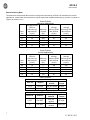
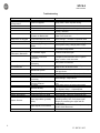
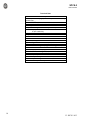
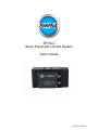
SPCS-2 Servo Pneumatic Control System User’s Guide V1 SPCS-2 8/2013 SPCS-2 User’s Manual Table of Contents Subject Page Warnings & Notice System Setup – Connection Software and Factory Default Setting Load & Velocity Charts Troubleshoot Technical Data 2 3 4, 5, 6 7, 8 9 10 Warnings & Notices WARNING: Installation and operation of electric and high pressure systems (fluids and compressed gas) involves risk including property damage and personal injury or death. Installers and users should be properly trained or certified and take safety precautions. This product may cause death, personal injury, or property damage if improperly used or installed. The information in this document and other information from Bimba Mfg. and its authorized representatives are intended for use by persons having technical expertise in selecting and using these products. Product owners (“you”) should analyze all technical and safety requirements of your specific application, including the consequences of any possible failure, before selecting a product. This product may not be suitable for all applications, such as those acting upon people. Suitability is solely your responsibility. Because the requirements for each application may vary considerably, you are solely responsible for conducting any testing or analysis that may be required to determine the suitability of the product for your application, and to ensure that all performance, safety and warning requirements for your application are met. Caution: While the product is low voltage, it contains open-frame electronic components and care should be taken to prevent un-intentional contact with the product to avoid damage to person or property. Notice: Use and purchase of this product is subject to Bimba Mfg. Terms and Conditions of Sale and Use. Improper installation or use voids warranty. Consult factory regarding special applications. Specifications are subject to change. Reasonable efforts have been made to provide useful and correct information in this document, but this document may contain errors and omissions, and it is subject to change. Contact: Bimba Manufacturing Customer Support 800-44-Bimba or [email protected] or your local Bimba distributor for additional information. Warranty: This product is covered by a 1 year Bimba Mfg. limited warranty. Use without a coalescing filter voids the warranty. Contact Bimba Mfg. or visit website for more details. Notice: Use and purchase of this product is subject to Bimba Manufacturing - Terms and Conditions of Sale and Use. Improper installation or use voids warranty. This product may not be suitable for all applications, such as those acting upon people, and suitability is solely the buyer’s responsibility. Consult factory regarding special applications. 2 V1 SPCS-2 8/13 SPCS-2 User’s Manual System Setup & Connection 1) Download the SPCS-2 setup software from Bimba’s website. Double-click on the file to extract it and follow the instructions displayed on your screen. 2) Connect the SPCS-2 to the Bimba position feedback cylinder using cable SPCS-CBL-FBK 3) Connect the SPCS-2 to your power and command sources using cable SPCS-CBL-PWR-CMD 4) Connect Pneumatic Lines a. Connect port 2 of the SPCS-2 to the back of the cylinder and port 4 to the front as shown in “System Setup” Page 4 (3/8” O.D. tubing – 10’ or less length is recommended to prevent performance loss) b. Inlet air should be dry (-40F dew point) non-lubricated air, non-flammable & non-corrosive dry gases (0.3 micron fine grade coalescing filter with 5 micron pre-filter) at 0-150psig. c. Connect Inlet air to Port 1 5) Connect the valve to your computer using USB cable SPCS2-USB-CBL 6) Troubleshooting a. See “Troubleshooting” Page 9 b. Contact Bimba Mfg. for additional help USB Connector Power/Command & Feedback Connectors 3 V1 SPCS-2 8/13 SPCS-2 User’s Manual Software and Factory Default Setting Basic Settings Screen – Gains Proportional, Derivative, Force Damping, Offset – At startup the default settings are set at zero. After adjustment, if necessary they can be reset to the default value by clicking Initial Setup Screen Communication: Select the Select Port dropdown window: Select a Com Port and click the Enable Communication check box. If communication is established the remaining screen selections will become available. You may have several Com ports from which to choose – you may have to repeat the selection process above to find the correct one. (All selections are “grayed out” until communication is established) Select Input Signal – Command and Feedback by clicking in the appropriate button – 0 to 10V is the default value. Enter cylinder bore size and rod diameter using the up or down arrows. Select Port Communication Click: Save Configuration to SPCS-2 Note: Mouse over “Tool Tips” are provided for each selection 4 V1 SPCS-2 8/13 SPCS-2 User’s Manual Basic Setting Screen Analog Button: Selection allows operation using a rotary potentiometer. PC Slider Button: Selection allows operation by moving the Cylinder Command slider up and down, extending and retracting the cylinder. PC Square Wave Button: Sends a square wave command signal based upon the gain perimeters described below, the minimum/maximum rod positions, ramp up/ramp down and period settings found on the Advance Setting screen. When selected the cylinder will operate using a square way generated by the software. You can adjust the gain, rod position and period perimeters during operation to further understand system responsiveness. Proportional Increase or Decrease the cylinders responsiveness to changes in the command or feedback signal. Lower % slower responsive – Higher % quicker response. Note: If too high system becomes unstable. Suggested starting value 15% (Higher % needed for bore sizes 1-1/16” and below – Lower % needed for bore sizes above 1-1/16”) Gain Settings Derivative Prevents Overshoot – Reduces overshoot and soothes system performance. Too high of a percentage gain can cause overshoot and creep into the target position as well as system instability. Suggested starting value 0. Force Damping Increase or Decrease Force Damping – Increases system stability. Lower % less force damping – Higher % more force damping. Too little force damping can create an oscillating rod condition. Too much force damping can result in a nonresponsive system. Suggested starting value 15%. Offset Offset - Offset is used when the cylinder is mounted vertically to create symmetrical or balanced motion. If the cylinder is facing “rod up”, the offset should be increased. When a cylinder is facing down the offset should be decreased (Negative setting). Value should be set to 0 for horizontal applications. Save your settings Oscillation: If the rod begins a rapid oscillation the Proportional or Force Damping % requires adjustment. To correct this either decrease the Proportional gain or increase Force Damping. 5 V1 SPCS-2 8/13 SPCS-2 User’s Manual Advance Settings Determine the electrical offset % between the Cylinder command signal and the Cylinder feedback signal – o Minimum Position Slide: Move the slide to zero o Maximum Position Slide: Move the slide to 100% o Cylinder Command Slide: Move the slide to zero (the cylinder should fully retract) – note the percentage at the top of the Cylinder Feedback Slide. The percentage shown is the offset that should be adjusted for in setting your command signal to retract the cylinder to a specific position. o Repeat this process with the cylinder fully extended (Move the Cylinder Command to 100%) Note the % difference between the Cylinder Command and the Cylinder Feedback percentages. Use this to compensate for extending the cylinder to a specific position along the rod length. (You may need to add the % offset to the required position when using rod positions other than fully extend and retract) Period – This can only be selected from the Advance screen – This sets the time it takes to complete a full cycle. Minimum Position – Retract; Zero equals full retract; Higher % sets rod retract before full mechanical retract – Ex. 5” rod, set at 35% - rod retract stopping point equals 1.75”. Prevents piston bottoming out at full retract. Maximum Position – Extend; 100% is fully extended. Lower % set maximum extend at less than mechanical full extend – Ex. 5” rod, set at 85% - full rod extension 4.25”. Prevents piston striking the rod guide at full extend. Ramp Up – increases or decreases extend speed. Higher % reduces speed; Lower % increases speed. Ramp Down – increases or decreases retract speed. Higher % reduces speed; Lower % increases speed. When PC Square Wave is selected and the system is operating you can change the perimeters to further adjust the valve and cylinder responsiveness. 6 V1 SPCS-2 8/13 SPCS-2 User’s Manual Maximum Moving Mass The table below recommends the maximum moving mass controlled by a SPCS-2 for horizontal and vertical applications. Actual mass will vary based on cylinder speed and mechanical assembly (e.g. friction in cylinder or system, air pressure, etc.) Bore Size 09 17 31 50 70 Linear Cylinder Horizontal Applications Average Velocity Without Average Overshoot @ Maximum Velocity @ 50% Max Payload Payload Max Payload [in/sec] [lbs.] [in/sec] 20 50 20 10 100 20 15 200 20 15 315 25 15 450 20 Average Velocity @ 25% Max Payload [in/sec] 30 30 30 30 20 Linear Cylinder Vertical Applications Bore Size 09 17 31 50 70 Average Velocity Without Overshoot @ Max Payload [in/sec] 70 70 50 15 20 Maximum Payload [lbs.] 5 10 30 95 135 Average Velocity @ 50% Max Payload [in/sec] 100 60 40 30 20 Rotary Actuator Rack and Pinion - Single Rack Average Bore Size Rotation Velocity 1-1/2” 0 to 360° 150° per second 2” 0 to 360° 150° per second Average Velocity @ 25% Max Payload [in/sec] 100 60 60 30 20 Max Torque 30 in/lb. 84 in/lb. Rack and Pinion - Double Rack Bore Size Rotation 1-1/2” 0 to 360° 2” 0 to 360° Average Velocity 150° per second 150° per second Max Torque 60 in/lb. 144 in/lb. 7 V1 SPCS-2 8/13 SPCS-2 User’s Manual Performance Graphs Horizontal Load Vs Velocity 90 80 Vlocity [in/sec] 70 Bore 60 09 50 17 40 31 30 20 50 10 70 0 0 100 200 300 400 500 Load Veritical Load Vs Velocity 140 Velocity [in/sec] 120 Bore 100 09 80 17 60 31 40 50 20 70 0 0 50 100 150 Load 8 V1 SPCS-2 8/13 SPCS-2 User’s Manual Troubleshooting Symptom Probable Causes Corrective Action System Totally Unresponsive Power not Applied Apply power, check all power wiring Air Off Proportional Gain too Low Pneumatic Connections to Cylinder are Backwards Turn air on Basic Settings – Increase Proportional Gain Initial Setup – Click the “Invert Feedback Sensor Polarity” checkbox Initial Setup – Click the “Transposed” button under Port Connection Proportional Gain too Low Basic Settings – Increase Proportional Gain Force Damping Gain too High Power Supply Voltage not Stable Basic Settings - Decrease Force Damping Inverted Sensor Polarity System Mildly Responsive or Sluggish System Freezes Fully Extended or Retracted System Fails to Operate or is Inaccurate Cylinder too Small Decrease moving mass, increase cylinder size, or increase inlet pressure. No Feedback Signal Connect Feedback Signal Feedback Connected Improperly Verify all wiring is as shown in application examples and as described in the “System Setup” section of this document Cylinder Connected Improperly Verify airline connections Incorrect Wiring Mechanical System Proportional Gain too Low Force Damping Gain too high Offset Gain Adjusted incorrectly Incorrect Cylidner Bore or Rod Diameter Entered Air Leaks SPCS-2 Sticking System Oscillates System Overshoots System ‘Buzzes’ Check power wiring; change power supply Force Damping too Low Proportional Gain too High Proportional Gain too High Input Signal Noise (possibly 60Hz) Input Signals not connected DC Common not connected Verify all wiring is as shown in the System Setup section of this document Insure mechanical system is free from binding and high friction. Basic Settings – Increase Proportional Gain Basic Settings - Decrease Force Damping Basic Settings - Adjust Offset Initial Setup - Check Cylidner Bore and Rod Size Insure there are no air leaks in the system Insure that inlet air meets valve specifications. See “System Setup” – Contact Bimba Basic Settings - Increase Force Damping Basic Settings - Decrease Proportional Gain Basic Settings - Decrease Prportional Gain Verify that large or high power machinery is not operating nearby. Also, verify input signal integrity by examining the signal with an oscilloscope. Verify all wiring as shown in the “System Setup” section of this document Verify all DC common connections 9 V1 SPCS-2 8/13 SPCS-2 User’s Manual Technical Data Mechanical Specifications Pressure: 0 – 150 psig (0 – 10 bar) Un-lubricated, Dry, Neutral Gas Ports: 1/4” NPT Connector: 4-pin M8 x 1 (male) and 3-pin M8 x1 (male) Mounting: 2 x 10-32 thru Holes Temperature Range: 32°F- 104°F (0°C - 40°C) Filtration: 5 µm particulate 0.3µm coalescing Weight: 2.0Lbs. (0.91 kg) Body: Aluminum 6061 Performance Position Accuracy: +- 1% of full stroke Repeatability: 3mV Flow: 46 SCFM @ 80 psig (820 SLPM @ 6 bar) Leak Rate: 12 SCFM @ 150 psig (5.7 SLPM @ 10 bar) Electrical Specifications Power: 24 VDC nominal @ 20W Command Input Impedance: 100kΩ Feedback Input Impedance: 100kΩ Command Input: Configurable 0…10 VDC; 4…20mA Feedback Input: Configurable 0…10 VDC; 4…20mA Excitation: +10V (15mA max) 10 V1 SPCS-2 8/13