1
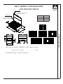
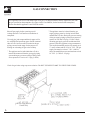
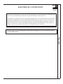
C
US
INSTALLATION
INSTRUCTIONS
JADE SEALED GAS COOKTOP
MODELS:
RJCT30, RJCT36,
RJCT48, RJCT60
PLEASE READ THIS MANUAL COMPLETELY AND CAREFULLY BEFORE PROCEEDING.
NOTE TO THE INSTALLER: Please leave this manual with the cooktop for the consumer.
NOTE TO THE CONSUMER: Please retain this manual for future reference.
IMPORTANT
The installation of this appliance must conform with local codes or, in the absence of
local codes, with the National Fuel Gas Code ANSI Z223.1 – latest edition. If installed in Canada, installation must conform with local codes, or with CAN/CGA
B149.1, Natural Gas Installation Code or CAN/CGA B149.2 Propane Gas Installation Code.
This appliance must be electrically grounded in accordance with local codes or, in
the absence of local codes, with the National Electrical Code, ANSI/NFA 70 – latest
edition. In Canada, it must be electrically grounded in accordance with local codes
or with CSA C22.1 Canadian Electrical Code Part 1.
CONTENTS
Important Safety Instructions ............................................................ 2
Unpacking and Inspection ................................................................. 2
RJCT Model Configuration and Specifications .................................. 3
Clearances from Combustible Surfaces ............................................ 4
Ventilating Hood Recommended Size................................................ 4
Installation Layout ............................................................................. 5
Gas Connection ................................................................................ 6
Electrical Connection ..................................................................... 7-8
Initial Startup and Burner Adjustment ................................................ 9
7355 E. SLAUSON AVENUE, COMMERCE, CALIFORNIA 90040
MADE IN USA
P/N
2400080000
06/03
IMPORTANT SAFETY INSTRUCTIONS
safety
WARNING: If the information in this manual is not followed exactly, a fire or explosion
may result causing property damage, personal injury or death.
- Do not store or use gasoline or other flammable vapors and liquids in the vicinity of this or any other
appliance.
- WHAT TO DO IF YOU SMELL GAS
Do not try to light any appliance.
Do not touch any electrical switch; do not use any phone in the building.
Immediately call your gas supplier from a neighbor’s phone. Follow the gas supplier’s instructions.
If you cannot reach your gas supplier, call the fire department.
Installation and service must be performed by a qualified installer, service agency or the gas supplier.
·
·
·
·
·
Do not use this appliance as a supplement to your furnace/heater. It is not designed to
heat the kitchen or any other room. Using this appliance for other than its intended
use could be dangerous.
UNPACKING AND INSPECTION
Check that the container is upright. Check for
visible damage on the carton. If there is damage on
the carton, contact the carrier, and request an
inspection. Do not refuse shipment but file the
appropriate freight claims. Responsibility for
shipping damage is with the carrier and dealer or
end user.
Cut the shipping straps and carefully lift the carton
up from the cooktop. Check the cooktop for visible
damage.
2
Remove, unwrap and temporarily lay aside any
part or accessory shipped with the unit and make
sure that there are no hardware or accessories left
in the box for accidental disposal. Make sure all
packing material and literature are removed from
the appliance before connecting gas and electrical
supply.
RJCT MODEL CONFIGURATION
AND SPECIFICATIONS
safety
BACK GUARD
(OPTIONAL)
FOR USE WHEN INSTALLED AGAINST
COMBUSTIBLE REAR WALLS
MODEL
ISLAND BACK TRIM
STANDARD
FOR USE ONLY IN PENINSULA
OR ISLAND TYPE INSTALLATION
DIM “A”
RJCT30
30
RJCT36
36
RJCT48
48
2
9 1/2
“A”
1
25 1/2
RJCT3080A
BODY
24
BODY
DEPTH
RJCT3680A
11
9 1/2
RJCT3683A
Safety Instructions
"A"
RJCT3681A
3 1/4
3/4
24
3
6 3/4
RJCT4883A
25
RJCT4881A
ELECTRICAL CHARACTERISTICS: 120v, 1-phase, 60 cycles
Current draw for 12” griddle ......................................... 4 amps
Circuit breaker rating: 10 amp for all models
3
CLEARANCES FROM
COMBUSTIBLE SURFACES:
installation
The Jade Gas Cooktop must be installed in accordance with the minimum clearances as illustrated.
In order to reduce the hazards in reaching over the
appliance, avoid placing cabinets directly above the
cooktop. When installed, the maximum depth of the
overhead cabinets is 13 inches. Note that the
minimum vertical distance between the cooktop
surface and the combustible cabinets above the
cooktop is 50”. If a ventilating hood is used, we
recommend a minimum 30” distance from the
bottom of the hood to the cooktop surface.
Gas Cooktop, A PROFESSIONAL VENTILATING HOOD MUST BE INSTALLED ABOVE
THE APPLIANCE IF THE SPACE “W” IS LESS
THAN 48 INCHES FOR A RJCT36 AND
60 INCHES FOR A RJCT48. Please refer to the
chart for the recommended ventilating hood sizes.
For island installation, the minimum clearances are
12” from rear wall, 6” from side cabinets (18”
above cooking surface).
Because of the high burner input rate of the Jade
Recommended Size
Ventilating Hood
Model
RJCT30
RJCT36
RJCT48
Minimum
Minimum
Vent Hood Size Vent Hood Width
30”
600 CFM
900 CFM
36”
1200 CFM
48”
hood width must be at least the same width
· The
as the cooktop. The hood depth must be 19”
·
·
·
·
minimum.
The hood must not contain combustible
materials.
Due to the high volume ventilation air, a source
of outside replacement air is recommended. This
is particularly important for tightly sealed and
insulated homes.
A qualified heating and ventilating contractor
should be consulted when installing the
ventilating hood and associated duct work.
Any opening in the wall behind the appliance and
in the cabinet top under the appliance must be
sealed.
All dimensions in inches.
All dimensions in inches.
4
INSTALLATION LAYOUT
installation
ANGLE SUPPORT
SUPPLIED WITH APPLIANCE
B
BACK GUARD
OPTIONAL
23
A
SEE DETAIL
ISLAND BACK TRIM
''X''
STANDARD
2
9 1/2
9 1/2
Installation
A
24
SIDE TRIM
SIDE TRIM
MODEL
A
B
DSCT-30
RJCT30
30
29 5/8
DSCT-36
RJCT48
RJCT60
DSCT-48
36
35 5/8
48
46 5/8
COUNTER
TOP
SIDE OF UNIT
5 FT ELECTRICAL CORD
WITH 3-PRONG ANGLED PLUG
CONVERTIBLE
120V/1-PH/60HZ/4AMPS
BUILT-IN
ANGLE SUPPORT
REGULATOR
(SUPPLIED WITH APPLIANCE)
REAR VIEW
3/4 NPT PIPE
(VERITICAL OR HORIZONTAL
(SHOWN WITH OPTIONAL BACK GUARD)
CONNECTION)
DETAIL ''X''
A
25
11
SIDE VIEW
REAR VIEW
PIPE
9 1/2
CORD
3 1/2
1
3/4
24
3
6 3/4
5
GAS CONNECTION
operation
This appliance can be used with natural gas or LP gas. It is shipped from the factory adjusted for use with
the gas specified on the nameplate. (See page 4 of the User Manual, for the location of the nameplate.)
Please note that this appliance is not field convertible.
Shut off gas supply before removing an old
cooktop and leave it off until new installation is
completed.
Use only pipe joint compound that is approved for
use with liquified petroleum gases. Install a manual
shut-off valve in an accessible location in the gas
piping, external to the range for the purpose of
turning on or shutting off gas to the cooktop.
appliance and its individual shut-off valve
· The
must be disconnected from the gas supply piping
appliance must be isolated from the gas
· The
supply piping system by closing its individual
manual shut-off valve during any pressure testing
of the gas supply piping system at test pressures
equal to or less than 1/2 psig (3.5 kPa). Check
incoming gas supply pressure and the manifold
pressure (after the regulator) using a manometer.
The required manifold pressure for natural gas is
5” water column and for LP is 10” W.C. The gas
supply line must be at least 1” W.C. (249 Pa)
above the manifold pressure and must not exceed
14” W.C. (3.5 kPa or 1/2 psig).
system during any pressure testing of that system
at test pressures in excess of 1/2 psig (3.5kPa).
Check for gas leaks using soap-water solution. DO NOT USE OPEN FLAME TO CHECK FOR LEAKS.
(VERTICAL OR HORIZONTAL
CONNECTION)
6
ELECTRICAL CONNECTION
operation
The Jade Gas Cooktop requires a 120 volt, 60 hertz, single phase, individual and properly grounded branch
circuit. The circuit must be protected with a 10 amp circuit breaker or time-delay fuse.
This appliance is equipped with a three-prong (grounding) plug for your protection against shock hazard
and should be plugged directly into a properly grounded three-prong receptacle. Do not cut or remove the
grounding prong from this plug. This appliance must be electrically grounded in accordance with local
codes or, in the absence of local codes with the National Electrical Code ANSI/NFA 70-latest edition. In
Canada, it must be in accordance with CSAC22.1 Canadian Electrical Code Part 1.
Disconnect power before installing the cooktop. Before turning power ON, be sure that the controls
are in the OFF position.
Operation
7
RJCT3080A
RJCT3680A
RJCT3681A
RJCT3683A
RJCT4881A
8
RJCT4883A
INITIAL STARTUP AND ADJUSTMENT
operation
The air for combustion and ventilation is supplied
through the front of the cooktop. The air is
exhausted upward. Do not obstruct the flow of
combustion and ventilation air.
Before startup, make sure that the cooktop has
been carefully checked for gas leaks and that it has
been properly connected to electric power.
Sealed Burners
The burners are tested and adjusted at the factory
prior to shipping cooktop. Adjustment is not
required on burners.
IMPORTANT: It is mandatory that the
ventilating hood, if installed, be turned
on and remain “ON” while burners are
operating.
CHARBROILER
Similar to the open top burners, the
charbroiler uses spark ignition. To light
burner, push knob in, turn knob to HI and then
turn to LITE. To adjust burner flames, turn air
shutters. The burner flames should be blue
with 1/2” high distinct cones. It is normal that
during initial startup and when the knob is set
on HI, the first inch of the ports is not lit.
After the burners have established and
warmed up, the front ports will stay lit.
1/2
GRIDDLE
The griddle uses a glowbar ignition system. To
light the griddle burner, turn power switch on.
Push and turn griddle thermostat to desired
setting. The glowbar igniter will glow and in
20 seconds the griddle burner will ignite. The
burner flames should be blue with distinct
cones 1/2” to 3/4” high. To adjust burner
flames, loosen air shutter screw and turn air
shutter.
1/2 to 3/4
Operation
The sealed burners are in sets of two. The right
burner knob controls the front burner and the left
knob controls the rear. To ignite the gas at the
burner, push knob in and turn knob to LITE-SIM.
You will hear a clicking sound indicating the proper
operation of the spark igniter. After the air in the
supply line has been purged, the gas should ignite
at the burner. After ignition, turn knob to desired
setting. The clicking sound should stop.
PLEASE REMEMBER: These burners produce
a lot of heat at the HI setting. DO NOT
OPERATE THE BURNERS WITHOUT
COOKWARE ON THE GRATES. THE
PORCELAIN ON THE GRATES MAY CHIP
IF BURNERS OPERATE FOR AN
EXTENDED PERIOD OF TIME WITHOUT
COOKWARE ON GRATES.
9