1
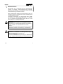
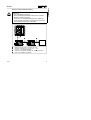
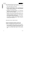
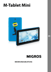
392 987 Kurzübersicht Quick reference Hinweise zur Installation und Inbetriebnahme des SPC200 Notes on installing and commissioning the SPC200 9904a SPC200-... Deutsch 3 English 13 (Festo AG & Co., D-73726 Esslingen, 1999) 9904a 2 1 Benutzerhinweise Der SPC200 dient, in Verbindung mit den zugehörigen Baugruppen und Modulen, bestimmungsgemäß als Positioniersteuerung und Lageregler für Pneumatische Achsen sowie als Positioniersteuerung für elektrische Achsen. Diese Kurzübersicht enthält eine Zusammenfassung der notwendigen Schritte zur Inbetriebnahme eines Positioniersystems mit Pneumatischen Achsen. Ausführliche Informationen zum SPC200 finden Sie im Bediener-Handbuch zum SPC200 (Typ P.BE-SPC200-...). Informationen zu speziellen Erweiterungsbaugruppen finden Sie in den Beschreibungen zur jeweiligen Baugruppe. VORSICHT: Diese Kurzübersicht richtet sich an ausgebildete Fachleute der Steuerungs- und Automatisierungstechnik, die Erfahrung mit der Installation und Inbetriebnahme des SPC200 besitzen. Beachten Sie unbedingt die sicherheitstechnischen Hinweise im Bediener-Handbuch zum SPC200, Typ P.BE-SPC200-.... WARNUNG: Schalten Sie vor Installations- und Wartungsarbeiten folgendes in der angegebenen Reihenfolge aus: 1. Druckluftversorgung 2. Last- und Betriebsspannungsversorgung am SPC200 und ggf. Lastspannungsversorgung am Achsinterface-Strang. 9904a 3 Deutsch SPC200-... SPC200-... Deutsch 2 Installationshinweise Pneumatische Achse Systemübersicht 1 2 3 7 6 1 2 3 4 5 6 7 4 4 5 Meßsystem Achsinterface für die erste Achse; Typ SPC-AIF-... Smart Positioning Controller SPC200; Typ SPC200-... Achsinterface für die zweite Achse (Optional), Typ SPC-AIF-... Optional: zusätzliche Module mit insgesamt max. 16 Ein-/Ausgängen (z.B. SPC200-FIO-2E/2A-M8) Proportional-Wegeventil Typ MPYE-... Zylinder 9904a SPC200-... Deutsch Hinweise zum Achsinterface-Strang VORSICHT: • Nur Originalkabel verwenden. • Maximal zulässige Kabellänge zwischen den einzelnen Modulen unbedingt beachten. • Prüfen Sie, ob ein Abschlußwiderstand Typ KABS-M9R100 und/oder eine externe Lasteinspeisung erforderlich sind (siehe Beschreibung zum SPC200). 1 1 2 3 4 9904a 2 3 4 Kabel für die erste Achse, Typ KSPC-AIF-1-WD Kabel für die zweite Achse, Typ KVI-CP-1-... oder KVI-CP-2-... (schleppkettentauglich) Kabel für weitere Module, Kabeltyp wie unter beschrieben Buchse für Ventilkabel Typ KMPYE-... 2 5 SPC200-... Deutsch Beschaltungsbeispiel für die Betriebsart Start/Stop mit Steuerung über eine E/A-Baugruppe 24 V STOP (7) START (8) ENABLE (9) 6 24 V 0V 24 L READY (7) Voraussetzungen – – – – Startprogramm im Programmspeicher Achs-, Applikationsdaten und Hardware eingestellt Betriebsart Start/Stop eingestellt 1-Signal an ENABLE und STOP Bedienung mit Bedienfeld – Start, Stop, Reset über Menü SYSTEM CONTROL am Bedienfeld Bedienung über E/A – Start durch steigende Flanke an START – Stop durch 0-Signal an STOP – Programm fortsetzen durch 1-Signal an STOP und steigende Flanke an START – Reset durch 0-Signal an STOP und steigende Flanke am START-Eingang – Regler abschalten durch 0-Signal an ENABLE 9904a 3 Inbetriebnahme Pneumatischer Achsen mit WinPISA Um die Inbetriebnahme von Achsen durchführen zu können, muß zunächst die gewünschte Hardware-Konfiguration am SPC200 hergestellt werden. Schritt 1: Nachbilden der vorhandenen Hardwarekonfiguration in einem WinPISA-Projekt Hardwarekonfiguration des SPC200 auslesen (Empfehlung): 1. Online Modus aktivieren (Befehl [Online] [Online Modus]). Wenn Ihre Hardware-Konfiguration von der gespeicherten Sollkonfiguration abweicht, erhalten Sie eine Fehlermeldung (00004001). Prüfen Sie, ob die Status-LEDs aller angeschlossenen Module leuchten und die Module somit erkannt wurden. Quittieren Sie in diesem Fall die Fehlermeldung mit "Ja". Sofern sich die Achszuordnung geändert hat, erscheint in einer weiteren Meldung, daß hierzu ein Datenreset notwendig ist. Sofern keine Daten im SPC200 vorhanden sind, die vorher in einem WinPISA-Projekt gesichert werden sollten, können Sie mit "Weiter" den Daten-Reset ausführen. Nach dem Daten-Reset bzw. beim Laden des Projekts (siehe Schritt 2) wird die eingestellte Konfiguration als Sollkonfiguration gespeichert. Ab Werk ist der SPC200 vorbereitet, die aktuelle HardwareKonfiguration in der ersten Einschaltphase selbsttätig als Sollkonfiguration zu speichern (es erfolgt keine Fehlermeldung). 2. Projekt auslesen (Befehl [Online] [Upload] [Projekt]). Projektnamen eingeben und bestätigen. Titel eingeben und bestätigen. 9904a 7 Deutsch SPC200-... SPC200-... Deutsch Oder Hardwarekonfiguration manuell einstellen: 1. Projekt anlegen (Befehl [Datei] [Projekt neu]) bzw. Projekt öffnen (Befehl [Datei] [Projekt öffnen]). 2. SPC200 ins Projekt einfügen. Hierzu im Projektfenster das Symbol "Hardware" auswählen und im Menü [Bearbeiten] den Befehl [Objekt einfügen] wählen. Den Eintrag "SPC200" auswählen und Auswahl bestätigen. 3. Konfiguration des SPC200 einstellen. (Im Dialogfenster "SPC200 Konfiguration" Basisgerät und Baugruppen korrekt einstellen und Auswahl bestätigen). 4. Hardware (Achse oder E/A-Modul) einfügen. Hierzu im Projektfenster das Symbol des Achsinterface-Strangs bzw. der Schrittmotor-Anschaltung auswählen und im Menü [Bearbeiten] den Befehl [Objekt einfügen] wählen. Den gewünschten Eintrag "Positionierachse" oder "E/A-Modul" auswählen. Anschließend die verwendete Achse bzw. das gewünschte E/A-Modul auswählen. Diesen Vorgang für alle Komponenten wiederholen. Pneumatische Achse in Betrieb nehmen: Schritt 2: Achsspezifische Parameter einstellen und Projekt in den SPC200 laden (Pneumatische Achse) 1. Achs- und Applikationsdaten einstellen. Hierzu im Projektfenster das Symbol der gewünschten Achse markieren und im Menü [Bearbeiten] den Befehl [Konfigurieren] wählen. Nun die Achs- und Applikationsdaten korrekt einstellen. Erläuterungen zu den einzelnen Daten finden Sie in der WinPISAHilfe. 8 9904a 2. Ggf. Achs- und Applikationsdaten für weitere Achsen einstellen wie unter 1. beschrieben. HINWEIS: Die Reglerdaten werden i.d.R. nicht verändert. 3. Ggf. Online Modus aktivieren (Befehl [Online], [Online Modus]). Wenn Ihre Hardware-Konfiguration von der gespeicherten Sollkonfiguration abweicht, erhalten Sie eine Fehlermeldung (00004001). Entspricht die eingestellte Konfiguration der tatsächlichen Konfiguration, wird diese durch Laden des Projekts zur Sollkonfiguration. 4. Projekt laden (Befehl [Online] [Download] [Projekt]. Schritt 3: Verschlauchung prüfen (Optional) Hierzu können Sie den Bewegungstest durchführen (siehe WinPISA- bzw. SPC200-Handbuch). Schritt 4: Statische und ggf. dynamische Identifikationsfahrt durchführen Vor der Identifikation: 1. Betriebsdruck korrekt einstellen (Standardeinstellung = 6 bar). 2. An den Eingängen ENABLE und STOP 1-Signal anlegen. Bei der Erstinbetriebnahme ist zur Reglerfreigabe eine steigende Flanke am Eingang ENABLE erforderlich. 3. Ggf. Online Modus aktivieren (Befehl [Online] [Online Modus]). 9904a 9 Deutsch SPC200-... SPC200-... Deutsch Identifikation durchführen: 1. Befehl [Online] [Inbetriebnahme] [Identifikation] auswählen. 2. Im Dialogfenster "Identifikation" die gewünschte Achse sowie die gewünschte Identifikationsart (dynamisch/statisch) auswählen. WARNUNG: Bei der Identifikation wird eine Achse mit höchster Beschleunigung und Geschwindigkeit in Bewegung gesetzt. Stellen Sie sicher, daß: - der gesamte Verfahrbereich der Achse frei ist, - die korrekten Achs- und Applikationsdaten eingestellt sind. 3. Identifikation mit Schaltfläche "Start" starten. HINWEIS: Die Identifikation nimmt eine gewisse Zeit in Anspruch. Schritt 5: Meßsystem kalibrieren (Optional) Bei Bedarf Meßsystem kalibrieren (siehe WinPISA- bzw. SPC200-Handbuch). Schritt 6: Achse manuell verfahren (Optional) Funktionsfähigkeit des Reglers und Wirksamkeit der Softwareendlagen prüfen (siehe WinPISA- bzw. SPC200-Handbuch). 10 9904a SPC200-... 1. Programm anlegen und öffnen. Hierzu das Softwaresymbol markieren und im Menü [Bearbeiten] den Befehl [Objekt einfügen] wählen. Im Dialogfenster "Neues Programm" Programmnummer (0), Titel und ggf. Beschreibung zum Programm eingeben und Eingabe bestätigen. Oder bestehendes Programm öffnen. 2. Im Programmfenster das Programm eingeben, z.B.: N000 G01 X50 FX50 ;Pos. 50 ggf. anpassen! N001 G01 X200 FX50 ;Pos. 200 ggf. anpassen! N002 M30 ;Programmende 3. Bei Bedarf Syntaxprüfung durchführen (Befehl [Übersetzen] [Syntaxprüfung]). 4. Programm in den SPC200 laden (Befehl [Online] [Download] [Programme], Programm auswählen, bestätigen mit "Ok"). Schritt 8: Betriebsart und Startprogramme einstellen 1. Ggf. Online Modus aktivieren (Befehl [Online] [Online Modus]). 2. Im Projektfenster das Symbol "SPC200-.." markieren und das Dialogfenster "SPC200 Konfiguration" öffnen (Befehl [Bearbeiten] [Konfigurieren]. 3. In der Registerkarte "Betriebsart/Startprogramme" die Betriebsart und die Startprogramme einstellen. 9904a 11 Deutsch Schritt 7: Testprogramm eingeben SPC200-... Deutsch Empfehlung (zur Erstinbetriebnahme): Eingegebenes Testprogramm als Startprogramm A festlegen. Startprogramm B deaktivieren (Startpr. B=***). Die Betriebsart Start/Stop einstellen. Programme lassen sich dann unabhängig von einer übergeordneten SPS/IPC z.B. mit dem Bedienfeld steuern (leichtere Testmöglichkeiten). 4. Einstellungen mit "Download" in den SPC200 laden. 5. Übernehmen der Einstellungen mit "Ok". Änderungen im Projekt speichern (bei aktivem Projektfenster Befehl [Datei] [Speichern]). Schritt 9: Programm im Debug Modus oder im Dauerlauf testen Voraussetzungen: – Programm im Programmspeicher – Achs- und Applikationsdaten eingestellt und Projekt in den SPC200 geladen. – Betriebsart Start/Stop und Startprogramm eingestellt. – An ENABLE und STOP liegt 1-Signal an. Programm im Debug Modus testen • Programm testen mit Hilfe des Debug Modus in WinPISA (Befehl [Online] [Achsen steuern] oder mit dem Bedienfeld (Menü TEST/DIAG, Befehl SINGLE STEP). Programm starten • 12 Programm starten durch steigende Flanke am START-Eingang oder mit dem Bedienfeld (Menü SYSTEM CONTROL, Befehl START SYSTEM). 9904a SPC200-... 1 User instructions This quick reference contains a summary of the steps required for commissioning a positioning system with pneumatic axes. More detailed information on the SPC200 can be found in the user manual for the SPC200 (type P.BE-SPC200-...). Information on special extension modules can be found in the manuals for the relevant module. CAUTION This quick reference is directed at engineers who are trained in control and automation technology and who are experienced in installing and commissioning the SPC200. Please observe strictly the safety instructions in the SPC200 user manual, type P.BE-SPC200-... WARNING Switch off the following in the order specified before carrying out installation and maintenance work: 1. the compressed air supply 2. the load and operating voltage supply to the SPC200 and, if necessary, the load voltage supply to the axis interface string. 9904a 13 English The SPC200 is designed for use in conjunction with the accessory modules (in the rack and as field devices) as positioning controller and closed loop controller for pneumatic axes as well as positioning controller for electric axes. SPC200-... 2 Installing the pneumatic axis System overview English 1 2 3 7 6 1 2 3 4 5 6 7 14 4 5 Measuring system Axis interface for the first axis; type SPC-AIF-... Smart Positioning Controller SPC200; type SPC200-... Axis interface for the second axis (optional), type SPC-AIF-... Optional: additional modules with max. 16 inputs/outputs altogether (e.g. SPC200-FIO-2E/2A-M8) Proportional directional valve type MPYE-... Cylinder 9904a SPC200-... CAUTION • Use only original cables. • Observe the maximum permitted cable lengths between the individual modules on the axis interface. • Check if a terminating resistor type KABS-M9-R100 and/or an external load voltage supply is necessary (see SPC200 manual). 1 1 2 3 4 9904a 2 3 4 Cable for the first axis, type KSPC-AIF-1-WD Cable for the second axis, type KVI-CP-1-... or KVI-CP-2-... (can be used with drag chains) Cable for further modules, type of cables as under Valve connection for cable type KMPYE-... 2 15 English Notes on axis interface string SPC200-... Example of connection diagram for start/stop operating mode controlled via an I/O module 24 V English STOP (7) START (8) ENABLE (9) 16 24 V 0V 24 L READY (7) Requirements – – – – Start program in program memory Axes data, application data and hardware set Start/stop operating mode set 1-signal at ENABLE and STOP Operation with operating panel – Start, stop, reset via menu SYSTEM CONTROL at the operating panel Operation via I/Os – Start with positive edge at START input – Stop with 0-signal at STOP – Start/continue programs with 1-signal at STOP and rising edge at START input – Reset with 0-signal at STOP and positive edge at START – Switch off controller with 0-signal at ENABLE 9904a SPC200-... 3 Commissioning pneumatic axes with WinPISA In order to commission axes, the desired hardware configuration must first be set on the SPC200. English Step 1: Simulate the existing hardware configuration in a WinPISA project Read out hardware configuration of the SPC200 (recommendation): 1. Activate online mode (command [Online] [Online mode]). If your hardware configuration differs from the saved reference configuration, you will receive an error message (00004001). Check that the status LEDs of all the connected modules light up and that the modules are thereby recognised. In this case, acknowledge the error message with "Yes." If the axis assignment has been modified, a further message will inform you that a data reset is required. If there are no data in the SPC200 which should be saved in a WinPISA project, you can carry out a data reset with "Continue." After the data reset, or when the project is loaded (see step 2), the set configuration will be saved as the reference configuration. When leaving the factory, the SPC200 is prepared for saving the current hardware configuration in the first start-up phase automatically as the reference configuration (there is no error message). 2. Read out project (command [Online] [Upload] [Project]). Enter the project name and confirm. Enter the title and confirm. 9904a 17 SPC200-... Or set hardware configuration manually: 1. Create project (command [File] [New project]) or open project (command [File] [Open project]). English 2. Insert the SPC200 into the project. To do this, select the icon "Hardware" in the project window and the command [Insert object] in the menu [Edit]. Then select the entry "SPC200" and confirm. 3. Set the configuration of the SPC200. (Set the basic unit and modules correctly in the dialogue window "SPC200 configuration" and confirm the selection). 4. Insert hardware (axis or I/O module). To do this, select the icon for the axis interface string or for the stepping motor interface in the project window and select the command [Insert object] in the menu [Edit]. Then select the desired entry "Positioning axis" or "I/O module." Then select the axis used or the desired I/O module. Repeat this procedure for all the components. Commissioning a pneumatic axis Step 2: Set the axis-specific parameters and load the project into the SPC200 (pneumatic axis) 1. Set the axis and appplication parameters. To do this, mark the icon for the desired axis in the project window and select the command [Configure] in the menu [Edit]. Now set the axis and application parameters correctly. You will find explanations on the individual parameters in the WinPISA help. 18 9904a SPC200-... 2. If necessary, set the axis and application parameters for further axes as described under 1. 3. If necessary, activate online mode (command [Online], [Online mode]). If your hardware configuration differs from the saved reference configuration, you will receive an error message (00004001). If the set configuration corresponds to the actual configuration, this will become the reference configuration when the project is loaded. 4. Load the project (command [Online] [Download] [Project]. Step 3: Check tubing (optional) To do this you can carry out the movement test (see WinPISA or SPC200 manual). Step 4: Carry out the static and, if necessary, the dynamic identification travel Before identification: 1. Set the correct operating pressure (standard setting = 6 bar). 2. Apply a 1-signal to the inputs ENABLE and STOP. During the first commissioning, a rising edge is required at the ENABLE input to enable the controller. 3. If necessary, activate online mode (command [Online] [Online mode]). 9904a 19 English PLEASE NOTE Controller parameters are not usually modified. SPC200-... Carry out the identification: 1. Select the command [Online] [Commissioning] [Identification]. English 2. Select the desired axis and the desired type of identification (dynamic/static) in the dialogue window "Identification." WARNING During identification, an axis is set in motion with the highest acceleration and at the highest speed. Make sure that: – the complete positioning range of the axis is free – the correct axis and application parameters are set. 3. Start the identification with the button "Start." PLEASE NOTE The identification requires a certain amount of time. Step 5: Calibrate the measuring system (optional) If necessary, calibrate the measuring system (see WinPISA or SPC200 manual). Step 6: Move the axis manually (optional) Check the functionability of the controller and the effectiveness of the software end positions (see WinPISA or SPC200 manual). 20 9904a SPC200-... 1. Create the program and open it. To do this, mark the software icon and select the command [Insert object] in the menu [Edit]. Enter the program number (0), the title and, if applicable, a description of the program in the dialogue window "New program" and confirm the entry. Or open the existing program. 2. Enter the program in the N000 G01 X50 FX50 N001 G01 X200 FX50 N002 M30 program window, e.g.: ;Adapt pos. 50 ;Adapt pos. 200 ;Program end 3. Carry out a syntax check if required (command [Compile] [Syntax check]). 4. Load the program into the SPC200 (command [Online] [Download] [Programs], select program, confirm with "OK"). Step 8: Set operating mode and start programs 1. If necessary, activate the online mode (command [Online] [Online mode]). 2. Mark the icon "SPC200-.." in the project window and open the dialogue window "SPC200 configuration" (command [Edit] [Configure]. 3. Set the operating mode and the start programs in the tab card "Operating mode/Start programs." 9904a 21 English Step 7: Enter a test program SPC200-... Recommendation (for first commissioning): Determine the test program entered as start program A. Deactivate start program B (Startpr. B=***). Set the operating mode Start/Stop. Programs can then be controlled independently of a higher-order PLC/IPC e.g. with the control panel (easier test possibilities). English 4. Load the settings into the SPC200 with "Download." 5. Accept the settings with "OK". Save any modifications to the project (with active project window, command [File] [Save]). Step 9: Test the program in Debug mode or in continuous run Requirements: – the program must be in program memory – the axis and application parameters must be set and the project loaded into the SPC200 – the operating mode Start/Stop and the start program must be set – There must be a 1-signal at ENABLE and STOP. Test the program in Debug mode • Test the program with the Debug mode in WinPISA (command [Online] [Control axes] or with the control panel (command SINGLE STEP, TEST/DIAG). Start the program • 22 Start the program with a rising edge at the START input or with the control panel (command START SYSTEM, menu SYSTEM CONTROL). 9904a