1
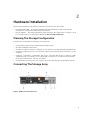
Dell PowerVault MD3400 and MD3420 Series
Storage Arrays
Deployment Guide
Notes, Cautions, and Warnings
NOTE: A NOTE indicates important information that helps you make better use of your computer.
CAUTION: A CAUTION indicates either potential damage to hardware or loss of data and tells you
how to avoid the problem.
WARNING: A WARNING indicates a potential for property damage, personal injury, or death.
Copyright © 2014 Dell Inc. All rights reserved. This product is protected by U.S. and international copyright and
intellectual property laws. Dell™ and the Dell logo are trademarks of Dell Inc. in the United States and/or other
jurisdictions. All other marks and names mentioned herein may be trademarks of their respective companies.
2014 - 02
Rev. A00
Contents
1 Introduction................................................................................................................5
System Requirements............................................................................................................................5
Management Station Requirements............................................................................................... 5
Introduction to Storage Arrays..............................................................................................................5
Related Documentation........................................................................................................................6
Locating Your System Service Tag....................................................................................................... 6
Contacting Dell......................................................................................................................................7
Documentation Feedback.....................................................................................................................7
2 Hardware Installation.............................................................................................. 9
Planning The Storage Configuration ................................................................................................... 9
Connecting The Storage Array ............................................................................................................ 9
Cabling The Storage Array.................................................................................................................. 10
Redundant And Nonredundant Configurations........................................................................... 10
Single Controller Configurations...................................................................................................11
Dual Controller Configurations.....................................................................................................14
Cabling PowerVault MD1200 Series Expansion Enclosures..............................................................20
Expanding With Previously Configured PowerVault MD1200 Series Expansion Enclosures......21
Expanding With New PowerVault MD1200 Series Expansion Enclosures.................................. 22
3 Installing PowerVault MD Storage Software................................................... 23
Graphical Installation (Recommended)............................................................................................. 24
Console Installation............................................................................................................................ 24
Silent Installation................................................................................................................................. 25
Silent Installation On Windows Systems...................................................................................... 25
Silent Installation On Linux Systems............................................................................................. 25
Upgrading MD Storage Software........................................................................................................25
4 Uninstalling MD Storage Software..................................................................... 27
Uninstalling MD Storage Software From Windows............................................................................27
Uninstalling MD Storage Software From Windows Server GUI Versions.................................... 27
Uninstalling MD Storage Software From Windows Server Core Versions.................................. 27
Uninstalling MD Storage Software From Linux.................................................................................. 27
5 Load Balancing........................................................................................................29
Load Balance Policy............................................................................................................................ 29
Round Robin With Subset............................................................................................................. 29
Least Queue Depth....................................................................................................................... 29
Least Path Weight..........................................................................................................................29
Changing Load Balance Policies On The Windows Server Operating System...........................30
Introduction
1
This document provides information about deploying Dell PowerVault MD3400 and Dell PowerVault
MD3420 storage arrays. The deployment process includes:
•
•
•
Hardware installation
Modular Disk Storage Manager (MDSM) software installation
Initial system configuration
Other information includes system requirements, storage array organization, and utilities.
NOTE: For more information on product documentation, see Related Documentation.
MDSM enables an administrator to configure and monitor storage arrays for optimum usability. The
version of MDSM included on the PowerVault MD series resource media can be used to manage both the
Dell PowerVault MD3400 and Dell PowerVault MD3420 systems and the earlier PowerVault MD series
storage arrays. MDSM is compatible with both Microsoft Windows and Linux operating systems.
System Requirements
Before installing and configuring the PowerVault MD3400 and MD3420 series hardware and software,
ensure that the minimum system requirements are met, and the supported operating system is installed.
For more information, see the Dell PowerVault MD34xx/38xx Series Support Matrix at dell.com/support/
manuals.
Management Station Requirements
A management station uses MDSM to configure and manage storage arrays across the network. For
management station requirements, see Dell PowerVault MD34xx/38xx Series Support Matrix at dell.com/
support/manuals.
Introduction to Storage Arrays
A storage array includes various hardware components, such as physical disks, RAID controller modules,
fans, and power supplies, gathered into enclosures. The physical disks are accessed through the RAID
controller modules.
One or more host servers attached to the storage array can access the data on the storage array. You can
also establish multiple physical paths between the hosts and the storage array so that loss of any single
path (for example, through failure of a host server port) does not result in loss of access to data on the
storage array.
The storage array is managed by MDSM running on a:
•
•
Host server — On a host server system, MDSM and the storage array communicate management
requests and event information using in-band or out-of band-connections.
Management station — On a management station, MDSM communicates with the storage array either
through an Ethernet connection to the storage array management port or through an Ethernet
5
connection to a host server. The Ethernet connection passes management information between the
management station and the storage array connectivity.
Using MDSM, you can configure the physical disks in the storage array into logical components called
disk groups or dynamic disk group and then divide the disk groups into virtual disks. Disk groups are
created in the unconfigured capacity of a storage array. Virtual disks are created in the free capacity of a
disk group.
Unconfigured capacity comprises physical disks not already assigned to a disk group. When a virtual disk
is created using unconfigured capacity, a disk group or dynamic disk group is automatically created. If the
only virtual disk in a disk group is deleted, the disk group is also deleted. Free capacity is space in a disk
group that is not assigned to any virtual disk.
Data is written to the physical disks in the storage array using RAID technology. RAID levels define how
data is written to physical disks. Different RAID levels offer different levels of accessibility, redundancy,
and capacity. You can set a specified RAID level for each disk group and virtual disk on your storage array.
For more information about using RAID and managing data in your storage solution, see the Owner’s
Manual at dell.com/support/manuals.
Related Documentation
NOTE: For all PowerVault documentation, go to dell.com/powervaultmanuals and enter the
system Service Tag to get your system documentation.
NOTE: For all Dell OpenManage documents, go to dell.com/openmanagemanuals.
NOTE: For all storage controller documents, go to dell.com/storagecontrollermanuals.
Your product documentation includes:
•
Dell PowerVault MD3400/3420/3800i/3820i/3800f/3820f Storage Arrays Getting Started Guide —
Provides an overview of system features, setting up your system, and technical specifications. This
document is also shipped with your system.
•
Dell PowerVault MD3400 and 3420 Storage Arrays Owner’s Manual — Provides information about
system features and describes how to troubleshoot the system and install or replace system
components.
•
Rack Installation Instructions — Describes how to install your system into a rack. This document is
also shipped with your rack solution.
•
Dell PowerVault MD Series Storage Arrays Administrator's Guide — Provides information about
configuring and managing the system using the MDSM GUI.
•
Dell PowerVault Modular Disk Storage Arrays CLI Guide — Provides information about configuring and
managing the system using the MDSM CLI.
•
Dell PowerVault MD3400 and 3420 Storage Arrays Deployment Guide — Provides information about
deploying the storage system in the SAN architecture.
•
Dell PowerVault MD34xx/38xx Series Support Matrix — Provides information about the software and
hardware compatibility matrices for the storage array.
Locating Your System Service Tag
Your system is identified by a unique Express Service Code and Service Tag number. The Express Service
Code and Service Tag are found on the front of the system by pulling out the information tag.
Alternatively, the information may be on a sticker on the chassis of the system. This information is used
by Dell to route support calls to the appropriate personnel.
6
Contacting Dell
NOTE: If you do not have an active Internet connection, you can find contact information on your
purchase invoice, packing slip, bill, or Dell product catalog.
Dell provides several online and telephone-based support and service options. Availability varies by
country and product, and some services may not be available in your area. To contact Dell for sales,
technical support, or customer service issues:
1.
Go to dell.com/contactdell.
2.
Verify your country or region from the drop-down menu at the top left corner of the page.
3.
Select your support category: Technical Support, Customer Support, Sales, or International
Support Services.
4.
Select the appropriate service or support link based on your requirement.
NOTE: If you have purchased a Dell system, you may be asked for the Service Tag.
Documentation Feedback
If you have feedback for this document, write to [email protected]. Alternatively, you
can click on the Feedback link in any of the Dell documentation pages, fill out the form, and click Submit
to send your feedback.
7
8
Hardware Installation
2
Before using this guide, ensure that you review the instructions in the documents:
•
Getting Started Guide — The Getting Started Guide shipped with the storage array provides
information to configure the initial setup of the system.
•
Owner’s Manual — The Owner’s Manual provides information about important concepts to set up
your storage solution. See the Owner’s Manual at dell.com/support/manuals.
Planning The Storage Configuration
Consider the following before installing your storage array:
•
Evaluate data storage needs and administrative requirements.
•
Calculate availability requirements.
•
Decide the frequency and level of backups, such as weekly full backups with daily partial backups.
•
Consider storage array options, such as password protection and email alert notifications for error
conditions.
•
Design the configuration of virtual disks, disk groups, or dynamic disk groups according to a data
organization plan. For example, use one virtual disk for inventory, a second for financial and tax
information, and a third for customer information.
•
Decide whether to allow space for hot spares, which automatically replace failed physical disks.
Connecting The Storage Array
Figure 1. RAID Controller Module Ports
9
Item
Number
Name
Description
1
12 gbps SAS Host Ports (2)
Allows you to connect host servers to the
storage array.
2
7–segment display
Displays status of the controller.
3
1G Ethernet Management (MGMT) Port (1)
Allows for out of band management of
storage array.
4
Reserved Ethernet Port (1)
This is a reserved port.
5
12 gbps SAS Host Ports (2)
Allows you to connect host servers to the
storage array.
6
SAS Expansion Ports (2)
Allows you to connect the storage array to
optional PowerVault MD1200 series
expansion enclosures for additional storage
capacity.
NOTE: Only one SAS OUT expansion port can be used at a time and the recommended expansion
port is port 0.
NOTE: Do not cable the reserved management port.
Each PowerVault MD3400 and MD3420 storage array can be expanded to a maximum of 120 slots (or
192, if enabled using Premium Feature activation) through a maximum of seven MD1200 series expansion
enclosures.
Cabling The Storage Array
You can cable the storage array to host servers with:
•
Single path data configuration — A single path configuration allows you to connect a maximum of
eight hosts. This is a non-redundant configuration.
•
Dual path data configuration — A dual path configuration allows you to connect a maximum of four
hosts.
Choose the data configuration based on:
•
Number of hosts required
•
Level of data redundancy required
Redundant And Nonredundant Configurations
Nonredundant configurations are configurations that provide only a single data path from a host to the
storage array. This type of configuration is only recommended for noncritical data storage. Path failure
from a failed or removed cable, or a failed or removed RAID controller module results in loss of host
access to storage on the storage array.
Redundancy is established by installing separate data paths between the host and the storage array. Each
data path is connected to one of the two RAID controller modules installed in the storage array.
Redundancy protects the host from losing access to data in the event of path failure, because both RAID
controller modules can access all the disks in the storage array.
10
Single Controller Configurations
The following figures show two and four hosts, each connected to only one RAID controller module. The
hosts can share storage space but without redundant paths, if one path fails, the server on that path
would be disconnected from the storage array.
Figure 2. One Host Connected to a Single Controller
11
Figure 3. Two Hosts Connected to a Single Controller Using Two HBAs
12
Figure 4. Two Hosts Connected to a Single Controller Using One HBA
13
Figure 5. Four Hosts Connected to a Single Controller
Dual Controller Configurations
The following figures show two and four hosts, each connected to two RAID controller modules. Since
each host has redundant paths, loss of a single path still allows access to the storage array through the
alternate path.
14
Figure 6. Two Hosts Connected to Two Controllers
15
Figure 7. Four Hosts Connected to Two Controllers Using Two HBAs
16
Figure 8. Four Hosts Connected to Two Controllers Using One HBA
The following figure shows eight hosts, each connected to only one RAID controller module. This
configuration allows the maximum number of hosts that can be connected, but provides no redundancy.
17
Figure 9. Eight Hosts Connected to Two Controllers
The following figures show up to four cluster nodes connected to two RAID controller modules. Since
each cluster node has redundant paths, loss of a single path would still allow access to the storage array
through the alternate path.
18
Figure 10. Four Cluster Nodes Connected to Two Controllers
19
Figure 11. Four Cluster Nodes Connected to Two Controllers
Cabling PowerVault MD1200 Series Expansion Enclosures
You can expand the capacity of your PowerVault MD3400 and MD3420 storage array by adding
PowerVault MD1200 series expansion enclosures. You can expand the physical disk pool to a maximum
of 120 slots (or 192, if enabled using Premium Feature activation) using a maximum of seven expansion
enclosures.
To connect an MD1200 series expansion enclosure to your MD3400 series array:
1.
Connect the supported SAS cable (MiniSAS HD end) to the SAS OUT Port 0 on the MD3400 series
storage array.
2.
Connect the other end of the SAS cable to the IN port on one of the MD1200 series Enclosure
Management Modules (EMM).
3.
To add more MD1200 expansion enclosures, daisy chain them to the first expansion enclosure.
20
Expanding With Previously Configured PowerVault MD1200 Series Expansion
Enclosures
CAUTION: If a PowerVault MD1200 series expansion enclosure that was previously attached to a
PERC H800 adapter is used as an expansion enclosure to a PowerVault MD series storage array,
the physical disks of the expansion enclosure are reinitialized and data is lost. You must back up
all data on the expansion enclosure before attempting the expansion.
Use this procedure if your expansion enclosure is directly attached to and configured on a Dell
PowerEdge RAID Controller (PERC) H800 adapter. Data from virtual disks created on a PERC H800
adapter cannot be directly migrated to a PowerVault MD series storage array or to a PowerVault MD1200
series expansion enclosure connected to a PowerVault MD series storage array.
To attach previously configured PowerVault MD1200 series expansion enclosures to the PowerVault
MD3400 or PowerVault MD3420 storage array:
1.
Back up all data on the expansion enclosures.
2.
Upgrade the expansion enclosure firmware to the latest version available at dell.com/support while
the enclosure is still attached to the PERC H800 controller.
Windows systems users can reference the DUP.exe package and Linux kernel users can reference
the DUP.bin package.
3.
Ensure that the storage array software is installed and up to date before adding the expansion
enclosures. For more information, see the Dell PowerVault MD34xx/38xx Series Support Matrix at
dell.com/support/manuals.
a) Install the software and driver package from the PowerVault MD series resource media. For
information about installing the software, see Installing PowerVault MD Storage Software.
b) Update the storage array RAID controller module firmware and NVSRAM to the latest versions
available at dell.com/support.
c) Using MDSM, click Tools → Upgrade RAID Controller Module Firmware → Enterprise
Management Window (EMW).
4.
Stop all I/O and turn off the system and attached units.
a) Turn off the storage array.
b) Turn off the expansion enclosures.
5.
Cable the expansion enclosures to the storage array.
a) Connect the MiniSAS HD end of the supported SAS cabled to the SAS OUT Port 0 on the MD
1200 series array.
b) Connect the other end of the SAS cable to the IN port on the MD 1200 series array.
6.
Turn on the attached units:
a) Turn on the expansion enclosures. Wait for the enclosure status LEDs to light blue.
b) Turn on the storage array and wait for the status LEDs to indicate that the unit is ready:
*
If the status LEDs are solid amber, the storage array is still coming online.
*
If the status LEDs are blinking amber, there is an error that can be viewed using the MDSM.
* If the status LEDs are solid blue, the storage array is ready.
c) After the storage array is online and ready, turn on any attached host systems.
7.
After the PowerVault MD1200 series expansion enclosure is configured as an expansion enclosure of
the storage array, restore the data that was backed up in step 1.
After the expansion enclosures are online, they can be accessed as a part of the storage array.
21
Expanding With New PowerVault MD1200 Series Expansion Enclosures
Perform the following steps to attach new PowerVault MD1200 series expansion enclosures to a
PowerVault MD3400 or PowerVault MD3420 storage array:
1.
Before adding the expansion enclosure(s), ensure that the storage array software is installed and is up
to date. For more information, see the Dell PowerVault MD34xx/38xx Series Support Matrix at
dell.com/support/manuals.
a) Install the software and driver package included on the PowerVault MD series resource media. For
information about installing the software, see Installing PowerVault MD Storage Software.
b) Set up the PowerVault MD1200 series expansion enclosure(s). For information about setting up
the PowerVault MD1200 series expansion enclosure(s), see the Owner’s Manual at dell.com/
support/manuals.
c) Using MDSM, update the RAID controller module firmware and NVSRAM to the latest versions
available on dell.com/support/manuals.
d) Click Tools → Upgrade RAID Controller Module Firmware from the Enterprise Management
Window (EMW).
2.
Stop I/O and turn off all systems:
a) Stop all I/O to the storage array and turn off affected host systems attached to the storage array.
b) Turn off the storage array.
c) Turn off any expansion enclosure(s) in the affected system.
3.
Cable the expansion enclosure(s) to the storage array.
a) Connect the MiniSAS HD end of the supported SAS cabled to the SAS OUT Port 0 on the MD
1200 series array.
b) Connect the other end of the SAS cable to the IN port on the MD 1200 series array.
4.
Turn on attached units:
a) Turn on the expansion enclosure(s). Wait for the enclosure status LED to light blue.
b) Turn on the storage array and wait for the status LED to indicate that the unit is ready:
*
If the status LEDs are solid amber, the storage array is still coming online.
*
If the status LEDs are blinking amber, there is an error that can be viewed using MDSM.
* If the status LEDs are solid blue, the storage array is ready.
c) After the storage array is online and ready, turn on any attached host systems.
5.
Using MDSM, update all attached expansion enclosure firmware if it is out of date:
a) From the EMW, select the enclosure that you want to update and enter the Array Management
Window (AMW).
b) Click Advanced → Maintenance → Download → EMM Firmware.
c) Select Select All to update all the attached expansion enclosures simultaneously.
22
Installing PowerVault MD Storage
Software
3
The Dell PowerVault MD series resource media contains software and drivers for both Linux and
Microsoft Windows operating systems.
The root of the media contains a readme.txt file covering changes to the software, updates, fixes,
patches, and other important data applicable to both Linux and Windows operating systems. The
readme.txt file also specifies requirements for accessing documentation, information regarding versions
of the software on the media, and system requirements for running the software.
For more information on supported hardware and software for Dell PowerVault systems, see the Dell
PowerVault MD34xx/38xx Series Support Matrix at dell.com/support/manuals.
NOTE: It is recommended that you install all the latest updates available at dell.com/support/
manuals.
The PowerVault MD series resource media provides features that include the core software, providers,
and optional utilities. The core software feature includes the host-based storage agent, multipath driver,
and Modular Disk Storage Manager (MDSM) application used to configure, manage, and monitor the
storage array solution. The providers feature includes providers for the Microsoft Virtual Disk Service
(VDS) and Microsoft Volume Shadow-Copy Service (VSS) framework.
NOTE: For more information about the Microsoft VDS and Microsoft VSS providers, see the Owner's
Manual. To install the software on a Windows or Linux system, you must have administrative or root
privileges.
NOTE: If Dynamic Host Configuration Protocol (DHCP) is not used, initial configuration of the
management station must be performed on the same physical subnet as the storage array.
Additionally, during initial configuration, at least one network adapter must be configured on the
same IP subnet as the storage array’s default management port (Controller 0 MGMT (port 1):
192.168.129.101 or Controller 1 MGMT (port 1): 192.168.129.102). After initial configuration,
the management ports are configured using MDSM and the management station’s IP address can
be changed back to the previous settings.
NOTE: Only two management ports per array are supported. Second port on each controller is
reserved.
The PowerVault MD series resource media offers the following three installation methods:
•
Graphical Installation (Recommended)—This is the recommended installation procedure for most
users. The installer presents a graphical wizard-driven interface that allows customization of which
components are installed.
•
Console Installation—This installation procedure is useful for Linux users that do not desire to install
an X-Window environment on their supported Linux platform.
•
Silent Installation—This installation procedure is useful for users that prefer to create scripted
installations.
23
Graphical Installation (Recommended)
The PowerVault MD Storage Manager software configures, manages, and monitors the storage array. To
install the MD storage software:
1.
Insert the PowerVault MD series resource media.
Depending on your operating system, the installer may launch automatically. If the installer does not
launch automatically, navigate to the root directory of the installation media (or downloaded installer
image) and run the md_launcher.exe file. For Linux-based systems, navigate to the root of the
resource media and run the autorun file.
NOTE: By default, Red Hat Enterprise Linux mounts the resource media with the –noexec
mount option, which does not allow you to run executable files. To change this setting, see the
Readme file in the root directory of the installation media.
2.
Select Install MD Storage Software.
3.
Read and accept the license agreement.
4.
Select one of the following installation options from the Install Set dropdown menu:
– Full (recommended) — Installs the MD Storage Manager (client) software, host-based storage
agent, multipath driver, and hardware providers.
– Host Only — Installs the host-based storage agent and multipath drivers.
– Management — Installs the management software and hardware providers.
– Custom — Allows you to select specific components.
5.
Choose whether to start the event monitor service automatically when the host server reboots or
manually.
NOTE: This option is applicable only to Windows client software installation.
6.
Confirm the installation location and choose Install.
7.
If prompted, reboot the host server after the installation completes.
8.
When the reboot is complete, the Modular Disk Configuration Utility (MDCU) may launch
automatically. If the MDCU does not launch automatically, launch it manually.
– In a Windows-based operating system, click Start → Dell → Modular Disk Configuration Utility.
– In a Linux-based operating system, double-click the Modular Disk Configuration Utility icon on
the desktop.
9.
Start MD Storage Manager and discover the arrays.
10. If applicable, activate any premium features purchased with your storage array. If you purchased
premium features, see the printed activation card shipped with your storage array.
NOTE: The MD Storage Manager installer automatically installs the required drivers, firmware,
and operating system patches/hotfixes to operate your storage array. These drivers and
firmware are also available at dell.com/support. In addition, see the Dell PowerVault MD34xx/
38xx Series Support Matrix at dell.com/support/manuals for any additional settings and/or
software required for your specific storage array.
Console Installation
NOTE: Console installation only applies to Linux systems that are not running a graphical
environment.
24
The autorun script in the root of the resource media detects when there is no graphical environment
running and automatically starts the installer in a text-based mode. This mode provides the same options
as graphical installation with the exception of the MDCU specific options. The MDCU requires a graphical
environment to operate.
NOTE: The console mode installer provides the option to install the MDCU. However, a graphical
environment is required to utilize the MDCU.
Silent Installation
Silent Installation On Windows Systems
To run silent installation on a Windows system:
1.
Copy the custom_silent.properties file in the /windows folder of the installation media or image to a
writable location on the host server.
2.
Modify the custom_silent.properties file to reflect the features, models, and installation options to
be used. Then, save the file.
3.
Once the custom_silent.properties file is revised to reflect your specific installation, run the
following command to begin the silent installation: mdss_install.exe –f <host_server_path>\
custom_silent.properties.
Silent Installation On Linux Systems
NOTE: On Red Hat Enterprise Linux 6 operating systems, run the following script from the root
directory to install prerequisite packages: # md_prereq_install.sh.
1.
Copy the custom_silent.properties file in the /linux folder of the installation media or image to a
writable location on the host server.
2.
Modify the custom_silent.properties file to reflect the features, models, and installation options to
be used. Then, save the file.
3.
Once the custom_silent.properties file is revised to reflect your specific installation, run the
following command to begin the silent installation:mdss_install.bin –f <host_server_path>/
custom_silent.properties.
Upgrading MD Storage Software
To upgrade from a previous version of the MDSM application, uninstall the previous version (see
Uninstalling MD Storage Software), and then follow the instructions in this chapter to install the new
version.
25
26
Uninstalling MD Storage Software
4
Uninstalling MD Storage Software From Windows
1.
From the Control Panel, double-click Add or Remove Programs.
2.
Select MD Storage Software from the list of programs.
3.
Click Change/Remove.
The Uninstall Complete window is displayed.
4.
Follow the instructions on screen.
5.
Select Yes to restart the system, and then click Done.
Uninstalling MD Storage Software From Windows Server GUI Versions
1.
From the Control Panel, double-click Programs and Features.
2.
Select MD Storage Software from the list of programs.
3.
Click Uninstall/Change.
The Uninstall Complete window is displayed.
4.
Follow the instructions on screen.
5.
Select Yes to restart the system, then click Done.
Uninstalling MD Storage Software From Windows Server Core Versions
1.
Navigate to the \Program Files\Dell\MD Storage Software\Uninstall Dell MD Storage Software
directory.
NOTE: By default, MD Storage Manager is installed in the \Program Files\Dell\MD Storage
Software directory. If another directory was used during installation, navigate to that directory
before beginning the uninstallation procedure.
2.
From the installation directory, type Uninstall Dell MD Storage Software and press <Enter>.
3.
From the Uninstall window, click Next and follow the instructions on the screen.
4.
Select Yes to restart the system, then click Done.
Uninstalling MD Storage Software From Linux
1.
By default, MD Storage Manager is installed in the /opt/dell/mdstoragemanager directory.
If another directory was used during installation, navigate to that directory before beginning the
uninstallation procedure.
2.
From the installation directory, open the Uninstall Dell MD Storage Software directory and run the file
Uninstall Dell MD Storage Software.exe.
When the uninstallation is complete, it goes back to the root prompt.
27
28
Load Balancing
5
Load Balance Policy
Multi-path drivers select the I/O path to a virtual disk through a specific RAID controller module. When
the multi-path driver receives a new I/O to process, the driver tries to find a path to the current RAID
controller module that owns the virtual disk. If the path to the current RAID controller module that owns
the virtual disk cannot be found, the multi-path driver migrates the virtual disk ownership to the
secondary RAID controller module. When multiple paths to the RAID controller module that owns the
virtual disk exist, you can choose a load balance policy to determine which path is used to process I/O.
Multiple options for setting the load balance policies let you optimize I/O performance when mixed host
interfaces are configured.
NOTE: For more information on Load Balance Policy, see your operating system’s manual and
updates.
You can choose one of the following load balance policies to optimize I/O performance:
•
Round robin
•
Least queue depth
•
Least path weight (Microsoft Windows operating systems only)
Round Robin With Subset
The round robin with subset I/O load balance policy routes I/O requests, in rotation, to each available
data path to the RAID controller module that owns the virtual disks. This policy treats all paths to the RAID
controller module that owns the virtual disk equally for I/O activity. Paths to the secondary RAID
controller module are ignored until ownership changes. The basic assumption for the round-robin policy
is that the data paths are equal. With mixed host support, the data paths might have different bandwidths
or different data transfer speeds.
Least Queue Depth
The least queue depth policy is also known as the least I/Os or least requests policy. This policy routes
the next I/O request to a data path that has the least outstanding I/O requests queued. For this policy, an
I/O request is simply a command in the queue. The type of command or the number of blocks that are
associated with the command are not considered.
The least queue depth policy treats large block requests and small block requests equally. The data path
selected is one of the paths in the path group of the RAID controller module that owns the virtual disk.
Least Path Weight
The least path weight policy assigns a weight factor to each data path to a virtual disk. An I/O request is
routed to the path with the lowest weight value to the RAID controller module that owns the virtual disk.
If more than one data path to the virtual disk has the same weight value, the round robin with subset path
29
selection policy is used to route I/O requests between the paths with the same weight value. The least
path weight load balance policy is not supported on Linux operating systems.
Changing Load Balance Policies On The Windows Server Operating System
Load balancing with the PowerVault MD series storage array can be done from the default round robin
with subset by using either the:
•
Device manager
•
Disk management
Changing Load Balance Policies Using Windows Server Device Manager
Follow the steps to change the load balance policy using Windows Server device manager:
1.
Right-click My Computer and select Manage to open the Computer Management dialog box.
2.
Click Device Manager to show the list of devices attached to the host.
3.
Right-click the multipath disk device for which you want to set the load balance policies, then select
Properties.
4.
From the MPIO tab, select the load balance policy that you want to set for this disk device.
Changing Load Balance Policies Using Windows Server Disk Management
Follow the steps to change the load balance policy using disk management:
1.
Right-click My Computer and click Manage to open the Computer Management dialog box.
2.
Click Disk Management to show the list of virtual disks attached to the host.
3.
Right-click the virtual disk for which you want to set the load balance policy, then click Properties.
4.
From the MPIO tab, select the load balance policy that you want to set for this virtual disk.
30