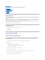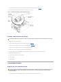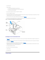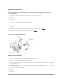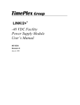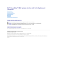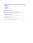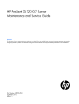
1
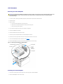
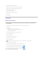
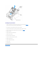
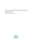
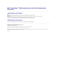
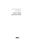
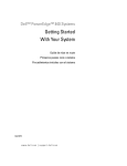
Dell™ PowerEdge™ 1800 Systems Service-Only Parts Replacement
Procedures
Before You Begin
Recommended Tools
Nonredundant Power Supply
Power Distribution Board
Control Panel
SCSI Backplane
System Board
Notes, Notices, and Cautions
NOTE: A NOTE indicates important information that helps you make better use of your computer.
NOTICE: A NOTICE indicates either potential damage to hardware or loss of data and tells you how to avoid the problem.
CAUTION: A CAUTION indicates a potential for property damage, personal injury, or death.
Abbreviations and Acronyms
For a complete list of abbreviations and acronyms, see the "Glossary" in the User's Guide.
Information in this document is subject to change without notice.
© 2004 Dell Inc. All rights reserved.
Reproduction in any manner whatsoever without the written permission of Dell Inc. is strictly forbidden.
Trademarks used in this text: Dell, the DELL logo, and PowerEdge are trademarks of Dell Inc.
Other trademarks and trade names may be used in this document to refer to either the entities claiming the marks and names or their products. Dell Inc. disclaims any
proprietary interest in trademarks and trade names other than its own.
July 2004 Back to Contents Page
Dell™ PowerEdge™ 1800 Systems Service-Only Parts Replacement Procedures
Before You Begin
Recommended Tools
Nonredundant Power Supply
Power Distribution Board
Control Panel
SCSI Backplane
System Board
Before You Begin
CAUTION: See your Product Information Guide for complete information about safety precautions, working inside the computer, and protecting
against electrostatic discharge.
The procedures in this document require that you remove the cover and work inside the system. While working inside the system, do not attempt to service
the system except as explained in this document and in the Installation and Troubleshooting Guide and the User's Guide available on support.dell.com. Always
follow the instructions closely, and ensure that you review all safety precautions in the Product Information Guide.
The Installation and Troubleshooting Guide contains information on system indicators, messages, and codes; system diagnostics; troubleshooting; parts removal
and replacement procedures; and jumpers, switches, and connectors.
The User's Guide contains information on the System Setup program.
Recommended Tools
You may need the following items to perform the procedures in this section:
l
Key to the bezel
l
#2 Phillips screwdriver
l
Wrist grounding strap
Nonredundant Power Supply
Removing a Nonredundant Power Supply
CAUTION: Only trained service technicians are authorized to remove the system cover and access any of the components inside the system. See
your Product Information Guide for complete information about safety precautions, working inside the computer, and protecting against
electrostatic discharge.
1.
Turn off the system, including any attached peripherals, and disconnect the system from the electrical outlet.
2.
Remove the bezel.
3.
Open the system:
a.
Loosen the three thumbscrews on the left-side cover.
b.
Grasp the cover at both ends and slide it toward the front of the system.
c.
Lift the cover away from the system.
4.
If your system is configured as a tower, lay the system on its right side.
5.
Remove the baffle/back fan assembly.
6.
Disconnect the power cables from the SATA hard drives or SCSI backplane, diskette drive, CD drive and any other installed drive.
7.
Disconnect the power cables from the system-board power connectors.
8.
Open the power-cable retainer clips and remove the power cables.
9.
10.
At the back of the system, remove the two screws that secure the power supply to the system. See Figure 1-1.
Use the power supply handle to carefully slide the power supply out of the system.
Figure 1-1. Removing and Installing a Nonredundant Power Supply
Installing a Nonredundant Power Supply
CAUTION: When sliding the power supply into the system, ensure that the cables are not between the front securing tabs and the securing slots.
1.
Slide the power supply into the system.
Ensure that the front securing tabs fully insert into the securing slots. See Figure 1-1.
2.
Install the two screws that secure the power supply to the back panel. See Figure 1-1.
3.
Connect the system-board power cables to the system-board power connectors.
4.
Place the power cables into the power-cable retainer clips and close the clips.
5.
Connect the power cables to the SATA hard drives or SCSI backplane, diskette drive, CD drive, and any other installed drive.
6.
Reinstall the baffle/back fan assembly.
7.
If the system is a tower, stand the system upright.
8.
Close the system.
9.
Reinstall the bezel.
Power Distribution Board
Removing the Power Distribution Board
CAUTION: Only trained service technicians are authorized to remove the system cover and access any of the components inside the system. See
your Product Information Guide for complete information about safety precautions, working inside the computer, and protecting against
electrostatic discharge.
1.
Turn off the system, including any attached peripherals, and disconnect the system from the electrical outlet.
2.
Remove the bezel.
3.
Open the system:
a.
Loosen the three thumbscrews on the left-side cover.
b.
Grasp the cover at both ends and slide it toward the front of the system.
c.
Lift the cover away from the system.
4.
If your system is configured as a tower, lay the system on its right side.
5.
Remove the baffle/back fan assembly.
6.
Remove all power cables from the system board power connectors and from their retainer clips, and the power cables from the SATA hard drives or SCSI
backplane, diskette drive, CD drive, and any other installed drive.
7.
Loosen the screw that secures the power distribution board to the chassis. See Figure 1-2.
8.
Slightly lift up the power distribution board, move it away from the retainers on the chassis wall, and then lift the unit out of the chassis.
Figure 1-2. Removing and Installing the Power Distribution Board
Installing the Power Distribution Board
1.
Align the power distribution board with the two chassis guides so that the right side of the power distribution board is flat against the chassis wall. See
Figure 1-2.
2.
Slide the power distribution board slightly down so the two bottom pegs on the power distribution board insert into their securing holes on the bottom
of the chassis. See Figure 1-2.
3.
4.
Tighten the screw to secure the power distribution board to the chassis. See Figure 1-2.
Reconnect all power cables to the system board power connectors and to their retainer clips, and the power cables from the SATA hard drives or SCSI
backplane, diskette drive, CD drive, and any other installed drive.
5.
Reinstall the baffle/back fan assembly.
6.
If the system is a tower, stand the system upright.
7.
Close the system.
8.
Reinstall the bezel.
Control Panel
Removing the Control Panel
CAUTION: Only trained service technicians are authorized to remove the system cover and access any of the components inside the system. See
your Product Information Guide for complete information about safety precautions, working inside the computer, and protecting against
electrostatic discharge.
1.
Turn off the system, including any attached peripherals, and disconnect the system from the electrical outlet.
2.
Remove the bezel.
3.
Open the system:
4.
a.
Loosen the three thumbscrews on the left-side cover.
b.
Grasp the cover at both ends and slide it toward the front of the system.
c.
Lift the cover away from the system.
If a 5.25-inch drive is installed in the peripheral drive bay, remove it. If that drive bay is empty, remove the chassis drive insert that covers the opening
of the empty bay.
5.
Open the control panel/chassis-intrusion switch cable retainer clip located below the peripheral drive bay. See Figure 1-3.
6.
Remove the three screws securing the control panel to the front of the system. See Figure 1-3.
7.
Disconnect the control panel and chassis-intrusion switch cables from the back of the control panel.
Figure 1-3. Removing and Installing the Control Panel
Installing the Control Panel
1.
Connect the control panel and chassis-intrusion switch cables to the back of the control panel.
2.
Replace the three screws to secure the control panel to the front of the system.
3.
Place the control panel and chassis-intrusion switch cables in the cable retainer clip, remove the cable slack between the clip and the control panel, and
then close the clip. See Figure 1-3.
4.
If you removed a 5.25-inch drive in step 4 of the previous procedure, reinstall the drive. If you removed the chassis drive insert in step 4 of the previous
procedure, reinstall the insert.
5.
If the system is a tower, stand the system upright.
6.
Close the system.
7.
Reinstall the bezel.
SCSI Backplane
Removing the SCSI Backplane
CAUTION: Only trained service technicians are authorized to remove the system cover and access any of the components inside the system. See
your Product Information Guide for complete information about safety precautions, working inside the computer, and protecting against
electrostatic discharge.
1.
Turn off the system, including any attached peripherals, and disconnect the system from the electrical outlet.
2.
Remove the bezel.
3.
Open the system:
a.
Loosen the three thumbscrews on the left-side cover.
b.
Grasp the cover at both ends and slide it toward the front of the system.
c.
Lift the cover away from the system.
4.
If your system is configured as a tower, lay the system on its right side.
5.
Remove the baffle/back fan assembly.
6.
Remove the SCSI hard drives from the drive bays.
7.
Remove the power and interface cables from the SCSI backplane connectors.
8.
Remove the four drive-cage retention screws on the front panel and remove the drive cage.
9.
Loosen the SCSI backplane-retention thumbscrew. See Figure 1-4.
10.
Slide the SCSI backplane to the right and then lift the backplane away from the drive cage.
Figure 1-4. Removing and Installing the SCSI Backplane
Installing the SCSI Backplane
1.
Insert the six securing tabs on the drive cage into the six securing tabs on the SCSI backplane.
2.
Slide the SCSI backplane to the left until it stops.
3.
Tighten the SCSI backplane-retention thumbscrew.
4.
Replace the drive cage and secure it with the four drive-cage retention screws.
5.
Replace the power and interface cables to the SCSI backplane connectors.
6.
Replace the SCSI hard drives into the drive bays.
7.
Replace the baffle/back fan assembly.
8.
If the system is a tower, stand the system upright.
9.
Close the system.
10.
Reinstall the bezel.
System Board
Removing the System Board
CAUTION: Only trained service technicians are authorized to remove the system cover and access any of the components inside the system. See
your Product Information Guide for complete information about safety precautions, working inside the computer, and protecting against
electrostatic discharge.
1.
Turn off the system, including any attached peripherals, and disconnect the system from the electrical outlet.
2.
Remove the bezel.
3.
Open the system:
a.
Loosen the three thumbscrews on the left-side cover.
b.
Grasp the cover at both ends and slide it toward the front of the system.
c.
Lift the cover away from the system.
4.
If your system is configured as a tower, lay the system on its right side.
5.
Remove the baffle/back fan assembly.
6.
Remove the expansion cards.
7.
Remove the expansion-card guide and the front fan.
8.
Disconnect all cables from the system board.
9.
Remove the memory modules.
NOTE: While removing the memory modules, record the memory module socket locations to ensure proper installation.
10.
Remove the heatsink(s) and microprocessor(s).
11.
Remove the four drive-cage retention screws on the front panel and remove the drive cage.
12.
Loosen the system-board retention thumbscrew located on the back panel. See Figure 1-5.
13.
Use the system-board tray handle to pull the system board tray forward. See Figure 1-5.
14.
Lift up the back end of the system board tray and slide it out of the chassis. See Figure 1-5.
Figure 1-5. Removing and Installing the System Board
Installing the System Board
1.
Holding the system-board tray at an angle, slide the front end of the tray into the chassis. See Figure 1-5.
The front end of the tray has the system-board tray handle attached to it.
2.
Lower the back end of the system-board tray until it lays flat in the chassis.
3.
Use the system-board tray handle to slide the tray towards the back of the chassis until it stops.
4.
Tighten the system-board retainer thumbscrew located on the back panel. See Figure 1-5.
5.
Replace the drive cage.
6.
Replace the heatsink(s) and microprocessor(s).
7.
Replace the memory modules.
8.
Reconnect all cables to the system board.
9.
Replace the expansion-card guide and the front fan.
10.
Replace the expansion cards.
11.
Replace the baffle/back fan assembly.
12.
Close the system.
13.
Reinstall the bezel.
Back to Contents Page