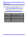
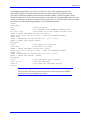
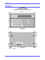
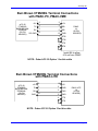
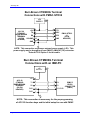
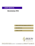
1
^1 USER MANUAL
^2 Accessory 20
^3 Burr Brown Alphanumeric Entry & Display
^4 3Ax-CTM200-xUxx
^5 October 15, 2003
Single Source Machine Control
Power // Flexibility // Ease of Use
21314 Lassen Street Chatsworth, CA 91311 // Tel. (818) 998-2095 Fax. (818) 998-7807 // www.deltatau.com
Copyright Information
© 2003 Delta Tau Data Systems, Inc. All rights reserved.
This document is furnished for the customers of Delta Tau Data Systems, Inc. Other uses are
unauthorized without written permission of Delta Tau Data Systems, Inc. Information contained
in this manual may be updated from time-to-time due to product improvements, etc., and may not
conform in every respect to former issues.
To report errors or inconsistencies, call or email:
Delta Tau Data Systems, Inc. Technical Support
Phone: (818) 717-5656
Fax: (818) 998-7807
Email: [email protected]
Website: http://www.deltatau.com
Operating Conditions
All Delta Tau Data Systems, Inc. motion controller products, accessories, and amplifiers contain
static sensitive components that can be damaged by incorrect handling. When installing or
handling Delta Tau Data Systems, Inc. products, avoid contact with highly insulated materials.
Only qualified personnel should be allowed to handle this equipment.
In the case of industrial applications, we expect our products to be protected from hazardous or
conductive materials and/or environments that could cause harm to the controller by damaging
components or causing electrical shorts. When our products are used in an industrial
environment, install them into an industrial electrical cabinet or industrial PC to protect them
from excessive or corrosive moisture, abnormal ambient temperatures, and conductive materials.
If Delta Tau Data Systems, Inc. products are directly exposed to hazardous or conductive
materials and/or environments, we cannot guarantee their operation.
^1
USER MANUAL
Accessory 20
Table of Contents
INTRODUCTION .......................................................................................................................................................1
ACC-20 CABLES ........................................................................................................................................................3
PMAC SETUP .............................................................................................................................................................5
TERMINAL SETUP ...................................................................................................................................................7
PROGRAMMING FUNCTION KEYS.....................................................................................................................9
USING ALPHANUMERIC KEYBOARD ..............................................................................................................11
An Example of Acc-20 Use within a PMAC Program............................................................................................11
Use of Function Keys..........................................................................................................................................11
Special Use of PMAC’s P0 Variable ..................................................................................................................11
GRAPHICS ................................................................................................................................................................13
Table of Contents
i
Accessory 20
ii
Table of Contents
Accessory 20
INTRODUCTION
PMAC's Accessory 20 (ACC-20) is a small size serial communication terminal manufactured by Burr
Brown (model # CTM200G). This model replaces the TM2500 terminal previously used. ACC-20 is
typically used in applications where it is more convenient to use a small self-contained keyboard/display
terminal (rather than a Host based computer) to communicate to the PMAC card via its serial connector.
The unit may be used either as a hand-held terminal or it may be rack mounted. The terminal includes a
large 16-character liquid crystal display. The sealed keyboard has 24 keys consisting of numerical keypad
or optional alphanumeric keypad. By using the "SHIFT" key, the six function keys are mapped to give
access to 18 functions. CTM200G runs on standard +5V power supply that is brought in through the
supplied RS232 flat cable for PMAC-PC, PMAC-VME and the new PMAC-LITE. For the STD32 bus
version of PMAC, a separate power supply is required.
For physical dimensions and mounting information, refer to the enclosed diagram.
Introduction
1
Accessory 20
2
Introduction
Accessory 20
ACC-20 CABLES
Depending of the specific version of PMAC there are three different RS232 connection cables available.
These cables may be ordered as ACC-20 options.
•
•
•
ACC-20 Option 1 is the RS232 cable for the connection of ACC-20 with PMAC-PC and PMACVME.
ACC-20 Option 2 is the RS232 cable for the connection of ACC-20 with PMAC - STD32.
ACC-20 Option 3 is the RS232 cable for the connection of ACC-20 with PMAC-LITE.
ACC-20 Cables
3
Accessory 20
4
ACC-20 Cables
Accessory 20
PMAC SETUP
To use the hand held terminal with PMAC, the following modifications need to be made:
•
•
On PMAC-VME, PMAC-PC, and PMAC-LITE install jumper E8 to allow +5V supply from PMAC
to drive the CMT200G. (This jumper is installed by default).
Set I3 (I/O handshake Control I-variable) to zero.
PMAC Setup
5
Accessory 20
6
PMAC Setup
Accessory 20
TERMINAL SETUP
Before the first time use of ACC-20 with PMAC, it should be setup correctly using the Setup procedure
described in the CTM200G Manual. This Manual is supplied with the purchase of ACC-20. Chapter 3 of
the Manual describes the setup procedure. The setup parameters should then be saved with the SAVE
command (F8 or SHIFT F2). Once saved the terminal block may be connected to PMAC's serial
communication connector. Note that ACC-20’s options 1 to 3 provide the appropriate connecting cable
for the various versions of PMAC. Refer to the enclosed wiring diagrams.
NOTE:
To carry out the initial (one time) setup procedure, you need to communicate with
ACC-20 directly through a serial host (other than PMAC). This may be a regular
RS232 terminal or a PC based terminal emulator. Once the setup parameters are
saved in the memory of ACC-20, it can be connected to PMAC.
The following setup parameters should be chosen for operation with PMAC (refer to section 3.3 of the
CTM200 Manual):
Host Baud...
Host Port Data...
Host Port Stop Bit...
Host Handshake...
Keyboard enable...
Keyboard repeat.
Keyboard click...
Keyboard Setup...
Enter Key Control...
Display Flashing...
Display Cursor...
Autowrap.
Local Enable...
Newline.
Delay Rate...
Terminal Setup
User selectable to match PMAC's selected by jumpers E44 to E47.
Should be set to "8 NONE".
Should be set to "1" (Factory default).
Should be set to "None" (Factory default).
Should be set to "ON" (Factory default).
Should be set to "ON" (Factory default).
Should be set to "ON" (Factory default).
Should be set according to the users needs.
Should be set to CR/LF.
Should be set to according to the users needs.
Should be set to according to the users needs.
Should be set to "OFF" (Factory Default)
Should be set to "ON" (this is not Factory Default).
Should be set to "OFF" (Factory Default)
0 ms (Factory Default).
7
Accessory 20
8
Terminal Setup
Accessory 20
PROGRAMMING FUNCTION KEYS
Refer to section 5.1 of the CTM200G manual for general host commands. In particular, the function keys
may be programmed through the "m" command by issuing
<ESC>m<function key number>TEXT <STX> (see page 5-17 of the CTM200G Manual).
Each function key may be programmed to send various ASCII strings (or text) to PMAC (the maximum
number of characters is limited to six). Example: To program F1 to send "J+" to PMAC you would have
to have (previously) programmed the CTM200G by sending to its RS232 port the following sequence:
<ESC>m01J+<STX>
Here 01 refers to function key 1 (F1).
Note:
<STX> is usually mapped to the "Ctrl B" character code on most PC computers.
All together, there are 18 function keys. Once programmed, the key definitions are automatically saved
and need not be re-entered upon subsequent power up. To access F7 to F12, a Shift key should be pressed
once before pressing keys F1 to F6 respectively. For F13 to F18, press the Shift key twice before pressing
F1 to F6.
Programming Function Keys
9
Accessory 20
10
Programming Function Keys
Accessory 20
USING ALPHANUMERIC KEYBOARD
Refer to section 9.1 of the CTM200G Manual for the description of the alphanumeric keys' access. The
left letters are accessed by pressing the shift key once before pressing the corresponding key. The right
letters are accessed by pressing the shift key twice.
Example: To read the value of the M-variable 100 the following keys are pressed
Shift7100 <Enter>
An Example of Acc-20 Use within a PMAC Program
Use of Function Keys
In most applications of ACC-20, the functions keys are pre-programmed to correspond to the definition of
the most commonly used PMAC on-line command strings. Example: To program the function key F2 to
correspond to the PMAC command string "&1b2r" (meaning in coordinate system 1 begin at the top of
program 2 and then run), the following commands need to be sent to the CTM200G from the PC prior to
its connection to the PMAC card:
<ESC>m02&1b2r<STX>
Once this function (F2 is this case) has been programmed, every time it is pressed, the ASCII string for
"&1b2r" is sent to PMAC. According to specific applications, the 18 function keys may be programmed
to correspond to the most widely used command strings.
Special Use of PMAC’s P0 Variable
Of the 1024 P-variables of PMAC, P0 has a specific feature, which is very useful for use with the
Accessory 20. This variable's content (stored internally as a 48-bit floating number) is automatically
updated whenever a number is entered from the current PMAC Host Port followed by <CR> (carriage
return). When the CTM200G acts as the PMAC host, then the value of P0 would correspond to the latest
numerical entry from the terminal when followed by a <CR>. A typical utilization of this feature would
be to enter commanded positions, feedrates, move times etc. into PLC or Motion programs. The following
programming example demonstrates the use of P0 entries via the CTM200G's keyboard:
Using Alphanumeric Keyboard
11
Accessory 20
This program demonstrates the use of the p-variable zero ;(p0) within a motion program. P0 is
specifically designed to contain the latest numerical entry from the host. This feature allows the
processing of numerical constants entered from the keyboard to PMAC’s buffered programs. In this
particular example, P0 is used to enter the x and the y vectors entries in a motion program. Moreover, the
vectors are restricted to be greater or equal to 0.001 units of length. The absolute value of this unit would
have been previously defined using the PMAC’s axes definition statements.
CLOSE
OPEN PROG 1
INC
; RELATIVE MOVES
F1000
; SET FEEDRATE FOR STANDARD BLENDED MOVE
N10 P0=0.0009
; INITIALIZE P0 TO AN ILLEGAL VECTOR SIZE
SENDS " ENTER THE NEXT VECTOR FOR X-AXIS "
WHILE (P0<=0.001 OR P0>=-0.001) ; WAIT FOR KEYBOARD ENTRY
DELAY 2000
SENDS " MAGNITUDE OF VECTOR MUST BE = OR > 0.001"
SENDS " ENTER THE VECTOR AGAIN"
END WHILE
P1=P0
; SAVE ENTRY FOR X-VECTOR
P0=0.0009
; INITIALIZE P0 AGAIN
SENDS " ENTER THE NEXT VECTOR FOR Y-AXIS"
WHILE (P0<=0.001 OR PO>=-0.001) ; WAIT FOR KEYBOARD ENTRY
DELAY 2000
SENDS " MAGNITUDE OF VECTOR MUST BE = OR > 0.001"
SENDS " ENTER THE VECTOR AGAIN"
END WHILE
P2=P0
; SAVE THE ENTRY FOR Y-VECTOR
X(P1) Y(P2)
; NOW MAKE THE MOVE
GOTO 10
; LOOP BACK FOR THE NEXT VECTOR
CLOSE
Note
The use of P0 in the above program has saved the user from using several SHIFT
keys followed by many character key entries.
12
Using Alphanumeric Keyboard
Accessory 20
GRAPHICS
Acc-20
Burr-Brown CTM200G
Alphanumeric Entry and Display Unit
4.00 in.(101.6 mm)
7.00 in.(177.8 mm)
Shift
Delete
1
2
3
A B
C D
E F
4
5
6
G H
I J
K L
7
8
9
M N
O P
Q R
Space
S T
-
0
U V
W X
Enter
Y Z
Front View
.38in.
(9.65mm)
.75 in.
(19.05mm)
.38in.
(9.65mm)
.75 in.
(19.05mm)
Mounting Holes
Main Port
.75 in.
(19.05mm)
.75 in.
(19.05mm)
.38in.
(9.65mm)
1.25 in.
(31.75mm)
Graphics
.25 in.
(6.35mm)
Rear View
.38in.
(9.65mm)
13
Accessory 20
Burr-Brown CTM200G Terminal Connections
with PMAC-PC, PMAC-VME
+5V
ACC-20
CTM200G
TX
BURR-BROWN
RX
TERMINAL
(26-PIN
HEADER) SIG GND
2
2
3
3
RD/
5
5
SD/
13
13
GND
7
RTS/
9
CTS/
8
CTS
10
+5V
PMAC
J4
(26-PIN
HEADER)
RTS
Install E8 to allow
+5V out from PMAC
NOTE: Order ACC-20 Option 1 for this cable
Burr-Brown CTM200G Terminal Connections
with PMAC-LITE
ACC-20
CTM200G
BURR-BROWN
TERMINAL
(26-PIN
HEADER)
+5V
TX
RX
GND
2
10
3
5
RXD/
5
3
TXD/
13
9
GND
4
CTS
6
RTS
+5V
PMAC-LITE
J4
(10-PIN
HEADER)
NOTE: Order ACC-20 Option 3 for this cable
14
Graphics
Accessory 20
Burr-Brown CTM200G Terminal
Connections with PMAC-STD32
+5V
SUPPLY
GND
2
4
ACC-20
3
TX
CTM200G
BURR-BROWN
RX 5
TERMINAL
(26-PIN
SIG GND 13
HEADER)
GND 1
1
RXD/
2
TXD/
3
GND
+5V
CTS
PMAC-STD32
J1
(5-PIN
HEADER)
NOTE: This connection requires an external power supply (+5V). This
power supply may be brought out from PMAC's JMACH1 (J8) connector.
Order ACC-20 Option 2 for this cable.
Burr-Brown CTM200G Terminal
Connections with an IBM-PC
+5V
SUPPLY
+5V
ACC-20
CTM200G
BURR-BROWN
TERMINAL
(26-PIN
HEADER)
GND
2
3
3
5
2
GND
13
7
GND
1
TX
RX
RX
IBM-PC
RS232
TX
CONNECTOR
(DB25)
SIG GND
NOTE: This connection is necessary for the preprogramming
of ACC-20 function keys and its initial setup for use with PMAC
Graphics
15