1
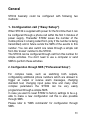
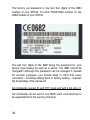
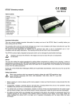
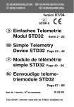
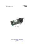
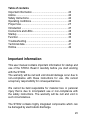
Table of contents
Important information .....................................................23
Advice ............................................................................24
Safety Instructions .........................................................24
Operating conditions ......................................................26
Proper Use.....................................................................27
Introduction ....................................................................27
Connectors and LEDs....................................................28
Startup ...........................................................................29
Function .........................................................................33
Troubleshooting .............................................................40
Technical data................................................................41
Hotline............................................................................42
Important information
This user manual contains important information for startup and
use of the STD32. Read it carefully before you start working
with the STD32.
The warranty will be null and void should damage occur due to
non-compliance with these instructions for use. We cannot
accept any responsibility for consequential loss.
We cannot be held responsible for material loss or personal
injury that is due to incompetent use or non-compliance with
the safety instructions. The warranty will be null and void in
such circumstances.
The STD32 contains highly integrated components which can
be damaged by electrostatic discharge.
23
Therefore only touch the STD32 on the edges
and avoid to touch the pins of components on
the board.
Advice
The one who makes the module operational by adding further
components or putting it into a housing, is seen as
manufacturer according to DIN VDE 0869 and obliged to hand
out all necessary documents with the device and to indicate his
name and address. Devices which are made out of modules
have to be considered as an industrial product from the safety
perspective.
During use of the STD32 Short Messages (SMS) can be
generated automatically. Costs may occur for you by this SMS
traffic.
Safety Instructions
•
24
When using products which are exposed to
electric voltage the valid VDE-regulations have
to be observed. Especially VDE 0100, VDE
0550/0551, VDE 0700, VDE 0711 and VDE
0860 are applicable.
Before opening of a device always pull the mains adapter
or make sure that the device is disconnected from the
power supply.
•
•
•
•
•
•
•
Components, modules or devices have to be build into a
housing before they are put into operation. During
installation they should not be connected to any power
supply .
You should only use tools on components, modules or
devices if they are disconnected from the power supply
and the electric charge, which may still be stored in some
components, inside the device has been discharged.
All cables and wires which are energized and connected
to the device, the module or components have to be
checked regularly for any damage of the isolation shield
or fractures of the cables. If the supply cables are visibly
damaged the device has to be taken out of operation
immediately until the faulty cable has been exchanged.
When using components or modules it is necessary to
strictly observe the specification given in the
corresponding description of these components.
If a description for a private end-customer not clearly
states which electric data is valid for a component or a
module, how to wire the device, which external
components or additional devices can be connected or
which parameters these components are allowed to have,
a specialist must be contacted.
Before putting a device into operation, it has to be
clarified, whether this device or module is meant for the
field of application. In case of doubt ask specialists or the
manufacturer of the device.
Please note that we are not responsible for any errors in
usage or connection. Therefore we cannot accept any
responsibility for consequential loss.
25
•
•
•
Devices which operate with >35 Volt have to be
connected by a specialist.
Before putting the device into operation it should be
checked that there is no current leakage on the housing.
In case that measurements with the opened housing are
necessary, an isolating-transformer has to be integrated
for saftey reasons. Alternatively the voltage can be
supplied by an appropriate power supply which complies
with the safety regulations. All wiring work has to be done
in a voltage free state only.
Operating conditions
•
•
•
•
•
•
•
•
26
Operate the STD32 only with a supply voltage between 532V and have in mind the polarity! (see picture1) The
power supply has to deliver at least 500mA. If you use a
mains adapter for power supply it has to be conform with
the VDE regulations.
Devices with an operating voltage >35 Volt have to be
installed by a specialist observing the VDE regulations.
Loads connected to the device are not allowed to exceed
1000W per relay.
The maximum voltage is 250V AC (alternating current)
The maximum switching power per relay is 6A
(depending on the width of the PCB tracks)
No special operation position of the device has to be
observed.
When installing the device make sure that the supply
cable has a sufficient diameter
During operation the temperature has to be between -20°
and 55° Celsius.
•
•
•
•
•
•
•
•
In case of condensation allow a period of about 2 hours
for acclimatisation.
Keep away the device from flower vases, bath tubs,
washbasins, liquids etc.
The device is meant for operation in dry and clean rooms.
Protect the device from humidity, spray water and heat.
Do not expose the device to heavy vibrations.
Do not operate the device in areas where are or could be
inflammable gas, vapours or dust.
The unit may only be repaired by a specialist.
Only original parts have to be used when repairing the
unit. The use of differing spare parts can cause serious
material loss or personal injury.
Proper Use
The device is designed for the remote switching of devices via
the GSM network as well as the remote retrieval of status
information of the inputs and the generation of SMS messages
after status has changed at the inputs. A different utilisation of
the device other than the one described above is not allowed.
Introduction
The STD32 is a telemetry module which is easy to install and
simple to use.
With the STD32 you can control two relays and monitor the
status of two digital inputs with one or several common mobile
phones.
27
Apart from the STD32 you only need a valid SIM Card of any
network provider (GSM 900 / 1800 MHz).
While using prepaid SIM-cards one shall always keep himself
aware of the amount left on the card, so that in case of alarms
a SMS could be sent.
Typical fields of application are the opening of (garage) doors,
switching on and off light and alarm devices as well as
generating alarm messages (SMS) or the retrieval of
information from door sensors, movement sensors or level
sensors etc.
Connectors and LEDs
IN1
Relay Relay
1
2
IN2
P
W
R
ANT
STD32
Relays Inputs
L1 L2 L3 L4
Status LEDs
figure 1
28
GSM engine
GSM
LED
As described in figure 1 the STD 32 has four pairs of screw
terminals. Two pairs (In1, In2) are inputs to two optocouplers.
The other two pairs (Relay1, Relay2) are outputs (switches) of
the 2 relays of the STD32.
PWR: connect the supply voltage of the STD32 here.
ANT: connect the GSM antenna here.
When the engine is booked into the GSM network the GSM
LED is flashing once every 2 seconds.
The status LEDs show the status of the inputs and outputs. L1
and L2 are on if the corresponding relay is activated. L3 and L4
signal the status of the optocoupler inputs IN1 and IN2.
Please observe the maximum output voltage of the relays and
the maximum input voltage of the inputs! In the following
chapter „Startup“ you will find further information on this.
Startup
You need an activated SIM card of a GSM network provider.
The PIN of this card has to be set to „0000“. To change the PIN
you can use a common mobile phone. The instructions how to
change the PIN are described in the manual of your mobile
phone.
29
If you use a SIM card with a PIN different from „0000“ in
the STD32, the STD32 will use a „wrong“ PIN after every
restart. After the third trial your SIM card will be blocked. In
this case you need to use the „Super-PIN“ or „PUK“ to
assign a new PIN to your card. Please look into the user
guide of your mobile phone. There you find how to use the
PUK to de-block the SIM card.
Should you wish to use a SIM card which does not require a
PIN, this is also possible and the STD32 recognizes this and
will behave accordingly.
Before connecting the supply voltage to the STD32 please
insert the SIM card into the SIM card holder on the backside of
the STD32: To open the SIM card holder move it sideward and
flip it open; insert the card (mind the orientation) and close it
again. To fix it move the top sideward in opposite direction.
Connect the antenna, if not already done.
Now connect the power supply. Shortly after that the GSM LED
will shine constantly. Now the STD32 will automatically try to
connect to the GSM network. As soon as this is done, the GSM
LED will be flashing once every 2 seconds.
30
General
STD32 basically could be configured with following two
methods:
1. Configuration call (“Easy Setup”)
When STD32 is supplied with power for the first time then it can
be configured through a phone call within the first 3 minutes of
power supply. Thereafter STD32 saves the number of the
mobile phone it is being called from (only if the number is being
transmitted) and in future sends the SMS of the events to this
number. You can also switch one relais through a simple call
from this ‘known’ number to the STD32.
The STD32 can be configured through call from this number for
simple activities. You don’t need to use a computer or send
SMS to perform these activities.
2. Configuration through SMS (“Professional Setup”)
For complex tasks, such as switching both outputs,
configurating additional phone numbers which are allowed to
trigger an output or receive alarm messages, changing
standard text, changing input pulse time and many other
complex parameters the STD32 can be very easily
programmed through a simple SMS.
In case you want to reset STD32 to factory settings to be e.g.
able to make a new configuration call this is also possible
through SMS.
Please refer to “SMS commands” for configuration through
SMS.
31
Configuration call
Wait until the GSM LED is flashing. Now take the mobile phone
with which you want to control the STD32 and call the phone
number of the SIM card which is inside the STD32. The STD32
will accept the call and cancel it a few seconds later. During
this call, a four digit DTMF sequence is send to the caller and
you will hear them on your mobile phone. With this call the
STD32 is configured to the mobile phone. Pay attention that
your mobile phone is transmitting the phone number which
means that the GSM functions “incognito” or “private call” are
disabled. You can change this configuration by inserting the
SIM card into a mobile phone. To test the setting you can call a
different mobile phone; there your phone number or name
should be displayed.
In case the STD32 will be separated from the power supply by
a power failure it will automatically send a SMS with the text
„START-UP ALARM“ to the preconfigured telefone number as
soon as the power supply is established again.
Note: The red LEDs of the STD32 will blink cyclically as
long as the STD32 is not configured by a configuration call
or a SMS (factory setting). After 3 minutes the device is
switching off. If you switch it on again afterwards the
STD32 is again expecting the configuration.
32
Function
After having configured the STD32 the following functions are
available (see chapter „Startup“):
Switching by phone call
After having completed the configuration please call the phone
number of the SIM card which is inside the STD32. Please pay
attention that your phone number is transmitted by your
mobile phone (see chapter Configuration call). Now the
relay should switch for a certain time (Factory setting is 1
second). The status LED for relay 1 is shinging during that.
Generate an alarm SMS
Connect 12V (factory setting) to an input for one second and
mind the polarity. An alarm SMS will be sent to your mobile
phone
Send SMS commands
You can control outputs or configure the STD32 by sending
SMS to it.
Those SMS have the following format which is described
below:
In order to avoid unauthorized usage of the STD32 it is
protected with a password. Every SMS to the STD32 must start
with a 4-letter password.
33
The factory set password is the last four digits of the IMEI
number of your STD32. You find YOUR IMEI number on the
GSM module of your STD32.
The last four digits of the IMEI being the password for your
device must always be kept as a secret. The IMEI cannot be
changed!!! Although the password can be changed if needed
for security purposes, you should keep in mind that every
command – including setting back to factory setting – requires
the knowledge of the password.
All commands (except R: and ST?) must end with a full stop (.)!
All commands can be sent in one SMS; each command has to
be separated from the next by a full stop.
34
The parameters for the seconds can have 1-5 digits. Valid
parameters are e.g. 1, 90 or 99999. No leading “Zeros” have to
be added. Example: “O1:90” stands for 90 seconds.
Please observe the difference between the figure ‘0’ and
the letter ‘O’!. (O1ON. Contains twice the letter O; V1:0.
contains once the figure 0)
Basic functions
•
•
•
When you call the STD32 from the configured mobile
phone the relay 1 switches for one second. Immediately
after that the STD32 sends a reply SMS with the actual
status of the inputs and outputs.
When the digital input IN1 is activated for one second, the
STD32 sends a SMS with the text „EVENT ALARM1“ to
the preconfigured phone number
When the digital input IN2 is activated for one second, the
STD32 sends a SMS with the text „EVENT ALARM2“ to
the preconfigured phone number.
Switching through SMS
•
•
After the STD32 has received a SMS with the text
„O1ON“ (Output 1 ON) from the configured mobile phone,
the relay 1 switches for one second. With the SMS
„O2ON“ relay 2 switches for one second.
If the switching time has been set to 0 by a configuration
SMS the relays switch permanently.
35
Configuration SMS
•
•
•
•
•
•
•
36
A SMS with the text „O1:xxxxx“ or „O2:xxxxx“ (xxxxx =
seconds) configures the switching time of the relays. The
STD32 saves these settings so that they are still available
after the supply voltage has been restored.
If the switching time has been set to 0 by a configuration
SMS the corresponding relay switches permanently at
every call. If the relay has been active before it will
afterwards
be
inactive
and
vice
versa.
In this case a SMS with the text „O1ON“ from the
configured mobile phone switches the relay 1
permanently on. A SMS with „O1OFF“ permanently
switches off relay 1. Relay 2 is reacting accordingly to
SMS messages with „O2ON“ and „O2OFF“.
With a SMS with the text „I1:xxx“ or „I2:xxx“ (xxx =
seconds) you can configure the time the inputs have to be
activated before the STD32 sends out an alarm SMS.
A SMS with the text „V1:x“ or „V2:x“ (x = 1 or 0) can
change the polarity of the inputs. If x=1 an alarm SMS will
be sent in case the input has not been activated for the
configured time.
You can activate or deactivate the Start up SMS (STARTUP ALARM) with the SMS „S:x“ (x = 1 or 0).
The SMS „R:“ is setting the STD32 back to the factory
settings.
To get a feedback of the actual status of the inputs and
outputs
just
send
a
SMS
with
„ST?”.
•
•
•
•
•
The SMS „A1:xxx“ or „A2:xxx“ (x = seconds) sets the
delay after which a reply SMS is sent after an output has
been activated. This can be helpful if you want to switch
something on or off and would like to measure the result
of this output control with one of the inputs of the STD32.
Therefore the new status after the switching of the output
is transmitted.
With the “PN:<4digit password>.” command the password
can be changed. The password can include letters and
figures but no special characters are allowed. All letters
have to be in capital. The standard password (factory
setting) is the last 4 digits of the IMEI (see chapter SMS
Commands).
Four additional alarm numbers can be defined using C2: C5: commands. These numbers are allowed to set relay 1
by a call and they are informed via SMS in case of
event1,2 and start up. These numbers are not allowed to
send
configuration
SMS.
If an alarm number is given in international format,
the number must start with ‘+’.
You can generate an extended clip list of several 100 clip
numbers. These numbers stored in the clip list are
allowed to switch relay 1. Use “CL:” to generate the clip
list and add further phone numbers. With “CD:” you can
delete a phone number from the list.
The texts of the event or start up SMS can be changed
with the commands “E1:<text1>”, “E2:<text2>” and
“PT:<startup text>”. The message length must not exceed
64 characters. Do not use command syntax inside a
message text. The ‘.’ is the terminating character of
the text. Each new text must be sent in a separate
SMS.
37
Table of SMS Commands
Factory settings
Status of I/Os
Start SMS on/off
Relais 1 on
Relais 1 off
Relais 2 on
Relais 2 off
Switching time Relais 1
Switching timeRelais 2
Delay before reply (Relais 1)
Delay before reply (Relais 2)
Time of activation Input 1
Time of activation Input 2
Invert Input 1
Invert Input 2
2. alarm number
3. alarm number
4. alarm number
5. alarm number
new password
event text 1
event text 2
start up Text
add clip to the extended clip list
remove clip from the extended clip
list
38
R:
ST?
S:1. / S:0.
O1ON.
O1OFF.
O2ON.
O2OFF.
O1:xxxxx. (seconds)
O2:xxxxx. (seconds)
A1:xxx. (seconds)
A2:xxx. (seconds)
I1:xxx. (seconds)
I2:xxx. (seconds)
V1:x. (x= 1/0 )
V2:x. (x= 1/0 )
C2:<number>.
C3:<number>.
C4:<number>.
C5:<number>.
PN:xxxx.
E1:<text>.
E2:<text>.
PT:<text>.
CL:<nummer>.
CD:<nummer>.
Examples for SMS Commands
Start up Alarm off, Relay 1 on, Relay 2 off, time of activation of
input 1: 5 sec.:
SMS: 2759 S:0.O1ON.O2OFF.I1:5.
Switching time of relay 1 = 90 seconds:
SMS: 2759 O1:90.
Reset settings to factory settings:
SMS: 2759 R:
Configuration of the second alarm number:
SMS: 2759 C2:+491721234567.
Deleting a alarm number:
SMS: 2759 C2:.
Configuration of a new password:
SMS: 2759 PN:AB12.
Adding a new clip to the extended clip list:
SMS: AB12 CL:491721234567.
Removing the clip from the extended clip list:
SMS: AB12 CD:491721234567.
39
Troubleshooting
Problem
GSM LED stays
dark
GSM LED blinks
twice cyclically
Possible
reason
No supply
voltageNo SIM card /
Improper contact
with SIM card
GSM LED blinks
thrice cyclically
PIN is not “0000”
GSM LED
constantly on
No GSM
network
available / no
antenna
connected
No configuration
GSM LED dies
after 3 minutes
STD32 does not
react on
configuration call
(not accepting the
call)
STD32 does not
react on
configuration SMS
40
Device is
already
configured
Wrong IMEI
number in the
SMS / SMS not
yet delivered
Solution
Connect power
supply
Insert SIM card
properly or
carefully clean
contact area of
SIM card
Change SIM
card’s PIN to
„0000“
Connect antenna
/
Change antenna
position
Make
configuration call
Set back to
factory settings
Check IMEI
number. / Wait
until SMS is
delivered
STD32 does not
react on SMS, or
call, although
booked to the
network
Both red LEDs
blink consecutively
The mobile
phone does not
transmit the
phone number
(„Incognito“)
No configuration
call received by
STD32
Activate the
transmission of
the phone
number in your
mobile phone
Makw a
configuration call
Technical data
•
•
•
•
•
•
•
•
•
GSM:
Dual
Band
EGSM
900/1800
MHz
Compatible with ETSI GSM Phase 2+ Standard
Output power:
Class 4 (2W @ 900 MHz)
Class 1 (1W @ 1800 MHz)
Temperature range: -20°C - +55°C
Weight approx. 100 gramme
Dimensions: 100x53x25 mm (lxwxh)
Supply voltage: 5-32V
Idle current:15mA, Peak up to 500mA
Max. output voltage: 6A
Max. voltage: 250V AC
Input voltage (digital inputs)
logic 1:
12 V
logic 0:
0V
input current:
10mA
41
Hotline
In case of technical problems or questions concerning the
STD32 our hotline is available for you:
Monday – Friday:
Technical Hotline:
9 am – 5pm
+49 (0)89 / 450292-11
For all other questions please call
Sales
+49 (0)89 / 450292-0
Issue: Juli 2004. Subject to change without notice!
42