1
EDK II Platform Description (DSC)
File Specification
December 2014
Revision 1.24
EDK II DSC File Spec.
Acknowledgements
THIS SPECIFICATION IS PROVIDED "AS IS" WITH NO WARRANTIES WHATSOEVER, INCLUDING ANY
WARRANTY OF MERCHANTABILITY, NONINFRINGEMENT, FITNESS FOR ANY PARTICULAR PURPOSE, OR
ANY WARRANTY OTHERWISE ARISING OUT OF ANY PROPOSAL, SPECIFICATION OR SAMPLE. Intel products
are not intended for use in medical, life saving, or life sustaining applications.
Intel may make changes to specifications and product descriptions at any time, without notice.
Designers must not rely on the absence or characteristics of any features or instructions marked "reserved" or
"undefined." Intel reserves these for future definition and shall have no responsibility whatsoever for conflicts or
incompatibilities arising from future changes to them.
A license is hereby granted to copy and reproduce this specification for internal use only.
No other license, express or implied, by estoppel or otherwise, to any other intellectual property rights is granted
herein.
Intel disclaims all liability, including liability for infringement of any proprietary rights, relating to use of information in
this specification. No license, express or implied, by estoppel or otherwise, to any intellectual property rights is granted
herein.
This specification is an intermediate draft for comment only and is subject to change without notice. Readers should
not design products based on this document.
*Other names and brands may be claimed as the property of others.
Copyright ©2006 - 2013 Intel Corporation. All rights reserved.
ii
December 2014
Version 1.24
EDK II DSC File Spec.
Revision History
Revision
Revision History
Date
1.0
Initial release .
December 2007
1.1
Updated based on errata
August 2008
1.2
Updated based on enhancement requests
June 2009
1.21
Updated based on errata and enhancement requests
• Added language filters: RFC_LANGUAGES and
ISO_LANGUAGES
• Added Note that a reserved macro name,
MDEPKG_NDEBUG
• Definitions in DSC file are now global to both DSC and
FDF files
• PCD Values may be constructed using C-style
expressions provided the result of the expression matches
the datum type of the PCD
• FeatureFlagExpression is now defined as a C-style
expression using C relational, equality and logical numeric
and bitwise operators and/or arithmetic and bitwise
operators that evaluate to a value that matches the Datum
Type of the PCD. Precedence and associativity follow C
standards
Spec changed to match existing formats:
• SUPPORTED_ARCHITECTURES and
BUILD_TARGETS use the pipe “|” separator, not the
comma character
March 2010
1.22
Errata and grammatical changes
May 2010
Version 1.24
December 2014
iii
EDK II DSC File Spec.
1.22 w/
Errata A
iv
Updates:
• Updated to support UEFI version 2.3.1 and updated spec
release dates in Introduction
• Clarify UEFI’s PI Distribution Package Specification
• Standardize Common data definitions for all specifications
• Grammatical, formatting and spelling changes
• Replaced “should” with wording saying that it is
“recommended”
• Remove “$(WORKSPACE)/” from the examples
• Removed content that only applied to the EDK build
system and EDK DSC format that is not used by the EDK
II build system
• Rename $(TAGNAME) to $(TOOL_CHAIN_TAG) and
remove the synonym $(TOOLCHAIN)
• Added TIME_STAMP_FILE back into the [Defines]
section
• Added the SOURCE_OVERRIDE_PATH for EDK
components (not valid for EDK II modules)
• Added EDK_GLOBAL as a special type of MACRO
statement only valid for EDK INF files
• Added VPD_TOOL_GUID in [Defines] section
• Allow the OUTPUT_DIRECTORY path to be either
absolute or relative to the WORKSPACE
• Revised EBNF for PCD sections to allow more precise
definitions
• Added EBNF for <Extension>
• Added EBNF for <Keyword> 3.9.x and renamed
<LibInstanceMap> to <ClassInstanceMap> in 3.10.
• Require PCDs to use the full name, removing
ShortPcdName from definitions
• Updated to clarify that a PCD cannot be used in multiple
methods; a PCD can ONLY be used in one way, Also, the
<PcdsDyanmic> sub section can only be used if the PCD
is not listed in any of the common sections; All instances
of the PCD must then use this method
• Revised grammar and include additional clarifications for
conditional directives and macro usage; clarify PCD
usage in conditional directives and expressions - the
$(PcdName) format is never used
• Fixed VPD PCD format; allow the MAX size value to use a
wildcard character & added info about where it comes
from; added appendix for BPDG file formats; renamed
some PCD example tokens and PCD names; cleaned up
the sample DSC file
• Removed invalid [|MaximumDatumSize] for HII PCDs in
section 2.2.13.3
• Document where VOID* lengths are derived from when
not specified in the DSC file
• Clarify that C data arrays must be byte arrays for PCD
value fields; both C format and Registry format GUIDs
structures are not permitted in VOID* PCD value fields
• Removed the SET statement, used to define values for
PCDs from all sections of this document. The SET
statement is only valid in FDF files
December 2014
December 2011
Version 1.24
EDK II DSC File Spec.
1.22 w/
Errata A
(Cont.)
• Specify how sections are merged during parsing of the
EDK II meta-data files
• Specifically state how [BuildOptions] content should be
applied; define how [BuildOptions] sections are merged
• Clarify where macros are evaluated/expanded
• Provide rules for how macros can be used in different
BuildOptions sections
• Clarify Macros in [Defines] section can automatically be
used in FDF files.
• Removed references to system environment variables in
the Macros section
• Updated conditional rules in 2.2.7 for how to use macro
and PCDs; change #elif to #elseif in 3.2.3 to match
implementation
• Added the “IN” operator as an Equality Operator - added
description and restriction of it’s usage using
<MemberExpression>
• Corrected [Defines] section information, changed format
of for paths, directories and files in common section
• Added table of valid environment variables that can be
used in this file
• Make sure that macros are not restricted to directory/path
usage - also update EBNF to specifically show
MACROVAL - Added <Filename> to macro values.
• Removed unused <VALUE> EBNF from [Defines] section
• Prohibit macros in the filename specified in !include
statements; clarify the rules for finding the !include files
• Clarify how macros can be shared between sections
December 2011
1..22 w/
Errata B
Updates:
• Section 3.2.1 Fixed the DOS EOL character sequence
• Section 1.2 and 1.3, Updated specs to include current
errata versions
• Section 3.2.1 Removed reference to the LineExtension
parameter description;1 line entries in the DSC file cannot
be extended to multiple lines
• Section 3.2.2 Prohibit macros that replace or define
tokens that are defined in this specification, as well as to
prohibit <EOL> characters in a macro’s value field
June 2012
• Section 3.4 Revised the value of the BuildNumber to
be a NumValUint16, per the PI Specification
• Section 2.8, fix precedence description for obtaining the
length of a VOID* PCD: DSC, INF, DEC
• Section 1.3 and 1.4, updated UEFI PI Distribution
Package Specification Errata from A to B
• Section 2.2.8,and 3.2.3 Clarify PCD usage in conditional
directive statements
• Section 2.3, and 3.4 Clarify location of FDF file
Version 1.24
December 2014
v
EDK II DSC File Spec.
1.22 w/
Errata C
Updates:
August 2013
• Sections 1.3 and 1.4 updated UEFI specification versions
• Sections 2.2.8 and 3.2.3 Clarify PCD usage in conditional
directive statements
• Sections 2.3 and 3.4, Clarify location of FDF file
• Section 2.8, fixed precedence description for obtaining
the length of VOID* PCDs
• Section 3.2.1 Fixed DOS EOL Character Sequence
• Section 3.2.1 Removed reference to the LineExtension
parameter description; 1 line entries in the DSC file
cannot be extended to multiple lines.
• Section 3.2.1 Require C format for all arrays using curly
braces around the byte elements in an array
• Section 3.2.2 Prohibit macros that replace or define
tokens that are defined in this specification, as well as to
prohibit <EOL> characters in a macro’s value field
• Section 3.4, Revised the value of the BUILD_NUMBER to
be NumValUint16, per the PI Specification
• Section 3.8 Restrict the size of the HiiOffset to a UINT16
• Appendix D, Added VPD data file examples.
• Various locations, replaced UCS-2 with UCS-2LE
1.24
vi
Updates:
• Changed specification from 1.22 Errata C to 1.24.
• Allow specifying the DSC_SPECIFICATION as either
0x00010018 or 1.24.
• Updates specification dates in 1.2 and added new
specifications.
• Removed Expression syntax with reference to external
document.
• Provide information on how to build multiple instances of a
single module.
• Updated the Terms in 1.3.
December 2014
December 2014
Version 1.24
EDK II DSC File Spec.
Version 1.24
December 2014
vii
EDK II DSC File Spec.
viii
December 2014
Version 1.24
EDK II DSC File Spec.
Contents
1
Introduction..................................................................................................... 1
1.1 Overview ........................................................................................................................... 1
1.2 Related Information........................................................................................................... 2
1.3 Terms................................................................................................................................ 2
1.4 Conventions Used in this Document................................................................................. 6
1.4.1 Data Structure Descriptions .................................................................................. 6
1.4.2 Pseudo-Code Conventions ................................................................................... 6
1.4.3 Typographic Conventions ..................................................................................... 7
2
DSC Overview ................................................................................................. 9
2.1 Processing Overview ........................................................................................................ 9
2.2 Build Description File Format.......................................................................................... 11
2.2.1 Section Entries .................................................................................................... 11
2.2.2 Comments........................................................................................................... 12
2.2.3 Valid Entries ........................................................................................................ 13
2.2.4 Naming Conventions........................................................................................... 13
2.2.5 !include Statement Processing............................................................................ 14
2.2.6 Macro Statements ............................................................................................... 15
2.2.7 EDK_GLOBAL .................................................................................................... 19
2.2.8 Conditional Directive Statements (!if...)............................................................... 19
2.2.9 Expressions......................................................................................................... 22
2.2.10 Section Handling ............................................................................................... 25
2.3 [Defines] Section Processing .......................................................................................... 25
2.4 [BuildOptions] Section..................................................................................................... 30
2.5 [SkuIds] Section Processing ........................................................................................... 33
2.6 [Libraries] Section Processing ........................................................................................ 34
2.7 [LibraryClasses] Section Processing .............................................................................. 34
2.8 PCD Sections Processing............................................................................................... 36
2.8.1 PCD Types.......................................................................................................... 36
2.8.2 PCD Type Categories ......................................................................................... 36
2.8.3 PCD Section Usage ............................................................................................ 37
2.9 PCD Sections.................................................................................................................. 43
2.9.1 [PcdsFeatureFlag] section .................................................................................. 43
2.9.2 [PcdsFixedAtBuild] and [PcdsPatchableInModule] sections ............................... 43
2.9.3 [PcdsDynamic*] and [PcdsDynamicEx*] sections ............................................... 45
2.10 PCD Database .............................................................................................................. 48
2.11 [Components] Section Processing................................................................................ 49
2.12 [UserExtensions] Section.............................................................................................. 52
3
EDK II DSC File Format ................................................................................ 53
3.1 Building multiple architectures ........................................................................................ 53
Version 1.24
December 2014
ix
EDK II DSC File Spec.
3.2 General Rules ................................................................................................................. 53
3.2.1 Backslash............................................................................................................ 54
3.2.2 Whitespace characters........................................................................................ 54
3.2.3 Paths for filenames ............................................................................................. 54
3.3 Platform DSC Definition .................................................................................................. 55
3.3.1 Common Definitions............................................................................................ 56
3.3.2 MACRO Statements............................................................................................ 65
3.3.3 Conditional Directive Blocks................................................................................ 66
3.3.4 !include Statements............................................................................................. 71
3.4 Header Section ............................................................................................................... 71
3.5 [Defines] Section............................................................................................................. 74
3.6 [BuildOptions] Sections................................................................................................... 78
3.7 [SkuIds] Section .............................................................................................................. 83
3.8 [Libraries] Sections ......................................................................................................... 83
3.9 [LibraryClasses] Sections ............................................................................................... 85
3.10 PCD Sections................................................................................................................ 86
3.10.1 [PcdsFeatureFlag] Sections .............................................................................. 87
3.10.2 [PcdsFixedAtBuild] Section ............................................................................... 89
3.10.3 [PcdsPatchableInModule] Sections................................................................... 91
3.10.4 [PcdsDynamic] Sections ................................................................................... 94
3.10.5 [PcdsDynamicEx] Sections ............................................................................... 99
3.11 [Components] Sections............................................................................................... 104
3.12 [UserExtensions] Sections .......................................................................................... 111
Appendix A
Variables........................................................................................................... 113
Appendix B
Sample EDK II DSC File .................................................................................. 117
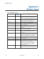
Appendix C
Module Types................................................................................................... 141
Appendix D
Vpd Data Files.................................................................................................. 143
D.1 EDK II Build System Output File Format ...................................................................... 143
D.2 Vpd Info File Format..................................................................................................... 145
x
December 2014
Version 1.24
EDK II DSC File Spec.
Tables
Table 1. EDK Build Infrastructure Support Matrix ........................................................................ 1
Table 2.Well-known Macro Statements ..................................................................................... 17
Table 3.Using System Environment Variable ............................................................................ 18
Table 4.Well-known Macro Statements ..................................................................................... 21
Table 5.Operator Precedence and Supported Operands .......................................................... 24
Table 6.EDK II [Defines] Section Elements ............................................................................... 27
Table 7.EDK II [BuildOptions] Section Elements: Optional Tags............................................... 30
Table 8.EDK II [BuildOptions] Variable Descriptions ................................................................ 31
Table 9.Standard Variables ..................................................................................................... 114
Table 10. EDK II Module Types ............................................................................................... 141
Version 1.24
December 2014
xi
EDK II DSC File Spec.
xii
December 2014
Version 1.24
EDK II DSC File Spec.
Figures
Figure 1. EDK II Parsing Data Flow ................................................................................. 10
Figure 2. Developer Workstation Layout - EDK II Build ................................................... 11
Version 1.24
December 2014
xiii
EDK II DSC File Spec.
xiv
December 2014
Version 1.24
EDK II DSC File Spec.
1
Introduction
1.1 Overview
This document describes the EDK II Platform Description file (DSC) format. The EDK
Build Tools are included as part of the EDK II compatibility package. In order to use
EDK II Modules or the EDK II Build Tools, an EDK II DSC and FDF file must be used.
EDK II tools use INI style text based files to describe components, platforms and
firmware volumes. While similar to EDK DSC files, the EDK II DSC file format is
different, and new utilities have been provided to process these files.
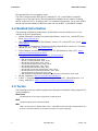
The EDK II Build Infrastructure supports creation of binary images that comply with
Unified EFI (UEFI) 2.4 and UEFI Platform Infrastructure (PI) 1.3 specifications.
This design has the following goals.
Compatible
The EDK II DSC format does not support EDK DSC format, nor can EDK tools be used to
parse the EDK II DSC format files. The EDK II DSC Format must maintain backward
compatibility for supporting existing EDK INF file formats. This means that the changes
made to this specification do not require changes for standard INF files.
Simplified platform build and configuration
One goal of this format is to simplify the build setup and configuration for a given platform.
It was also designed to simplify the process of adding EDK II firmware components to a
firmware volume on a given platform.
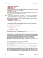
Table 1 describes the compatibility between platform, module and component builds.
Table 1. EDK Build Infrastructure Support Matrix
EDK
DSC
EDK II
DSC
EDK
FDF
EDK II
FDF
EDK
INF
EDK II
INF
EDK Build Tools
YES
NO
YES
NO
YES
NO
EDK II Build Tools
NO
YES
NO
YES
YES
YES
Note: This document is intended for persons doing EFI development and support for different platforms.
It is most likely only of interest in the event that there is a problem with a build, or if a developer
needs to perform special customizations of a build for a platform. This document is most likely only
of interest in the event that there is a problem with a build, or if a developer needs to perform
special customizations of a build for a platform.
The EDK II build processes, defined in the EDK II Build Specification, use separate steps
to create EFI images. The EDK II DSC file is used in conjunction with EDK II Flash
Description files (FDF), EDK II DEC, EDK II module INF and EDK component INF files to
generate binary PE32/PE32+/Coff files. The EDK II Makefiles, generated by the EDK II
parsing tool, contain only enough instructions to build the PE32/PE32+/Coff image files.
These makefiles do not contain information on the EFI format for FFS or FV file creation.
The Makefiles will support third party compilation tools – Microsoft, Intel and GCC tool
chains – and at least one EDK II tool, GenFw. The GenFw tool is used to manipulate the
Version 1.24
December 2014
1
Introduction
EDK II DSC File Spec.
files emitted from the compilation tools.
The EDK II build provides UEFI and PI (Unified EFI, Inc.) specification-compliant
images. Use of the tools in the EDK Compatibility package can be used for creating
earlier versions of EFI 1.10 and/or UEFI 2.0 compliant components. To be clear, EDK II
tools do not have the limitation of ECP tools, which can only do EFI 1.10 and UEFI 2.0 images.
1.2 Related Information
The following publications and sources of information may be useful to you or are
referred to by this specification:
•
Unified Extensible Firmware Interface Specification, Version 2.4, Unified EFI, Inc.,
2014, http://www.uefi.org.
•
UEFI Platform Initialization Specification, Version 1.3, Unified EFI, Inc., 2013, http:/
/www.uefi.org.
•
UEFI Platform Initialization Distribution Package Specification, Version 1.0 Errata B,
Unified EFI, Inc., 2014, http://www.uefi.org.
•
Intel® Platform Innovation Framework for EFI Specifications, Intel, 2007, http://
www.intel.com/technology/framework/.
•
http://tianocore.sourceforge.net/wiki/EDK_II_Specifications
— EDK II Module Writers Guide, Intel, 2010.
— EDK II User Manual, Intel, 2010.
— EDK II C Coding Standard, Intel, 2014.
— EDK II DEC Specification, Intel, 2014.
— EDK II INF File Specification, Intel, 2014.
— EDK II FDF Specification, Intel, 2014.
— EDK II Build Specification, Intel, 2014.
— EDK II UNI Unicode File Specification, Intel, 2014.
— EDK II Expression Syntax Specification, Intel, 2014.
— VFR Programming Language, Intel, 2012.
— EDK II Platform Configuration Database Infrastructure Description, Intel, 2009.
INI file, Wikipedia, http://en.wikipedia.org/wiki/INI_file.
•
•
C Now - C Programming Information, Langston University, Tulsa Oklahoma, J.H.
Young, 1999-2011, http://c.comsci.us/syntax/expression/ebnf.html.
1.3 Terms
The following terms are used throughout this document to describe varying aspects of
input localization:
BaseTools
The BaseTools are the tools required for an EDK II build.
BDS
Framework Boot Device Selection phase.
BNF
BNF is an acronym for “Backus Naur Form.” John Backus and Peter Naur introduced for the
first time a formal notation to describe the syntax of a given language.
2
December 2014
Version 1.24
EDK II DSC File Spec.
Introduction
Component
An executable image. Components defined in this specification support one of the defined
module types.
DEC
EDK II Package Declaration File. This file declares information about what is provided in the
package. An EDK II package is a collection of like content.
DEPEX
Module dependency expressions that describe runtime process restrictions.
Dist
This refers to a distribution package that conforms to the UEFI Platform Initialization
Distribution Package Specification.
DSC
EDK II Platform Description File. This file describes what and how modules, libraries and
components are to be built, as well as defining library instances which will be used when
linking EDK II modules.
DXE
Framework Driver Execution Environment phase.
DXE SAL
A special class of DXE module that produces SAL Runtime Services. DXE SAL modules differ
from DXE Runtime modules in that the DXE Runtime modules support Virtual mode OS calls
at OS runtime and DXE SAL modules support intermixing Virtual or Physical mode OS calls.
DXE SMM
A special class of DXE module that is loaded into the System Management Mode memory.
DXE Runtime
Special class of DXE module that provides Runtime Services
EBNF
Extended “Backus-Naur Form” meta-syntax notation with the following additional
constructs: square brackets “[…]” surround optional items, suffix “*” for a sequence of zero
or more of an item, suffix “+” for one or more of an item, suffix “?” for zero or one of an
item, curly braces “{…}” enclosing a list of alternatives and super/subscripts indicating
between n and m occurrences.
EDK
Extensible Firmware Interface Development Kit, the original implementation of the Intel®
Platform Innovation Framework for EFI Specifications developed in 2007.
EDK II
EFI Development Kit, version II that provides updated firmware module layouts and custom
tools, superseding the original EDK.
EDK Compatibility Package (ECP)
The EDK Compatibility Package (ECP) provides libraries that will permit using most existing
EDK drivers with the EDK II build environment and EDK II platforms.
EFI
Generic term that refers to one of the versions of the EFI specification: EFI 1.02, EFI 1.10
or any of the UEFI specifications.
Version 1.24
December 2014
3
Introduction
EDK II DSC File Spec.
FDF
EDK II Flash definition file. This file is used to define the content and binary image layouts
for firmware images, update capsules and PCI option ROMs.
FLASH
This term is used throughout this document to describe one of the following:
•
•
•
•
•
An image that is loaded into a hardware device on a platform - traditional ROM
image
An image that is loaded into an Option ROM device on an add-in card
A boot able image that is installed on removable, boot able media, such as a
Floppy, CD-ROM or USB storage device.
An image that is contains update information that will be processed by OS
Runtime services to interact with EFI Runtime services to update a traditional
ROM image.
A UEFI application that can be accessed during boot (at an EFI Shell Prompt),
prior to hand-off to the OS Loader.
Foundation
The set of code and interfaces that glue implementations of EFI together.
Framework
Intel® Platform Innovation Framework for EFI consists of the Foundation, plus other
modular components that characterize the portability surface for modular components
designed to work on any implementation of the Tiano architecture.
GUID
Globally Unique Identifier. A 128-bit value used to name entities uniquely. A unique GUID
can be generated by an individual without the help of a centralized authority. This allows
the generation of names that will never conflict, even among multiple, unrelated parties.
GUID values can be registry format (8-4-4-4-12) or C data structure format.
GUID also refers to an API named by a GUID.
HII
Human Interface Infrastructure. This generally refers to the database that contains string,
font, and IFR information along with other pieces that use one of the database components.
HOB
Hand-off blocks are key architectural mechanisms that are used to hand off system
information in the early pre-boot stages.
IFR
Internal Forms Representation. This is the binary encoding that is used for the
representation of user interface pages.
INF
EDK II Module Information File. This file describes how the module is coded. For EDK, this
file describes how the component or library is coded as well as providing some basic build
information.
Library Class
A library class defines the API or interface set for a library. The consumer of the library is
coded to the library class definition. Library classes are defined via a library class .h file that
is published by a package.
Library Instance
A module implementation of one or more library classes.
4
December 2014
Version 1.24
EDK II DSC File Spec.
Introduction
Module
A module is either an executable image or a library instance. For a list of module types
supported by this package, see module type.
Module Type
All libraries and components belong to one of the following module types: BASE, SEC,
PEI_CORE, PEIM, DXE_CORE, DXE_DRIVER, DXE_RUNTIME_DRIVER, DXE_SMM_DRIVER,
DXE_SAL_DRIVER, UEFI_DRIVER, or UEFI_APPLICATION. These definitions provide a
framework that is consistent with a similar set of requirements. A module that is of module
type BASE, depends only on headers and libraries provided in the MDE, while a module that
is of module type DXE_DRIVER depends on common DXE components. The EDK II build
system also permits modules of type USER_DEFINED. These modules will not be processed
by the EDK II Build system. For a definition of the various module types, see Appendix C.
Package
A package is a container. It can hold a collection of files for any given set of modules.
Packages may be described as one of the following types of modules:
— source modules, containing all source files and descriptions of a module
— binary modules, containing EFI Sections or a Framework File System and a description
file specific to linking and binary editing of features and attributes specified in a Platform
Configuration Database (PCD,)
— mixed modules, with both binary and source modules
Multiple modules can be combined into a package, and multiple packages can be combined
into a single package.
PCD
Platform Configuration Database.
PEI
Pre-EFI Initialization Phase.
PEIM
An API named by a GUID.
PPI
A PEIM-to-PEIM Interface that is named by a GUID.
Protocol
An API named by a GUID.
Runtime Services
Interfaces that provide access to underlying platform-specific hardware that might be
useful during OS runtime, such as time and date services. These services become active
during the boot process but also persist after the OS loader terminates boot services.
SAL
System Abstraction Layer. A firmware interface specification used on Intel® Itanium®
Processor based systems.
SEC
Security Phase is the code in the Framework that contains the processor reset vector and
launches PEI. This phase is separate from PEI because some security schemes require
ownership of the reset vector.
SKU
Stock Keeping Unit.
Version 1.24
December 2014
5
Introduction
EDK II DSC File Spec.
SMM
System Management Mode. A generic term for the execution mode entered when a CPU
detects an SMI. The firmware, in response to the interrupt type, will gain control in physical
mode. For this document, "SMM" describes the operational regime for IA32 and x64
processors that share the OS-transparent characteristics.
UEFI Application
An application that follows the UEFI specification. The only difference between a UEFI
application and a UEFI driver is that an application is unloaded from memory when it exits
regardless of return status, while a driver that returns a successful return status is not
unloaded when its entry point exits.
UEFI Driver
A driver that follows the UEFI specification.
UEFI Specification Version 2.4
Current UEFI version.
UEFI Platform Initialization Distribution Package Specification Version 1.0
The current version of the specification includes Errata B.
UEFI Platform Initialization Specification 1.3
Current version of the PI specification.
Unified EFI Forum
A non-profit collaborative trade organization formed to promote and manage the UEFI
standard. For more information, see www.uefi.org.
VFR
Visual Forms Representation.
VPD
Vital Product Data that is read-only binary configuration data, typically located within a
region of a flash part. This data would typically be updated as part of the firmware build,
post firmware build (via patching tools), through automation on a manufacturing line as the
'FLASH' parts are programmed or through special tools.
1.4 Conventions Used in this Document
This document uses typographic and illustrative conventions described below.
1.4.1 Data Structure Descriptions
Intel® processors based on 32 bit Intel® architecture (IA 32) are "little endian"
machines. This distinction means that the low-order byte of a multi byte data item in
memory is at the lowest address, while the high-order byte is at the highest address.
Processors of the Intel® Itanium® processor family may be configured for both "little
endian" and "big endian" operation. All implementations designed to conform to this
specification will use "little endian" operation.
In some memory layout descriptions, certain fields are marked reserved. Software
must initialize such fields to zero and ignore them when read. On an update operation,
software must preserve any reserved field.
The data structures described in this document generally have the following format:
6
December 2014
Version 1.24
EDK II DSC File Spec.
Introduction
Summary:
A brief description of the data structure.
Prototype:
An EBNF-type declaration for the data structure.
Example:
Sample data structure using the prototype.
1.4.2 Pseudo-Code Conventions
Pseudo code is presented to describe algorithms in a more concise form. None of the
algorithms in this document are intended to be compiled directly. The code is presented
at a level corresponding to the surrounding text.
In describing variables, a list is an unordered collection of homogeneous objects. A
queue is an ordered list of homogeneous objects. Unless otherwise noted, the ordering
is assumed to be FIFO.
Pseudo code is presented in a C-like format, using C conventions where appropriate.
The coding style, particularly the indentation style, is used for readability and does not
necessarily comply with an implementation of the UEFI Specification.
1.4.3 Typographic Conventions
This document uses the typographic and illustrative conventions described below:
Typographic
Convention
Typographic convention description
Plain text
The normal text typeface is used for the vast majority of the descriptive text in a
specification.
Plain text (blue)
Any plain text that is underlined and in blue indicates an active link to the crossreference. Click on the word to follow the hyperlink.
Bold
In text, a Bold typeface identifies a processor register name. In other instances, a
Bold typeface can be used as a running head within a paragraph.
Italic
In text, an Italic typeface can be used as emphasis to introduce a new term or to
indicate a manual or specification name.
BOLD Monospace
Computer code, example code segments, and all prototype code segments use a
BOLD Monospace typeface with a dark red color. These code listings normally
appear in one or more separate paragraphs, though words or segments can also be
embedded in a normal text paragraph.
Bold Monospace
Words in a Bold Monospace typeface that is underlined and in blue indicate
an active hyper link to the code definition for that function or type definition. Click on
the word to follow the hyper link.
$(VAR)
This symbol VAR defined by the utility or input files.
Italic Monospace
In code or in text, words in Italic Monospace indicate placeholder names
for variable information that must be supplied (i.e., arguments).
Version 1.24
December 2014
7
Introduction
EDK II DSC File Spec.
Note: Due to management and file size considerations, only the first occurrence of the reference on
each page is an active link. Subsequent references on the same page will not be actively linked to
the definition and will use the standard, non underlined BOLD Monospace typeface. Find the first
instance of the name (in the underlined BOLD Monospace typeface) on the page and click on
the word to jump to the function or type definition.
The following typographic conventions are used in this document to illustrate the
Extended Backus-Naur Form.
[item]
Square brackets denote the enclosed item is optional.
{item}
Curly braces denote a choice or selection item, only one of which may
occur on a given line.
<item>
Angle brackets denote a name for an item.
(range-range)
Parenthesis with characters and dash characters denote ranges of
values, for example, (a-zA-Z0-9) indicates a single alphanumeric
character, while (0-9) indicates a single digit.
“item”
Characters within quotation marks are the exact content of an item, as
they must appear in the output text file.
?
The question mark denotes zero or one occurrences of an item.
*
The star character denotes zero or more occurrences of an item.
+
The plus character denotes one or more occurrences of an item.
item{n}
A superscript number, n, is the number occurrences of the item that must
be used. Example: (0-9)8 indicates that there must be exactly eight digits,
so 01234567 is valid, while 1234567 is not valid.
8
item{n,}
A superscript number, n, within curly braces followed by a comma “,”
indicates the minimum number of occurrences of the item, with no
maximum number of occurrences.
item{,n}
A superscript number, n, within curly brackets, preceded by a comma
“,”indicates a maximum number of occurrences of the item.
item{n,m}
A super script number, n, followed by a comma “,“ and a number, m,
indicates that the number of occurrences can be from n to m occurrences
of the item, inclusive.
December 2014
Version 1.24
EDK II DSC File Spec.
2
DSC Overview
This section of the document provides an overview to processing EDK II platform
description (DSC) file. Additional chapters describe different sections of the EDK II DSC
file in detail.
EDK II parsing tools contain the templates for processing files to create the component
binary images from source files. Binary Modules are not included in EDK II DSC files.
EDK II DSC files are a list of:
•
EDK Component or EDK II Module INF Files
•
EDK libraries (only used by EDK Components)
•
EDK II Library Class Instance Mappings (only used by EDK II Modules)
•
EDK II PCD Entries
Note: Path and Filename elements within the DSC are case-sensitive in order to support building on
UNIX style operating systems.
Note: This document uses “\” to indicate that a line that cannot be displayed in this document on a single
line. Within the DSC specification, each entry must appear on a single line.
Note: The the total path and file name length is limited by the operating system and third party tools. It is
recommended that for EDK II builds that the WORKSPACE directory be either a directory under a
subst drive in Windows (s:/build as an example) or be located in either the /opt directory or in the
user’s /home/username directory for Linux and OS/X.
2.1 Processing Overview
Each platform DSC file is broken out into sections in a manner similar to the component
description (INF) files. However, while the intent of a component’s INF file is to define
the source files, libraries (or library classes), and definitions relevant to building the
component, the function of the platform DSC file is to specify the library instances,
components and output formats used to generate binary files that will be processed by
other tools to generate an image that is either put into a flash device, made available
for recovery booting or updating existing firmware on a platform.
Note: For users familiar with EDK, the EDK II DSC file is not used to specify how compiled binary images
get placed into UEFI/PI compliant binaries. The EDK II Flash Description File (FDF) file specifies
how to package the binaries files into UEFI/PI compliant images.
In general, the parsing utilities read each line from the sections of the platform
description (DSC) file, process the component, module, or library’s INF file on the line
to generate a makefile, and then continue with the next line.
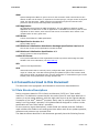
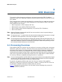
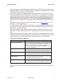
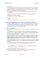
Figure 1 illustrates the process flow, with the dark format indicating the process for
building PE/PE32+/Coff files.
Version 1.24
December 2014
9
DSC Overview
EDK II DSC File Spec.
Figure 1. EDK II Parsing Data Flow
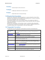
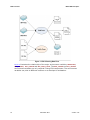
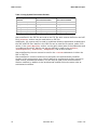
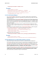
Figure 2 illustrates the relationship of the major environment variables, WORKSPACE,
EDK_SOURCE, EFI_SOURCE and EDK_TOOLS_PATH. The EDK_SOURCE and EFI_SOURCE
environment variables are only required if using EDK components. The environment
variables can point to different locations on a developer’s workstation.
10
December 2014
Version 1.24
EDK II DSC File Spec.
DSC Overview
Figure 2. Developer Workstation Layout - EDK II Build
2.2 Build Description File Format
EDK II build description files--DSC, FDF, DEC and INF files, along with other files like
build_rules.txt, target.txt and tools_def.txt, contain information used by the parsing utility to
create makefiles that process source files to generate binary (PE32/PE32+/Coff) files.
The binary files can be distributed as EDK II binary packages or used to create a
platform are defined in an FDF file, rather than the EDK II DSC file.
2.2.1 Section Entries
To simplify parsing, the EDK II meta-data files continue using the INI format. This style
was introduced for EDK meta-data files, when only the Windows tool chains were
supported. It was decided that for compatibility purposes, that INI format would
continue to be used. EDK II formats differ from the de facto INI format in that the semicolon “;” character cannot be used to indicate a comment.
Leading and trailing space/tab characters must be ignored.
Version 1.24
December 2014
11
DSC Overview
EDK II DSC File Spec.
Duplicate section names must be merged by tools.
This description file consists of sections delineated by section tags enclosed within
square [] brackets. Section tag entries are case-insensitive. The different sections and
their usage are described below. The text of a given section can be used for multiple
section names by separating the section names with a comma. For example:
[LibraryClasses.X64, LibraryClasses.ipf]
The content below each section heading is processed by the parsing utilities in the order
that they occur in the file. The precedence for processing these architecture section
tags is from right to left, with sections defining an architecture having a higher
precedence than a section which uses common (or no architecture extension) as the
architecture.
Note: Content, such as filenames, directory names, macros and C variable names, within a section IS
case sensitive. IA32, Ia32 and ia32 within a section are processed as separate items. (Refer to
Naming Conventions below for more information on directory and/or file naming.)
Sections are terminated by the start of another section or the end of the file.
Comments are not permitted between square brackets of a section specifier.
Duplicate sections (two sections with identical section tags) will be merged by tools,
with the second section appended to the first.
If architectural modifiers are used in the section tag, the section is merged by tools with
content from common sections (if specified) with the architectural section appended to
the first, into an architectural section. For example, given the following:
[BuildOptions]
MSFT:*_*_*_CC_FLAGS = /nologo
[BuildOptions.IA32]
MSFT:*_*_IA32_CC_FLAGS = /D MDEPKG_NDEBUG
[BuildOptions.X64]
MSFT:*_*_X64_CC_FLAGS = /Gy
After the first pass of the tools, when building the module for IA32, the source files will
logically be:
[BuildOptions.IA32]
MSFT:*_*_*_CC_FLAGS = /nologo
MSFT:*_*_IA32_CC_FLAGS = /D MDEPKG_NDEBUG
When building the module for X64, the source files will logically be:
[BuildOptions.X64]
MSFT:*_*_*_CC_FLAGS = /nologo
MSFT:*_*_X64_CC_FLAGS = /Gy
The [Defines] section tag prohibits use of architectural modifiers. All other sections
can specify architectural modifiers.
2.2.2 Comments
The hash "#" character indicates comments in the Platform Description (DSC) file. In
line comments terminate the processing of a line. In line comments must be placed at
the end of the line, and may not be placed within the section ([,]) tags.
Only FIX_LOAD_TOP_MEMORY_ADDRESS = 0xF0000000 in the following example is
processed by tools; the remainder of the line is ignored:
12
December 2014
Version 1.24
EDK II DSC File Spec.
FIX_LOAD_TOP_MEMORY_ADDRESS
DSC Overview
= 0xF0000000
# set top memory address
Note: Blank lines and lines that start with the hash "#" character must be ignored by tools.
Hash characters appearing within a quoted string are permitted, with the string being
processed as a single entity. The following example must handle the quoted string as
single element by tools.
UI = "# Copyright 2007, NoSuch, ltd. All rights reserved."
2.2.3 Valid Entries
Processing of the line is terminated if a comment is encountered.
Processing of a line is terminated by the end of the line.
Items in quotation marks are treated as a single token and have the highest
precedence. Items encapsulated in parenthesis are also treated as tokens, with
embedded tokens being processed first. All other processing occurs from left to right.
In the following example, B - C is processed first, then result is added to A followed by
adding 2; finally 3 is added to the result.
(A + (B - C) + 2) + 3
In the next example, A + B is processed first, then C + D is processed and finally the
two results are added.
(A + B) + (C + D)
Space and tab characters are permitted around field separators.
2.2.4 Naming Conventions
The EDK II build infrastructure is supported under Microsoft* Windows*, Linux* and
MAC OS/X operating systems. All directory and file names must be treated as case
sensitive because of multiple environment support.
•
The use of special characters in directory names and file names is restricted to the
dash, underscore, and period characters, respectively "-", "_", and ".".
•
Period characters may not be followed by another period character. File and
Directory names must not start with “./”, “.” or “..”.
•
Directory names and file names must not contain space characters.
•
Directory Names must only contain alphanumeric characters, the dash and
underscore characters and start with an alpha character. A single period character is
permitted in the name provided that alphanumeric characters appear before and
after the period character (as in: MdePkg.1).
•
Additionally, all EDK II directories that are architecturally dependent must use a
name with only the first character capitalized. Ia32, Ipf, X64 and Ebc are valid
architectural directory names. IA32, IPF and EBC are not acceptable directory
names, and may cause build breaks. From a build tools perspective, IA32 is not
equivalent to Ia32 or ia32.
The build tools must be able to process the tool definitions file: tools_def.txt (describing
the location and flags for compiler and user defined tools), which may contain space
characters in paths on Windows* systems.
Version 1.24
December 2014
13
DSC Overview
EDK II DSC File Spec.
Note: The tools_def.txt file and [BuildOptions] sections are the places that permit the use of space
characters in a directory path.
The EDK II Coding Style specification covers naming conventions for use within C Code
files, and as well as specifying the rules for directory and file names. This section is
meant to highlight those rules as they apply to the content of the INF files.
Architecture keywords (IA32, IPF, X64 and EBC) are used by build tools and in metadata files for describing alternate threads for processing of files. These keywords must
not be used for describing directory paths. Additionally, directory names with
architectural names (Ia32, Ipf, X64 and Ebc) do not automatically cause the build tools
or meta-data files to follow these alternate paths. Directories and Architectural
Keywords are similar in name only.
All directory paths within EDK II INF files must use the "/" forward slash character to
separate directories as well as directories from filenames. Example:
C:/Work/Edk2/edksetup.bat
File names must also follow the same naming convention required for directories. No
space characters are permitted. The special characters permitted in directory names
are the only special characters permitted in file names.
2.2.5 !include Statement Processing
The !include statement may appear within any section of EDK II DSC file. The
included file content must match the content type of the current section definition,
contain complete sections, or combination of both.
The argument of this statement is a filename. The file is relative to the directory that
contains this DSC file, and if not found the tool must attempt to find the file relative to
the $(WORKSPACE) directory. The use of the system environment variables,
$(WORKSPACE), $(EFI_SOURCE), $(EDK_SOURCE), $(ECP_SOURCE) in the file name is
permitted. If the file is still not found, the parsing tools must terminate with an error.
Files specified by !include statements may not contain !include statements.
Statements in !include files must not break the integrity of the DSC file, the included
file is read in by tools in the exact position of the file, and is functionally equivalent of
copying the contents of the included file and inserting (paste) the content into the DSC
file.
Macros, defined in this file, are not permitted in the path or file name of the !include
statement, as these files are included prior to processing the file for macros. If the path
starts with a “$” character, then one of the system environment variables,
$(WORKSPACE), $(EDK_SOURCE), $(EFI_SOURCE), or $(ECP_SOURCE) is being used; only
these system environment variables are permitted to start the path of the included file.
The following examples show the valid usage of the !include statement.
14
December 2014
Version 1.24
EDK II DSC File Spec.
DSC Overview
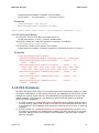
[LibraryClasses]
BaseLib|MdePkg/Library/BaseLib/BaseLib.inf
!include MyPlatformCommonLibs.txt
[LibraryClasses]
DEFINE MDELIBUAEP = MdePkg/Library/UefiApplicationEntryPoint
UefiApplicationEntryPoint|$(MDELIBUAEP)/UefiApplicationEntryPoint.inf
!include Sample.txt
### Contents of Sample.txt
DEFINE EMULATE = 1
!if $(EMULATE) == 0
[LibraryClasses.IA32]
TimerLib|Some/Existing/TimerLib/Instance.inf
[LibraryClasses.X64]
TimerLib|Another/Existing/TimerLib/Instance.inf
!else
TimerLib|The/NULL/TimerLib/Instance.inf
!endif
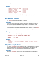
2.2.6 Macro Statements
The use of MACRO statements, which assign a value to a variable. Macros defined in the
[Defines] section are considered global during the processing of the DSC file and the
FDF file. This means that a Macro can be used in the FDF file without defining it in the
FDF as long as it is defined in the DSC file.
Token names (words defined in the EDK II meta-data file specifications) cannot be used
as macro names. As an example, using PLATFORM_NAME as a macro name is not
permitted, as it is a token defined in the DSC file’s [Defines] section.
Macros in the DSC file can be used to specify paths (and paths and filenames), and
build options. They can define other items, such as values for PCDs, expressions or
names that can be used in conditional directive statements, which allows customization
of the build, allowing the platform integrator to select features from the command-line.
The format for the macro statements is:
DEFINE MACRO = Path
Any portion on a path or path and filename can be defined by a macro.
When assigning a string value to a macro, the string must follow the C format for
specifying a string, as shown below:
DEFINE MACRO1 = "SETUP"
DEFINE MACRO2 = L"SETUP"
When assigning a numeric value to a macro, the number may be a decimal, integer or
hex value, as shown below:
Version 1.24
December 2014
15
DSC Overview
EDK II DSC File Spec.
DEFINE MACRO1 = 0xFFFFFFFF
DEFINE MACRO2 = 2.3
DEFINE MACRO3 = 10
The format for usage of a Macro varies. When used as a value, the Macro name must be
encapsulated by “$(“ and “)” as shown below:
$(MACRO)/filename.foo
When a macro is tested in a conditional directive statement, determining whether it has
been define or undefined uses the following format:
!ifdef MACRO
Note: For backward compatibility, tools may allow $(MACRO) in the !ifdef and !ifndef statements.
This functionality may disappear in future releases, therefore, it is recommended that platform
integrators update their DSC files if they also alter other content.
When using string comparisons of Macro elements to string literals, the format of the
conditional directive must be:
!if $(MACRO) == "Literal String"
Note: For backward compatibility, tools may allow testing literal strings that are not encapsulated by
double quotation marks. This functionality may disappear in future releases, therefore, it is
recommended that platform integrators update their DSC files if they also alter other content.
When testing Macro against another Macro:
!if $(MACROALPHA) == $(MACROBETA)
When testing a Macro against a value:
!if $(MACRONUM) == 2
or
!if $(MACROBOOL) == TRUE
When used with the !if or !elseif statements or in an expression used in a value
field, a macro that has not been defined has a value of 0.
Any defined MACRO definitions will be expanded by tools when they encounter the
entry in the section except when the macro is within double quotation marks in build
options sections. The expectation is that macros in the quoted values will be expanded
by external build scripting tools, such as nmake or gmake; they will not be expanded by
the build tools. If a macro that is not defined is used in locations that are not
expressions (where the tools would just do macro expansion as in C flags in a
[BuildOptions] section), nothing will be emitted. If the macro, MACRO1, has not been
defined, then:
MSFT:*_*_*_CC_FLAGS = /c /nologo $(MACRO1) /Od
After macro expansion, the logical result would be equal to:
MSFT:*_*_*_CC_FLAGS = /c /nologo /Od
It is recommended that tools remove any excess space characters when processing
these types of lines.
Macro evaluation is done at the time the macro is used in an expression, conditional
directive or value field, not when a macro is defined. Macros in quoted strings will not
be expanded by parsing tools; all other macro values will be expanded, without
evaluation, as other elements of the build system will perform any needed tests. Macro
Definition statements that appear within a section of the file (other than the [Defines]
section) are scoped to the section they are defined in. If the Macro statement is within
the [Defines] section, then the Macro is considered global to the entire DSC file, files
16
December 2014
Version 1.24
EDK II DSC File Spec.
DSC Overview
included using the !include statement and global to the FDF file, with local definitions
taking precedence (if the same MACRO name is redefined in subsequent sections, then
that MACRO value is local to only that section.)
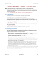
Macros may be used in conditional statements located within the DSC (and FDF) file.
Conditional MACROs may be defined on a command line of a parsing tool. It is highly
recommended that a macro defined in this manner have a DEFINE statement to set a
default value in the [Defines] section. (Macro values specified on the command-line
override all definitions of that Macro.) In the reference build (Nt32Pkg/Nt32Pkg.dsc),
macros set on a command line override any macro value defined in the DSC (or FDF)
file.
MACROs may also be used as values in PCD statements. See Section 3.10 for more
information on PCD statements.
In order to support EDK components and libraries, the word DEFINE is replaced with
EDK_GLOBAL. The EDK_GLOBAL macros are considered global during the processing of
the DSC, FDF and EDK INF files.
Macros that appear within double quotation marks in build options sections are not
expanded. It is assumed that they will be expanded by the OS or external scripting
tools.
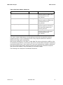
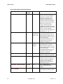
Global variables that may be used in EDK II DSC and FDF meta-data files are listed in
the Well-known Macro Statements table, while the format of the System Environment
variables that may be used in EDK II DSC and FDF files are in the next table.
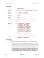
Table 2. Well-known Macro Statements
Exact Notation
Derivation
$(OUTPUT_DIRECTORY)
Used in FDF [FV] and [Capsule] sections; the value
comes from parsing either the DSC file or via a command line
option. This is commonly the Build/Platform name directory
created by the build system in the EDK II WORKSPACE,
however, it is possible to specify the output directory outside
of the EDK II WORKSPACE.
$(TARGET)
Used in various locations; valid values are derived from INF,
DSC, target.txt, tool options and tools_def.txt. FDF parsing
tools may obtain these values from command-line options.
$(TOOL_CHAIN_TAG)
Used in various locations; valid values are derived from INF,
DSC, target.txt, tool options and tools_def.txt. FDF parsing
tools may obtain these values from command-line options.
$(TOOLCHAIN)
A synonym for $(TOOL_CHAIN_TAG), with the value derived
from INF, DSC, target.txt and tools_def.txt.
This item has been deprecated, and must not be used.
$(ARCH)
Used in various locations, valid values are derived from INF,
DSC, target.txt, tool options and tools_def.txt. FDF parsing
tools may obtain these values from command-line options.
System environment variables may be referenced, however their values must not be
altered.
Version 1.24
December 2014
17
DSC Overview
EDK II DSC File Spec.
Table 3. Using System Environment Variable
Macro Style Used in MetaData files
Matches Windows
Environment Variable
Matches Linux & OS/X
Environment Variable
$(WORKSPACE)
%WORKSPACE%
$WORKSPACE
$(EFI_SOURCE)
%EFI_SOURCE%
$EFI_SOURCE
$(EDK_SOURCE)
%EDK_SOURCE%
$EDK_SOURCE
$(ECP_SOURCE)
%ECP_SOURCE%
$ECP_SOURCE
$(EDK_TOOLS_PATH)
%EDK_TOOLS_PATH%
$EDK_TOOLS_PATH
Macros defined in the FDF file are local to the FDF file while macros defined in the DSC
file’s [Defines] section may be used within an FDF file.
Additionally, the macros may be used in conditional directive statements located within
the DSC and FDF files. Macros in the DSC file can be used for file names, paths, PCD
values, in the [BuildOptions] section, on the right (value) side of the statements and
in conditional directives. Macros can also be defined or used in the [Defines],
[LibraryClasses], [Libraries], [Components] and all PCD sections.
Macros defined by the user cannot be used in the !include statements in either the
DSC or FDF file.
Macros defined in common sections may be used in the architecturally modified
sections of the same section type. Macros defined in architectural sections cannot be
used in other architectural sections, nor can they be used in the common section.
Section modifiers in addition to the architectural modifier follow the same rules as
architectural modifiers.
18
December 2014
Version 1.24
EDK II DSC File Spec.
DSC Overview
Example
[LibraryClasses.common]
DEFINE MDE = MdePkg/Library
BaseLib|$(MDE)/BaseLib.inf
[LibraryClasses.X64, LibraryClasses.IA32]
# Can use $(MDE), cannot use $(MDEMEM)
DEFINE PERF = PerformancePkg/Library
TimerLib|$(PERF)/DxeTscTimerLib/DxeTscTimerLib.inf
[LibraryClasses.X64.PEIM]
# Can use $(MDE) and $(PERF)
DEFINE MDEMEM = $(MDE)/PeiMemoryAllocationLib
MemoryAllocationLib|$(MDEMEM)/PeiMemoryAllocationLib.inf
[LibraryClasses.IPF]
# Cannot use $(PERF) or $(MDEMEM)
# Can use $(MDE) from the common section
PalLib|$(MDE)/UefiPalLib/UefiPalLib.inf
TimerLib|$(MDE)/BaseTimerLibNullTemplate/BaseTimerLibNullTemplate.inf
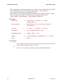
2.2.7 EDK_GLOBAL
The EDK_GLOBAL statements defined in the DSC file can be used during the processing
of the DSC, FDF and EDK INF files. The definition of the EDK_GLOBAL name must only be
done in the DSC [Defines] section. These special macros can be used in path
statements, DSC file [BuildOptions] and FDF file [Rule] sections. These statements
are used to replace the environment variables that were defined for the EDK build tools.
They must never be used in a conditional directive statement in the DSC and FDF files,
nor can they be used by EDK II INF files.
2.2.8 Conditional Directive Statements (!if...)
Conditional directive statements are used by the build tools preprocessor function to
include or exclude statements in the DSC file. A limited number of statements are
supported, and nesting of conditionals is also supported. Statements are prefixed by
the exclamation “!” character. Conditional statements may appear anywhere within the
DSC file.
Note: A limited number of statements are supported. This specification does not support every
conditional statement that C programmers are familiar with.
Supported statements are:
!ifdef, !ifndef, !if, !elseif, !else and !endif
Refer to the Macro Statement section for information on using Macros in conditional
directives.
When using the !ifdef or !ifndef, the macro name can be used; the macro name
must not be encapsulated between $( and ). It is the name of the macro that is used
for testing, not the value of the macro.
PCDs must not be used in the !ifdef or !ifndef statements.
Version 1.24
December 2014
19
DSC Overview
EDK II DSC File Spec.
Note: For backward compatibility, the EDK II build system will also process the !ifdef or !ifndef
statements with the macro encapsulated between $( and ).
When using a marco in the !if or !elseif conditionals, the macro name must be
encapsulated between $( and ).
A macro that is not defined has a default value of 0 (FALSE) when used in a conditional
comparison statement.
When using a PCD in the !if or !elseif conditionals, the PCD name
(TokenSpaceGuidCName.PcdCname) can be used; the PCD name must not be
encapsulated between $( and )nor between PCD( and ). Do not encapsulate the PCD
name in the “$(“ and “)” required for macro values as shown in the example below.
!if ( gTokenSpaceGuid.PcdCname == 1 ) AND ( $(MY_MACRO) == TRUE )
DEFINE FOO=TRUE
!endif
If the PCD is a string, only the string needs to be encapsulated by double quotation
marks, while a Unicode string can have the double quoted string prefixed by “L”, as in
the following example:
!if gTokenSpaceGuid.PcdCname == L"Setup"
DEFINE FOO=TRUE
!endif
If a PCD is used in a conditional statement, the value must first come from the FDF file,
then from the DSC file. If the value cannot be determined from these two locations, the
build system should break with an error message.
Note: PCDs, used in conditional directives, must be defined and the value set in either the FDF or DSC
file in order to be used in a conditional statement; values from INF or DEC files are not permitted.
When used in !if and !elseif conditional comparison statements, it is the value of the
Macro or the PCD that is used for testing, not the name of the macro or PCD.
Strings can only be compared to strings of a like type (testing an ASCII string against a
Unicode format string must fail), numbers can only be compared against numbers and
boolean objects can only evaluate to TRUE or FALSE. See the Operator Precedence
table, in the Expressions section below for a list of restrictions on comparisons.
Using macros in conditional directives that contain flags for use in the [BuildOptions]
sections is not recommended.
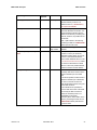
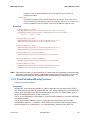
The following external macro names can be used in conditional directives without
defining them in DSC or FDF files.
20
December 2014
Version 1.24
EDK II DSC File Spec.
DSC Overview
Table 4. Well-known Macro Statements
Tag
Value
Notes
$(FAMILY)
Tool Chain Family
The value must be a string
comparison against a FAMILY value
that is defined in the Conf/
tools_def.txt file
$(TARGET)
Build Target
The value must be a string
comparison against a TARGET value
that is defined in the Conf/
tools_def.txt file
$(TOOL_CHAIN_TAG)
Tool Chain Name
The value must be a string
comparison against a tool chain tag
name value that is defined in the
Conf/tools_def.txt file.
$(ARCH)
Architecture
The value must be a string
comparison against an architecture
that is defined in the Conf/
tools_def.txt file.
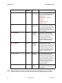
The macro values listed above are derived from the build command-line options
(highest priority) or the Conf/target.txt file. They may be combined in directive
statements using logical expressions.
Most section definitions in the EDK II meta-data files have architecture modifiers. Use
of architectural modifiers in the section tag is the recommended method for specifying
architectural differences. Some sections do not have architectural modifiers and there
are some unique cases where having a method for specifying architectural specific
items would be valuable, hence the ability to use these values.
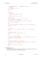
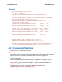
The following are examples of conditional directives.
Version 1.24
December 2014
21
DSC Overview
EDK II DSC File Spec.
!if ("MSFT" IN $(FAMILY)) or ("INTEL" IN $(FAMILY))
... statements
!elseif $(FAMILY) == "GCC"
... statements
!endif
!ifdef FOO
!ifndef BAR
# FOO defined, BAR not defined
!else
# FOO defined, BAR is defined
!endif
!elseif $(BARFOO)
# FOO is not defined, BARFOO evaluates to TRUE
!elseif $(BARFOO) == $(FOOBAR)
# FOO is not defined, BARFOO equals the value of FOOBAR
# (in this case, FALSE)
!else
# FOO is not defined while BARFOO evaluates to FALSE and FOOBAR
# evaluates to TRUE
!endif
!if $(FOO) == 2
# The numeric value of FOO was defined as 2, as in DEFINE FOO = 2
!endif
!if MyTspGUID.MyPcd == 2
# The value of PCD, MyTspGUID.MyPcd, is 2
!endif
!if $(FOO) == "MyPlatformName"
# This is a string comparison, where the MACRO FOO was set using:
# DEFINE FOO = "MyPlatformName"
!endif
!if MyTspGUID.MyTspGUID == "MyPlatform"
# This is a string comparison where PCD VOID* value is “MyPlatform”,
# and must be a null terminated string.
!else
# The strings do not match exactly
!endif
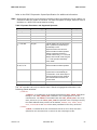
2.2.9 Expressions
Expressions can be used in conditional directive comparison statements and in value
fields for Macros and PCDs in the DSC and FDF files.
22
December 2014
Version 1.24
EDK II DSC File Spec.
DSC Overview
Refer to the EDK II Expression Syntax Specification for additional information.
Note: Note that the data types are not required to be literal numbers, but rather they can be a Macro or a
PCD whose value is a number or a boolean. The same rule applies for strings, where the value of
the Macro or a VOID* PCD can be tested as a string.
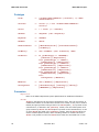
Table 5. Operator Precedence and Supported Operands
Operator
Use with Data Types
Notes
or, OR, ||
Number, Boolean
and, AND, &&
Number, Boolean
|
Number, Boolean
Bitwise OR
^, xor, XOR
Number, Boolean
Exclusive OR
&
Number, Boolean
Bitwise AND
==, !=, EQ, NE,
IN
All types
The IN operator can only be used to
test a quoted unary literal string for
membership in a list
Space characters must be used
before and after the letter operators
Strings compared to boolean or
numeric values using “==” or “EQ” will
always return FALSE, while using the
“!=” or “NE” operators will always
return TRUE
<=, >=, <, >,
LE, GE, LT, GT
All
Space characters must be used
before and after the letter operators.
+, -
Number, Boolean
Cannot be used with strings - the
system does not automatically do
concatenation. Tools should report a
warning message if these operators
are used with both a boolean and
number value
!, not, NOT
Number, Boolean
Priority
Lowest
Highest
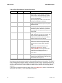
The "IN" operator can only be used to test a literal string against elements in the
following global variables:
$(FAMILY)
$(FAMILY) is considered a list of families that different TOOL_CHAIN_TAG values
belong to. The TOOL_CHAIN_TAG is defined in the Conf/target.txt or on the
command-line. The FAMILY is associated with the TOOL_CHAIN_TAG in the Conf/
tools_def.txt file (or the TOOLS_DEF_CONF file specified in the Conf/target.txt file)
file. While different family names can be defined, ARMGCC, GCC, INTEL, MSFT,
RVCT, RVCTCYGWIN and XCODE have been predefined in the tools_def.txt file.
$(ARCH)
$(ARCH) is considered the list of architectures that are to be built, that were
specified on the command line or come from the Conf/target.txt file.
Version 1.24
December 2014
23
DSC Overview
EDK II DSC File Spec.
$(TOOL_CHAIN_TAG)
$(TOOL_CHAIN_TAG) is considered the list of tool chain tag names specified on
the command line
$(TARGET)
$(TARGET) is considered the list of target (such as DEBUG, RELEASE and NOOPT)
names specified on the command line or come from the Conf/target.txt file.
For logical expressions, any non-zero value must be considered TRUE.
Invalid expressions must cause a build break with an appropriate error message.
2.2.10 Section Handling
The DSC file parsing routines must process the sections so that common architecture
sections are logically merged with the architecturally specific sections. The architectural
sections need to be processed so that they are logically after the common section. It is
recommended that EDK II developers use a logical ordering of the sections.
Other section modifiers must also be logically appended to the merged sections (for
DSC files that have architectural and common architecture sections) after the merge.
For [BuildOptions] sections in the DSC file, the entries with a common left side (of
the "=") will be either appended or replace previous entries based on the "==" replace or
"=" append assignment character sequence.
Common Section + Architectural Section + Common Section w/extra Modifier
+ Architectural Section w/extra Modifier
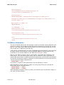
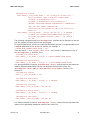
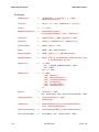
Example:
[BuildOptions.Common]
MSFT:*_*_*_CC_FLAGS = /nologo
[BuildOptions.Common.EDK]
MSFT:*_*_*_CC_FLAGS = /Od
[BuildOptions.IA32]
MSFT:*_*_IA32_CC_FLAGS = /D EFI32
For IA32 architecture builds of an EDK II INF file would logically be:
MSFT:*_*_IA32_CC_FLAGS = /nologo /D EFI32
For non-IA32 architecture EDK INF files, tool parsing would logically be:
MSFT:*_*_*_CC_FLAGS = /nologo /Od
For IA32 architecture builds of an EDK INF file, tool parsing would logically be:
MSFT:*_*_IA32_CC_FLAGS = /nologo /D EFI32 /Od
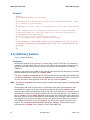
2.3 [Defines] Section Processing
The defines section of an EDK II DSC file is used to define variable assignments that
can be used in later build steps.
This section is required in all EDK II DSC files.
This section must be the first section in the file (following the header comments) in
order to simplify definition of macro statement processing. Ordering statements within
the section is not required, with the exception that a Macro must be defined before it is
24
December 2014
Version 1.24
EDK II DSC File Spec.
DSC Overview
used.
The defines section uses the following section definition:
[Defines]
The format for entries in this section is:
Name = Value
All defined elements of the DSC file's [Defines] section are valid when parsing the FDF
file. The these elements must be treated as Macros when using them in other sections
of the DSC and FDF file, as in $(PLATFORM_NAME).
The use of the DEFINE MACRO = Value statements in this section globally define the
MACRO name during the processing of this file, files included by the !include
statement and the FDF file.
Warning: The DEFINE MACRO = Value statements in other sections are local to the section, and
override the global definition for entries in the section that follow the macro definition:
DEFINE MACRO = Value.
The EDK_GLOBAL MACRO = Value definitions in this section globally define the MACRO
name when parsing the DSC, files included by the !include statement, FDF and EDK
INF files.
The EDK II tools will locate the FDF file specified in the FLASH_DEFINITION entry in the
same directory as the DSC file or a directory under the current WORKSPACE.
The following table lists the valid content of this section and whether the item is
required.
Version 1.24
December 2014
25
DSC Overview
EDK II DSC File Spec.
Table 6. EDK II [Defines] Section Elements
26
Typical Tag Names
Required/
Optional
Value
Notes
DSC_SPECIFICATION
Required
0x00010018
This entry is required for all EDK II
DSC files. The value, 0x00010018
matches the 1.24 version of this
specification. Build tools must
continue to support DSC files that
correspond to earlier versions of the
document until such time as earlier
versions are no longer in use.
In order to maintain backward
compatibility, this value must only be
updated in existing DSC files if other
content in the file is updated.
This value may also be specified as
decimal value, i.e., 1.24.
PLATFORM_GUID
Required
Registry
Format GUID
(8-4-4-4-12)
The GUID value, along the
PLATFORM_VERSION, is used to
uniquely identify a platform file. It is
recommended that minor changes to
the file increment the
PLATFORM_VERSION value, and
that the GUID value change for
completely new platforms.
PLATFORM_VERSION
Required
Integer or
Decimal
Number
The Version value, along the
PLATFORM_GUID, is used to
uniquely identify a platform file. It is
recommended that minor changes to
the file increment the
PLATFORM_VERSION value, and
that the GUID value change for
completely new platforms.
PLATFORM_NAME
Required
Single Word
Only alphanumeric, dash and
underscore character are permitted
SKUID_IDENTIFIER
Required
Formatted
text
This value may be passed on the
command line and must match one of
the defined names in the [SkuIds]
section. If it is passed on the
command line, the command line
value takes precedence.
SUPPORTED_ARCHITECTURES
Required
List
Pipe (“|”) separated list of
architectures that the platform
supports
BUILD_TARGETS
Required
List
Pipe (“|”) separated list of build targets
(that are defined in the tools_def.txt
file)
December 2014
Version 1.24
EDK II DSC File Spec.
DSC Overview
Typical Tag Names
Required/
Optional
Value
Notes
OUTPUT_DIRECTORY
Optional
Directory
Either a WORKSPACE relative or
absolute directory location. The
default location is: $(WORKSPACE)/
Build/PlatformName
FLASH_DEFINITION
Optional
Filename
The Filename (FDF) that contains the
Flash Part Definition information. It is
recommended that the file name be
relative to the directory containing the
DSC file, however, it is possible to use
an absolute
path, a path relative to the directory
containing the DSC or a WORKSPACE
relative path and file name.
BUILD_NUMBER
Optional
Up to four
digit number
Set this value in the generated
Makefile.
FIX_LOAD_TOP_MEMORY_ADD
RESS
Optional
Address
The top memory address - the starting
location in memory for all drivers,
application loading. When it is not set,
or set to 0, the load fixed address
feature will be disabled. When it is set
to 0xFFFFFFFFFFFFFFFF, enable
the feature as fixed offset to TOLM.
When it is set to the positive address,
enable the feature as fixed address.
TIME_STAMP_FILE
Optional
Filename
The timestamp file contains a
timestamp that will be used to set the
creation timestamp on all created
files.
If this file is specified, it will be used to
adjust the timestamp of created files,
if it does not exist at the start of a
build, the file will be created, using the
current date and time.
If this variable is not specified, the
time and date of the start of the build
are used by the EDK II tools that
modify the time/date portion of a
PE32/PE32+/Coff header.
This file’s path is either relative to the
directory containing the DSC file or a
WORKSPACE relative path followed
by the file name.
Version 1.24
December 2014
27
DSC Overview
EDK II DSC File Spec.
Typical Tag Names
Required/
Optional
Value
Notes
DEFINE
Optional
MACRO =
PATH | Value
A name that is assigned to either a
path or a value. This statement can be
used to make the DSC file more
readable, as in:
DEFINE MDE = MdePkg/
Library
Then, later,
$(MDE)/BaseLib/
BaseLib.inf
EDK_GLOBAL
Optional
MACRO =
PATH | Value
Similar to the DEFINE statement,
macros defined using this keyword
are only valid when processing EDK
libraries and components. These
values are ignored during processing
of EDK II modules.
RFC_LANGUAGES
Optional
RFC4646
Language
code list
A semi-colon “;” separated list of
RFC4646 Language codes (EDK II
Modules) used during the generation
of only a set, rather than all,
UNICODE languages during the
StrGather AutoGen phase. The list
must be encapsulated in double
quotes.
ISO_LANGUAGES
Optional
ISO-639-2
Language
code list
A non-separated list of three
character ISO 639-2 Language codes
(EDK Components) used during the
generation of only a set, rather than
all, UNICODE languages during the
StrGather AutoGen phase. The list
must be encapsulated in double
quotes.
VPD_TOOL_GUID
Optional
Registry
Format GUID
When this element is present, the
build process will be interrupted
during the AutoGen stage in order to
call an external program, named by
GUID that must also be defined in the
Conf/tools_def.txt file using a tool
code name of VPDTOOL. Refer to the
EDK II Build specification for
additional information.
PCD_INFO_GENERATION
Optional
TRUE or
FALSE
If present, and set to TRUE, this flag
will generate PCD information in the
Pcd Database.
Note: EDK II Modules can have unicode string files that contain RFC4646 language codes. EDK II
modules cannot have unicode string files that contain ISO-629-2 language codes. USI-629-2
28
December 2014
Version 1.24
EDK II DSC File Spec.
DSC Overview
language codes are only valid for EDK components. The format of the statement is specific to
processing RFC4646 language code lists.
2.4 [BuildOptions] Section
Content in the [BuildOptions] section is used to define module specific tool chain
flags rather than use the default flags for a module. These flags are appended to any
standard flags that are defined by the build process. They can be applied for any
modules or those modules on the specific ARCH or those modules with the specific
module style (EDK or EDKII). In order to replace the standard flags that are defined by
the build process, an alternate assignment operator is used; "==" is used for
replacement, while "=" is used to append the flag lines. In addition to flags, other tool
attributes may have the item either appended or replaced.
Valid content is within this section is limited to the following description.
Table 7. EDK II [BuildOptions] Section Elements: Optional Tags
Tag
Value
Notes
${FAMILY}:${TARGET}_${TAGNAME}_
${ARCH}_${TOOLCODE}_FLAGS
Flags for specific
tool codes for this
module
Used to specify module specific flags.
${FAMILY}:${TARGET}_${TAGNAME}_
${ARCH}_${TOOLCODE}_PATH
The fully qualified
path an executable
Used to replace a specific command,
such as forcing the ASL to be iasl,
instead of asl.
${FAMILY}:${TARGET}_${TAGNAME}_
${ARCH}_${TOOLCODE}_DPATH
A fully qualified
path
A path that will be added to the
system Environment’s PATH variable
prior to executing a command
${FAMILY}:${TARGET}_${TAGNAME}_
${ARCH}_${TOOLCODE}_${ATTRIBUTE
}
Attribute specific
string
This permits overriding other
attributes if required.
Version 1.24
December 2014
29
DSC Overview
EDK II DSC File Spec.
Table 8. EDK II [BuildOptions] Variable Descriptions
Variable
Required
Wildcard
Source
FAMILY
NO
No
Conf/tools_def.txt defines FAMILY as one of
MSFT, INTEL or GCC. Typically, this field is
used to help the build tools determine whether
the line is used for Microsoft style Makefiles or
the GNU style Makefiles.
By not specifying the FAMILY, the tools assume
the flags are applicable to all families.
TARGET
YES
Yes = *
Conf/tools_def.txt file defines two values:
DEBUG and RELEASE. Developers may define
additional targets.
TAGNAME
YES
Yes = *
Conf/tools_def.txt file defines several different
tag names – these are defined by developers;
the default tag name, MYTOOLS, is provided in
the template for tools_def.txt and set in the Conf/
target.txt file.
ARCH
YES
Yes = *
Conf/tools_def.txt defines six architectures:
ARM, AARCH64, IA32, X64, IPF and EBC. This
tag must use all capital letters for the tag.
Additional Architectures, such as PPC may be
added as support becomes available.
TOOLCODE
YES
NO
The tool code must be one of the defined tool
codes in the Conf/tools_def.txt file. The flags
defined in this section are appended to flags
defined in the tools_def.txt file for individual
tools.
EXCEPTION: If the INF MODULE_TYPE,
defined in the [Defines] section is
USER_DEFINED, then the flags listed in this
section are the only flags used for the
TOOLCODE command specified in Conf/
tools_def.txt.
ATTRIBUTE
YES
NO
The attribute must be specific to the tool code
and must be a valid attribute handled by the build
system. For the reference build, a valid rule must
be included in the build_rule.txt.
Developers must use extreme caution when specifying items in this section. The EDK II
build is designed to support multiple compilers and tool chains, expecting that code is
written in ANSI C. If custom tool flags are required by a module, developers must make
sure that all consumers of the module are aware of the specific tools and tag names
required.
The following examples show the usage of the [BuildOptions] section. Note that the
lines show use of the "\" line continuation character.
30
December 2014
Version 1.24
EDK II DSC File Spec.
DSC Overview
[BuildOptions.common]
MSFT:DEBUG_*_IA32_DLINK_FLAGS = /out:"$(BIN_DIR)\SecMain.exe" \
/base:0x10000000 /pdb:"$(BIN_DIR)\SecMain.pdb" \
/LIBPATH:"$(VCINSTALLDIR)\Lib" \
/LIBPATH:"$(VCINSTALLDIR)\PlatformSdk\Lib" \
/NOLOGO /SUBSYSTEM:CONSOLE /NODEFAULTLIB /IGNORE:4086 \
/MAP /OPT:REF /DEBUG /MACHINE:I386
/LTCG Kernel32.lib MSVCRTD.lib Gdi32.lib User32.lib \
Winmm.lib
MSFT:DEBUG_*_IA32_CC_FLAGS = /nologo /W4 /WX /Gy /c /D UNICODE \
/D EFI32 /Od /DSTRING_ARRAY_NAME=SecMainStrings
/FI$(DEST_DIR_DEBUG)/AutoGen.h /EHs-c- /GF /Gs8192 \
/Zi /Gm
The following examples show how [BuildOptions] sections can be merged, as well as
how the content in those sections can be merged.
For specific flag values, common to both EDK and EDKII options, it is appropriate to use
a DEFINE statement in the [Defines] section; for example 1:
DEFINE MSFT_COMMON_DEBUG_FLAGS = /Od
Then the macro, $(MSFT_COMMON_DEBUG_FLAGS) can be used in statements in any of
the [BuildOptions.*] sections, as in:
[BuildOptions.Common.EDK]
MSFT:DEBUG_*_*_CC_FLAGS = /nologo /c $(MSFT_COMMON_DEBUG_FLAGS)
[BuildOptions.Common.EDKII]
MSFT:DEBUG_*_*_CC_FLAGS = /nologo /c $(MSFT_COMMON_DEBUG_FLAGS)
It is also permissible to have a [BuildOptions.<arch>] section that can be shared be
used for different statements that are not duplicate content from either the
[BuildOptions.<arch>.EDK] or [BuildOptions.<arch>.EDKII] sections. For
example 2:
[BuildOptions.Common]
MSFT:*_*_*_ASL_OUTFLAGS = /Fo=
[BuildOptions.Common.EDK]
MSFT:DEBUG_*_*_CC_FLAGS = /nologo /c /D UNICODE
[BuildOptions.IA32.EDK]
MSFT:DEBUG_*_IA32_CC_FLAGS = /W4 /WX /Gy
[BuildOptions.Common.EDKII]
MSFT:DEBUG_*_*_CC_FLAGS = /nologo /c /D UNICODE
[BuildOptions.IA32.EDKII]
MSFT:DEBUG_*_IA32_CC_FLAGS = /W4 /WX /Gy
It is also permissible to have a [BuildOptions.<arch>] section that can be shared be
used prior to appending statement content from either the
Version 1.24
December 2014
31
DSC Overview
EDK II DSC File Spec.
[BuildOptions.<arch>.EDK] or [BuildOptions.<arch>.EDKII] sections as in the
following example:
[BuildOptions.IA32]
MSFT:DEBUG_*_IA32_CC_FLAGS = /nologo /W4 /WX /Gy /c /D UNICODE
[BuildOptions.IA32.EDKII]
MSFT:DEBUG_*_IA32_CC_FLAGS = /FI$(DEST_DIR_DEBUG)/AutoGen.h
[BuildOptions.IA32.EDK]
MSFT:DEBUG_*_IA32_CC_FLAGS = /D EFI32
When processing EDK II C files,
/nologo /W4 /WX /Gy /c /D
While processing of EDK C files,
/nologo /W4 /WX /Gy /c /D
the CC_FLAGS would be:
UNICODE /FI$(DEST_DIR_DEBUG)/AutoGen.h
the CC_FLAGS would be:
UNICODE /D EFI32
It is also permissible to combine [BuildOptions.common] with
[BuildOptions.<arch>] sections that are not 'common', as in the following example:
[BuildOptions.Common]
MSFT:DEBUG_*_*_CC_FLAGS = /nologo /c
[BuildOptions.IA32]
MSFT:DEBUG_*_IA32_CC_FLAGS = /W4 /WX /Gy /D UNICODE
[BuildOptions.IA32.EDKII]
MSFT:DEBUG_*_IA32_CC_FLAGS = /FI$(DEST_DIR_DEBUG)/AutoGen.h
[BuildOptions.IA32.EDK]
MSFT:DEBUG_*_IA32_CC_FLAGS = /D EFI32
In the previous example, the CC_FLAGS for IA32 EDK II modules would equal:
/nologo /x /W4 /WX /Gy /D UNICODE /FI$(DEST_DIR_DEBUG)/AutoGen.h
The CC_FLAGS for IA EDK modules would equal:
/nologo /c /W4 /WX /Gy /D UNICODE /D EFI32
2.5 [SkuIds] Section Processing
The contents of this section are used to define valid SKUID_IDENTIFIER names. Since a
platform may support different SKUs, and different SKUs may implement different
methods for handing platform configuration data (PCD) the user can define, in this
section, tag names to use. Use 0 for the DEFAULT SKU identifier. Each entry below the
section header is of the form:
integer | word
The following is an example of a [SkuIds] section:
32
December 2014
Version 1.24
EDK II DSC File Spec.
DSC Overview
[SkuIds]
1|Sku_Two
22|Sku1
5|SkuSeven
2.6 [Libraries] Section Processing
This section specifies all the EDK INF files that must be processed to build the libraries
used to build the individual EDK components. This will include all the libraries called out
in the individual component INF files. A sample section is listed below. Each line from
the libraries section specifies a library component’s INF file (relative to $(EDK_SOURCE),
or absolute path).
This section is required for any EDK II DSC file that specifies one or more EDK
components. If only EDK II Modules are used, this section must not be specified. If the
section is specified, and only EDK II Modules are found, the build and parsing tools will
ignore this section. A warning message will be emitted by the parsing tool if and only
the parsing tool is executed in a verbose mode.
The !include statements may be used within the [Libraries] section.
The file specified after the !include statement can only contain a list of EDK Library
INF files (with the path to the file). If the line starts with a word, rather than a variable
like $(EDK_SOURCE) the path is assumed to be relative to $(EDK_SOURCE). Again, only
EDK Library INF files are permitted in the file specified in the !include statement.
This section will typically use one of the following section definitions:
[Libraries.common] [Libraries.IA32] [Libraries.X64] [Libraries.IPF]
[Libraries.EBC]
The formats for entries in this section is:
$(EDK_SOURCE)/Path/to/LibraryName.inf
$(CUSTOM_DECOMPRESS_LIB_INF)
2.7 [LibraryClasses] Section Processing
The [LibraryClasses] section is used to provide a mapping between the library class
names used by an EDK II module and the Library Instances that are selected by the
platform integrator. Library Classes allow modules to be coded for a library class, and
then allow platform integrator then chooses a Library Instance based on a priori
knowledge of the instances. Library Instances are classified using the architecture types
they have been coded for as well as the supported EDK II module types. As an
example, within EDK II, the library class, DebugLib has seven potential instances, only
one of which may be linked to a single component. To support a given module type
selection, the [LibraryClasses] section header can optionally specify the EDK II
module type (following the supported architecture field). This is permitted as some
library instances can be used by any or all module types.
This is a an optional section for EDK II DSC files only if there are no EDK II modules
used by the DSC file.
The following is the generic format for the specifying a section
Version 1.24
December 2014
33
DSC Overview
EDK II DSC File Spec.
[LibraryClasses] [LibraryClasses.IA32] [LibraryClasses.X64]
[LibraryClasses.IPF] [LibraryClasses.EBC] [LibraryClasses.common]
Format for entries in this section is as follows:
LibraryClassName|Path/To/LibInstanceName.inf
LibraryClassName1|Path/To/LibInstanceName1.inf
Note: The reserved library class keyword, NULL is not permitted in any of the [LibraryClasses]
sections. The NULL Library class keyword is only permitted within the [Components] section’s
INF file <LibraryClasses> subsection.
Note: “LibraryClassName” is a keyword in the first field of the above example format can not be
NULL. The "LibraryClassName" name must be unique to an instance specified in the second
field. All INF files that require a LibraryClassName will use this instance when linked to the
other libraries or modules.
The first globally defined library instance, defined in a DSC file, that satisfies a module’s
requirement for a Library Class, unless specifically overridden by the module in the
[Components] section, will be used.
The Library Instances will be selected using the following rules to satisfy a library class
for each module listed in the [Components] section (in order of highest precedence):
1. <LibraryClasses> associated with the INF file in the [Components] section
2. [LibraryClasses.$(Arch).$(MODULE_TYPE),
LibraryClasses.$(Arch).$(MODULE_TYPE)]
3. [LibraryClasses.$(Arch).$(MODULE_TYPE)]
4. [LibraryClasses.common.$(MODULE_TYPE)]
5. [LibraryClasses.$(Arch)]
6. [LibraryClasses.common] or [LibraryClasses]
If the Library instance is specified in the context of the INF file (see [Components]
section), then that library instance will be used. If only a library class is specified in the
context of the INF file, then the first matching the library class | library
instance following the above precedence rules will be used. If no instance is found for
the library class, the build tools must fail with an error similar to the following.
ERROR: Library Class [$(LibClassName)] specified by the Module \
[$(InfFileName)] does not have a Library Class Instance Defined.
Build tools can propose fixes, as shown in the following:
•
Check for spelling of the Library Class Name for the module in the components
section, or
•
Check the WORKSPACE for a library instance that satisfies the Library Class, then add
that instance to the DSC file in the correct Library Class section.
The selected library instance is added to the LIBS definition in the output makefile:
LIBS = $(LIBS) $(LIB_DIR)/$(LibInstanceName)
PCDs that are used by a library instance are resolved using the PCD settings of the
driver linking the library instance. Note that if a module’s PCD section is used, and
multiple modules specify different values for the same PCD setting, there may be
multiple instances of the library instance that will be compiled, matching the PCD
settings for each module.
34
December 2014
Version 1.24
EDK II DSC File Spec.
DSC Overview
2.8 PCD Section Processing
This section is for specifying global (or default) PCD values as well as the type for how
the platform will use each PCD.
2.8.1 PCD Types
There are five defined PCD types. Do not confuse these types with the data types of the
PCDs. The five types are: FeatureFlag, FixedAtBuild, PatchableInModule, Dynamic
and DynamicEx PCDs.
2.8.1.1 FeatureFlag and Dynamic PCD Types
The two recommended types that are commonly used in modules are: FeatureFlag
and Dynamic. The Dynamic form is used for configuration when the PCD value is
produced and consumed by drivers during execution, the value may be user
configurable from setup or the value is produced by the platform in a specified area. It
is associated with modules that are released in source code. The dynamic form is the
most flexible method, as platform integrators may chose a to use a different type for a
given platform without modifying the module’s INF file or the code for the module.
2.8.1.2 DynamicEx, FixedAtBuild and PatchableInModule PCD Types
Similar in function, the DynamicEx type can be used with modules that are released as
binary. The FixedAtBuild and PatchableInModule PCDs are static and only the
PatchableInModule PCD can have the value changed in a binary prior to including the
module in a firmware image.
The platform integrator must check DEC file that declares the PCD to determine the
PCD’s valid types. If a module defines a PCD as dynamic (not DynamicEx), and the DEC
file lists the PCD under all types, the platform integrator can specify any type (basically
making a dynamic PCD into a static, fixed PCD) overriding the INF module definition.
However, if a module declares a PCD is coded under anything else, then the platform
integrator must select that PCD type. For example, if a PCD is listed as Fixed in a
module file, then the platform integrator must either list the PCD in a
[PcdsFixedAtBuild] section of the DSC or let the tools use the default value and
automatically set the PCD type to Fixed. It is not necessary to modify an INF file in
order to use this feature - the tools will automatically "correct" the PCD type for
platforms that use an alternate type for Dynamic PCDs.
The content in these sections is used for generating the AutoGen.c and AutoGen.h files
for each of the EDK II modules that are coded for the PCD.
[Pcds(PcdType)] [Pcds(PcdType).common] [Pcds(PcdType).IA32]
[Pcds(PcdType).X64] [Pcds(PcdType).IPF] [Pcds(PcdType).EBC]
2.8.2 PCD Type Categories
Of the five types of PCDs that have been defined, they fall into one of three categories:
•
FeatureFlag – always has a Boolean value.
•
FixedAtBuild and PatchableInModule, will have a value of one of three data
types, Boolean, numeric or pointer. The FixedAtBuild PCD will be a defined as a
const, while the patchable in module will be defined as volatile.
Version 1.24
December 2014
35
DSC Overview
•
EDK II DSC File Spec.
Dynamic and DynamicEx, will have a value of one of the three data types, Boolean,
numeric or pointer.
Note: For the dynamic types of PCDs, using an $(Arch) extension other than “common” in the section
header is not valid.
Warning: A PCD can only use one type for all modules. It is not permissible to list a PCD in a
PcdsFixedAtBuild section and also list it in a PcdsPatchableInModule section.
Data Types for PCD values are either Boolean (BOOLEAN - 1 byte), numeric (UINT8 - 1
byte, UINT16 - 2 bytes, UINT32 - 4 bytes or UINT64 - 8 bytes) or variable length (VOID*,
which indicates that the value is usually accessed via a pointer). To put a limit on the
number of bytes for a variable length value (when the PCD Datum Type is VOID*) the
PCD entry must include the MaximumDatumSize parameter. The MaximumDatumSize
parameter is optional for all other PCD data types.
Warning: A Fixed At Build or Patchable In Module PCD may have a different Data Type based on
the architecture. For example, a PCD that is used for address manipulation may have a
datum type of UINT32 for IA32 and UINT64 for X64 and IPF architectures. This will be
declared in the EDK II Package Declaration (DEC) File.
2.8.3 PCD Section Usage
PCD sections are optional unless the EDK II modules specified in the [Components]
section use PCDs.
The PCD sections are used to define the access method for a PCD. Since each module is
built once for a given architecture, the PCD can be listed under different PCD access
methods provided they are listed under different architectures.
2.8.3.1 Access Methods
However, once a PCD access method is selected for a given architecture, the PCD can
only use that access method.
Example
A PCD that will use the Fixed at Build access method for IA32 cannot use the Patchable
in Module access method for individual modules built for the IA32 architecture.
2.8.3.2 Different Access Methods
It is permissible to have a PCD use different access methods for different architectures.
Example
A PCD that will use the Fixed at Build access method for IA32 can use the Patchable in
Module access method for X64.
2.8.3.3 Item Types
Multiple item types, PcdsFeatureFlag, PcdsFixedAtBuild, PcdsPatchableInModule,
PcdsDynamic and PcdsDynamicEx are not allowed to be specified within a single []
section.
36
December 2014
Version 1.24
EDK II DSC File Spec.
DSC Overview
Incorrect example
[PcdsFixedAtBuild.IA32, PcdsPatchableInModule.IA32,
PcdsDynamicDefault.IA32]
Correct example
[PcdsFixedAtBuild.IA32]
gEfiMdeModulePkgTokenSpaceGuid.PcdStatusCodeMemorySize|1
gEfiMdeModulePkgTokenSpaceGuid.PcdResetOnMemoryTypeInformationChange|FAL
SE
[PcdsPatchableInModule.IA32]
gEfiMdePkgTokenSpaceGuid.PcdDebugPrintErrorLevel|0x80000000
[PcdsDynamicDefault.IA32]
gEfiMdeModulePkgTokenSpaceGuid.PcdEmuVariableNvStoreReserved|0
gEfiMdeModulePkgTokenSpaceGuid.PcdFlashNvStorageVariableBase64|0
2.8.3.4 Mixing PCD Dynamic item types
It is not permissible to mix different PCD Dynamic item types within a single section, as
the format for the PCD entries in PcdsDynamicDefault, PcdsDynamicVpd and
PcdsDynamicHii sections are different.
Incorrect Example
[PcdsDynamicExDefault.IA32, PcdsDynamicExVpd.IA32]
gEfiMdeModulePkgTokenSpaceGuid.PcdEmuVariableNvStoreReserved|0
gEfiMdeModulePkgTokenSpaceGuid.PcdFlashNvStorageVariableBase64|*|0
Correct Example
[PcdsDynamicExDefault.IA32]
gEfiMdeModulePkgTokenSpaceGuid.PcdEmuVariableNvStoreReserved|0
[PcdsDynamicExVpd.IA32]
gEfiMdeModulePkgTokenSpaceGuid.PcdFlashNvStorageVariableBase64|*|0
2.8.3.5 Multiple Architectural Section Tags
It is permissible to specify multiple architectural section tags for the same PCD item
type in a single section.
Version 1.24
December 2014
37
DSC Overview
EDK II DSC File Spec.
Example
[PcdsFixedAtBuild.IA32, PcdsFixedAtBuild.X64]
gEfiMdeModulePkgTokenSpaceGuid.PcdStatusCodeMemorySize|1
gEfiMdeModulePkgTokenSpaceGuid.PcdResetOnMemoryTypeInformationChange|FAL
SE
[PcdsPatchableInModule.IA32, PatchableInModule.X64]
gEfiMdePkgTokenSpaceGuid.PcdDebugPrintErrorLevel|0x80000000
[PcdsDynamicDefault.IA32, PcdsDynamicDefault.X64]
gEfiMdeModulePkgTokenSpaceGuid.PcdEmuVariableNvStoreReserved|0
gEfiMdeModulePkgTokenSpaceGuid.PcdFlashNvStorageVariableBase64|0
2.8.3.6 Unique PCDs
Unique PCDs are identified using the format to identify the named PCD:
TokenSpaceGuidCName.PcdCName
The content for a PCD in this section is the PCD’s Name (PCD Token Space Guid C
name, the PCD C name - separated by a period character,) and Default value. Field
entries on a line are separated by the pipe "|" character.
This specification prohibits setting different PCD types for a single PCD in different
modules. The types here, are PcdsFixedAtBuild, PcdsPatchableInModule,
PcdsDynamic and PcdsDynamicEx.
Note: A future version of this specification and the tool may allow listing a PCD in both
PcdsFixedAtBuild and PcdsPatchableInModule sections. For example, the platform
integrator may want to use one module with a given PCD as FixedAtBuild, and have a different
module with the same PCD use it as PatchableInModule.
Note: A PCD that is used as Fixed for one module, while a different module may want to use the PCD as
Patchable and a third module might use the PCD as DynamicEx. Under normal circumstances,
only two of these might be used – PcdsFixedAtBuild for modules with well known values for a
PCD, then either PcdsPatchableInModule or PcdsDynamicEx – the first being for testing a
module, the second giving the ability for doing individual driver performance tuning “on-the-fly”.
2.8.3.7 Precedence
Tools must assume that the first method found for a PCD in the PCDs sections will used
for all instances of a PCD. Tools must not allow for different modules using a PCD
differently, using the <Pcds*> statements under the INF file definitions in the
[Components] section.
Precedence for determining PCD values (high to low, last in position) is as follows:
38
•
A PCD value defined by a MACRO, ("MacroName" in this example), and the Macro is
defined on the command-line using -D MacroName=Value
•
A PCD value defined in the FDF file SET statements
•
A PCD value defined positionally in the FDF file
•
A FeatureFlag, Patchable or Fixed PCD value defined in the [Components] INF
scoping section
•
A FeatureFlag, Patchable or Fixed PCD value defined in a PCD access method (item
type) section with an architectural modifier (the access method for a PCD in a
section with an architectural modifier takes precedence over any other access
method)
December 2014
Version 1.24
EDK II DSC File Spec.
DSC Overview
In this example, modules built for IA32 architecture, the PCD will use Patchable in Module
access, while modules built for all other architectures, the PCD will use the Fixed at Build access
method:
[PcdsFixedAtBuild.common]
gEfiMdeModulePkgTokenSpaceGuid.PcdStatusCodeMemorySize|1
gEfiMdeModulePkgTokenSpaceGuid.PcdResetOnMemoryTypeInformationChange|FAL
SE
[PcdsPatchableInModule.IA32]
gEfiMdeModulePkgTokenSpaceGuid.PcdStatusCodeMemorySize|1
gEfiMdeModulePkgTokenSpaceGuid.PcdResetOnMemoryTypeInformationChange|FAL
SE
• A PCD value defined in a PCD access method (item type) section for common
architectures
•
A PCD value defined in an INF (provided all INF files have defined the same value)
•
A PCD default value defined in the DEC file that declares the PCD.
Note: Dynamic or DynamicEx PCD sections with architectural modifiers is not allowed unless the
platform can only be built using a single architecture, even if there is more than one architecture
listed in the SUPPORTED_ARCHITECTURES element in the [Defines] section. When building
more than one architecture for a given platform (the platform supports multiple architectures in
firmware) only a single value can be used for either a Dynamic or DynamicEx PCD. Therefore,
listing PcdsDynamic or PcdsDynamicEx sections with architectural modifiers is prohibited in this
type of platform description file.
Note: PCD values within a section are positional, (last wins) if a PCD is listed more than one time within
a section.List a PCD in one of the other types is allowed, provided the type must be used for all
instances of the PCD.
2.8.3.8 Library Instances
Library Instances that use PCDs that the module is linked with must use the same PCD
setting as the module using the Library Instance. So if a module uses a PCD as
PcdsFixedAtBuild, then all library instances that use that PCD must also use the PCD
as PcdsFixedAtBuild with the same value.
Build Tools must detect missing PCD entries (PCD specified in an INF file, but not in the
DSC file) and search the DEC files in the WORKSPACE, in order to use the default value
from the DEC file.PCD Values may be absolute (a number, string, etc.) a MACRO name
or an expression. The expression is a C-style expression using C relational, equality and
logical numeric and bitwise operators or numeric and bitwise operators that evaluate to
a value that matches the PCD’s Datum Type (specified in the DEC package declaration
file.) Precedence and associativity follow C standards. Using PCDs in expressions is also
permitted.
2.8.3.9 Maximum Size of a VOID* PCD
If the maximum size of a VOID* PCD is not specified in the DSC file, then the maximum
size will be calculated based on the largest size of the following:
•
the string or array in the DSC file
•
the string or array in the INF file
•
the string or array in the DEC file
Version 1.24
December 2014
39
DSC Overview
EDK II DSC File Spec.
Scenario A
If for a given PCD and architecture:
1. The PCD is not listed anywhere in the DSC file,
2. If the PCD is listed in the INF file of at least one of the modules listed in the
[Components] section,
3. All of the modules in the [Components] section that use the PCD, list the PCD using
the Dynamic access method in their INF files,
4. The DEC file has the PCD listed in the sections for Dynamic, Patchable in Module and
Fixed at Build,
The build tools must use the Fixed at Build access method for this PCD in this scenario.
Scenario B
If for a given PCD and architecture:
1. The PCD is not listed anywhere in the DSC file,
2. If the PCD is listed in the INF file of at least one of the modules listed in the
[Components] section,
3. All of the modules listed in the [Components] section that use the PCD, list the PCD
using the Dynamic access method in their INF files,
4. The DEC file has the PCD listed in the sections for Dynamic and Fixed at Build,
The build tools must use the Fixed at Build access method for this PCD in this scenario.
Scenario C
If for a given PCD and architecture:
1. The PCD is not listed anywhere in the DSC file,
2. If the PCD is listed in the INF file of at least one of the modules listed in the
[Components] section,
3. One or more module uses the Patchable in Module access method for the PCD in the
INF files,
4. All of the other modules listed in the [Components] section that use the PCD, list
the PCD using the Dynamic access method in their INF files,
The build tools must use the Patchable in Module access method for the PCD in all of
the modules that use this PCD in this scenario. Since number 3 shows that there are
modules that are coded for only patchable in module access, and the EDK II build
system requires that for a single architecture a single access method must be selected
for each PCD, no other methods of access, such as FixedAtBuild, can be used for
modules that may not be coded specifically for patchable in module access.
2.9 PCD Sections
2.9.1 [PcdsFeatureFlag] section
The required content for the FeatureFlag PCD is the PCD Token Space Guid C name,
the PCD’s C name (these two entries are separated by the period character), and a
Boolean value of either TRUE, FALSE, 1 or 0. The PCD name and value entries are
separated by the pipe "|" character.
Feature Flag PCDs can be used in conditional directive statements within the DSC and
FDF files. These PCDs may also be used to select execution paths in some code
routines. The build tools will generate a const variable for each PcdsFeatureFlag used
40
December 2014
Version 1.24
EDK II DSC File Spec.
DSC Overview
by a module.
The section modifier, SkuIdentifier, can be used by the build tools to create images
for one specific SKU. Unlike the PcdsDynamic and PcdsDynamicEx entries, no access
methods are allowed for having different values during runtime for different SKUs. Do
not use the SkuIdentifier when building all SKUs.
The following are typical entries, with a supported module type qualifier omitted in
these examples:
[PcdsFeatureFlag] [PcdsFeatureFlag.common] [PcdsFeatureFlag.IA32]
[PcdsFeatureFlag.X64] [PcdsFeatureFlag.IPF] [PcdsFeatureFlag.EBC]
Format of an entry in this section is:
PcdTokenSpaceGuidCName.PcdCName|Value
Example
[PcdsFeatureFlag.common]
gEfiMdeModulePkgTokenSpaceGuid.PcdDxePcdDatabaseTraverseEnabled|1
2.9.2 [PcdsFixedAtBuild] and [PcdsPatchableInModule] sections
The section modifier, SkuIdentifier, can be used by the build tools to create images
for one specific SKU. Unlike the PcdsDynamic and PcdsDynamicEx entries, no access
methods are allowed for having different values during runtime for different SKUs. Do
not use the SkuIdentifier when building all SKUs.
2.9.2.1 PcdsFixedAtBuild
The FixedAtBuild PCD type cannot be used by modules that are distributed in binary
form.
The required content for the FixedAtBuild PCD are the PCD Token Space Guid C
name, the PCD’s C name (these two entries are separated by the period character) and
the Value (any one of Boolean, numeric or pointer types). The PCD name and value
entries are separated by the pipe "|" character.
If the Datum Type for the PCD is VOID*, then a fourth field that specifies the maximum
datum size is required. This is the maximum size allocated by the Platform Integrator.
Module developers won't know how much size will be allocated, and just use it. The
platform integrator must figure out what the maximum length will be, based on the
usage from the modules included.
Fixed At Build PCDs can be used in conditional directive statements in the DSC and FDF
files. The build tools will generate a const variable for each FixedAtBuild PCD used by
a module.
The following are typical examples of the [PcdsFixedAtBuild] section tag (the
$(arch) and $(SkuIdentifier) would be replaced with real values).
[PcdsFixedAtBuild] [PcdsFixedAtBuild.common] [PcdsFixedAtBuild.IA32]
[PcdsFixedAtBuild.X64] [PcdsFixedAtBuild.IPF] [PcdsFixedAtBuild.EBC]
[PcdsFixedAtBuild.$(arch).$(SkuIdentifier)]
Format of a point (VOID*) entry in this section is:
PcdTokenSpaceGuidCName.PcdCName|Value[|DatumType|MaximumDatumSize]]
Format for Boolean and numeric entries in this section is:
Version 1.24
December 2014
41
DSC Overview
EDK II DSC File Spec.
PcdTokenSpaceGuidCName.PcdCName|Value
Examples
[PcdsFixedAtBuild.common]
gEfiMdePkgTokenSpaceGuid.PcdFSBClock | 200000000
gEfiMdeModulePkgTokenSpaceGuid.PcdVpdBaseAddress | 0x0
gEfiEdkNt32PkgTokenSpaceGuid.PcdWinNtPhysicalDisk| \
L"E:RW;245760;512" | VOID* | 32
2.9.2.2 PcdsPatchableInModule
The PatchableInModule PCD type can be used with modules that are distributed in
binary form. The PCD’s value can be patched by tools that know the offset of the PCD
into the binary file.
The required content for the PatchableInModule PCD are the PCD Token Space Guid C
name, the PCD’s C name (these two entries are separated by the period character) and
Value. The PCD name and value entries are separated by the pipe "|" character. If the
Datum Type for the PCD is VOID*, then a fourth field that specifies the maximum datum
size is also required.
Patchable In Module PCDs cannot be used in conditional directive statements. Build
tools will generate a volatile variable for each PatchableInModule PCD that is used by
a module.
The following are typical examples of the [PcdsPatchableInModule] section tag (the
$(arch) and $(SkuIdentifier) would be replaced with real values).
[PcdsPatchableInModule] [PcdsPatchableInModule.IA32]
[PcdsPatchableInModule.X64] [PcdsPatchableInModule.IPF]
[PcdsPatchableInModule.EBC]
[PcdsPatchableInModule.$(arch).$(SkuIdentifier)]
Format of an entry in this section is:
PcdTokenSpaceGuidCName.PcdCName|Value[|DatumType[|MaximumDatumSize]]
Example
[PcdsPatchableInModule.common]
gEfiMdePkgTokenSpaceGuid.PcdDebugPrintErrorLevel|0x80000000|UINT32|4
2.9.3 [PcdsDynamic*] and [PcdsDynamicEx*] sections
PCDs listed in these sections cannot be used in conditional directive statements.
The Dynamic PCD type cannot be used for modules that are distributed in binary form.
For Dynamic PCD settings, the section labels must include one of Default, Vpd or Hii
with optional architecture and an optional SKUID_IDENTIFIER name. The Dynamic entry
fields are separated by the pipe "|" character. If the Datum Type for the PCD is VOID*,
then a field that specifies the maximum datum size is also required.
The use of the SkuIdentifier in the PcdsDynamic and PcdsDynamicEx sections may be
needed for creating the PCD database when a single platform binary image supports
multiple SKUs. The SKU selection based on things like a hardware jumper, or some
other method that is outside the scope of this document.
42
December 2014
Version 1.24
EDK II DSC File Spec.
DSC Overview
For using the standard PCD Get/Set PPI or Protocol.
2.9.3.1 PcdsDynamicDefault
The Dynamic Default PCD type will generate a volatile variable that can be accessed at
runtime using PCD a Get PPI or Protocol.
[PcdsDynamic.$(arch).DEFAULT]
[PcdsDynamicDefault.$(arch).$(SkuIdentifier)]
[PcdsDynamicHii.$(arch).$(SkuIdentifier)]
[PcdsDynamicVpd.$(arch).$(SkuIdentifier)]
The format for an entry in this section is:
PcdTokenSpaceGuidCName.PcdCName|Value[|DatumType[|MaximumDatumSize]]
Examples
[PcdsDynamicDefault]
gEfiMdeModulePkgTokenSpaceGuid.PcdFlashNvStorageVariableBase|0x0
gEfiMdeModulePkgTokenSpaceGuid.PcdFlashNvStorageVariableSize|0x0
2.9.3.2 PcdsDynamicHII
The Dynamic Hii PCD type will generate HII data content that can be accessed at
runtime.
For using the HII for PCD data, the section name is as follows:
[PcdsDynamicHii.$(arch).DEFAULT]
Specifying a SKUID_IDENTIFIER name for an Hii Pcd selection is optional, for example:
[PcdsDynamicHii.common.Sku1]
While the format for content of this section is as follows, note that the backslash
character is used here to indicate the continuation of the line:
PcdTokenSpaceGuidCName.PcdCName|VariableName|VariableGuid \
| VariableOffset [| HiiDefaultValue]
For VOID* PCDs, the HiiDefaultValue will be a pointer; specifying the
optional HiiDefaultValue has no meaning.
Examples
[PcdsDynamicHii.common.Sku_Two]
NoSuchTokenSpaceGuid.PcdPreAllocatedMem| 0x0053 0x0065 \
0x0074 0x0075 0x0070 | gSysconfigGuid | 0x000000A9 | 0x3
2.9.3.3 PcdsDynamicVPD
The Dynamic Vpd PCD type will generate macros that allow the data content (stored in
read-only memory) to be accessed at runtime. Note that the PCD drivers may use a
copy of the VPD data to allow runtime changes to these variables.
For using the VPD for PCD data, the section name is:
[PcdsDynamicVpd.$(arch).DEFAULT]
Specifying a SKUID_IDENTIFIER for a VPD PCD selection is optional, for example:
[PcdsDynamicVpd.common.Vpd.SkuSeven]
While the format for content of this section is as follows:
Version 1.24
December 2014
43
DSC Overview
EDK II DSC File Spec.
PcdTokenSpaceGuidCName.PcdCName|VpdOffset[|MaximumDatumSize [|Value]]
Examples
[PcdsDynamicVpd.IA32.DEFAULT, PcdsDynamicVpd.x64.DEFAULT]
gEfiPhonyTokenSpaceGuidCName.PcdVpdCopyrightLine|0x000000A0
gNoSuchTokenSpaceGuid.PcdPciDevice0Name
| 0x2282 | 64 | \
"None" #VOID*
gNoSuchTokenSpaceGuid.PcdPciDevice50Info
| 0x22C2 | 18 | \
{0xFF, 0xFF, 0xFF, 0xFF, 0xFF, 0xFF, 0xFF, 0xFF, 0xFF, 0xFF, \
0xFF, 0xFF, 0xFF, 0xFF, 0xFF, 0xFF, 0xFF, 0xFF}
#|VOID*
gNoSuchTokenSpaceGuid.PcdOemBootOptionName | 0x22D4 | 100 | \
" "
#VOID*
gNoSuchTokenSpaceGuid.PcdOemBootOptionPath | 0x2338 | 100 | \
" "
#VOID*
gNoSuchTokenSpaceGuid.PcdEnableFastBoot
| 0x239C |
1 | \
FALSE
#BOOLEAN
2.9.3.4 PcdsDynamicExDefault
The DynamicEx type of PCD is recommended for modules that are distributed in binary
form.
Entries for DynamicEx are identical to the Dynamic entries. The DynamicEx entry fields
are separated by the pipe "|" character. If the Datum Type for the PCD is VOID*, then
MaximumDatumSize field that specifies the maximum datum size is required.
[PcdsDynamicExDefault.$(arch).Default]
[PcdsDynamicExDefault.$(arch).$(SkuIdentifier)]
The format for an entry in this section is:
PcdTokenSpaceGuidCName.PcdCName|Value[|DatumType[|MaximumDatumSize]]
Examples
[PcdsDynamicExDefault.common.DEFAULT]
gEfiMdeModulePkgTokenSpaceGuid.PcdFlashNvStorageVariableBase|0x0
gEfiMdeModulePkgTokenSpaceGuid.PcdFlashNvStorageVariableSize|0x0
2.9.3.5 PcdsDynamicEx Hii
For using the HII for PCD data, the section name is as follows:
[PcdsDynamicExHii.$(arch).$(SKUID_IDENTIFIER)]
Specifying a SKUID for an HII PCD selection is optional, for example:
[PcdsDynamicExHii.common.Sku1]
While the format for content of this section is as follows, note that the backslash
character is used here to indicate the continuation of the line:
44
December 2014
Version 1.24
EDK II DSC File Spec.
DSC Overview
PcdTokenSpaceGuidCName.PcdCName|VariableName| \
VariableGuid | VariableOffset [| HiiDefaultValue]
Examples
[PcdsDynamicExHii.IA32.Sku_Two]
gNoSuchTokenSpaceGuid.PcdPreAllocatedMem| \
0x0053 0x0065 0x0074 0x0075 0x0070 | gSysconfigGuid | 0x000000A9 | 0x11
2.9.3.6 PcdsDynamicExVpd
For using the VPD for PCD data, the section name is:
[PcdsDynamicExVpd.$(arch).$(SKUID_IDENTIFIER)]
Specifying a SKUID for a VPD PCD selection is optional, for example:
[PcdsDynamicExVpd.common.SkuTwo]
The format for content of this section is as follows:
PcdTokenSpaceGuidCName.PcdCName|VpdOffset[|MaximumDatumSize[|Value]]
Examples
[PcdsDynamicExVpd.common.DEFAULT]
gEfiPhonyTokenSpaceGuidCName.PcdVpdCopyrightLine | 0x000000A0
gNoSuchTokenSpaceGuid.PcdPciDevice0Name
| 0x2282 | 64 | \
"None"
#VOID*
gNoSuchTokenSpaceGuid.PcdPciDevice50Info
| 0x22C2 | 18 | \
{0xFF, 0xFF, 0xFF, 0xFF, 0xFF, 0xFF, 0xFF, 0xFF, 0xFF, 0xFF, \
0xFF, 0xFF, 0xFF, 0xFF, 0xFF, 0xFF, 0xFF, 0xFF}
#|VOID*
gNoSuchTokenSpaceGuid.PcdOemBootOptionName | 0x22D4 | 100 | \
" "
#VOID*
gNoSuchTokenSpaceGuid.PcdOemBootOptionPath | 0x2338 | 100 | \
" "
#VOID*
gNoSuchTokenSpaceGuid.PcdEnableFastBoot
| 0x239C |
1 | \
FALSE
#BOOLEAN
2.10 PCD Database
Dynamic and DynamicEx PCDs can be modified during the boot/setup stages. In order
to support modifications, a PEIM and a DXE driver use databases of these PCDs so that
changes can persist across reboots. These databases are generated prior to the final
image assembly. The following rules determine when the build system will add the
PCDs into these databases.
1. If a PCD is listed in a PcdsDynamicVpd or PcdsDynamicExVpd section, and the PCD is
not used by any module that is listed in the DSC file, the build MUST ADD the entry
in the Platform's PCD Database, and the parser must not throw an error or warning
message.
2. If PCD is listed in a PcdsDynamicDefault or PcdsDynamicExDefault section, and
the PCD is not used by any module that is listed in the DSC and FDF file, the build
must NOT add the entry in the Platform's PCD Database; the build may provide a
warning message.
Version 1.24
December 2014
45
DSC Overview
EDK II DSC File Spec.
3. If PCD is listed in a PcdsDynamicHii or PcdsDynamicExHii section, and the PCD is
not used by any module that is listed in the DSC and FDF file, the build must NOT
add the entry in the Platform's PCD Database; the build may provide a warning
message.
4. If a PCD is not listed in the DSC file but is listed under a [PcdEx] section in a Binary
INF file listed in the FDF file, then the build must add the entry to the Platform's PCD
Database as PcdsDynamicExDefault.
5. If a PCD is not listed in the DSC file, but binary INF files used by this platform all
(that use this PCD) list the PCD in a [PcdEx] section, AND all source INF files used
by this platform the build that use the PCD list the PCD in either a [Pcd] or [PcdEx]
section, then the tools MUST ADD the PCD to the Platform's PCD Database; the
build must assign the access method for this PCD as PcdsDynamicExDefault.
6. If a PCD is not listed in the DSC file, but binary INF files used by this platform all
(that use this PCD) list the PCD in a [PatchPcd] section, AND all source INF files
used by this platform the build that use the PCD list the PCD in either a [Pcd] or
[PatchPcd] section, then the tools must NOT add the PCD to the Platform's PCD
Database; the build must assign the access method for this PCD as
PcdsPatchableInModule.
7. If one of the Source built modules listed in the DSC is not listed in FDF modules, and
the INF lists a PCD can only use the PcdsDynamic access method (it is only listed in
the DEC file that declares the PCD as PcdsDynamic), then build tool will report
warning message- notify the PI that they are attempting to build a module that
must be included in a flash image in order to be functional. These Dynamic PCD will
not be added into the Database unless it is used by other modules that are included
in the FDF file.
8. If one of the Source built modules listed in the DSC is not listed in FDF modules, and
the INF lists a PCD can only use the PcdsDynamicEx access method (it is only listed
in the DEC file that declares the PCD as PcdsDynamicEx), then DO NOT break the
build; DO NOT add the PCD to the Platform's PCD Database.
9. If a module is listed in FDF file and use a Dynamic or DynamicEx PCD, the PCD
MUST be added into the PCD Database.
2.11 [Components] Section Processing
One or more [Components] sections contain lists of EDK components and EDK II
Modules. The format for specifying the INF file for EDK II modules incorporates new
scoping capabilities.
This section uses one or more of the following section definitions:
[Components] [Components.IA32] [Components.X64] [Components.IPF]
[Components.EBC] [Components.common]
EDK components are specified using a fully qualified path to the EDK INF file.
$(EDK_SOURCE)/Path/and/Filename.inf
Because EDK II modules have different requirements than EDK I components,
specifying the INF filename in the extended DSC file may require more than just the
INF filename and options. A scoping structure, that binds library class (with an optional
override instance,) PCD settings (also overriding the values specified in the
[PcdsPatchableInModule] or [PcdsFixedAtBuild] sections) and build options for an
EDK II module may be required. This scoping structure, containing sub-elements, is
enclosed within curly braces: "{}". The opening curly brace, "{", must appear at the
end of the inf filename line, before any comments.
Scoping is needed only if specifying a non-default library class (one specified in the
[LibraryClasses] section), changing a PCD value from defaults specified in either the
[PcdsPatchableInModule] or [PcdsFixedAtBuild] sections, or overriding tool flags
46
December 2014
Version 1.24
EDK II DSC File Spec.
DSC Overview
set either in the [BuildOptions] section of the DSC file or if an entry in the
tools_def.txt file. Scoping can also be used to support building multiple versions of a
module where the different versions are built using a different FILE_GUID value
declared in the scoping section.
Note: Section 3.11 defines the sub-element content of an INF file specified in a component section. This
code paragraph section shows the format of a "scoping structure".
Path/and/Filename.inf {
# Sub-elements – See EDK II INF file statement structure
}
There are four valid, optional sub-elements for EDK II modules. These sub-element are
enclosed within angle brackets: <Defines>, <LibraryClasses>, <Pcds*> and
<BuildOptions>.
For EDK component INF files, an optional sub-element of <SOURCE_OVERRIDE_PATH> has
been defined. If this element is specified, files listed in the directory are used instead of
the "same-named" files in the component’s directory. If an EDK component directory
lists files, A.c, B.c and C.h, and the directory specified in this sub-element contains the
file B.c, then the component will be built using files from the component directory: A.c
and C.h, and the file B.c from the override directory. Any other files listed in the
override directory will NOT be included in the build (no new or additional files are
permitted).
An INF file line may also have one argument, EXEC = Filename, that specifies an
executable file that takes the INF filename as a parameter. The Filename must be
executable, and must take the INF filename. No other arguments are permitted to the
Filename.
The parsing tools will call the executable specified by the Filename, as follows:
Filename Path/and/Filename.inf
If the EXEC argument is included on the component or module INF line, EDK II Tools will
ignore processing of the module. Additionally, EDK II build tools will not perform any
dependency checking for files listed in the INF file nor on the output object file. EXEC
example follows:
Path/and/Filename.inf EXEC = exe2bin.exe
The structure for specifying an EDK II INF filename is as follows:
Version 1.24
December 2014
47
DSC Overview
EDK II DSC File Spec.
$(EDK_SOURCE)/Path/and/ComponentName.inf [options] {
# Library Class listing – Required for EDK II components. One or more
# Library mapping lines are permitted.
<LibraryClasses>
LibraryClassName|Path/and/LibraryInstanceName.inf
# Followed by zero (no pcds are used by the module) or more of the
# following individual component override statements.
# Pcd settings are applicable to both Library Instances that
# are linked to the component and the component itself.
# If a PCD entry is not specified, however the INF files for either
# the library classes that are linked to the component, or the
# component’s INF file require Pcd settings, a globally defined
# value for the Pcd ([Pcd{AccessMethod}] section or the default
# value from the DEC file that declares the PCD) will be used. If
# none of these values are specified, build tools processing this file
# should fail with an error message (indicating the missing PCD
# entry.)
# NOTE: MaximumDataSize is required for VOID* datum type PCDs, and
# should NOT be used for either the boolean or numeric datum types.
# PcdsDynamic and PcdsDynamicEx cannot be specified in a component
# scoped section as these values are platform scoped, not module
# scoped.
<PcdsFixedAtBuild>
TokenSpaceGuidCName.PcdTokenName|Data[|MaximumDataSize]
<PcdsFeatureFlag>
TokenSpaceGuidCName.PcdTokenName|{TRUE}{FALSE}
<PcdsPatchableInModule>
TokenSpaceGuidCName.PcdTokenName|Data[|MaximumDataSize]
# BuildOption Format is identical to the format used for the
#tools_def.txt file. Options specified in this section take
# precedence over the platform build options specified in the
#[Defines] section. (The [Defines] section options take precedence
#over options specified in the tools_def.txt file)
<BuildOptions>
TARGET_TOOLCHAIN_ARCH_COMMANDTYPE_FLAGS = string of flags
}
In order to build a module multiple times, the <Defines> tag is used. In the following
example, the S3Resume2Pei module is built twice, using different library instances and
PCD values (one for use with IA32 architecture and one for the X64 architecture). The
first module instance uses the standard FILE_GUID value from the INF file when
creating the FFS filename, while the second module instances will use the FILE_GUID
value specified in the DSC file for creating the FFS filename.
48
December 2014
Version 1.24
EDK II DSC File Spec.
DSC Overview
UefiCpuPkg/Universal/Acpi/S3Resume2Pei/S3Resume2Pei.inf {
<PcdsFeatureFlag>
gEfiMdeModulePkgTokenSpaceGuid.PcdDxeIplSwitchToLongMode|FALSE
<LibraryClasses>
NULL|BinaryDistributionModulePkg/Library/SwitchToLongMode/
SwitchToLongModeDisabledLib.inf
}
UefiCpuPkg/Universal/Acpi/S3Resume2Pei/S3Resume2Pei.inf {
<Defines>
FILE_GUID = 35B57EA0-4A41-4a12-B1F5-5F7B79095301
<PcdsFeatureFlag>
gEfiMdeModulePkgTokenSpaceGuid.PcdDxeIplSwitchToLongMode|TRUE
<LibraryClasses>
NULL|BinaryDistributionModulePkg/Library/SwitchToLongMode/
SwitchToLongModeEnabledLib.inf
}
If the values for the PcdTokenName are specified in the global [Pcds{PcdType}] section
and no values are specified in the INF filename section, then the global values will be
used. It should be noted that only LibraryClassName | library/instance definitions
are required. Adding just the library class name without the library instances is for
informational purposes only, and they will not be processed.
Example:
MdeModulePkg/Universal/Disk/DiskIo/Dxe/DiskIo.inf {
#EDK II Module
<LibraryClasses>
DebugLib|MdePkg/Library/PeiDxeDebugLibReportStatusCode/
PeiDxeDebugLibReportStatusCode.inf
BaseMemoryLib|MdePkg/Library/DxeMemoryLib/DxeMemoryLib.inf
MemoryAllocationLib|MdePkg/Library/DxeMemoryAllocationLib/
DxeMemoryAllocationLib.inf
}
2.12 [UserExtensions] Section
Users may develop custom tools that use the [UserExtensions] sections.The EDK II
[UserExtensions] sections allow for extending the DSC file with custom processing of
component images. The format for a user extension section specifier is:
[UserExtensions.$(UserID).$(Identifier)]
The EDK II build tools available on TianoCore.org do not use this section. The reference
tools ignore all content within a [UserExtensions] section.
The following is an example of a [UserExtensions] section:
[UserExtensions.Edk2AcpiTable."POST_PROCESSING"]
PostBuild.cmd -f $(OUTPUT_DIRECTORY)/$(TARGET)_$(TOOL_CHAIN_TAG)/
$(ARCH)/FV/*.fd
Version 1.24
December 2014
49
DSC Overview
50
EDK II DSC File Spec.
December 2014
Version 1.24
EDK II DSC File Spec.
3
EDK II DSC File Format
This section of the document describes the content of the EDK II DSC sections using an
Extended Backus-Naur Form. The DSC file must define all libraries, components and/or
modules that will be processed by third party compiler tool chains, such as the GNU C
compiler (gcc). Binary Only modules do not need to be listed in this file, as they can be
specified in the FDF file. However, if a binary module uses DynamicEx style PCDs, then
the module must be included in this file in order to add the PCD to the generated PCD
database. There may also be modules listed in this file that are not required in the FDF
file. When a module listed in the DSC file is excluded from FDF file, then a UEFIcompliant binary will be generated, but the binary will not be put into any firmware
volume.
3.1 Building multiple architectures
The build tools use EDK II meta-data files (INF, DEC, DSC and, optionally, the FDF) to
create Makefiles that are then processed by third party tools. The third party utility that
is called after all pre-work has been completed is define in the Conf/tools_def.txt file
using the tool code of MAKE. On Windows systems, this will typically point to the (with
the fully qualified path) utility "nmake.exe", while on *NIX systems, the utility is
typically just "make". The build system will also generate a single master makefile, one
Makefile per architecture specified on the command-line or listed in the Conf/target.txt
file and one Makefile for each for each module or library instance within the
architectural tree. Therefore, the build system must be capable of processing and
keeping track of common items and architecturally specific content. Common content
(not architecturally dependent) will be processed for each architecture. For example, if
-a IA32 -a X64 appear on the command line, all modules that do not specify an
architecture modifier in the [Components], [Libraries] or [LibraryClasses] sections
will be processed so that makefiles for the module entries appear under IA32 and under
X64 sub-directories in the build output tree. Where architectural modifiers are used, the
build tools will process content such that the modules (and their makefiles) are only
under the corresponding architecture trees.
3.2 General Rules
The general rules for all EDK II INI style documents follow.
Note: Path and Filename elements within the DSC are case-sensitive in order to support building on
UNIX style operating systems. Additionally, names that are C variables or used as a macro are
Version 1.24
December 2014
53
EDK II DSC File Format
EDK II DSC File Spec.
case sensitive. Other elements such as section tags or hex digits, in the DSC file are not casesensitive. The use of "..", "../" and "./" in paths and filenames is strictly prohibited.
Note: This document uses “\” to indicate that a line that cannot be displayed in this document on a single
line. Within the DSC specification, each entry must appear on a single line.
•
Multiple DSC files may exist in a directory, however it is recommended that either
the PLATFORM_GUID or the PLATFORM_VERSION be unique to the DSC file. It is
recommended that the PLATFORM_NAME and OUTPUT_DIRECTORY also be unique.
•
Text in section tags is case in-sensitive.
•
A section terminates with either another section definition or the end of the file.
•
To append comment information to any item, the comment must start with a hash
"#" character.
•
All comments terminate with the end of line character.
•
Field separators for lines that contain more than one field are pipe "|" characters.
This character was selected to reduce the possibility of having the field separator
character appear in a string, such as a filename or text string.
Note: The only notable exception is the PcdName which is a combination of the
PcdTokenSpaceGuidCName and the PcdCName that are separated by the period "." character.
This notation for a PCD name is used to uniquely identify the PCD.
•
A line terminates with either an end of line character or a comment.
•
When processing numeric values, either integer or hex, leading zeros specified in
the entry may be ignored. For example, 0x00000000000000000000001 can be a
valid value for a UINT8 data type, as the actual value is 1.
•
All words in quotation marks in the EBNF in this file must be considered reserved.
Redefining a reserved word is not permitted.
3.2.1 Backslash
Use of the back slash character "\" in this document is only for lines that cannot be
displayed within the margins of this document. The backslash character must not be
used to extend a line over multiple lines in the DSC file.
3.2.2 Whitespace characters
Whitespace (space and tab) characters are permitted between token and field
separator elements for all entries.
Whitespace characters are not permitted between the PcdTokenSpaceGuidCName and
the dot, nor are they permitted between the dot and the PcdCName.
3.2.3 Paths for filenames
Note that for specifying the path for a file name, if the path value starts with a dollar
sign "$" character, either a local MACRO or system environment variable is being
specified. If the path value starts with one of "letter:\", "/", "\" or "\\" the path must be
a fully qualified URI location. If it does not, the specified path is relative to the
WORKSPACE environment variable.
Caution: The use of "..", "./" and "../" in a path element is prohibited.
54
December 2014
Version 1.24
EDK II DSC File Spec.
EDK II DSC File Format
For all DSC files, the specified directory path must use the forward slash character for
separating directories. For example, MdePkg/Include/ is Valid.
Note: If the platform integrator is working on a Microsoft Windows* environment and will not be working
on a non-windows platform, then the DOS-style directory separator can be used. The forward
slash Unix-style directory separator is mandatory for distributions where the build environment is
unknown.
Unless otherwise noted, all file names and paths are relative the system environment
variable, WORKSPACE. A directory name that starts with a word is assumed by the build
tools to be located in the WORKSPACE directory.
Each module may have one or more INF files that can be used by tools to generate
images. Specifically, the EDK Compatibility Package may contain two INF files for any
module that contains assembly code. Since the ECP can be used with existing EDK tools
(which is only supported by Microsoft and Intel Windows based tools,) a separate INF
file to support the multiple tool chain capability of the EDK II build system must be
provided for the modules that contain assembly code. The EDK II ECP will use the
basename_edk2.inf for the filename of the EDK II build system compatible INF files for
non-Windows based tool chains, and use just the basename.inf for the filename of EDK
only INF files used by the EDK build system.
3.3 Platform DSC Definition
The DSC definitions set the final properties (including final PCD values) for building
UEFI/PI compliant binaries. Only command-line values override values in this file.
Values in this file override any values set in INF or DEC files.
Binary modules do not need to be listed in this file.
Note: Some PCD values may be obtained from the Flash Description (FDF) file specified in the [Defines]
section.
The [Defines] section must appear before any other sections (except the header
comment blocks). The remaining sections may appear in any order, however the EBNF,
below, shows the recommended order. (The [Libraries] section is required if building
EDK libraries and components in the context of an EDK II platform.)
Summary
The EDK II Platform Description (DSC) file has the following format (using the EBNF).
Version 1.24
December 2014
55
EDK II DSC File Format
<EDK_II_DSC>
EDK II DSC File Spec.
::=
[<Header>]
<Defines>
[<SkuIds>]
<Libraries>*
<LibraryClasses>*
<Pcds>*
<Components>+
<BuildOptions>*
<UserExtensions>*
Note: Assignments set as command-line arguments to the parsing tools take precedence over all
assignments defined in the DSC file. If a variable/value assignment is specified on the build tool's
command-line, that value will override any variable/value assignment defined in the DSC file.
Note: Conditional statements may be used anywhere within the DSC file, with the ability to group any
item within a section as well as entire sections.
3.3.1 Common Definitions
Summary
The following are common definitions used by multiple section types.
56
December 2014
Version 1.24
EDK II DSC File Spec.
EDK II DSC File Format
Prototype
<Word>
::=
(a-zA-Z0-9_)(a-zA-Z0-9_-.)* Alphanumeric
characters with optional period ".",
dash "-" and/or underscore "_" characters.
A period character may not be followed by
another period character.
No white space characters are permitted.
<SimpleWord>
::=
(a-zA-Z0-9)(a-zA-Z0-9_-)* A word that
cannot contain a period character.
<ToolWord>
::=
(A-Z)(a-zA-Z0-9)* Alphanumeric
characters. white space characters are not
permitted.
<FileSep>
::=
"/"
<Extension>
::=
(a-zA-Z0-9_-)+ One or more alphanumeric
characters.
<File>
::=
<Word> ["." <Extension>]
<PATH>
::=
[<MACROVAL> <FileSep>] <RelativePath>
<RelativePath>
::=
<DirName> [<FileSep> <DirName>]*
<DirName>
::=
{<Word>} {<MACROVAL>}
<FullFilename>
::=
{<PATH> <FileSep> <File>}
{<MACROVAL> <FileSep> <File>}
{<MACROVAL>}
<Filename>
::=
{[<PATH> <FileSep>] <File>}
{[<RelativePath> <FileSep>] <File>}
{<MACROVAL>}
<Chars>
::=
(a-zA-Z0-9_)
<Digit>
::=
(0-9)
<NonDigit>
::=
(a-zA-Z_)
<Identifier>
::=
[<NonDigit> <Chars>]*
<CName>
::=
<Identifier>
<AsciiChars>
::=
(0x21 - 0x7E)
<CChars>
{<EscapeSequence>}]*
::=
[{0x21} {(0x23 - 0x5B)} {(0x5D - 0x7E)}
Version 1.24
December 2014
# A valid C variable name.
57
EDK II DSC File Format
58
EDK II DSC File Spec.
<DblQuote>
::=
0x22
<EscapeSequence>
::=
"\" {"n"} {"t"} {"f"} {"r"} {"b"} {"0"}
{"\"} {<DblQuote>}
<TabSpace>
::=
{<Tab>} {<Space>}
<TS>
::=
<TabSpace>*
<MTS>
::=
<TabSpace>+
<Tab>
::=
0x09
<Space>
::=
0x20
<CR>
::=
0x0D
<LF>
::=
0x0A
<CRLF>
::=
<CR> <LF>
<WhiteSpace>
::=
{<TS>} {<CR>} {<LF>} {<CRLF>}
<WS>
::=
<WhiteSpace>*
<Eq>
::=
<TS> "=" <TS>
<FieldSeparator>
::=
"|"
<FS>
::=
<TS> <FieldSeparator> <TS>
<Wildcard>
::=
"*"
<CommaSpace>
::=
"," <Space>*
<Cs>
::=
"," <Space>*
<AsciiString>
::=
[ <TS>* <AsciiChars>* ]*
<EmptyString>
::=
<DblQuote><DblQuote>
<CFlags>
::=
<AsciiString>
<PrintChars>
::=
{<TS>} {<CChars>}
<QuotedString>
::=
<DblQuote> <PrintChars>* <DblQuote>
<CString>
::=
["L"] <QuotedString>
<NormalizedString>
::=
<DblQuote> [{<Word>} {<Space>}]+ <DblQuote>
December 2014
Version 1.24
EDK II DSC File Spec.
EDK II DSC File Format
<GlobalComment>
::=
<WS> "#" [<AsciiString>] <EOL>+
<Comment>
::=
"#" <AsciiString> <EOL>+
<UnicodeString>
::=
"L" <QuotedString>
<HexDigit>
::=
(a-fA-F0-9)
<HexByte>
::=
{"0x"} {"0X"} [<HexDigit>] <HexDigit>
<HexNumber>
::=
{"0x"} {"0X"} <HexDigit>+
<HexVersion>
::=
"0x" [0]* <Major> <Minor>
<Major>
::=
<HexDigit>? <HexDigit>? <HexDigit>?
<HexDigit>
<Minor>
::=
<HexDigit> <HexDigit> <HexDigit> <HexDigit>
<DecimalVersion>
::=
{"0"} {(1-9) [(0-9)]*} ["." (0-9)+]
<VersionVal>
::=
{<HexVersion>} {(0-9)+ "." (0-99)}
<GUID>
::=
{<RegistryFormatGUID>} {<CFormatGUID>}
<RegistryFormatGUID>
::=
<RHex8> "-" <RHex4> "-" <RHex4> "-"
<RHex4> "-" <RHex12>
<RHex4>
::=
<HexDigit> <HexDigit> <HexDigit> <HexDigit>
<RHex8>
::=
<RHex4> <RHex4>
<RHex12>
::=
<RHex4> <RHex4> <RHex4>
<RawH2>
::=
<HexDigit>? <HexDigit>
<RawH4>
::=
<HexDigit>? <HexDigit>? <HexDigit>?
<HexDigit>
<OptRawH4>
::=
<HexDigit>? <HexDigit>? <HexDigit>?
<HexDigit>?
<Hex2>
::=
{"0x"} {"0X"} <RawH2>
<Hex4>
::=
{"0x"} {"0X"} <RawH4>
<Hex8>
::=
{"0x"} {"0X"} <OptRawH4> <RawH4>
<Hex12>
::=
{"0x"} {"0X"} <OptRawH4> <OptRawH4> <RawH4>
Version 1.24
December 2014
59
EDK II DSC File Format
60
EDK II DSC File Spec.
<Hex16>
::=
{"0x"} {"0X"} <OptRawH4> <OptRawH4>
<OptRawH4> <RawH4>
<CFormatGUID>
::=
"{" <Hex8> <CommaSpace> <Hex4> <CommaSpace>
<Hex4> <CommaSpace> "{"
<Hex2> <CommaSpace> <Hex2> <CommaSpace>
<Hex2> <CommaSpace> <Hex2> <CommaSpace>
<Hex2> <CommaSpace> <Hex2> <CommaSpace>
<Hex2> <CommaSpace> <Hex2> "}" "}"
<CArray>
::=
"{" {<NList>} {<CArray>} "}"
<NList>
::=
<HexByte> [<CommaSpace> <HexByte>]*
<RawData>
::=
<TS> <HexByte>
[ <Cs> <HexByte> [<EOL> <TS>] ]*
<Integer>
::=
{(0-9)} {(1-9)(0-9)+}
<Number>
::=
{<Integer>} {<HexNumber>}
<HexNz>
::=
(\x1 - \xFFFFFFFFFFFFFFFF)
<NumNz>
::=
(1-18446744073709551615)
<GZ>
::=
{<NumNz>} {<HexNz>}
<TRUE>
::=
{"TRUE"} {"true"} {"True"} {"0x1"} {"0x01"}
{"1"}
<FALSE>
::=
{"FALSE"} {"false"} {"False"} {"0x0"}
{"0x00"} {"0"}
<BoolType>
::=
{<TRUE>} {<FALSE>}
<MACRO>
::=
(A-Z)(A-Z0-9_)*
<MACROVAL>
::=
"$(" <MACRO> ")"
<PcdName>
::=
<TokenSpaceGuidCName> "." <PcdCName>
<PcdCName>
::=
<CName>
<TokenSpaceGuidCName>
::=
<CName>
<PCDVAL>
::=
"PCD(" <PcdName> ")"
<UINT8>
::=
{"0x"} {"0X"} (\x0 - \xFF)
<UINT16>
::=
{"0x"} {"0X"} (\x0 - \xFFFF)
December 2014
Version 1.24
EDK II DSC File Spec.
EDK II DSC File Format
<UINT32>
::=
{"0x"} {"0X"} (\x0 - \xFFFFFFFF)
<UINT64>
::=
{"0x"} {"0X"} (\x0 - \xFFFFFFFFFFFFFFFF)
<UINT8z>
::=
{"0x"} {"0X"} <HexDigit> <HexDigit>
<UINT16z>
::=
{"0x"} {"0X"} <HexDigit> <HexDigit>
<HexDigit> <HexDigit>
<UINT32z>
::=
{"0x"} {"0X"} <HexDigit> <HexDigit>
<HexDigit> <HexDigit> <HexDigit> <HexDigit>
<HexDigit> <HexDigit>
<UINT64z>
::=
{"0x" <HexDigit> <HexDigit> <HexDigit>
<HexDigit> <HexDigit> <HexDigit> <HexDigit>
<HexDigit> <HexDigit> <HexDigit> <HexDigit>
<HexDigit> <HexDigit> <HexDigit> <HexDigit>
<HexDigit>
<ShortNum>
::=
(0-255)
<IntNum>
::=
(0-65535)
<LongNum>
::=
(0-4294967295)
<LongLongNum>
::=
(0-18446744073709551615)
<NumValUint8>
::=
{<ShortNum>} {<UINT8>}
<NumValUint16>
::=
{<IntNum>} {<UINT16>}
<NumValUint32>
::=
{<LongNum>} {<UINT32>}
<NumValUint64>
::=
{<LongLongNum>} {<UINT64>}
<ModuleType>
::=
{"BASE"} {"SEC"} {"PEI_CORE"} {"PEIM"}
{"DXE_CORE"} {"DXE_DRIVER"} {"SMM_CORE"}
{"DXE_RUNTIME_DRIVER"} {"DXE_SAL_DRIVER"}
{"DXE_SMM_DRIVER"} {"UEFI_DRIVER"}
{"UEFI_APPLICATION"} {"USER_DEFINED"}
<ModuleTypeList>
::=
<ModuleType> [" " <ModuleType>]*
<IdentifierName>
::=
<TS> {<MACROVAL>} {<PcdName>} <TS>
<MembershipExpression>
::=
<NotOp>
::=
{<TargetExpress>} {<ArchExpress>}
{<ToolExpress>}
{"NOT"} {"not"} <MTS>
<InOp>
::=
<MTS> [<NotOp>] {"IN"} {"in"} <MTS>
Version 1.24
December 2014
61
EDK II DSC File Format
EDK II DSC File Spec.
<TargetExress>
::=
(A-Z) (A-Z0-9)* <InOp> "$(TARGET)"
<ArchExpress>
::=
<DblQuote> <Arch> <DblQuote> <InOp>
"$(ARCH)"
<Arch>
::=
{"IA32"} {"X64"} {"IPF"} {"EBC"} {<OA>}
<ToolExpress>
::=
(A-Z) (a-zA-Z0-9)* <InOp>
"$(TOOL_CHAIN_TAG)"
<Boolean>
::=
{<BoolType>} {<Expression>}
<EOL>
::=
<TS> 0x0A 0x0D
<OA>
::=
(a-zA-Z)(a-zA-Z0-9)*
<arch>
::=
{"IA32"} {"X64"} {"IPF"} {"EBC"} {<OA>}
{"common"}
<Edk2ModuleType>
::=
{"BASE"} {"SEC"} {"PEI_CORE"} {"PEIM"}
{"DXE_CORE"} {"DXE_DRIVER"}
{"DXE_SAL_DRIVER"}
{"DXE_RUNTIME_DRIVER"}
{"SMM_CORE"} {"DXE_SMM_DRIVER"}
{"UEFI_DRIVER"} {"UEFI_APPLICATION"}
Note: When using the characters "|" or "||" in an expression, the expression must be encapsulated in
open "(" and close ")" parenthesis.
Note: Comments may appear anywhere within a DSC file, provided they follow the rules that a comment
may not be enclosed within Section headers, and that in line comments must appear at the end of
a statement.
Parameters
Expression
There is also a membership expression, using the non-C “in” operator, which
allows for testing if an item is present in a list. The usage of this membership
expression is restricted to testing architectures, targets and tool chain tag names
that are being built. Refer to the EDK II Expression Syntax Specification for
additional information.
UnicodeString
When the <UnicodeString> element (these characters are string literals as
defined by the C99 specification: L"string", not actual Unicode characters) is
included in a value, the build tools may be required to expand the ASCII string
between the quotation marks into a valid UCS2-LE encoded string. The build tools
parser must treat all content between the field separators (excluding white space
characters around the field separators) as ASCII literal content when generating
the AutoGen.c and AutoGen.h files.
62
December 2014
Version 1.24
EDK II DSC File Spec.
EDK II DSC File Format
Comments
Strings that appear in comments may be ignored by the build tools. An ASCII string
matching the format of the ASCII string defined by <UnicodeString> (L"Foo"
for example,) that appears in a comment must never be expanded by any tool.
CFlags
CFlags refers to a string of valid arguments appended to the command line of any
third party or provided tool. It is not limited to just a compiler executable tool.
MACRO values that appear in quoted strings in CFlags content must not be
expanded by parsing tools.
OA
Other Architecture - One or more user defined target architectures, such as ARM or
PPC. The architectures listed here must have a corresponding entry in the EDK II
meta-data file, Conf/tools_def.txt. Only IA32, X64, IPF and EBC are routinely
validated.
FileSep
FileSep refers to either the back slash "\" or forward slash "/" characters that are
used to separate directory names. All EDK II DSC files must use the "/" forward
slash character when specifying the directory portion of a filename. Microsoft
operating systems, that normally use a back slash character for separating
directory names, will interpret the forward slash character correctly.
CArray
All C data arrays used in PCD value fields must be byte arrays. The C format GUID
style is a special case that is permitted in some fields that use the <CArray>
nomenclature.
EOL
The DOS End Of Line: "0x0D 0x0A" character must be used for all EDK II meta-data
files. All *Nix based tools can properly process the DOS EOL characters. Microsoft
based tools cannot process the *Nix style EOL characters.
3.3.2 MACRO Statements
Use of MACRO statements is optional.
Summary
Macro statements are characterize by a DEFINE token or may be defined on a command
line of a parsing tool.
Define statements are processed according to the following precedence.
Highest Priority
1. Command-line option -D MACRO=Value
2. Most recent in file
3. Macros defined in the DSC file’s [Defines] section
Lowest Priority
Macros defined in the [Defines] section are considered global during the processing of
the FDF file and the DSC file. EDK_GLOBAL macros are considered global during the
processing of DSC, FDF and EDK INF files.
Macros are not allowed to redefine the reserved words specified in this file. For
example, it is not permitted to DEFINE DEFINE = FOOBAR, then use FOOBAR as a the
reserved word.
Version 1.24
December 2014
63
EDK II DSC File Format
EDK II DSC File Spec.
A macro that is not defined has a value of 0.
If the Macro statement is within the [Defines] section, then the Macro is common to
the entire file as well as common to the FDF file, with later definitions overriding
previous values (if the same MACRO name is used in subsequent sections, then the
MACRO value overrides all remaining instances that following the definition.)
Macro statements referenced before they are defined are "undefined" (for the !ifndef
and !ifdef conditional directive statements).
If the tools encounter a macroval used in a directive, an expression or a value field, as
in $(MACRO), that is not defined, the macro will have a value of 0 and, as in C
programming, the build may break.
While it is recommended that tools catch exceptions for incorrect content, they may
report the error on the line that uses the macro, $(MACRO), rather than where the
macro was defined.
Prototype
<MacroDefinition>
::=
{<NormalMacro>} {<EdkMacro>}
<NormalMacro>
::=
<TS> "DEFINE" <MTS> <MACRO> <Eq> [<Value>]
<EOL>
<EdkMacro>
::=
<TS> "EDK_GLOBAL" <MTS> <MACRO> <Eq> [<Value>]
<EOL>
<Value>
::=
{<Number>} {<BoolType>} {<GUID>}
{<CString>} {<UnicodeString>} {<CArray>}
{<PATH>} {<Expression>} {<CFlags>}
{<RelativePath>} {<Filename>}
Restrictions
System Environment Variables
System environment variable may not be re-defined in this file. System
environment variables cannot be overridden by the build system tools.
Token and Statements
It is not permissible to use $(MACRO) to replace a token or a complete token
statement. Tokens are the keywords defined in this specification.
Values
The macro’s value must not include any <EOL> character sequences. (Using \r and
\n within a quoted string is permitted.
Parameters
Expression
Refer to the EDK II Expression Syntax Specification for additional information.
64
December 2014
Version 1.24
EDK II DSC File Spec.
EDK II DSC File Format
Note: MACRO values defined in the [Defines] section and PCD values defined in this file may be
used in the Flash FDF file.
Examples:
DEFINE GEN_SKU = MyPlatformPkg/GenPei
DEFINE SKU1
= MyPlatformPkg/Sku1/Pei
DEFINE HACK
= DEBUG
EDK_GLOBAL EFI_ACPI_TABLE_STORAGE_GUID = 7E374E25-8E01-4FEE-87F2390C23C606CD
3.3.3 Conditional Directive Blocks
Use of conditional directive blocks is optional.
Summary
The conditional statements may appear anywhere within the file. Conditional directive
blocks can be nested.
•
All conditional directives can use MACRO, Fixed at Build or Feature Flag PCD values,
which must evaluate to either "True" or "False".
•
Directives must be the only statement on a line.
•
String evaluations are permitted, and are case sensitive; the two string values must
be an exact match to evaluate to "True".
•
The expression immediately following the "!if" statement controls whether the
content after the line is processed or not. TRUE is any non-zero and/or non-null
value other than zero.
•
Each "!if" within the source code must be matched with a closing "!endif".
•
Zero or more "!elseif" statements are permitted; only one "!else" statement is
permitted.
•
Conditional directive blocks may be nested.
•
Directives can be used to encapsulate entire sections or elements within a single
section, such that they do not break the integrity of the section definitions.
•
Directives are in-fix expressions that are evaluated left to right; content within
parenthesis is evaluated before the outer statements are evaluated. Use of
parenthesis is recommended to remove ambiguity.
•
The values of the Fixed at Build and Feature Flag PCDs used in the conditional
statements must be set in the [PcdsFixedAtBuild] or [PcdsFeatureFlag]
section(s) of this DSC file. Other forms of PCDs cannot be used in conditional
directive statements.
•
Default PCD values from the DEC files cannot be used in conditional directives
within the DSC file; all PCD values used in directive statements must be defined in
the DSC file.
Conditional directives may appear before a Macro, Fixed at Build or Feature Flag PCD
has been defined. Therefore, the reference build tools must perform two passes on this
file:
1.
Obtain the values of the MACROs, Fixed at Build and Feature Flag PCDs which are
used for the conditional directives (these values must not be located within a
conditional directive).
Version 1.24
December 2014
65
EDK II DSC File Format
EDK II DSC File Spec.
2. Evaluate the conditional statements for inclusion in the build.
If the value of a Fixed at Build or Feature Flag PCD used in a conditional directive
cannot be determined during the first pass, the build must break. It is permissible to
have a Macro that is undefined after the first pass. Macros must be defined before they
can be used in an expression. Macros, Fixed at Build and Feature Flag PCDs used in
conditional statements in the first pass must not be located within conditional
directives.
The build system must break if a PCD in the directive is listed in
[PcdsPatchableInModule], [PcdsDynamic] or [PcdsDynamicEx] section.
Note: PCDs, used in conditional directives, must be defined and the value set in either the FDF or DSC
file in order to be used in a conditional statement; values from INF or DEC files are not permitted.
Prototype
<Conditional>
::=
<IfStatement> <EOL>
<ElseIfConditional>*
[<ElseConditional>]
<TS> "!endif" <EOL>
<IfStatement>
::=
{<TS> "!if" <MTS> <Expression> <EOL>}
{<TS> "!ifdef" <MTS> <MACRO> <EOL>}
{<TS> "!ifndef" <MTS> <MACRO> <EOL>}
<Statements>*
<Statements>
::=
{<Sections>} {<Conditonal>}
{<SectionStatements>}
<Sections>
::=
ValidStatements
<SectionStatements>
::=
ValidStatements
<ElseIfConditional>
::=
<TS> "!elseif" <MTS> <Expression>
<EOL>
<Statements>*
<ElseConditional>
::=
<TS> "!else" <EOL>
<Statements>*
Restrictions
MACRO and PCD Values
When a MACRO is used in conditional directives !if or !elseif, the <MACROVAL>
- $(MACRO) - format is used. When a PCD is used in a conditional directive (or in
an expression) just the PcdName format is used.
Number values
For Numeric expressions, numbers must not be encapsulated by double quotation
marks
66
December 2014
Version 1.24
EDK II DSC File Spec.
EDK II DSC File Format
Strings
Strings in PCD elements must be NULL terminated. The NULL character is not part
of the string that is tested. All other string comparisons do not include the double
quotation marks encapsulating the string. If the string is "myapple", the only
characters that would be tested are myapple. When using strings in the expression
statements, there must be a comparison operator.
Parameters
ValidStatements
Any valid section, multiple sections, section statement or set of section statements
defined in this specification may be within the scope of the conditional statements.
MACRO Usage in Expression Statements
A macro is said to be defined if and only if it has been set to a non-NULL value.
When used in the !ifdef and !ifndef statement, the <MACROVAL> format is
being deprecated. The EDK II build system may chose to stop supporting the
<MACROVAL> format in a future release of the build tools.
PcdFeatureFlag
The Feature PCD is a boolean PCD that is set to either True (1) or False (0). The
PCD datum type for a Feature PCD is always BOOLEAN. It may be used in a logical
expression.
FixedPcdName
A Fixed PCD will have a set value at build time, and that can not be modified in the
binary image, nor modified at runtime. For directives, the PCD datum type is
limited to UINT8, UINT16, UINT32, UINT64, UINTN and BOOLEAN. Using a Fixed
At Build PCD that has a datum type of VOID* is limited to text-based comparisons
in directives. Using a PCD that has a value of a byte array is not permitted. Fixed
PCDs may be used in a logical expression.
Numeric Expressions
This is a test of numbers, using relational or equality operators, that evaluates to
TRUE or FALSE
Logical Expressions
This is a test where the expression, MACRO value or PCD value (include
<MACROVAL> or <PCDVAL> used in an expression) must evaluate to either TRUE
(1) or FALSE (0), no operators are required, however logical operators, as well full
expressions can be used. (expressions that do not evaluate to TRUE or FALSE must
break the build).
String Expressions
The strings must be exactly identical in order to match. Literal strings must be
encapsulated by double quotation marks. There must be a comparison operator
between two strings (using a string without an operator is not permitted). Also
permitted are the membership expressions, for architectures, targets and tool
chain tag names.
All Expressions
Refer to the EDK II Expression Syntax Specification for additional information.
Version 1.24
December 2014
67
EDK II DSC File Format
EDK II DSC File Spec.
Example:
!if $(IPF_VERSION) == 1
[VTF.IPF.MyBsf]
!ifdef IA32RESET
# IPF_VERSION is 1 and IA32RESET defined
IA32_RST_BIN = IA32_RST.BIN
!endif
COMP_NAME = PAL_A
COMP_LOC = F
COMP_TYPE = 0xF
COMP_VER = 7.01
COMP_CS
= 1
!if $(PROCESSOR_NAME) == "M1"
COMP_BIN = M1PalCode/PAL_A_M1.BIN
COMP_SYM = M1PalCode/PAL_A_M1.SYM
!elseif PROCESSOR_NAME == "M2"
COMP_BIN = M2PalCode/PAL_A_M2.BIN
COMP_SYM = M2PalCode/PAL_A_M2.SYM
!else
COMP_BIN = GenPal/PAL_A_GEN.bin
COMP_SYM = GenPal/PAL_A_GEN.sym
!endif
COMP_SIZE = !elseif $(IPF_VERSION) == 2
[VTF.IPF.MyBsf]
!ifdef IA32RESET
# IPF_VERSION is 2 and IA32RESET defined
IA32_RST_BIN = IA32_RST.BIN
!endif
COMP_NAME = PAL_A
COMP_LOC = F
COMP_TYPE = 0xF
COMP_VER = 7.01
COMP_CS
= 1
COMP_BIN = GenPal/PAL_A_GEN.bin
COMP_SYM = GenPal/PAL_A_GEN.sym
COMP_SIZE = COMP_NAME = PAL_B
COMP_LOC = F
COMP_TYPE = 0x01
COMP_VER = COMP_CS
= 1
COMP_BIN = GenPal/PAL_B_GEN.bin
COMP_SYM = GenPal/PAL_B_GEN.sym
COMP_SIZE = !else
[VTF.X64.MyVtf]
IA32_RST_BIN = IA32_RST.BIN
!endif
68
December 2014
Version 1.24
EDK II DSC File Spec.
EDK II DSC File Format
[LibraryClasses]
!if $(TARGET) == "DEBUG"
# List Debug Library Class Instances here
!else
# List Release Library Class Instances here
!endif
3.3.4 !include Statements
Use of this statement is optional.
Summary
This section defines the !include statement in EDK II Platform (DSC) files. This
statement is used to include, at the statement’s line, a file which is processed at that
point, as though the text of the included file was actually in the DSC file. The included
file’s content must match the content of the section that the !include statement
resides, or it may contain completely new sections. If the included file starts with a
section header, then the section being processed in the Platform DSC file is considered
to have been terminated.
The !include file cannot contain additional !include statements.
Statements in the include file are permitted to override previous definitions as well as
to define new entries.
If the filename is a filename, the tools will look for the file in the same directory as the
DSC file. If the filename starts with a “$”, then the system environment variable will be
used to locate the file. If neither of these methods find the file, and a directory
separator is in the filename, the tools will attempt to find the file in a WORKSPACE
relative path. If the file cannot be found, the build system must exit with an appropriate
error message.
Prototype
<IncludeStatement>
::=
<TS> "!include" <MTS> <Filename> <EOL>
Example (EDK II DSC)
!include MyPlatformPkg/feature_pcds.mak
!include MyFeatures.mak
Note: The extension used in the example, mak, is just a three character extension, and would not
processed by make or nmake commands. It might just as well have been "foo".
3.4 Header Section
This is an optional section.
Summary
The Copyright and License notices for the DSC file are in the comments that start the
file. The format for the comment section is:
Version 1.24
December 2014
69
EDK II DSC File Format
EDK II DSC File Spec.
## @file
# Abstract
#
# Description
#
# Copyright
#
# License
#
##
Developers will create this section manually (or with the help of usage enhancement
tools). It is recommended that the developer maintain a text file that contains the
Copyright and License information, which can then be copied into a new DSC file.
70
December 2014
Version 1.24
EDK II DSC File Spec.
EDK II DSC File Format
Prototype
<Header>
::=
<Comment>*
"##" <Space> [<Space>] "@file" <EOL>
[<Abstract>]
[<Description>]
<Copyright>+
"#" <EOL>
<License>+
"##" <EOL>
<Filename>
::=
<Word> "." <Extension>
<Abstract>
::=
"#" <MTS> <AsciiString> <EOL>
["#" <EOL>]
<Description>
::=
["#" <MTS> <AsciiString> <EOL>]+
["#" <EOL>]
<Copyright>
::=
"#" <MTS> <CopyName> <Date> "," <CompInfo> <EOL>
<CopyName>
::=
["Portions" <MTS>] "Copyright (c)" <MTS>
<Date>
::=
<Year> [<TS> {<DateList>} {<DateRange>}]
<Year>
::=
"2" (0-9)(0-9)(0-9)
<DateList>
::=
<CommaSpace> <Year> [<CommaSpace> <Year>]*
<DateRange>
::=
"-" <TS> <Year>
<CompInfo>
::=
(0x20 - 0x7e)* <MTS> "All rights reserved."
[<TS> "<BR>"]
<License>
::=
["#" <MTS> <AsciiString> <EOL>]+
["#" <EOL>]
Version 1.24
December 2014
71
EDK II DSC File Format
EDK II DSC File Spec.
Example:
## @file
# EFI/Framework Emulation Platform
#
# The Emulation Platform can be used to debug individual modules, prior
# to creating a real platform.
#
# Copyright (c) 2006 - 2007, Intel Corporation. All rights reserved.<BR>
#
# This program and the accompanying materials are licensed and made
# available under the terms and conditions of the BSD License which
# accompanies this distribution.
# The full text of the license may be found at:
#
http://opensource.org/licenses/bsd-license.php
#
# THE PROGRAM IS DISTRIBUTED UNDER THE BSD LICENSE ON AN "AS IS" BASIS,
# WITHOUT WARRANTIES OR REPRESENTATIONS OF ANY KIND, EITHER EXPRESS OR
# IMPLIED.
#
##
3.5 [Defines] Section
This is a required section.
Summary
Defines the content of the [Defines] section used in EDK II DSC files. This section is
created by the developer and is an input to the EDK II parsing utilities. Elements may
appear in any order. Some of the entries in this section are emitted to the output
makefiles.
Entries in this section are global to the both the DSC and FDF files and may be used as
MACRO statement using the form $(MACRO_NAME).
The value of OUTPUT_DIRECTORY can be referenced in other meta-data and makefiles as
$(OUTPUT_DIRECTORY). Likewise, BUILD_NUMBER can be referenced in later on in this file
(or may be used in files specified in the DSC file) as $(BUILD_NUMBER).
Note: The OUTPUT_DIRECTORY value must be either a full path to the output directory, or a WORKSPACE
relative path.
Some entries are used by build tools in conjunction with other meta-data files and
command-line options for context sensitive processing. The BUILD_TARGETS value
describes the possible build targets that can be built, with tools_def.txt, target.txt and
command-line options limiting the context of the current build process. For example, if
BUILD_TARGETS is set to DEBUG|RELEASE, and the two tool configuration files, target.txt
and tools_def.txt permit building both of these targets, and no target is specified on the
command-line of the build command, the tool will perform two builds of the platform,
one DEBUG followed by a build for RELEASE. The two entries that are scoped in this
manner are SUPPORTED_ARCHITECTURES and BUILD_TARGETS. These items may be
referenced as $(TARGET) and $(ARCH) in other meta-data files.
72
December 2014
Version 1.24
EDK II DSC File Spec.
EDK II DSC File Format
Note: Assignments of variables in other sections take precedence over global assignments.
All EDK II DSC files must include the statement: DSC_SPECIFICATION = 0x00010018 in
this section.
Individual items must appear on a single line, they may not span multiple lines.
Of special note is the FLASH_DEFINITION file name. Unlike other file names in the
document, if the value does not include a full path, the file name is relative to the
location of the DSC file and NOT relative to the WORKSPACE. If the FLASH_DEFINITION
entry is not specified, the build tools assume that the target output is one or more
UEFI_APPLICATION modules.
The VPD_TOOL_GUID definition must use the registry format GUID of the tool defined in
the Conf/tools_def.txt file. If present, the build system will generate a temporary file
and call the tool identified by this GUID value. The tool must provide two output files,
an ordered list of VPD PCDs with offsets and values, as well as a binary file containing
the VPD data. Refer to the EDK II Build specification for details of these files.
All “reserved” words in the [Defines] section can be used in <MACROVAL> format in this
file and in the FDF file. For example, $(PLATFORM_NAME) can be used in processing both
this file and the FDF file.
The statements may appear in any order; the order shown in the EBNF below is only a
recommendation.
Use of <MACROVAL>, $(MACRO), for values is permitted within this section, however the
macros must be defined before they can be used. It is recommended to not use macros
for the DSC_SPECIFICATION, RFC_LANGUAGES, ISO_LANGUAGES, BUILD_TARGETS and
SUPPORTED_ARCHITECTURES.
The !include statement may be used in a [Defines] section.
Version 1.24
December 2014
73
EDK II DSC File Format
EDK II DSC File Spec.
Prototype
74
<Defines>
::=
"[Defines]" <EOL>
<Statements>*
<Statements>
::=
<SpecValue>
::=
{<HexVersion>} {(0-9)+ "." (0-9)+}
<SkuUiName>
::=
<Word> [<FS> <Word>]*
<ArchList>
::=
<arch> [<FS> <arch>]*
<AddressStmts>
::=
"FIX_LOAD_TOP_MEMORY_ADDRESS" <Eq> <Address> <EOL>
<Address>
::=
<NumValUint64>
<BuildTargets>
::=
Target [<FS> Target]*
<OUTPATH>
::=
[<AbsolutePath>] <PATH>
<AbsolutePath>
::=
[<DosPath>] <FileSep>
<DosPath>
::=
(a-zA-Z) ":"
<BuildNumber>
::=
<NumValUint16>
<Rfc4646List>
::=
<DblQuote> <Rfc4646Code> [<Ext4646>]* <DblQuote>
<Ext4646>
::=
";" <Rfc4646Code>
<Iso6392List>
::=
<DblQuote> <Iso639-2Code> [<Ext639>]* <DblQuote>
<Ext639>
::=
<Iso639-2Code>
<TS> "DSC_SPECIFICATION" <Eq> <SpecValue> <EOL>
<TS> "PLATFORM_NAME" <Eq> <Word> <EOL>
<TS> "PLATFORM_GUID" <Eq> <RegistryFormatGUID> <EOL>
<TS> "PLATFORM_VERSION" <Eq> <DecimalVersion> <EOL>
[<TS> "SKUID_IDENTIFIER" <Eq> <SkuUiName> <EOL>]
<TS> "SUPPORTED_ARCHITECTURES" <Eq> <ArchList> <EOL>
<TS> "BUILD_TARGETS" <Eq> <BuildTargets> <EOL>
[<TS> "OUTPUT_DIRECTORY" <Eq> <OUTPATH> <EOL>]
[<TS> "FLASH_DEFINITION" <Eq> <Filename> <EOL>]
[<TS> "BUILD_NUMBER" <Eq> <BuildNumber> <EOL>]
[<TS> "RFC_LANGUAGES" <Eq> <Rfc4646List> <EOL>]
[<TS> "ISO_LANGUAGES" <Eq> <Iso6392List> <EOL>]
[<TS> "TIME_STAMP_FILE" <Eq> <Filename> <EOL>]
[<TS> "VPD_TOOL_GUID" <Eq> <RegistryFormatGUID>
<EOL>]
[<TS> <AddressStmts>]
<IncludeStatement>*
<MacroDefinition>*
December 2014
Version 1.24
EDK II DSC File Spec.
EDK II DSC File Format
<Rfc4646Code>
::=
RFC4646 Format Language code
<Iso639-2Code>
::=
ISO 639-2 Format Language code
Parameters
SpecVal
New DSC files or DSC files that get updated must ensure that the 0x00010018
value is used. The EDK II build system must maintain backward compatibility,
therefore, there is no requirement to change existing DSC files if no other content
changes. This value may also be specified as a decimal value of 1.24.
SkuUiName
If specified, the image created from the DSC/FDF file pair will only be valid for the
SkuUiNames listed. If not specified, and the [SKUIDS] section is defined, the
image is valid for all SkuIds listed in the [SKUIDS] section.
RFC4646 Language Code
One or more language codes, formatted per RFC4646, using a semi-colon list
separator (example: "en;en-US;es;es-419;fr;fr-FR;zh-Hans-CN".) This list
can be used to filter the output of tools that generate unicode strings. For example,
if the unicode strings file defines 50 different languages for each string, but the
platform integrator only wants to support only three languages, then specifying the
three language codes in this statement will limit the final output of string parsing
tools to strings for these three languages. Tools must use a "Get Best Language"
function when filtering the content. The RFC_LANGUAGES statement must be used
when processing EDK II Modules. Space characters are not permitted within the
list.
ISO 639-2 Language Code
One or more three character language codes, formatted per ISO 639-2, with no
separator character (for example: "engfraspa".) This list can be used to filter the
output of tools that generate unicode strings. Tools must use a "Get Best
Language" function when filtering the content. The ISO_LANGUAGES statement
must be used when processing EDK Components. Space characters are not
permitted within the list.
BuildNumber
This value, if present, will be used during the creation of EFI_SECTION_VERSION
sections. Values in this file override any values set in the INF files. If not present,
the EDK II build tools must use a value of 0.
Target
All BUILD_TARGET values must be defined in the Conf/tools_def.txt file. Three
predefined targets, NOOPT, DEBUG and RELEASE exist, however users may choose
to add their own targets in the Conf/tools_def.txt file (e.g., PERF or SHRINK).
FLASH_DEFINITION Filename
The FDF filename must be either relative to the directory that contains this DSC file,
or it can be absolute, as well as relative to the WORKSPACE system environment
variable directory.
Version 1.24
December 2014
75
EDK II DSC File Format
EDK II DSC File Spec.
Example
[Defines]
PLATFORM_NAME
PLATFORM_GUID
PLATFORM_VERSION
DSC_SPECIFICATION
OUTPUT_DIRECTORY
SUPPORTED_ARCHITECTURES
BUILD_TARGETS
RFC_LANGUAGES
ISO_LANGUAGES
SKUID_IDENTIFIER
=
=
=
=
=
=
=
=
=
=
NT32
EB216561-961F-47EE-9EF9-CA426EF547C2
0.3
0x00010018
Build/Nt32
IA32
DEBUG|RELEASE
"en-us;zh-hans;fr-fr"
"engchnfra"
SkuTwo|DEFAULT
3.6 [BuildOptions] Sections
The [BuildOptions] sections are optional in all EDK II DSC Files.
Summary
Use of the !include statement in [BuildOptions] sections is permitted, though not
recommended.
Macro Values that have been previously defined in other sections of this document may
be used in [BuildOptions] sections. Of special note, a <MACROVAL> element within a
quoted string is not expanded by the tools. The <MACRO> in the <MACROVAL> element
within a quoted string that is a system environment variable or a pre-defined “Wellknown Macro” (see chapter 2.2.6) does not need to be defined in this file, as the
expectation is that other tools will be responsible for expanding the macro.
This section is used to replace flags or append flags to the end of the tool code flags
defined in the tools_def.txt file. The Family tag can be used for elements that are
shared between different architectures, and different tool chain tag names.
The [BuildOptions] section modifier CodeBase (value is either EDK or EDKII) allows
for platform integrators to override default build options set in the tools_def.txt file
scoped according to the type of INF file being processed. EDK II INF files all contain an
INF_VERSION element in their [Defines] section, while EDK libraries and components
do not have the element. The [BuildOptions] section of an INF file override both the
tools_def.txt options and the options set in the [BuildOptions] section. In order to
override options set in the INF file, the options must be overridden using the INF
scoped <BuildOptions> tag after an INF file specified in the [Components] section.
Items in these sections are either appended or replace options specified earlier.
Build options priority (appended from lowest to highest and/or highest replacement) is:
76
•
Highest, <BuildOptions> for individual INF files.
•
INF File’s [BuildOptions] section
•
[BuildOptions.$(arch).CodeBase]
•
[BuildOptions.common.CodeBase]
•
[BuildOptions.$(arch)]
•
[BuildOptions.common]
•
Lowest - tools_def.txt entry
December 2014
Version 1.24
EDK II DSC File Spec.
EDK II DSC File Format
An example using the Family tag follows:
MSFT:*_*_*_CC_FLAGS
= /D MDEPKG_NDEBUG
An optional, special Family tag can be used at the start of the command line, using a colon ":"
character after the Family tag. If not specified, specific tool chain tags must be specified (the
use of the asterisk "*" wild card character is not permitted.)
Note: The following is an example which does not use the Family tag, and specific to a specific tool chain
tag name:
RELEASE_MYTOOLS_IA32_CC_FLAGS
= /nologo /c /WX /GS- /W4 /Gs8192 /Gy
Two types of assignment operators are permitted, the single equal "=" sign is used to
append the string to the existing definition, while the double equal "==" sign is used to
override any previous definition, replacing the content with just the string. For
example, given:
[BuildOptions]
RELEASE_MYTOOLS_IA32_CC_FLAGS = /nologo /c /WX /GS- /W4 /Gs8192 /Gy
Then the following was found in a higher priority section, as in:
[BuildOptions.common.EDKII]
RELEASE_MYTOOLS_IA32_CC_FLAGS == /nologo /c /WX /GS- /W4
The logical results "clear" the /Gs8192 and /Gy flags - no other flags from the
tools_def.txt or other [BuildOptions] sections will apply - as in:
RELEASE_MYTOOLS_IA32_CC_FLAGS == /nologo /c /WX /GS- /W4
However, if a module as a <BuildOptions> sub-section defined, as in:
MyModule.inf {
<BuildOptions>
RELEASE_MYTOOLS_IA32_CC_FLAGS = /D EFI_DEBUG
}
Then, the logical result for building just my module would be:
RELEASE_MYTOOLS_IA32_CC_FLAGS == /nologo /c /WX /GS- /W4 /D EFI_DEBUG
Other modules without the <BuildOptions> sub-section would have the logical:
RELEASE_MYTOOLS_IA32_CC_FLAGS == /nologo /c /WX /GS- /W4
When one or more architectural modifiers are used in the section tag, as in
[BuildOptions.IA32, BuildOptions.X64], the option lines will be sorted such that
the common lines appear in both IA32 sub-directory and X64 sub-directory makefiles.
Furthermore, using the architectural modifiers in the <TargetArch> field of the
<ToolSpec> listed below, additional sorting will be done.
Sections that have identical names are appended to each other in the order that they
appear in the file. Sections with modifiers are logically appended, starting with the
common, then (for each architecture) the architectural section, followed by sections
that use a code-base modifier.
Assume that tools_def.txt defines the following:
Version 1.24
December 2014
77
EDK II DSC File Format
EDK II DSC File Spec.
*_*_*_TEST_FLAGS = /a
Then,
[BuildOptions.common]
# entries in this section are append to or replace items that
# may have been defined in the tools_def.txt file.
*_*_*_TEST_FLAGS = /b
The result would logically be: *_*_*_TEST_FLAGS = /a /b
[BuildOptions.common.EDKII]
# Entries in this field are appended for EDK II modules only
*_*_*_TEST_FLAGS = /c
The result for EDK II modules would be:
*_*_*_TEST_FLAGS = /a /b /c
[BuildOptions.common.EDK]
# Entries are for EDK components and libraries
*_*_*_TEST_FLAGS = /d
The result for EDK components and libraries would be: *_*_*_TEST_FLAGS = /a /b /d
[BuildOptions.IA32]
# Architectural options for IA32
*_*_*_TEST_FLAGS = /e
The logical result is: *_*_IA32_TEST_FLAGS = /a /b /c /e
[BuildOptions.X64.EDK]
# Architectural options for X64
*_*_*_TEST_FLAGS = /f
DEBUG_*_*_TEST_FLAGS = /g
RELEASE_*_*_TEST_FLAGS = /h
The logical result is two sets of flags: DEBUG_*_X64_TEST_FLAGS = /a /b /d /f
and RELEASE_*_X64_TEST_FLAGS = /a /b /d /f /h
/g
The wildcard character "*" is permitted in the Target, Tagname and TargetArch fields of
the <ToolSpec>. Specifying the wildcard character means that any value can be
substituted. The values of the well-known macros, $(TARGET), $(TOOL_CHAIN_TAG) and
$(ARCH) will be used by the tool in place of the wildcard character by the tools. If the
platform build uses multiple architectures, the build tools will automatically sort the
statements, putting statements into the appropriate makefiles.
78
December 2014
Version 1.24
EDK II DSC File Spec.
EDK II DSC File Format
Prototype
<BuildOptions>
::=
"[BuildOptions" [<attribs>] "]" <EOL>
<Statements>*
<attribs>
::=
"." <arch> [<CodeBase>]
<CodeBase>
::=
"." {"Common"} {"EDK"} {"EDKII"}
<Statements>
::=
{<MacroDefinition>} {<IncludeStatement>}
{<TS> <BStatement>}
<BStatement>
::=
{<ToolFlag>} {<ToolPath>} {<ToolCmd>} {<Other>}
<ToolFlag>
::=
[<Family> ":"] <FlagSpec> <Equal> <Flags> <EOL>
<ToolPath>
::=
[<Family> ":"] <PathSpec> <Equal> <PATH> <EOL>
<ToolCmd>
::=
[<Family> ":"] <CmdSpec> <ReplaceEq>
<ExecCmd> <EOL>
<Other>
::=
[<Family> ":"] <OtherSpec> <Equal> <String> <EOL>
<Equal>
::=
{<AppendEq>} {<ReplaceEq>}
<AppendEq>
::=
<Eq>
<ReplaceEq>
::=
<TS> "==" <TS>
<Family>
::=
Family
<ToolSpec>
::=
<Target> "_" <TagName> "_" <TargetArch> "_"
<ToolCode>
<FlagSpec>
::=
<ToolSpec> "_FLAGS"
<PathSpec>
::=
<ToolSpec> "_DPATH"
<CmdSpec>
::=
<ToolSpec> "_PATH"
<OtherSpec>
::=
<ToolSpec> "_" <Attribute>
<TargetArch>
::=
TargetArch
<Target>
::=
Target
<Attribute>
::=
AttributeName
<TagName>
::=
TagName
<ToolCode>
::=
ToolCode
Version 1.24
December 2014
79
EDK II DSC File Format
EDK II DSC File Spec.
<Flags>
::=
FlagString
<ExecCmd>
::=
[<PATH>] <Filename>
Parameters
Family
Must match a FAMILY name defined in the EDK II tools_def.txt file. If not present,
then the entry is valid for all tool chain families.
Target
Must match a target identifier in the EDK II tools_def.txt file - the first field, where
fields are separated by the underscore character. The "*" character is a valid wildcard.
TagName
Must match a tag name field in the EDK II tools_def.txt file – second field. The "*"
character is a valid wild-card.
TargetArch
Must match the architecture field in the EDK II tools_def.txt file – third field. The
"*" character is a valid wild-card.
ToolCode
Must match a tool code field in the EDK II tools_def.txt file – fourth field. Use of a
wild-card character is not permitted.
AttributeName
Must match a tool attribute field in the EDK II tools_def.txt file – fifth field. Use of a
wild-card character is not permitted. The attributes, _Flag, _PATH and _DPATH
are defined elsewhere and cannot be used with the <OtherSpec> definition.
FlagString
Must be a valid string for the tool specified. The string will be appended to the end
of the tool’s flags (from the tools_def.txt). Both Microsoft and GCC evaluate options
from left to right on the command line. This allows disabling some flags that may
have been specified in the tools_def.txt by providing an alternate flag, i.e., if the
tools_def.txt file’s CC_FLAGS defines /O2 and an /O1 options is specified for this
module, the module will compile with /O1 (size) not with /O2 (speed). Use of the
quote characters around options is required when specifying string values with
spaces, path names with spaces or values containing the hash "#" character not
within a string. Note that a macro named MDEPKG_NDEBUG is reserved for size
reduction purposes. The user must not use this keyword to define a new macro.
ExecCmd
The filename of an executable. If the executable can be located under a directory
specified in the system environment PATH variable, only the filename is required.
Otherwise, a WORKSPACE relative path or an absolute path must be given. If an
absolute path is used, the build system will fail the build if the executable cannot be
found.
80
December 2014
Version 1.24
EDK II DSC File Spec.
EDK II DSC File Format
Example
[BuildOptions]
*_WINDDK3790x1830_*_CC_FLAGS
= /Qwd1418,810
*_MYTOOLS_*_CC_FLAGS
= /Qwd1418,810
*_VS2003_*_CC_FLAGS
= /wd4244
*_WINDDK3790x1830_*_CC_FLAGS
= /wd4244
*_MYTOOLS_*_CC_FLAGS
= /wd4244
# Flags used by Dynamic linker
DEBUG_WINDDK3790x1830_IA32_DLINK_FLAGS = \
/EXPORT:InitializeDriver=_ModuleEntryPoint /ALIGN:4096 \
/SUBSYSTEM:CONSOLE
3.7 [SkuIds] Section
The [SkuIds] section is optional in all EDK II DSC files.
Summary
Entries may appear in any order. This section lists numeric mappings to the SKU ID
User Interface Name, only valid values from this list can be specified in the defines
section. Use of the !include statement is supported; it is recommended that a ".txt"
extension be used.
If this section is not specified, the parsing tools will assume a SkuId of 0, with a UiName
of "DEFAULT". The default entry must not be re-defined.
The !include file can only contain an ASCII (not Unicode) list of "integer|UiSkuName"
statements.
Prototype
<SkuId>
::=
"[SkuIds]" <EOL>
{<Statement>*} {<IncludeStatement>}
<Statement>
::=
<TS> <Integer> <FS> <UiName> <EOL>
<UiName>
::=
<Word>
Example
[SkuIds]
0|DEFAULT
1|SkuTwo
# The entry: 0|DEFAULT is reserved and always required.
3.8 [Libraries] Sections
The section [Libraries] sections are optional in EDK II DSC files, although if any EDK
component is specified in the [Components] section, then the EDK II DSC file must
contain this section. EDK components can not use EDK II Library Instances.
Summary
Defines the [Libraries] section tag which lists the libraries that are linked against
Version 1.24
December 2014
81
EDK II DSC File Format
EDK II DSC File Spec.
EDK I components. Entries may appear in any order. Entries for EDK are a list of INF
files, with a path that is relative to the $(EFI_SOURCE), $(EDK_SOURCE) or
$(ECP_SOURCE) directories (or a MACRO definition).
One or more !include statements may be used within the libraries sections. If used,
the file included must be a list of INF files and their paths relative to the
$(EFI_SOURCE), $(EDK_SOURCE) or $(ECP_SOURCE) directories.
Prototype
<Libraries>
::=
"[Libraries" [<attribs>] "]" <EOL>
<LibStatements>*
<LibStatements>
::=
{<MacroDefinition>} {<IncludeStatement>}
{<Statement>}
<attribs>
::=
"." <arch> [", Libraries." <arch>]*
<Statement>
::=
<TS> <PathAndFilename> <EOL>
<PathAndFilename>
::=
<LPATH> <Word> ".inf"
<LPATH>
::=
[{"$(EDK_SOURCE)"} {<MACROVAL>} "/"] <Path>*
<Path>
::=
<Word> "/"
Parameters
arch
The arch attribute must be specified in the Conf/tools_def.txt file for the tool chain
used to build the platform in order to be valid.
Path
If only the <Path> element is specified, the path is WORKSPACE relative.
82
December 2014
Version 1.24
EDK II DSC File Spec.
EDK II DSC File Format
Example
[Libraries]
Foundation/Efi/Guid/EfiGuidLib.inf
Foundation/Framework/Guid/EdkFrameworkGuidLib.inf
Foundation/Guid/EdkGuidLib.inf
Foundation/Library/EfiCommonLib/EfiCommonLib.inf
Foundation/Cpu/Pentium/CpuIA32Lib/CpuIA32Lib.inf
Foundation/Cpu/Itanium/CpuIA64Lib/CpuIA64Lib.inf
Foundation/Library/CustomizedDecompress/CustomizedDecompress.inf
[Libraries.IA32]
DEFINE PLATFORM_DIR = $(EDK_SOURCE)/Platform
$(PLATFORM_DIR)/IntelEpg/Guid/IntelEpgGuidLib.inf
$(PLATFORM_DIR)/IntelEpg/Ppi/IntelEpgPpiLib.inf
$(PLATFORM_DIR)/Generic/Guid/GenericGuidLib.inf
$(PLATFORM_DIR)/Generic/Lib/Port80MappingLib/PlatformPort80.inf
3.9 [LibraryClasses] Sections
The [LibraryClasses] sections are optional if no library classes are defined for any of
the components, or if only EDK modules are used.
Summary
This section defines the [LibraryClasses] tag required for EDK II module INF files,
and is new for EDK II extended DSC files. This is a mapping of library class names to
the EDK II module instances that provide the library class.
The one or more !include statements may be used within the library class section.
The !include files may contain LibraryClass | Library Instance statements as
well as complete Library Class sections.
The library class entry is a formatted string with two fields, separated by the pipe "|"
character.
When parsing the DSC file, the precedence rules must be followed.
1. If a Library Class Instance (INF) is specified in the EDK II [Components] section
(INF file’s <LibraryClasses> sub-section,) then it will be used.
2. If not specified in the [Components] section, then the Library Class Instance that is
defined in the [LibraryClasses.$(ARCH).$(MODULE_TYPE)] section will be used.
3. If not specified in the [LibraryClasses.$(ARCH).$(MODULE_TYPE)] section, then
the Library Class Instance that is defined in the
[LibraryClasses.Common.$(MODULE_TYPE)] section will be used.
4. If not specified in the [LibraryClasses.Common.$(MODULE_TYPE)] section, then
the Library Class Instance that is defined in the [LibraryClasses.$(ARCH)] section
will be used.
5. If not specified in the [LibraryClasses.$(ARCH)] section, then the Library Class
Instance that is defined in the [LibraryClasses] Section or
[LibraryClasses.Common] section will be used.
6. It is an error if it has not been specified in one of the above sections.
Version 1.24
December 2014
83
EDK II DSC File Format
EDK II DSC File Spec.
Prototype
<LibraryClasses>
::=
"[LibraryClasses" [<attribs>] "]" <EOL>
<LcStatements>*
<attribs>
::=
<attrs> ["," "LibraryClasses" <attrs>]*
<attrs>
::=
"." <arch>
<LcStatements>
::=
{<MacroDefinition>} {<IncludeStatment>}
{<TS> <LcEntry>}
<LcEntry>
::=
<LibraryClassName> <FS> <LibraryInstance> <EOL>
<LibraryClassName>
::=
(A-Z)(a-zA-Z0-9)*
<LibraryInstance>
::=
<InfFileName> <EOL>
<InfFileName>
::=
<PATH> <Word> ".inf"
["." <Edk2ModuleType>]
Example
[LibraryClasses.common]
BaseLib|MdePkg/Library/BaseLib.inf
BaseMemoryLib|MdePkg/Library/BaseMemoryLib/BaseMemoryLib.inf
DebugLib|MdePkg/Library/BaseDebugLibNull/BaseDebugLibNull.inf
PcdLib|MdePkg/Library/BasePcdLib/BasePcdLibNull.inf
[LibraryClasses.common.PEI_CORE, LibraryClasses.common.PEIM]
DEFINE MDIR = MdePkg/Library
DebugLib|$(MDIR)/PeiReportStatusCode/PeiReportStatusCodeLib.inf
[LibraryClasses.common.UEFI_DRIVER,
LibraryClasses.common.UEFI_APPLICATION]
DebugLib|MdePkg/Library/UefiDebugLibStdErr/UefiDebugLibStdErr.inf
3.10 PCD Sections
The PCD sections are optional.
PCD Values listed in the DSC file must be absolute values, macro names or expressions
which may include other PCD names and/or macro names that have been previously
defined.While each PCD type has its own section definition, it is possible for PCDs
accessed using either the FixedAtBuild or PatchableInModule methods to have
different values for different modules.
It is not permitted to list a PCD in different type sections. A PCD can only be listed
under one type. All PCDs listed in these sections must be declared in a DEC file if the
PCD is used in any modules listed in the DSC or FDF file.
If a PCD is listed in multiple PCD type sections in the DEC file, the platform integrator
can decide which type to use. If not listed in the DSC file, the tools are allowed to
select a type, with the FixedAtBuild type being preferred.
84
December 2014
Version 1.24
EDK II DSC File Spec.
EDK II DSC File Format
It is not permissible to mix Dynamic*Default with Dynamic*Vpd or Dynamic*Hii, nor is
it permissible to mix Dynamic*Vpd with Dynamic*Hii - the format for listing PCDs under
Default, Vpd and HII sections differ significantly.
Feature flag PCDs can only be listed in [PcdsFeatureFlag] sections. A Dynamic PCD
cannot be listed in [PcdsFeatureFlag] sections.
PCD Values specified in the DSC file override any values specified in INF files or DEC
files.
If no value is provided in the DSC file, then the value will come from INF files, provided
all INF files define the same default value.
If the INF values differ (or are not listed), and the method for the PCD in all of the INF
files is FixedAtBuild, then each module will use the value specified in the INF file or
the default value listed in the DEC file (for modules that do not list a default value).
Likewise, if the method is PatchableInModule in all INF files, then each module will
also use the value specified in the INF file or the default value listed in the DEC file (for
modules that do not list a default value). This same rule applies to FeatureFlag PCDs.
If the INF values differ (or are not listed) and the access methods are different, then
the build must break. A PCD can only use a single method of access for the platform
and all modules in the platform that use the PCD must use the same access method.
If no value is entered in the DSC file, and no INF files provide a default value, then the
DEC file’s default value must be used.
It is possible to have different default values based on architecture, and it is permissible
to list multiple architectures in a single method section as in:
[PcdsFixedAtBuild.IA32, PcdsFixedAtBuild.X64]
It is permissible to list a PCD in a common architecture section and also list it in an
architecturally modified section. In this case, the value in the architectural section
overrides the value specified in the common section.
The PCD values must match the datum type declared for a given PCD in the DEC file.
While a PCD of datum type BOOLEAN is permitted to have a 1 or a 0 (instead of TRUE or
FALSE) in the value field, a PCD of type UINT* cannot use TRUE or FALSE for values.
PCDs with a data type of VOID* can optionally provide the maximum size of the value.
If not provided, the maximum length will be calculated as the largest of the size of the
data in the DSC file, the size of the data in the INF file or the size of the data in the DEC
file that declares the PCD.
Refer to the EDK II Biuld Specification for the description of the PCD processing rules.
3.10.1 [PcdsFeatureFlag] Sections
These are optional sections for EDK II DSC Files.
Summary
Defines the [PcdsFeatureFlag] section tag that may be required for platform DSC files
that will use EDK II module INF files.
The !include statement is permitted in the [PcdsFeatureFlag] sections, although not
recommended.
The PcdsFeatureFlag entry is a formatted string with two fields, separated by the pipe
character, "|". PCDs listed in this section must not be listed in
Version 1.24
December 2014
85
EDK II DSC File Format
EDK II DSC File Spec.
PcdsPatchableInModule, PcdsDynamic* or PcdsDynamicEx* sections of the DSC file.
Prototype
<Pcds>
::=
"[PcdsFeatureFlag" [<attribs>] "]" <EOL>
<FFStatments>*
<FFStatements>
::=
{<MacroDefinition>} {<IncludeStatement>}
{<PcdEntry>}
<attribs>
::=
<attrs> ["," <TS> "PcdsFeatureFlag" <attrs>]*
<attrs>
::=
"." <arch> ["." <SkuIds>]
<SkuIdS>
::=
<Keyword> [<FS> <Keyword>]*
<Keyword>
::=
<UiName>
<UiName>
::=
<Word>
<PcdEntry>
::=
<TS> <PcdName> <FS> <PcdValue> <EOL>
<PcdValue>
::=
{<BoolType>} {<MACROVAL>} {<Expression>}
Parameters
Expression
Refer to the EDK II Expression Syntax Specification for additional information.
SkuIds
SkuIds in the DSC file can be used in two different ways. They can be used to as
conditional modifiers to exclude some content from a build, or they can be used to
identify and group content during a build. If no SkuId option (-x) is present on the
command-line, or defined in the [Defines] section, then the build system must
group content by SkuId. If a SkuId option is present on the command-line, or one
or more SkuIds are listed in the [Defines] section, then the SkuId values are
used to include specific content, while excluding content for sections where the
SkuId is not present in the list of SkuIds from either the command-line or from the
SKUID_IDENTIFIER element in the [Defines] section. Use of the SkuId
modifier for the [PcdsFeatureFlag] section tag can only be used as a
conditional modifier.
86
December 2014
Version 1.24
EDK II DSC File Spec.
EDK II DSC File Format
Example
[PcdsFeatureFlag]
gEfiMdePkgTokenSpaceGuid.PcdComponentNameDisable|FALSE
gEfiMdeModulePkgTokenSpaceGuid.PcdDxePcdDatabaseTraverseEnabled|TRUE
[PcdsFeatureFlag.IA32]
gEfiMdeModulePkgTokenSpaceGuid.PcdDxeIplSwitchToLongMode|FALSE
[PcdsFeatureFlag.X64]
gEfiMdeModulePkgTokenSpaceGuid.PcdDxeIplSwitchToLongMode|TRUE
# SkuId 1 platform supports serial output
[PcdsFeatureFlag.common.P440FX_WithSerialConnectors]
gEfiMdeModulePkgTokenSpaceGuid.PcdStatusCodeUseSerial|TRUE
# SkuId 2 platform has no serial output capability
[PcdsFeatureFlag.common.440FX_NoSerialConnectors]
gEfiMdeModulePkgTokenSpaceGuid.PcdStatusCodeUseSerial|FALSE
Note: If the DSC file contains [PcdsFeatureFlag] sections with SkuId modifiers in the section tags
and neither command-line or SKUID_IDENTIFER element exists in the [Defines] section, the
build must break, stating that this platform requires separate builds for individual SkuIds.
3.10.2 [PcdsFixedAtBuild] Section
These are optional sections for EDK II DSC Files.
Summary
This section defines the [PcdsFixedAtBuild] section tag that may be required for EDK
II DSC files that will use EDK II module INF files. The values listed below must match
the datum type specified in the DEC file that declares this PCD. If a PCD’s datum type is
VOID* the MaximumDatumSize field is required.
The !include statement is permitted in [PcdsFixedAtBuild] sections, although not
recommended.
The PcdsFixedAtBuild entry is a formatted string consisting of two to four fields that
are separated by the pipe character, "|".
Version 1.24
December 2014
87
EDK II DSC File Format
EDK II DSC File Spec.
Prototype
<Pcds>
::=
"[PcdsFixedAtBuild" [<attribs>] "]" <EOL>
<FabStatements>*
<attribs>
::=
<attrs> ["," <TS> "PcdsFixedAtBuild" <attrs>]*
<attrs>
::=
"." <arch> ["." <SkuIds>]
<SkuIdS>
::=
<Keyword> [<FS> <Keyword>]*
<Keyword>
::=
<UiName>
<UiName>
::=
<Word>
<FabStatements>
::=
{<MacroDefinition>} {<IncludeStatement>}
{<PcdEntry>}
<PcdEntry>
::=
<TS> <PcdName> [<FS> <PcdValue>] <EOL>
<PcdValue>
::=
if (pcddatumtype == "BOOLEAN"):
{<Boolean>} {<Expression>}
elif (pcddatumtype == "UINT8"):
{<NumValUint8>} {<Expression>}
elif (pcddatumtype == "UINT16"):
{<NumValUint16>} {<Expression>}
elif (pcddatumtype == "UINT32"):
{<NumValUint32>} {<Expression>}
elif (pcddatumtype == "UINT64"):
{<NumValUint64>} {<Expression>}
else:
<StringValue> [<MaxSize>]
<MaxSize>
::=
<FS> "VOID*" <FS> {<Number>} {<Expression>}
<StringValue>
::=
{<UnicodeString>} {<CString>} {<CArray>}
{<MACROVAL>} {<Expression>}
Parameters
Expression
Refer to the EDK II Expression Syntax Specification for additional information.
SkuIds
SkuIds in the DSC file can be used in two different ways. They can be used to as
conditional modifiers to exclude some content from a build, or they can be used to
identify and group content during a build. If no SkuId option (-x) is present on the
command-line, or defined in the [Defines] section, then the build system must
group content by SkuId. If a SkuId option is present on the command-line, or one
or more SkuIds are listed in the [Defines] section, then the SkuId values are
used to include specific content, while excluding content for sections where the
SkuId is not present in the list of SkuIds from either the command-line or from
the SKUID_IDENTIFIER element in the [Defines] section. Use of the SkuId
88
December 2014
Version 1.24
EDK II DSC File Spec.
EDK II DSC File Format
modifier for the [PcdsFixedAtBuild] section tag can only be used as a
conditional modifier.
PcdValues
PCD values are optional for [PcdsFixedAtBuild] sections. If the value is not
listed, the tools must obtain the values from either the INF file or, if a value is not
listed in the INF file, then the default value from the DEC file must be used.
Example
[PcdsFixedAtBuild.IA32]
gEfiMdePkgTokenSpaceGuid.PcdMaximumUnicodeStringLength
gEfiEdkNt32PkgTokenSpaceGuid.PcdWinNtMemorySizeForSecMain | \
L"64!64" | VOID* | 0x10
[PcdsFixedAtBuild.ARM]
gEmbeddedTokenSpaceGuid.PcdPrePiCpuMemorySize|32
gEmbeddedTokenSpaceGuid.PcdPrePiCpuIoSize|0
[PcdsFixedAtBuild.IA32]
gEmbeddedTokenSpaceGuid.PcdPrePiCpuMemorySize|36
gEmbeddedTokenSpaceGuid.PcdPrePiCpuIoSize|16
[PcdsFixedAtBuild.common.P440FXS1]
gEfiMdePkgTokenSpaceGuid.PcdFSBClock|100000000
[PcdsFixedAtBuild.common.P440FXS2]
gEfiMdePkgTokenSpaceGuid.PcdFSBClock|200000000
[PcdsFixedAtBuild.X64]
gEmbeddedTokenSpaceGuid.PcdPrePiCpuMemorySize|52
gEmbeddedTokenSpaceGuid.PcdPrePiCpuIoSize|16
Note: If the DSC file contains [PcdsFixedAtBuild] sections with SkuId modifiers in the section tags
and neither command-line or SKUID_IDENTIFER element exists in the [Defines] section, the
build must break, stating that this platform requires separate builds for individual SkuIds.
3.10.3 [PcdsPatchableInModule] Sections
These are optional sections.
Summary
Defines the [PcdsPatchableInModule] section tag that may be required for EDK II
DSC files that will use EDK II module INF files. The values listed below must match the
datum type specified in the DEC file that declares this PCD. If a PCD’s datum type is
VOID* the MaximumDatumSize field is required.
The !include statement is permitted in [PcdsPatchableInModule] sections, although
not recommended.
The PcdsPatchableInModule entry is a formatted string with two to four fields,
separated by the pipe "|"character. PCDs listed in this section must not be listed in
PcdsFixedAtBuild, PcdsDynamic* or PcdsDynamicEx* sections of the DSC file.
Version 1.24
December 2014
89
EDK II DSC File Format
EDK II DSC File Spec.
Prototype
<Pcds>
::=
"[PcdsPatchableInModule" [<attribs>] "]" <EOL>
<PimStatements>*
<attribs>
::=
<attrs> ["," <TS> "PcdsPatchableInModule"
<attrs>]*
<attrs>
::=
"." <arch> ["." <SkuIds>]
<SkuIdS>
::=
<Keyword> [<FS> <Keyword>]*
<Keyword>
::=
<UiName>
<UiName>
::=
<Word>
<PimStatements>
::=
{<MacroDefinition>} {<IncludeStatement>}
{<PcdEntry>}
<PcdEntry>
::=
<TS> <PcdName> [<FS> <PcdValue>] <EOL>
<PcdValue>
::=
if (pcddatumtype == "BOOLEAN"):
{<Boolean>} {<Expression>}
elif (pcddatumtype == "UINT8"):
{<NumValUint8>} {<Expression>}
elif (pcddatumtype == "UINT16"):
{<NumValUint16>} {<Expression>}
elif (pcddatumtype == "UINT32"):
{<NumValUint32>} {<Expression>}
elif (pcddatumtype == "UINT64"):
{<NumValUint64>} {<Expression>}
else:
<StringValue> [<MaxSize>]
<MaxSize>
::=
<FS> {<Number>} {<Expression>}
<StringValue>
::=
{<UnicodeString>} {<CString>} {<CArray>}
{<MACROVAL>} {<Expression>}
Parameters
Expression
Refer to the EDK II Expression Syntax Specification for additional information.
SkuIds
SkuIds in the DSC file can be used in two different ways. They can be used to as
conditional modifiers to exclude some content from a build, or they can be used to
identify and group content during a build. If no SkuId option (-x) is present on the
command-line, or defined in the [Defines] section, then the build system must
group content by SkuId. If a SkuId option is present on the command-line, or one
or more SkuIds are listed in the [Defines] section, then the SkuId values are
used to include specific content, while excluding content for sections where the
SkuId is not present in the list of SkuIds from either the command-line or from
90
December 2014
Version 1.24
EDK II DSC File Spec.
EDK II DSC File Format
the SKUID_IDENTIFIER element in the [Defines] section. Use of the SkuId
modifier for the [PcdsPatchableInModule] section tag can only be used as a
conditional modifier.
PcdValues
PCD values are optional for [PcdsPatchableInModule] sections. If the value is
not listed, the tools must obtain the values from either the INF file or, if a value is
not listed in the INF file, then the default value from the DEC file must be used.
Example
[PcdsPatchableInModule]
gEfiMdePkgTokenSpaceGuid.PcdDebugPrintErrorLevel|0x80000000
[PcdsPatchableInModule.IA32]
gEfiMdePkgTokenSpaceGuid.PcdReportStatusCodePropertyMask|0x0f
gEfiMdePkgTokenSpaceGuid.PcdDebugPropertyMask|0x1f
[PcdsPatchableInModule.common.P440FXS1]
gEfiUnixPkgTokenSpaceGuid.PcdUnixFirmwareFdSize|0x002a0000
[PcdsPatchableInModule.common.P440FXS2]
gEfiUnixPkgTokenSpaceGuid.PcdUnixFirmwareFdSize|0x00400000
[PcdsPatchableInModule.X64]
gEfiMdePkgTokenSpaceGuid.PcdReportStatusCodePropertyMask|0x0f
gEfiMdePkgTokenSpaceGuid.PcdDebugPropertyMask|0x1f
Note: If the DSC file contains [PcdsPatchableInModule] sections with SkuId modifiers in the
section tags and neither command-line or SKUID_IDENTIFER element exists in the [Defines]
section, the build must break, stating that this platform requires separate builds for individual
SkuIds.
3.10.4 [PcdsDynamic] Sections
These are optional sections.
Summary
Defines the [PcdsDynamic] section tag that may be required for platform DSC files that
will use EDK II module INF files. The values listed below must match the datum type
specified in the DEC file that declares this PCD. If a PCD’s datum type is VOID* the
MaximumDatumSize field is required. Specifying different <DataStore> values (Default,
HII, or VPD) in one section header is not permitted. It is permissible to specify different
Architectures using an identical <DataStore> value. The following line is permissible:
[PcdsDynamicDefault.X64.Default, PcdsDynamicDefault.IPF.Default]
The following line is incorrect, and must cause a build break during parsing of the file:
[PcdsDynamicDefault.X64.Default, PcdsDynamicVpd.IPF.Default]
The !include statement is permitted in [PcdsDynamic] sections, although not
recommended.
Version 1.24
December 2014
91
EDK II DSC File Format
EDK II DSC File Spec.
The Offset, MaximumDatumSize and Value fields are optional for the VPD PCD entries,
and a wildcard character may be used for the Offset. The wildcard character can only
be used if a VPD_TOOL_GUID is specified in the [Defines] section and the tool supports
automatic calculation of the Offset. For VPD PCDs of type VOID*, if the VPD's value is
present, the MaximumDatumSize must be given. For VOID* PCDs, the size is the larger of
the length of the specified value, the length of default values in INF files that use PCD
and the length of the default value in the DEC file. If there are no values specified in
any of the files, the build tools must break. If no value is specified in the DSC file, and
multiple INF files exist that define default values, then the build must break, since only
one value can be used.
The PcdsDynamic entry is a formatted string consisting of three to six fields that are
separated by the pipe character, "|". PCDs listed in this section must not be listed in
PcdsFixedAtBuild, PcdsPatchableInModule or PcdsDynamicEx sections of the DSC
file.
92
December 2014
Version 1.24
EDK II DSC File Spec.
EDK II DSC File Format
Prototype
<Pcds>
::= {<PcdsDefault>} {<PcdsVpd>} {<PcdsHii>}
<PcdsDefault>
::=
"[PcdsDynamicDefault" [<PddAttribs>] "]" <EOL>
<PddEntries>*
<PddEntries>
::=
{<MacroDefinition>} {<IncludeStatement>}
{<TS> <MinEntry>}
<PddAttribs>
::=
<attrs> ["," <TS> "PcdsDynamicDefault" <attrs>]*
<PcdsVpd>
::=
"[PcdsDynamicVpd" [<PdvAttribs>] "]" <EOL>
<PdvEntries>*
<PdvAttribs>
::=
<attrs> [ "," <TS> "PcdsDynamicVpd" <attrs>]*
<PdvEntries>
::=
{<MacroDefinition>} {<IncludeStatement>}
{<TS> <VpdEntry>}
<PcdsHii>
::=
"[PcdsDynamicHii" [<PdhAttribs>] "]" <EOL>
<PcdHiiEntries>*
<PdhAttribs>
::=
<attrs> ["," <TS> "PcdsDynamicHii <attrs>]*
<PdvEntries>*
<PcdHiiEntries>
::= {<MacroDefinition>} {<IncludeStatement>}
{<TS> <HiiEntry>}
<attrs>
::=
"." <arch> ["." <SkuIds>]
<SkuIdS>
::=
<Keyword> [<FS> <Keyword>]*
<Keyword>
::=
<UiName>
<UiName>
::=
<Word>
<MinEntry>
::=
<PcdName> [<FS> <PcdValue>] <EOL>
<PcdValue>
::=
if (pcddatumtype == "BOOLEAN"):
{<Boolean>} {<Expression>}
elif (pcddatumtype == "UINT8"):
{<NumValUint8>} {<Expression>}
elif (pcddatumtype == "UINT16"):
{<NumValUint16>} {<Expression>}
elif (pcddatumtype == "UINT32"):
{<NumValUint32>} {<Expression>}
elif (pcddatumtype == "UINT64"):
{<NumValUint64>} {<Expression>}
else:
<StringValue> [<MaxSize>]
Version 1.24
December 2014
93
EDK II DSC File Format
EDK II DSC File Spec.
<MaxSize>
::=
<FS> "VOID*" [<FS> <SizeValue>]
<SizeValue>
::=
{<Number>} {<Expression>}
<StringValue>
::=
{<UnicodeString>} {<CString>} {<CArray>}
{<MACROVAL>} {<Expression>}
<VpdEntry>
::=
<PcdName> <FS> <VpdOffset> [<FS> <VpdData>] <EOL>
<VpdOffset>
::=
{<Number>} {"*"}
<VpdData>
::=
if (pcddatumtype == "BOOLEAN"):
{<Boolean>} {<Expression>}
elif (pcddatumtype == "UINT8"):
{<NumValUint8>} {<Expression>}
elif (pcddatumtype == "UINT16"):
{<NumValUint16>} {<Expression>}
elif (pcddatumtype == "UINT32"):
{<NumValUint32>} {<Expression>}
elif (pcddatumtype == "UINT64"):
{<NumValUint64>} {<Expression>}
else:
<VpdMaxSize>
<VpdMaxSize>
::=
<NumValUint32> [<FS> <StringValue>]
<HiiEntry>
::=
<PcdName> <FS> <HiiString> <Field2> <EOL>
<HiiString>
::=
{<CArray>} {<UnicodeString>}
<Field2>
::=
<FS> <VariableGuid> <FS> <VariableOffset>
[<ValueField>]
<VariableGuid>
::=
<CName>
<ValueField>
::=
<FS> <DefaultValue>
<VariableOffset>
::=
<Number>
<DefaultValue>
::=
{<Boolean>} {<Number>} {<String>} {<CArray>}
{<MACROVAL>} {<Expression>}
Parameters
Expression
Refer to the EDK II Expression Syntax Specification for additional information.
VpdOffset
A non-negative numeric value that is the number of bytes from the start of the Vpd
Region specified in the FDF file. The star "*" character may be used in this field in
94
December 2014
Version 1.24
EDK II DSC File Spec.
EDK II DSC File Format
order to permit an external tool to automatically calculate the offset values for
optimizing data size. This character can only be used if a VPD_TOOL_GUID has
been specified.
VariableOffset
A non-negative numeric value that is the number of bytes from the start to the
start of this variable. The offset value must not exceed the maximum value of
0xFFFF (UINT16).
SkuIds
SkuIds in the DSC file can be used in two different ways. They can be used to as
conditional modifiers to exclude some content from a build, or they can be used to
identify and group content during a build. If no SkuId option (-x) is present on the
command-line, or defined in the [Defines] section, then the build system must
group content by SkuId. If a SkuId option is present on the command-line, or one
or more SkuIds are listed in the [Defines] section, then the SkuId values are
used to include specific content, while excluding content for sections where the
SkuId is not present in the list of SkuIds from either the command-line or from
the SKUID_IDENTIFIER element in the [Defines] section. Use of the SkuId
modifier for the [PcdsDynamic*] section tag can be used as a conditional
modifier or to groups sets of PCDs according to the SkuId identifier.
PcdValues
PCD values are optional for [PcdsDynamicDefault] sections. The PCD values for
PCDs listed in [PcdsDynamicVpd] and [PcdsDynamicHii] sections are also
optional. For a PCD with a Datum Type of VOID* and an access method
implementation of PcdsDynamicHii, a default value should not be listed, as the
value is a pointer.
Version 1.24
December 2014
95
EDK II DSC File Format
EDK II DSC File Spec.
Examples
[PcdsDynamicDefault.IA32.Default]
gEfiEdkNt32PkgTokenSpaceGuid.PcdWinNtMemorySizeForSecMain| \
"L64!64"|10
gPcAtChipsetPkgTokenSpaceGuid.Pcd8259LegacyModeEdgeLevel | \
0x0 # UINT16
gPcAtChipsetPkgTokenSpaceGuid.PcdIsaAcpiPs2MouseEnable|0 # BOOLEAN
[PcdsDynamicVpd.common.Sku_Two|SkuSeven]
gUefiCpuPkgTokenSpaceGuid.PcdCpuLocalApicBaseAddress | \
0x0001ffff | 0x1 # UINT32
gNoSuchTokenSpaceGuid.PcdPciDevice0Name
| 0x2282 | 64 | \
"None" #|VOID*
gNoSuchTokenSpaceGuid.PcdPciDevice50Info
| 0x22C2 | 18 | \
{0xFF, 0xFF, 0xFF, 0xFF, 0xFF, 0xFF, 0xFF, 0xFF, 0xFF, 0xFF, \
0xFF, 0xFF, 0xFF, 0xFF, 0xFF, 0xFF, 0xFF, 0xFF}
#|VOID*
gNoSuchTokenSpaceGuid.PcdOemBootOptionName | 0x22D4 | 100 | \
" "
#VOID*
gNoSuchTokenSpaceGuid.PcdOemBootOptionPath | 0x2338 | 100 | \
" "
#VOID*
gNoSuchTokenSpaceGuid.PcdEnableFastBoot
| 0x239C |
1 | \
FALSE
#BOOLEAN
[PcdsDynamicHii.IA32, PcdsDynamicHii.X64.Sku1]
gEfiMyModulePkgTokenSpaceGuid.PcdChassisIntrution | \
0x0053 0x0065 0x0074 0x0075 0x0070|gSysConfigGuid|0x83|0x0
gEfiIntelFrameworkModulePkgTokenSpaceGuid.PcdPlatformBootTimeOut | \
L"Timeout"|gEfiGlobalVariableGuid|0x0|10 # Variable: L"Timeout"
3.10.5 [PcdsDynamicEx] Sections
These are optional sections.
Summary
Defines the [PcdsDynamicEx] section tag that may be required for platform DSC files
that will use EDK II module INF files. The values listed below must match the datum
type specified in the DEC file that declares this PCD. If a PCD’s datum type is VOID* the
MaximumDatumSize field is required. Specifying different <DataStore> values (Default,
HII, or VPD) in one section header is not permitted. It is permissible to specify different
Architectures using an identical <DataStore> value. The following line is permissible:
[PcdsDynamicExDefault.X64.Default, PcdsDynamicExDefault.IPF.Default]
The following line is incorrect, and must cause a build break during parsing of the file:
[PcdsDynamicExDefault.X64.DEFAULT, PcdsDynamicExVpd.IPF.DEFAULT]
The !include statement is permitted in [PcdsDynamicEx] sections, although not
recommended.
The PcdsDynamicEx entry is a formatted string with three to six fields, separated by the
pipe "|" character. PCDs listed in this section must not be listed in the
PcdsFixedAtbuild, PcdsPatchableInModule or PcdsDynamic sections of the DSC file.
96
December 2014
Version 1.24
EDK II DSC File Spec.
EDK II DSC File Format
Prototype
<Pcds>
::=
{<PcdsExDefault>} {<PcdsExVpd>} {<PcdsExHii>}
<PcdsExDefault>
::=
"[PcdsDynamicExDefault" [<PddAttribs>] "]" <EOL>
<PddEntries>*
<PddEntries>
::=
{<MacroDefinition>} {<IncludeStatement>}
{<TS> <MinEntry>}
<PddAttribs>
::=
<attrs> ["," <TS> "PcdsDynamicExDefault"
<attrs>]*
<PcdsExVpd>
::=
"[PcdsDynamicExVpd" [<PdvAttribs>] "]" <EOL>
<PdvEntries>*
<PdvAttribs>
::=
<attrs> [ "," <TS> "PcdsDynamicExVpd" <attrs>]*
<PdvEntries>
::=
{<MacroDefinition>} {<IncludeStatement>}
{<TS> <VpdEntry>}
<PcdsExHii>
::=
"[PcdsDynamicExHii" [<PdhAttribs>] "]" <EOL>
<PcdHiiEntries>*
<PdhAttribs>
::=
<attrs> ["," <TS> "PcdsDynamicExHii <attrs>]*
<PdvEntries>*
<PcdHiiEntries>
::= {<MacroDefinition>} {<IncludeStatement>}
{<TS> <HiiEntry>}
<attrs>
::=
"." <arch> ["." <SkuIds>]
<SkuIdS>
::=
<Keyword> [<FS> <Keyword>]*
<Keyword>
::=
<UiName>
<UiName>
::=
<Word>
<MinEntry>
::=
<PcdName> [<FS> <PcdValue>] <EOL>
<PcdValue>
::=
if (pcddatumtype == "BOOLEAN"):
{<Boolean>} {<Expression>}
elif (pcddatumtype == "UINT8"):
{<NumValUint8>} {<Expression>}
elif (pcddatumtype == "UINT16"):
{<NumValUint16>} {<Expression>}
elif (pcddatumtype == "UINT32"):
{<NumValUint32>} {<Expression>}
elif (pcddatumtype == "UINT64"):
{<NumValUint64>} {<Expression>}
else:
Version 1.24
December 2014
97
EDK II DSC File Format
EDK II DSC File Spec.
<StringValue> [<MaxSize>]
<MaxSize>
::=
<FS> "VOID*" [<FS> <SizeValue>]
<SizeValue>
::=
{<Number>} {<Expression>}
<StringValue>
::=
{<UnicodeString>} {<CString>} {<CArray>}
{<MACROVAL>} {<Expression>}
<VpdEntry>
::=
<PcdName> <FS> <VpdOffset> [<FS> <VpdData>] <EOL>
<VpdOffset>
::=
{<Number>} {"*"}
<VpdData>
::=
if (pcddatumtype == "BOOLEAN"):
{<Boolean>} {<Expression>}
elif (pcddatumtype == "UINT8"):
{<NumValUint8>} {<Expression>}
elif (pcddatumtype == "UINT16"):
{<NumValUint16>} {<Expression>}
elif (pcddatumtype == "UINT32"):
{<NumValUint32>} {<Expression>}
elif (pcddatumtype == "UINT64"):
{<NumValUint64>} {<Expression>}
else:
<VpdMaxSize>
<VpdMaxSize>
::=
<NumValUint32> [<FS> <StringValue>]
<HiiEntry>
::=
<PcdName> <FS> <HiiString> <Field2> <EOL>
<HiiString>
::=
{<CArray>} {<UnicodeString>}
<Field2>
::=
<FS> <VariableGuid> <FS> <VariableOffset>
[<ValueField>]
<VariableGuid>
::=
<CName>
<ValueField>
::=
<FS> <DefaultValue>
<VariableOffset>
::=
<Number>
<DefaultValue>
::=
{<Boolean>} {<Number>} {<String>} {<CArray>}
{<MACROVAL>} {<Expression>}
Parameters
Expression
Refer to the EDK II Expression Syntax Specification for additional information.
VpdOffset
A non-negative numeric value that is the number of bytes from the start of the Vpd
Region specified in the FDF file. The star "*" character may be used in this field in
98
December 2014
Version 1.24
EDK II DSC File Spec.
EDK II DSC File Format
order to permit an external tool to automatically calculate the offset values for
optimizing data size. This character can only be used if a VPD_TOOL_GUID has
been specified.
VariableOffset
A non-negative numeric value that is the number of bytes from the start to the
start of this variable. The offset value must not exceed the maximum value of
0xFFFF (UINT16).
SkuIds
SkuIds in the DSC file can be used in two different ways. They can be used to as
conditional modifiers to exclude some content from a build, or they can be used to
identify and group content during a build. If no SkuId option (-x) is present on the
command-line, or defined in the [Defines] section, then the build system must
group content by SkuId. If a SkuId option is present on the command-line, or one
or more SkuIds are listed in the [Defines] section, then the SkuId values are
used to include specific content, while excluding content for sections where the
SkuId is not present in the list of SkuIds from either the command-line or from
the SKUID_IDENTIFIER element in the [Defines] section. Use of the SkuId
modifier for the [PcdsDynamic*] section tag can be used as a conditional
modifier or to groups sets of PCDs according to the SkuId identifier.
PcdValues
PCD values are optional for [PcdsDynamicExDefault] sections. The PCD values
for PCDs listed in [PcdsDynamicExVpd] and [PcdsDynamicExHii] sections are
also optional. For a PCD with a Datum Type of VOID* and an access method
implementation of PcdsDynamicExHii, a default value should not be listed, as the
value is a pointer.
Version 1.24
December 2014
99
EDK II DSC File Format
EDK II DSC File Spec.
Examples
[PcdsDynamicExDefault.IA32.Default]
gEfiEdkNt32PkgTokenSpaceGuid.PcdWinNtMemorySizeForSecMain | \
L"64!64" | VOID* | 10
gPcAtChipsetPkgTokenSpaceGuid.Pcd8259LegacyModeEdgeLevel | \
0x0
gPcAtChipsetPkgTokenSpaceGuid.PcdIsaAcpiPs2MouseEnable|0 #BOOLEAN
[PcdsDynamicExVpd.common.Sku_Two|SkuSeven]
gUefiCpuPkgTokenSpaceGuid.PcdCpuLocalApicBaseAddress | \
0x0001ffff | 0x1 # UINT32
gNoSuchTokenSpaceGuid.PcdPciDevice0Name
| 0x2282 | 64 | \
"None" #|VOID*
gNoSuchTokenSpaceGuid.PcdPciDevice0Info
| 0x22C2 | 18 | \
{0xFF, 0xFF, 0xFF, 0xFF, 0xFF, 0xFF, 0xFF, 0xFF, 0xFF, 0xFF, \
0xFF, 0xFF, 0xFF, 0xFF, 0xFF, 0xFF, 0xFF, 0xFF}
#|VOID*
gNoSuchTokenSpaceGuid.PcdOemBootOptionName | 0x22D4 | 100 | \
" "
#VOID*
gNoSuchTokenSpaceGuid.PcdOemBootOptionPath | 0x2338 | 100 | \
" "
#VOID*
gNoSuchTokenSpaceGuid.PcdEnableFastBoot
| 0x239C | \
FALSE
#BOOLEAN
[PcdsDynamicExHii.IA32, PcdsDynamicExHii.X64.Sku1]
gEfiMyModulePkgTokenSpaceGuid.PcdChassisIntrution | \
0x0053 0x0065 0x0074 0x0075 0x0070|gSysConfigGuid|0x83|0x0
gEfiIntelFrameworkModulePkgTokenSpaceGuid.PcdPlatformBootTimeOut| \
L"Timeout"|gEfiGlobalVariableGuid|0x0 # Variable: L"Timeout"
3.11 [Components] Sections
The [Components] sections are required.
Summary
This section defines the modules and components that will be processed by compilation
tools and the EDK II tools used to generate PE32/PE32+/Coff image files.
The !include statement is permitted in [Components] sections. however this method
is NOT recommended.
All EDK II file paths must be specified relative to the global environment variable
WORKSPACE. EDK INF component and library files may use $(EDK_SOURCE) or
$(EFI_SOURCE) global environment variables. If the environment variable is not
specified, the INF file path is assumed to be relative to the WORKSPACE.
The following is an example of specifying a WORKSPACE relative Path:
MdeModulePkg/Universal/Disk/DiskIo/Dxe
The following is an example of specifying an Indirect Path:
100
December 2014
Version 1.24
EDK II DSC File Spec.
EDK II DSC File Format
DEFINE FOUNDATION_LIB = $(EDK_SOURCE)/Foundation/Library
$(FOUNDATION_LIB)/EdkIIGlueLib/EntryPoints
The permitted DEFINE statement must be a variable name assigned to a path.
EDK II DSC files allow specifying only one optional argument on an INF file entry line.
The argument, EXEC = filename, is used for User Defined processing of an INF file.
The EDK II parsing tools will call the program listed by filename (which must either be
in the OS PATH environment, or fully qualified path and filename) with the INF filename
(expanded) as the one and only argument to filename.
EDK II modules can have scoped (scoping encapsulation between "{" and "}" braces)
sub-elements, <LibraryClasses>, <Pcd*> and/or <BuildOptions> that allow individual
modules to supersede previous definitions. The values specified on the command-line
have the highest precedence followed by values specified in the sub-elements. Refer to
section 3.5 regarding how build options are used by the EDK II build tools, as well as
the EDK II Build Specification.
The PCD types are selected on a platform basis - it is not permitted to have a PCD listed
in one of the Pcd sections and use it differently in an individual module. For example, if
a PCD is listed in a [PcdsFixedAtBuild] section, it is not permitted to list it in a
<PcdsPatchableInModule> sub-section of an INF file.
It is permitted to have a Patch In Module PCD or Fixed At Build PCD with different
values. If a PCD is listed in [PcdsFixedAtBuild] section with one value, while the
<PcdsFixedAtBuild> section of an INF use a different value.
The feature flag PCD and the two dynamic forms of PCDs are common to a platform,
with the dynamic form PCD values stored in a “runtime database”. Therefore, having
different values is prohibited for these types.
EDK components may have the scoped sub-element, <SOURCE_OVERRIDE_PATH> that is
used to virtually replace files in the component’s directory.
The format for items listed in the sub-elements is the identical format for content under
the section.
Within the context of an EDK II module sub-element, the <LibraryClasses> entries
must appear before <Pcds*> entries; the <LibraryClasses> entries terminate with the
start of either the <Pcds*> or <BuildOptions> sub-section header or the end of the
scope defined by the right curly "}" brace. The <BuildOptions> sub-element must be
the last sub-entry of an EDK II module’s scoped section. Entries for <LibraryClasses>,
<Pcds*> and <BuildOptions> are used to replace the platform or global definition
entries listed elsewhere. LibraryClass and PCD*s are globally defined in the DSC file’s
[LibraryClasses] and [Pcds*] sections, while global BuildOptions may be specified
in either the DSC file’s [BuildOptions] section or in the $(WORKSPACE)/Conf/
tools_def.txt file.
Components and modules listed here will be processed during the MAKE phase of the
build. Binary EDK II only modules do not need to be listed in this section, but can be
put into the FDF file. Build tools will use the order of files specified in this section for
performing a build (Library Class Instances will be built prior to the module’s sources,)
however the ordering in this file has no affect on the ordering of modules in a binary
image (the FDF file describes that ordering).
Version 1.24
December 2014
101
EDK II DSC File Format
EDK II DSC File Spec.
Prototype
102
<Components>
::=
"[Components" [<attribs>] "]" <EOL>
<ModuleStatements>*
<attribs>
::=
<attrs> ["," <TS> "Components" <attrs>]*
<attrs>
::=
"." <arch>
<ModuleStatements>
::=
{<MacroDefinition>}
{<IncludeStatement>} {<TS> <InfFiles>}
<InfFiles>
::=
<InfFilename> [<MTS> <Options>] <EOL>
<Options>
::=
{<Exec>} {<Edk2Struct>} {<EdkStruct>}
<InfFilename>
::=
<PATH> <Word> ".inf"
<Exec>
::=
"EXEC" <Eq> <ExecFilename>
<ExecFilename>
::=
<PATH> <Word> ["." <ExecExtension>]
<ExecExtension>
::=
<Word> # An OS recognisable extension that will
# automatically be run.
<EdkStruct>
::=
"{" <EOL>
<TS> "<SOURCE_OVERRIDE_PATH>" <EOL>
<TS> <PATH>
<TS> "}" <EOL>
<Edk2Struct>
::=
"{" <EOL>
[<TS> <DefSec>]
[<TS> <LibraryClasses>]
[<TS> <PcdsFeatureFlag>]
[<TS> <PcdsFixed>]
[<TS> <PcdsPatchable>]
[<TS> <BuildOptions>]
"}"
<DefSec>
::=
<LibraryClasses>
::=
"<LibraryClasses>" <EOL>
<LcEntries>*
<LcEntries>
::=
{<MacroDefinition>} {<IncludeStatement>}
{<TS> <LibraryInstances>}
<LibraryInstances>
::=
{<ClassInstanceMap>} {<NullLibInstances>}
<ClassInstanceMap>
::=
<ClassName> <FS> <InfFilename> <EOL>
"<Defines>" <EOL>
<TS> "FILE_GUID" <EQ> <RegistryFormatGuid> <EOL>
December 2014
Version 1.24
EDK II DSC File Spec.
EDK II DSC File Format
<ClassName>
::=
(A-Z)(a-zA-Z0-9)*
<NullLibInstances>
::=
"NULL" <FS> <InfFilename> <EOL>
<PcdsFeatureFlag>
::=
"<PcdsFeatureFlag>" <EOL>
<PcdsFFEntries>*
<PcdsFFEntries>
::=
{<MacroDefinition>} {<IncludeStatement>}
{<TS> <PcdsFeatureEntry>}
<PcdFeatureEntry>
::=
<PcdName> <FS> <PcdFeatureValue> <EOL>
<PcdFeatureValue>
::=
{<BoolType>} {<MACROVAL>} {<Expression>}
<PcdsFixed>
::=
"<PcdsFixedAtBuild>" <EOL>
<PcdEntries>*
<PcdEntries>
::=
{<MacroDefinition>} {<IncludeStatement>}
{<TS> <PcdsEntry>}
<PcdsPatchable>
::=
"<PcdsPatchableInModule>" <EOL>
<PcdEntries>*
<PcdEntry>
::=
<PcdName> [<FS> <PcdValue>] <EOL>
<PcdValue>
::=
if (pcddatumtype == "BOOLEAN"):
{<Boolean>} {<Expression>}
elif (pcddatumtype == "UINT8"):
{<NumValUint8>} {<Expression>}
elif (pcddatumtype == "UINT16"):
{<NumValUint16>} {<Expression>}
elif (pcddatumtype == "UINT32"):
{<NumValUint32>} {<Expression>}
elif (pcddatumtype == "UINT64"):
{<NumValUint64>} {<Expression>}
else:
<StringVal> [<MaxSize>]
<MaxSize>
::=
<FS> "VOID*" [<FS> <SizeValue>]
<SizeValue>
::=
{<Number>} {<Expression>}
<StringValue>
::=
{<UnicodeString>} {<CString>} {<CArray>}
{<MACROVAL>}
<BuildOptions>
::=
"<BuildOptions>" <EOL>
[<DefineStatements>]*
Version 1.24
December 2014
103
EDK II DSC File Format
EDK II DSC File Spec.
[<TS>
[<TS>
[<TS>
[<TS>
104
<ToolFlags>]+
<ToolPath>]*
<ToolCmd>]*
<Other>]*
<ToolFlags>
::=
[<Family> ":"] <FlagSpec> <Equal> <Flags> <EOL>
<ToolSpec>
::=
<Target> "_" <TagName> "_" <Tarch> "_"
<ToolCode>
<FlagSpec>
::=
<ToolSpec> "_FLAGS"
<ToolPath>
::=
[<Family> ":"] <PathSpec> <Equal> <PATH> <EOL>
<PathSpec>
::=
<ToolSpec> "_DPATH"
<ToolCmd>
::=
[<Family> ":"] <CmdSpec> <ReplaceEq> <PathCmd>
<EOL>
<CmdSpec>
::=
<ToolSpec> "_PATH"
<PathCmd>
::=
<PATH> <Word> ["." <Extension>]
<Extension>
::=
(a-zA-Z)(a-zA-Z0-9_-)*
<Other>
::=
[<Family> ":"] <OtherSpec>
<OtherSpec>
::=
<ToolSpec> "_" <Attribute> <Equal> <String>
<Equal>
::=
{<AppendEq>} {<ReplaceEq>}
<AppendEq>
::=
<Eq>
<ReplaceEq>
::=
<TS> "==" <TS>
<Tarch>
::=
{"IA32"} {"X64"} {"IPF"} {"EBC"} {*} {<OA>}
<OA>
::=
(A-Z) (A-Z0-9)*
<Family>
::=
Family
<Attribute>
::=
Attribute
<Target>
::=
Target
<TagName>
::=
TagName
<ToolCode>
::=
ToolCode
<Flags>
::=
FlagString
December 2014
Version 1.24
EDK II DSC File Spec.
EDK II DSC File Format
Parameters
Target
Must match a target identifier in the EDK II tools_def.txt file - the first field, where
fields are separated by the underscore character. The "*" character is a valid wildcard.
TagName
Must match a tag name field in the EDK II tools_def.txt file – second field. The "*"
character is a valid wild-card.
TargetArch
Must match the architecture field in the EDK II tools_def.txt file – third field. The
"*" character is a valid wild-card.
ToolCode
Must match a tool code field in the EDK II tools_def.txt file – fourth field. Use of a
wild-card character is not permitted.
AttributeName
Must match a tool attribute field in the EDK II tools_def.txt file – fifth field. Use of a
wild-card character is not permitted. The attributes, _Flag, _PATH and _DPATH
are defined elsewhere and cannot be used with the <OtherSpec> definition.
FlagString
Must be a valid string for the tool specified. The string will be appended to the end
of the tool’s flags (from the tools_def.txt). Both Microsoft and GCC evaluate options
from left to right on the command line. This allows disabling some flags that may
have been specified in the tools_def.txt by providing an alternate flag, i.e., if the
tools_def.txt CC_FLAGS defines /O2 and an /O1 options is specified for this
module, the module will compile with /O1 (size) not with /O2 (speed). Use of the
quote characters around options is required when specifying string values with
spaces, path names with spaces or values containing the hash "#" character not
within a string. Note that a macro named MDEPKG_NDEBUG is reserved for size
reduction purposes. The user must not use this keyword to define new macro.
Pcd Values
PCD elements follow the exact format defined for <PcdEntry> elements in the PCD
Sections. Since the dynamic and dynamicEx style of PCDs use a platform common
‘database’ to hold values, the values cannot be overridden for individual modules.
ClassName
A Library Class Keyword defined in DEC files. The Keyword must also be present in
the defines section LIBRARY_CLASS entry of the INF file
Version 1.24
December 2014
105
EDK II DSC File Format
EDK II DSC File Spec.
Example Using EDK components in an EDK II DSC build
[Components]
DEFINE EDK=$(EDK_SOURCE)/Edk
DEFINE MDE=MdePkg/Library
DEFINE STATUS_CODE=$(MDE)/PeiDxeDebugLibReportStatusCode
$(EDK)/Foundation/Core/Pei/PeiMain.inf
DEFINE NT32 = $(EDK)/Sample/Platform
$(NT32)/Generic/MonoStatusCode/Pei/Nt32/MonoStatusCode.inf
$(NT32)/Nt32/Pei/BootMode/BootMode.inf
$(NT32)/Nt32/Pei/FlashMap/FlashMap.inf
MdeModulePkg/Core/Dxe/DxeMain.inf...
MdeModulePkg/Universal/Debugger/Debugport/Dxe/DebugPort.inf
MdeModulePkg/Cpu/DebugSupport/Dxe/DebugSupport.inf
...
DEFINE MDEMODUNI = MdeModulePkg/Universal
$(MDEMODUNI)/DataHub/DataHubStdErr/Dxe/DataHubStdErr.inf
MdeModulePkg/Universal/Disk/DiskIo/Dxe/DiskIo.inf {
<LibraryClasses>
DebugLib|$(STATUS_CODE)/PeiDxeDebugLibReportStatusCode.inf
BaseMemoryLib|$(MDE)/DxeMemoryLib/DxeMemoryLib.inf
MemoryAllocationLib | \
$(MDE)/DxeMemoryAllocationLib/DxeMemoryAllocationLib.inf
<PcdsFeatureFlag>
PcdDriverDiagnosticsDisable|gEfiMdePkgTokenSpaceGuid|FALSE
}
MdeModulePkg/Universal/Ebc/Dxe/Ebc.inf
$(MDEMODUNI)/GenericMemoryTest/Dxe/NullMemoryTest.inf
$(MDEMODUNI)/StatusCode/Pei/PeiStatusCode.inf {
<BuildOptions>
MSFT:RELEASE_MYTOOLS_IA32_DLINK_FLAGS
= Kernel32.lib \
MSVCRTD.lib Gdi32.lib User32.lib Winmm.lib
DEBUG_MYTOOLS_IA32_DLINK_FLAGS
= Kernel32.lib \
MSVCRTD.lib Gdi32.lib User32.lib Winmm.lib
DEBUG_WINDDK3790x1830_IA32_DLINK_FLAGS
= Kernel32.lib \
MSVCRTD.lib Gdi32.lib User32.lib Winmm.lib
RELEASE_WINDDK3790x1830_IA32_DLINK_FLAGS = Kernel32.lib \
MSVCRTD.lib Gdi32.lib User32.lib Winmm.lib
DEBUG_VS2003_IA32_DLINK_FLAGS
= Kernel32.lib \
MSVCRTD.lib Gdi32.lib User32.lib Winmm.lib
RELEASE_VS2003_IA32_DLINK_FLAGS
= Kernel32.lib \
MSVCRTD.lib Gdi32.lib User32.lib Winmm.lib
}
MdeModulePkg/Logo/Logo.inf
...
3.12 [UserExtensions] Sections
The [UserExtensions] sections are optional.
106
December 2014
Version 1.24
EDK II DSC File Spec.
EDK II DSC File Format
Summary
There can be multiple [UserExtension] sections, depending on the UserID and
Identifier attributes of the DSC file. An example section is listed below.
[UserExtensions] sections are for processing by tools outside of the standard tools
provided by EDK II.
The EDK II build tools will ignore these sections.
Each UserExtensions section must have a unique set of UserId, IdString and Arch values.
The "common" architecture modifier in a section tag must not be combined with other
architecture type; doing so will result in a build break.
This means that the same UserId can be used in more than one section, provided the IdString
or Arch values are different. The same IdString values can be used if the UserId or Arch
values are different. The same UserId and the same IdString can be used if the Arch values
are different.
Prototype
<UserExtensions>
::=
"[UserExtensions" <attrs> "]"" <EOL>
[<statements>]
<attrs>
::=
<UserId> <IdentifierString> [<attr>]
<attr>
::=
"." <arch>
<UserId>
::=
"." <Word>
<IdentifierString>
::=
"." {<Word>} {<QuotedString>}
<statements>
::=
Content is build tool chain specific.
Parameters
UserId
Words that contain period "." must be encapsulated in double quotation marks.
IdString
Normalized strings that contain period "." or space characters must be
encapsulated in double quotation marks. The IdString must start with a letter.
Example
[UserExtensions.MyOrgDotCom."1.0"]
This content is processed by my NoSuch applications.
Version 1.24
December 2014
107
EDK II DSC File Format
108
EDK II DSC File Spec.
December 2014
Version 1.24
EDK II DSC File Spec.
Appendix A
Variables
One of the core concepts of this utility is the notion of symbols. Use of symbols follows
the makefile convention of enclosing within $(), for example $(EDK_SOURCE). As the
parsing utility processes files, it will often perform parsing of variable assignments.
These variables can then be referenced in other sections of the DSC file. Variable
assignments will be saved internally in either a local or global symbol table. The local
symbol table is purged following processing of individual Platform (DSC) files. Global
symbol values persist throughout execution of the utility. Local symbol values take
precedent over global symbols. The following table describes the symbols generated
internally by the utility. They can be overridden either on the command line, in the DSC
file, or in individual INF files. The symbols in the table below are typically global.
For a pure EDK II build, two environment variables are required to be set prior to
executing any build, WORKSPACE must put to the root of the EDK II directory tree, while
EDK_TOOLS_PATH must point to the Location of the BaseTools directory tree.
For a build using EDK components in the EDK II DSC file, the EDK_SOURCE directory must
point to the root of the EDK (either a directory containing an EDK tree or the location of
the EdkCompatibilityPkg directory) tree.
1.24
December 2014
113
Variables
EDK II DSC File Spec.
Table 9. Standard Variables
Variable Name
114
Description
WORKSPACE
Defines the root directory of the local EDK II source tree, for
example C:\EDK2. If not defined as an environmental variable when
an EDK II tool is invoked, the utility will give an error message and
exit.
EDK_TOOLS_PATH
Defines the root directory of the local EDK II BaseTools directory.
Default:
$(WORKSPACE)/BaseTools
EDK_SOURCE
Defines the directory of an original EDK directory tree, for example
C:\EFI2.0\EdkCompatibilityPkg. If not defined as an environmental
variable when an EDK II tool is invoked, the utility will give an error
message and exit.
EFI_SOURCE
Defines the root directory of a local original EDK source tree, for
example C:\EFI2.0\MyEdkDriver.
EFI_TOOLS_PATH
Defines the root directory containing the original EDK Tools
directory tree, for example C:\Tools.
EFI_TOOLS_BIN
Defines the directory containing the original EDK Tools executable
files.
Default:
$(EFI_TOOLS_PATH)/Bin
PROCESSOR
Defines the EDK target processor for which the code is to be built.
This symbol will typically be used only in EDK INF files, and is
ignored for pure EDK II builds.
TARGET_ARCH
This defines which of the supported architectures will be built – this
value is set in the file: $(WORKSPACE)/Conf/target.txt or it
may be specified on a command-line.
BUILD_DIR
Defines the build tip directory for the current platform. For example,
this may be $(OUTPUT_DIR)\Platform\Nt32.
SOURCE_DIR
For a component, defines the directory of the component source
files.
DEST_DIR
For a component, defines the directory (typically under BUILD_DIR)
where the component object files are to be built.
LIB_DIR
Specifies the directory where EFI libraries are deposited after
building.
Default:
$(BUILD_DIR)\$(TARGET)_$(TAGNAME)\$(ARCH)\LIB
BIN_DIR
Specifies the directory where final component binaries (.efi) are
deposited during build.
Default:
$(BUILD_DIR)\$(TARGET)_$(TAGNAME)\$(ARCH)
FV_DIR
Specifies a WORKSPACE relative or absolute directory where the
final image files will be placed at the conclusion of a successful
build. If the directory does not exist, the tools must create this
directory. If not defined, tools must create an FV directory
underneath the BIN_DIR.
December 2014
Version 1.24
EDK II DSC File Spec.
Variables
DSC_FILENAME
Name of the DSC file as specified on the command line. Can be
used for dependencies in the makefiles.
INF_FILENAME
Name of the INF file for a given EDK component or EDK II Module.
Can be used for dependencies in the makefiles.
MAKEFILE_NAME
Name of the output makefile for the platform. Default is “makefile”.
The default value can be overridden to support keeping multiple
variations of a makefile in the same DEST_DIR directory.
Version 1.24
December 2014
115
Variables
116
EDK II DSC File Spec.
December 2014
Version 1.24
EDK II DSC File Spec.
Appendix B
Sample EDK II DSC File
The following EDK II DSC file is an example of the Nt32.dsc showing a typical “user”
maintained version, which simplifies the structure over the previous example.
Note: In the following example, the backslash “\” character is used to show a line continuation for
readability. Use of a backslash character in the actual DSC file is not permitted.
1.24
December 2014
117
Sample EDK II DSC File
EDK II DSC File Spec.
## @file
# EFI/Framework Emulation Platform with UEFI HII interface supported.
#
# The Emulation Platform can be used to debug individual modules, prior
#
to creating a real platform. This also provides an example for how
#
an DSC is created.
#
# Copyright (c) 2006 - 2012, Intel Corporation. All rights reserved.<BR>
#
#
This program and the accompanying materials are licensed and made
#
available under the terms and conditions of the BSD License which
#
accompanies this distribution.
#
The full text of the license may be found at:
#
http://opensource.org/licenses/bsd-license.php
#
#
THE PROGRAM IS DISTRIBUTED UNDER THE BSD LICENSE ON AN "AS IS"
#
BASIS, WITHOUT WARRANTIES OR REPRESENTATIONS OF ANY KIND, EITHER
#
EXPRESS OR IMPLIED.
#
##
########################################################################
#
# Defines Section - statements that will be processed to create a
#
Makefile.
#
########################################################################
[Defines]
PLATFORM_NAME
= NT32
PLATFORM_GUID
= EB216561-961F-47EE-9EF9-CA426EF547C2
PLATFORM_VERSION
= 0.4
DSC_SPECIFICATION
= 0x00010005
OUTPUT_DIRECTORY
= Build/NT32
SUPPORTED_ARCHITECTURES
= IA32
BUILD_TARGETS
= DEBUG|RELEASE
SKUID_IDENTIFIER
= DEFAULT
FLASH_DEFINITION
= Nt32Pkg/Nt32Pkg.fdf
#
# Defines for default states.
# line.
# -D FLAG=VALUE
#
DEFINE SECURE_BOOT_ENABLE
118
These can be changed on the command
= FALSE
December 2014
Version 1.24
EDK II DSC File Spec.
Sample EDK II DSC File
########################################################################
########
#
# SKU Identification section - list of all SKU IDs supported by this
#
Platform.
#
########################################################################
[SkuIds]
0|DEFAULT
# The entry: 0|DEFAULT is reserved and always required.
########################################################################
#
# Library Class section - list of all Library Classes needed by this
#
Platform.
#
########################################################################
[LibraryClasses]
#
# Entry point
#
PeiCoreEntryPoint| \
MdePkg/Library/PeiCoreEntryPoint/PeiCoreEntryPoint.inf
PeimEntryPoint|MdePkg/Library/PeimEntryPoint/PeimEntryPoint.inf
DxeCoreEntryPoint| \
MdePkg/Library/DxeCoreEntryPoint/DxeCoreEntryPoint.inf
UefiDriverEntryPoint| \
MdePkg/Library/UefiDriverEntryPoint/UefiDriverEntryPoint.inf
UefiApplicationEntryPoint| \
MdePkg/Library/UefiApplicationEntryPoint/
UefiApplicationEntryPoint.inf
#
# Basic
#
BaseLib|MdePkg/Library/BaseLib/BaseLib.inf
SynchronizationLib| \
MdePkg/Library/BaseSynchronizationLib/BaseSynchronizationLib.inf
PrintLib|MdePkg/Library/BasePrintLib/BasePrintLib.inf
CpuLib|MdePkg/Library/BaseCpuLib/BaseCpuLib.inf
IoLib|MdePkg/Library/BaseIoLibIntrinsic/BaseIoLibIntrinsic.inf
PciLib|MdePkg/Library/BasePciLibCf8/BasePciLibCf8.inf
PciCf8Lib|MdePkg/Library/BasePciCf8Lib/BasePciCf8Lib.inf
PciExpressLib|MdePkg/Library/BasePciExpressLib/BasePciExpressLib.inf
CacheMaintenanceLib| \
MdePkg/Library/BaseCacheMaintenanceLib/BaseCacheMaintenanceLib.inf
PeCoffLib|MdePkg/Library/BasePeCoffLib/BasePeCoffLib.inf
PeCoffGetEntryPointLib| \
Version 1.24
December 2014
119
Sample EDK II DSC File
EDK II DSC File Spec.
MdePkg/Library/BasePeCoffGetEntryPointLib/
BasePeCoffGetEntryPointLib.inf
#
# UEFI & PI
#
UefiBootServicesTableLib| \
MdePkg/Library/UefiBootServicesTableLib/UefiBootServicesTableLib.inf
UefiRuntimeServicesTableLib| \
MdePkg/Library/UefiRuntimeServicesTableLib/
UefiRuntimeServicesTableLib.inf
UefiRuntimeLib|MdePkg/Library/UefiRuntimeLib/UefiRuntimeLib.inf
UefiLib|MdePkg/Library/UefiLib/UefiLib.inf
UefiHiiServicesLib| \
MdeModulePkg/Library/UefiHiiServicesLib/UefiHiiServicesLib.inf
HiiLib|MdeModulePkg/Library/UefiHiiLib/UefiHiiLib.inf
DevicePathLib|MdePkg/Library/UefiDevicePathLib/UefiDevicePathLib.inf
UefiDecompressLib| \
IntelFrameworkModulePkg/Library/BaseUefiTianoCustomDecompressLib/
BaseUefiTianoCustomDecompressLib.inf
PeiServicesTablePointerLib| \
MdePkg/Library/PeiServicesTablePointerLib/
PeiServicesTablePointerLib.inf
PeiServicesLib|MdePkg/Library/PeiServicesLib/PeiServicesLib.inf
DxeServicesLib|MdePkg/Library/DxeServicesLib/DxeServicesLib.inf
DxeServicesTableLib| \
MdePkg/Library/DxeServicesTableLib/DxeServicesTableLib.inf
#
# Generic Modules
#
UefiUsbLib|MdePkg/Library/UefiUsbLib/UefiUsbLib.inf
UefiScsiLib|MdePkg/Library/UefiScsiLib/UefiScsiLib.inf
NetLib|MdeModulePkg/Library/DxeNetLib/DxeNetLib.inf
IpIoLib|MdeModulePkg/Library/DxeIpIoLib/DxeIpIoLib.inf
UdpIoLib|MdeModulePkg/Library/DxeUdpIoLib/DxeUdpIoLib.inf
DpcLib|MdeModulePkg/Library/DxeDpcLib/DxeDpcLib.inf
OemHookStatusCodeLib| \
MdeModulePkg/Library/OemHookStatusCodeLibNull/
OemHookStatusCodeLibNull.inf
GenericBdsLib| \
IntelFrameworkModulePkg/Library/GenericBdsLib/GenericBdsLib.inf
SecurityManagementLib| \
MdeModulePkg/Library/DxeSecurityManagementLib/
DxeSecurityManagementLib.inf
TimerLib| \
MdePkg/Library/BaseTimerLibNullTemplate/BaseTimerLibNullTemplate.inf
120
December 2014
Version 1.24
EDK II DSC File Spec.
Sample EDK II DSC File
SerialPortLib| \
MdePkg/Library/BaseSerialPortLibNull/BaseSerialPortLibNull.inf
CapsuleLib| \
MdeModulePkg/Library/DxeCapsuleLibNull/DxeCapsuleLibNull.inf
#
# Platform
#
PlatformBdsLib|Nt32Pkg/Library/Nt32BdsLib/Nt32BdsLib.inf
#
# Misc
#
DebugLib| \
IntelFrameworkModulePkg/Library/PeiDxeDebugLibReportStatusCode/
PeiDxeDebugLibReportStatusCode.inf
DebugPrintErrorLevelLib| \
MdeModulePkg/Library/DxeDebugPrintErrorLevelLib/
DxeDebugPrintErrorLevelLib.inf
PerformanceLib| \
MdePkg/Library/BasePerformanceLibNull/BasePerformanceLibNull.inf
DebugAgentLib| \
MdeModulePkg/Library/DebugAgentLibNull/DebugAgentLibNull.inf
CpuExceptionHandlerLib| \
MdeModulePkg/Library/CpuExceptionHandlerLibNull/
CpuExceptionHandlerLibNull.inf
!if $(SECURE_BOOT_ENABLE) == TRUE
PlatformSecureLib|Nt32Pkg/Library/PlatformSecureLib/
PlatformSecureLib.inf
IntrinsicLib|CryptoPkg/Library/IntrinsicLib/IntrinsicLib.inf
OpensslLib|CryptoPkg/Library/OpensslLib/OpensslLib.inf
!endif
[LibraryClasses.common.USER_DEFINED]
DebugLib|MdePkg/Library/BaseDebugLibNull/BaseDebugLibNull.inf
PeCoffExtraActionLib| \
MdePkg/Library/BasePeCoffExtraActionLibNull/
BasePeCoffExtraActionLibNull.inf
ReportStatusCodeLib| \
MdeModulePkg/Library/PeiReportStatusCodeLib/
PeiReportStatusCodeLib.inf
OemHookStatusCodeLib| \
Nt32Pkg/Library/PeiNt32OemHookStatusCodeLib/
PeiNt32OemHookStatusCodeLib.inf
MemoryAllocationLib| \
MdePkg/Library/PeiMemoryAllocationLib/PeiMemoryAllocationLib.inf
PcdLib|MdePkg/Library/BasePcdLibNull/BasePcdLibNull.inf
Version 1.24
December 2014
121
Sample EDK II DSC File
EDK II DSC File Spec.
[LibraryClasses.common.PEIM,LibraryClasses.common.PEI_CORE]
#
# PEI phase common
#
HobLib|MdePkg/Library/PeiHobLib/PeiHobLib.inf
MemoryAllocationLib| \
MdePkg/Library/PeiMemoryAllocationLib/PeiMemoryAllocationLib.inf
ReportStatusCodeLib| \
MdeModulePkg/Library/PeiReportStatusCodeLib/
PeiReportStatusCodeLib.inf
ExtractGuidedSectionLib| \
MdePkg/Library/PeiExtractGuidedSectionLib/
PeiExtractGuidedSectionLib.inf
BaseMemoryLib| \
MdePkg/Library/BaseMemoryLibOptPei/BaseMemoryLibOptPei.inf
IoLib|MdePkg/Library/PeiIoLibCpuIo/PeiIoLibCpuIo.inf
PeCoffGetEntryPointLib| \
Nt32Pkg/Library/Nt32PeiPeCoffGetEntryPointLib/
Nt32PeiPeCoffGetEntryPointLib.inf
PeCoffExtraActionLib| \
Nt32Pkg/Library/PeiNt32PeCoffExtraActionLib/
PeiNt32PeCoffExtraActionLib.inf
DebugPrintErrorLevelLib| \
MdePkg/Library/BaseDebugPrintErrorLevelLib/
BaseDebugPrintErrorLevelLib.inf
[LibraryClasses.common.PEI_CORE]
PcdLib| \
MdePkg/Library/BasePcdLibNull/BasePcdLibNull.inf
OemHookStatusCodeLib| \
MdeModulePkg/Library/OemHookStatusCodeLibNull/
OemHookStatusCodeLibNull.inf
[LibraryClasses.common.PEIM]
PcdLib|MdePkg/Library/PeiPcdLib/PeiPcdLib.inf
OemHookStatusCodeLib| \
Nt32Pkg/Library/PeiNt32OemHookStatusCodeLib/
PeiNt32OemHookStatusCodeLib.inf
!if $(SECURE_BOOT_ENABLE) == TRUE
BaseCryptLib|CryptoPkg/Library/BaseCryptLib/PeiCryptLib.inf
!endif
[LibraryClasses.common]
#
# DXE phase common
122
December 2014
Version 1.24
EDK II DSC File Spec.
Sample EDK II DSC File
#
BaseMemoryLib| \
MdePkg/Library/BaseMemoryLibOptDxe/BaseMemoryLibOptDxe.inf
HobLib|MdePkg/Library/DxeHobLib/DxeHobLib.inf
PcdLib|MdePkg/Library/DxePcdLib/DxePcdLib.inf
MemoryAllocationLib| \
MdePkg/Library/UefiMemoryAllocationLib/UefiMemoryAllocationLib.inf
ReportStatusCodeLib| \
MdeModulePkg/Library/DxeReportStatusCodeLib/
DxeReportStatusCodeLib.inf
OemHookStatusCodeLib| \
Nt32Pkg/Library/DxeNt32OemHookStatusCodeLib/
DxeNt32OemHookStatusCodeLib.inf
PeCoffExtraActionLib| \
Nt32Pkg/Library/DxeNt32PeCoffExtraActionLib/
DxeNt32PeCoffExtraActionLib.inf
ExtractGuidedSectionLib| \
MdePkg/Library/DxeExtractGuidedSectionLib/
DxeExtractGuidedSectionLib.inf
WinNtLib|Nt32Pkg/Library/DxeWinNtLib/DxeWinNtLib.inf
!if $(SECURE_BOOT_ENABLE) == TRUE
BaseCryptLib|CryptoPkg/Library/BaseCryptLib/BaseCryptLib.inf
!endif
[LibraryClasses.common.DXE_CORE]
HobLib|MdePkg/Library/DxeCoreHobLib/DxeCoreHobLib.inf
MemoryAllocationLib| \
MdeModulePkg/Library/DxeCoreMemoryAllocationLib/
DxeCoreMemoryAllocationLib.inf
PcdLib|MdePkg/Library/BasePcdLibNull/BasePcdLibNull.inf
[LibraryClasses.common.DXE_SMM_DRIVER]
DebugLib|MdePkg/Library/BaseDebugLibNull/BaseDebugLibNull.inf
[LibraryClasses.common.UEFI_DRIVER]
PcdLib|MdePkg/Library/BasePcdLibNull/BasePcdLibNull.inf
[LibraryClasses.common.UEFI_APPLICATION]
PcdLib|MdePkg/Library/BasePcdLibNull/BasePcdLibNull.inf
PrintLib| \
MdeModulePkg/Library/DxePrintLibPrint2Protocol/
DxePrintLibPrint2Protocol.inf
[LibraryClasses.common.DXE_RUNTIME_DRIVER]
#
# Runtime
Version 1.24
December 2014
123
Sample EDK II DSC File
EDK II DSC File Spec.
#
!if $(SECURE_BOOT_ENABLE) == TRUE
BaseCryptLib|CryptoPkg/Library/BaseCryptLib/RuntimeCryptLib.inf
!endif
########################################################################
#
# Pcd Section - list of all EDK II PCD Entries defined by this Platform
#
########################################################################
[PcdsFeatureFlag]
gEfiMdeModulePkgTokenSpaceGuid.PcdStatusCodeUseSerial|FALSE
gEfiMdeModulePkgTokenSpaceGuid.PcdDxeIplSwitchToLongMode|FALSE
gEfiMdeModulePkgTokenSpaceGuid.PcdPeiCoreImageLoaderSearchTeSectionFirst
|FALSE
gEfiMdeModulePkgTokenSpaceGuid.PcdVariableCollectStatistics|TRUE
[PcdsFixedAtBuild]
gEfiMdeModulePkgTokenSpaceGuid.PcdMaxSizeNonPopulateCapsule|0x0
gEfiMdeModulePkgTokenSpaceGuid.PcdMaxSizePopulateCapsule|0x0
gEfiMdePkgTokenSpaceGuid.PcdDebugPrintErrorLevel|0x80000040
gEfiNt32PkgTokenSpaceGuid.PcdWinNtFirmwareFdSize|0x2a0000
gEfiMdePkgTokenSpaceGuid.PcdDebugPropertyMask|0x1f
gEfiNt32PkgTokenSpaceGuid.PcdWinNtFirmwareVolume|L"..\\Fv\\Nt32.fd"
gEfiNt32PkgTokenSpaceGuid.PcdWinNtFirmwareBlockSize|0x10000
gEfiMdePkgTokenSpaceGuid.PcdReportStatusCodePropertyMask|0x0f
gEfiMdeModulePkgTokenSpaceGuid.PcdResetOnMemoryTypeInformationChange \
| FALSE
!if $(SECURE_BOOT_ENABLE) == TRUE
gEfiMdeModulePkgTokenSpaceGuid.PcdMaxVariableSize|0x2000
!endif
!if $(SECURE_BOOT_ENABLE) == TRUE
# override the default values from SecurityPkg to ensure images from
# all sources are verified in secure boot
gEfiSecurityPkgTokenSpaceGuid.PcdOptionRomImageVerificationPolicy| \
0x05
gEfiSecurityPkgTokenSpaceGuid.PcdFixedMediaImageVerificationPolicy| \
0x05
gEfiSecurityPkgTokenSpaceGuid.PcdRemovableMediaImageVerificationPolicy\
|0x05
!endif
########################################################################
124
December 2014
Version 1.24
EDK II DSC File Spec.
Sample EDK II DSC File
########
#
# Pcd Dynamic Section - list of all EDK II PCD Entries defined by this
Platform
#
########################################################################
########
[PcdsDynamicDefault.common.DEFAULT]
gEfiNt32PkgTokenSpaceGuid.PcdWinNtSerialPort|L"COM1!COM2"|VOID*|20
gEfiNt32PkgTokenSpaceGuid.PcdWinNtFileSystem| \
L".!..\..\..\..\EdkShellBinPkg\Bin\Ia32\Apps"|VOID*|106
gEfiNt32PkgTokenSpaceGuid.PcdWinNtGop| \
L"UGA Window 1!UGA Window 2"|VOID*|52
gEfiNt32PkgTokenSpaceGuid.PcdWinNtConsole| \
L"Bus Driver Console Window"|VOID*|52
gEfiNt32PkgTokenSpaceGuid.PcdWinNtVirtualDisk| \
L"FW;40960;512"|VOID*|26
gEfiNt32PkgTokenSpaceGuid.PcdWinNtMemorySize|L"64!64"|VOID*|12
gEfiNt32PkgTokenSpaceGuid.PcdWinNtPhysicalDisk| \
L"a:RW;2880;512!d:RO;307200;2048!j:RW;262144;512"|VOID*|100
gEfiNt32PkgTokenSpaceGuid.PcdWinNtUga| \
L"UGA Window 1!UGA Window 2"|VOID*|52
gEfiMdeModulePkgTokenSpaceGuid.PcdFlashNvStorageFtwSpareBase|0
gEfiMdeModulePkgTokenSpaceGuid.PcdFlashNvStorageFtwWorkingBase|0
gEfiMdeModulePkgTokenSpaceGuid.PcdFlashNvStorageVariableBase|0
[PcdsDynamicHii.common.DEFAULT]
gEfiIntelFrameworkModulePkgTokenSpaceGuid.PcdSetupConOutColumn| \
L"SetupConsoleConfig"|gEfiGlobalVariableGuid|0x0|80
gEfiIntelFrameworkModulePkgTokenSpaceGuid.PcdSetupConOutRow| \
L"SetupConsoleConfig"|gEfiGlobalVariableGuid|0x4|25
gEfiIntelFrameworkModulePkgTokenSpaceGuid.PcdPlatformBootTimeOut| \
L"Timeout"|gEfiGlobalVariableGuid|0x0|10
gEfiIntelFrameworkModulePkgTokenSpaceGuid.PcdHardwareErrorRecordLevel\
|L"HwErrRecSupport"|gEfiGlobalVariableGuid|0x0|1
########################################################################
#
# Components Section - list of the modules and components that will be
#
processed by compilation tools and the EDK II
#
tools to generate PE32/PE32+/Coff image files.
#
# Note: The EDK II DSC file is not used to specify how compiled binary
#
images get placed into firmware volume images. This section is
#
just a list of modules to compile from source into
Version 1.24
December 2014
125
Sample EDK II DSC File
EDK II DSC File Spec.
#
UEFI-compliant binaries.
#
It is the FDF file that contains information on combining binary
#
files into firmware volume images, whose concept is beyond UEFI
#
and is described in PI specification.
#
Binary modules do not need to be listed in this section, as they
#
should be specified in the FDF file. For example: Shell binary
#
(Shell_Full.efi), FAT binary (Fat.efi), Logo (Logo.bmp), and etc.
#
There may also be modules listed in this section that are not
#
required in the FDF file,
#
When a module listed here is excluded from FDF file, then
#
UEFI-compliant binary will be generated for it, but the binary
#
will not be put into any firmware volume.
#
########################################################################
[Components.IA32]
##
# SEC Phase modules
##
Nt32Pkg/Sec/SecMain.inf
##
# PEI Phase modules
##
MdeModulePkg/Core/Pei/PeiMain.inf
MdeModulePkg/Universal/PCD/Pei/Pcd.inf {
<LibraryClasses>
PcdLib|MdePkg/Library/BasePcdLibNull/BasePcdLibNull.inf
}
MdeModulePkg/Universal/ReportStatusCodeRouter/Pei/
ReportStatusCodeRouterPei.inf
MdeModulePkg/Universal/StatusCodeHandler/Pei/StatusCodeHandlerPei.inf
Nt32Pkg/WinNtOemHookStatusCodeHandlerPei/
WinNtOemHookStatusCodeHandlerPei.inf
Nt32Pkg/BootModePei/BootModePei.inf
Nt32Pkg/StallPei/StallPei.inf
Nt32Pkg/WinNtFlashMapPei/WinNtFlashMapPei.inf
!if $(SECURE_BOOT_ENABLE) == TRUE
SecurityPkg/VariableAuthenticated/Pei/VariablePei.inf
!else
MdeModulePkg/Universal/Variable/Pei/VariablePei.inf
!endif
Nt32Pkg/WinNtAutoScanPei/WinNtAutoScanPei.inf
Nt32Pkg/WinNtFirmwareVolumePei/WinNtFirmwareVolumePei.inf
Nt32Pkg/WinNtThunkPPIToProtocolPei/WinNtThunkPPIToProtocolPei.inf
126
December 2014
Version 1.24
EDK II DSC File Spec.
Sample EDK II DSC File
MdeModulePkg/Core/DxeIplPeim/DxeIpl.inf
##
# DXE Phase modules
##
MdeModulePkg/Core/Dxe/DxeMain.inf {
<LibraryClasses>
NULL| MdeModulePkg/Library/DxeCrc32GuidedSectionExtractLib/
DxeCrc32GuidedSectionExtractLib.inf
<BuildOptions>
*_*_IA32_CC_FLAGS =
}
MdeModulePkg/Universal/PCD/Dxe/Pcd.inf {
<LibraryClasses>
PcdLib|MdePkg/Library/BasePcdLibNull/BasePcdLibNull.inf
}
Nt32Pkg/MetronomeDxe/MetronomeDxe.inf
Nt32Pkg/RealTimeClockRuntimeDxe/RealTimeClockRuntimeDxe.inf
Nt32Pkg/ResetRuntimeDxe/ResetRuntimeDxe.inf
MdeModulePkg/Core/RuntimeDxe/RuntimeDxe.inf
Nt32Pkg/FvbServicesRuntimeDxe/FvbServicesRuntimeDxe.inf
MdeModulePkg/Universal/SecurityStubDxe/SecurityStubDxe.inf {
<LibraryClasses>
!if $(SECURE_BOOT_ENABLE) == TRUE
NULL|SecurityPkg/Library/DxeImageVerificationLib/
DxeImageVerificationLib.inf
!endif
}
MdeModulePkg/Universal/SmbiosDxe/SmbiosDxe.inf
MdeModulePkg/Universal/EbcDxe/EbcDxe.inf
MdeModulePkg/Universal/MemoryTest/NullMemoryTestDxe/
NullMemoryTestDxe.inf
Nt32Pkg/WinNtThunkDxe/WinNtThunkDxe.inf
Nt32Pkg/CpuRuntimeDxe/CpuRuntimeDxe.inf
MdeModulePkg/Universal/FaultTolerantWriteDxe/FaultTolerantWriteDxe.inf
Nt32Pkg/MiscSubClassPlatformDxe/MiscSubClassPlatformDxe.inf
Nt32Pkg/TimerDxe/TimerDxe.inf
MdeModulePkg/Universal/ReportStatusCodeRouter/RuntimeDxe/
ReportStatusCodeRouterRuntimeDxe.inf
MdeModulePkg/Universal/StatusCodeHandler/RuntimeDxe/
StatusCodeHandlerRuntimeDxe.inf
Nt32Pkg/WinNtOemHookStatusCodeHandlerDxe/
WinNtOemHookStatusCodeHandlerDxe.inf
!if $(SECURE_BOOT_ENABLE) == TRUE
SecurityPkg/VariableAuthenticated/RuntimeDxe/VariableRuntimeDxe.inf
SecurityPkg/VariableAuthenticated/SecureBootConfigDxe/
Version 1.24
December 2014
127
Sample EDK II DSC File
EDK II DSC File Spec.
SecureBootConfigDxe.inf
!else
MdeModulePkg/Universal/Variable/RuntimeDxe/VariableRuntimeDxe.inf
!endif
MdeModulePkg/Universal/WatchdogTimerDxe/WatchdogTimer.inf
MdeModulePkg/Universal/MonotonicCounterRuntimeDxe/
MonotonicCounterRuntimeDxe.inf
MdeModulePkg/Universal/CapsuleRuntimeDxe/CapsuleRuntimeDxe.inf
MdeModulePkg/Universal/Console/ConPlatformDxe/ConPlatformDxe.inf
MdeModulePkg/Universal/Console/ConSplitterDxe/ConSplitterDxe.inf {
<LibraryClasses>
PcdLib|MdePkg/Library/DxePcdLib/DxePcdLib.inf
}
MdeModulePkg/Universal/Console/GraphicsConsoleDxe/
GraphicsConsoleDxe.inf {
<LibraryClasses>
PcdLib|MdePkg/Library/DxePcdLib/DxePcdLib.inf
}
MdeModulePkg/Universal/Console/TerminalDxe/TerminalDxe.inf {
<LibraryClasses>
PcdLib|MdePkg/Library/DxePcdLib/DxePcdLib.inf
}
MdeModulePkg/Universal/DevicePathDxe/DevicePathDxe.inf
MdeModulePkg/Universal/Disk/DiskIoDxe/DiskIoDxe.inf
MdeModulePkg/Universal/Disk/PartitionDxe/PartitionDxe.inf
MdeModulePkg/Universal/Disk/UnicodeCollation/EnglishDxe/EnglishDxe.inf
MdeModulePkg/Bus/Pci/PciBusDxe/PciBusDxe.inf
MdeModulePkg/Bus/Scsi/ScsiBusDxe/ScsiBusDxe.inf
## This driver
follows UEFI
## specification
definition
MdeModulePkg/Bus/Scsi/ScsiDiskDxe/ScsiDiskDxe.inf ## This driver
follows UEFI
## specification
definition
IntelFrameworkModulePkg/Bus/Pci/IdeBusDxe/IdeBusDxe.inf
Nt32Pkg/WinNtBusDriverDxe/WinNtBusDriverDxe.inf {
<LibraryClasses>
PcdLib|MdePkg/Library/DxePcdLib/DxePcdLib.inf
}
Nt32Pkg/WinNtBlockIoDxe/WinNtBlockIoDxe.inf
Nt32Pkg/WinNtSerialIoDxe/WinNtSerialIoDxe.inf
Nt32Pkg/WinNtGopDxe/WinNtGopDxe.inf
Nt32Pkg/WinNtSimpleFileSystemDxe/WinNtSimpleFileSystemDxe.inf
MdeModulePkg/Application/HelloWorld/HelloWorld.inf
128
December 2014
Version 1.24
EDK II DSC File Spec.
Sample EDK II DSC File
#
# Network stack drivers
# To test network drivers, need network Io driver(SnpNt32Io.dll),
please refer
# to NETWORK-IO Subproject.
#
MdeModulePkg/Universal/Network/DpcDxe/DpcDxe.inf
MdeModulePkg/Universal/Network/ArpDxe/ArpDxe.inf
MdeModulePkg/Universal/Network/Dhcp4Dxe/Dhcp4Dxe.inf
MdeModulePkg/Universal/Network/Ip4ConfigDxe/Ip4ConfigDxe.inf
MdeModulePkg/Universal/Network/Ip4Dxe/Ip4Dxe.inf
MdeModulePkg/Universal/Network/MnpDxe/MnpDxe.inf
MdeModulePkg/Universal/Network/VlanConfigDxe/VlanConfigDxe.inf
MdeModulePkg/Universal/Network/Mtftp4Dxe/Mtftp4Dxe.inf
MdeModulePkg/Universal/Network/Tcp4Dxe/Tcp4Dxe.inf
MdeModulePkg/Universal/Network/Udp4Dxe/Udp4Dxe.inf
MdeModulePkg/Universal/Network/UefiPxeBcDxe/UefiPxeBcDxe.inf
Nt32Pkg/SnpNt32Dxe/SnpNt32Dxe.inf
MdeModulePkg/Universal/Network/IScsiDxe/IScsiDxe.inf
IntelFrameworkModulePkg/Universal/BdsDxe/BdsDxe.inf
MdeModulePkg/Universal/HiiDatabaseDxe/HiiDatabaseDxe.inf
MdeModulePkg/Universal/SetupBrowserDxe/SetupBrowserDxe.inf
MdeModulePkg/Universal/PrintDxe/PrintDxe.inf
MdeModulePkg/Universal/DriverSampleDxe/DriverSampleDxe.inf {
<LibraryClasses>
PcdLib|MdePkg/Library/BasePcdLibNull/BasePcdLibNull.inf
}
MdeModulePkg/Application/VariableInfo/VariableInfo.inf
MdeModulePkg/Universal/PlatformDriOverrideDxe/
PlatformDriOverrideDxe.inf
########################################################################
#
# BuildOptions Section - Define the module specific tool chain flags that
#
should be used as the default flags for a
#
module. These flags are appended to any
#
standard flags that are defined by the build
#
process. They can be applied for any modules or
#
only those modules with the specific module
#
style (EDK or EDKII) specified in [Components]
#
section.
#
########################################################################
Version 1.24
December 2014
129
Sample EDK II DSC File
EDK II DSC File Spec.
[BuildOptions]
DEBUG_*_IA32_DLINK_FLAGS = /BASE:0x10000 /ALIGN:4096 /FILEALIGN:4096 \
/EXPORT:InitializeDriver=$(IMAGE_ENTRY_POINT) \
/SUBSYSTEM:CONSOLE
RELEASE_*_IA32_DLINK_FLAGS = /ALIGN:4096 /FILEALIGN:4096
*_*_IA32_CC_FLAGS = /D EFI_SPECIFICATION_VERSION=0x0002000A \
/D TIANO_RELEASE_VERSION=0x00080006
########################################################################
# NOTE:
# The following [Libraries.IA32] section is for building EDK module under
# the EDKII tool chain.
# If you want build EDK module for Nt32 platform, please uncomment
# [Libraries.IA32] section and libraries used by that EDK module.
# Currently, Nt32 platform do not has any EDK style module
#
#[Libraries.IA32]
#
# Libraries common to PEI and DXE
#
# EdkCompatibilityPkg/Foundation/Efi/Guid/EfiGuidLib.inf
# EdkCompatibilityPkg/Foundation/Framework/Guid/
EdkFrameworkGuidLib.inf
# EdkCompatibilityPkg/Foundation/Guid/EdkGuidLib.inf
# EdkCompatibilityPkg/Foundation/Library/EfiCommonLib/
EfiCommonLib.inf
# EdkCompatibilityPkg/Foundation/Cpu/Pentium/CpuIA32Lib/
CpuIA32Lib.inf
# EdkCompatibilityPkg/Foundation/Cpu/Itanium/CpuIa64Lib/
CpuIA64Lib.inf
# EdkCompatibilityPkg/Foundation/Library/CustomizedDecompress/
CustomizedDecompress.inf
# EdkCompatibilityPkg/Foundation/Library/CompilerStub/
CompilerStubLib.inf
# EdkCompatibilityPkg/Foundation/Library/Dxe/Hob/HobLib.inf
#
# PEI libraries
#
# EdkCompatibilityPkg/Foundation/Framework/Ppi/EdkFrameworkPpiLib.inf
# EdkCompatibilityPkg/Foundation/Ppi/EdkPpiLib.inf
# EdkCompatibilityPkg/Foundation/Library/Pei/PeiLib/PeiLib.inf
# EdkCompatibilityPkg/Foundation/Library/Pei/Hob/PeiHobLib.inf
#
# DXE libraries
130
December 2014
Version 1.24
EDK II DSC File Spec.
Sample EDK II DSC File
#
# EdkCompatibilityPkg/Foundation/Core/Dxe/ArchProtocol/
ArchProtocolLib.inf
# EdkCompatibilityPkg/Foundation/Efi/Protocol/EfiProtocolLib.inf
# EdkCompatibilityPkg/Foundation/Framework/Protocol/
EdkFrameworkProtocolLib.inf
# EdkCompatibilityPkg/Foundation/Protocol/EdkProtocolLib.inf
# EdkCompatibilityPkg/Foundation/Library/Dxe/EfiDriverLib/
EfiDriverLib.inf
# EdkCompatibilityPkg/Foundation/Library/RuntimeDxe/EfiRuntimeLib/
EfiRuntimeLib.inf
# EdkCompatibilityPkg/Foundation/Library/Dxe/Graphics/Graphics.inf
# EdkCompatibilityPkg/Foundation/Library/Dxe/EfiIfrSupportLib/
EfiIfrSupportLib.inf
# EdkCompatibilityPkg/Foundation/Library/Dxe/Print/PrintLib.inf
# EdkCompatibilityPkg/Foundation/Library/Dxe/EfiScriptLib/
EfiScriptLib.inf
# EdkCompatibilityPkg/Foundation/Library/Dxe/EfiUiLib/EfiUiLib.inf
#
# Print/Graphics Library consume SetupBrowser Print Protocol
#
# EdkCompatibilityPkg/Foundation/Library/Dxe/PrintLite/PrintLib.inf
# EdkCompatibilityPkg/Foundation/Library/Dxe/GraphicsLite/
Graphics.inf
Version 1.24
December 2014
131
Sample EDK II DSC File
132
EDK II DSC File Spec.
December 2014
Version 1.24
EDK II DSC File Spec.
Appendix C
Module Types
Table 10. EDK II Module Types
MODULE_TYPE
1.24
Supported
Architecture
Types
Description
BASE
Any
Modules or Libraries can be ported to any execution
environment. This module type is intended to be used
by silicon module developers to produce source code
that is not tied to any specific execution environment.
SEC
Any
Modules of this type are designed to start execution at
the reset vector of a CPU. They are responsible for
preparing the platform for the PEI phase.
PEI_CORE
Any
This module type is used by PEI Core implementations
that are compliant with the PI Specification.
PEIM
Any
This module type is used by PEIMs that are compliant
with the PI Specification.
DXE_CORE
Any
This module type is used by DXE Core
implementations that are compliant with the PI
Specification.
DXE_DRIVER
Any
This module type is used by DXE Drivers that are
compliant with the PI Specification.
DXE_RUNTIME_DRIVER
Any
This module type is used by DXE Drivers that are
compliant to the PI Specification. These modules
execute in both boot services and runtime services
environments.
DXE_SAL_DRIVER
IPF
This module type is used by DXE Drivers that can be
called in physical mode before SetVirtualAddressMap()
is called and either physical mode or virtual mode
after SetVirtualAddressMap() has been called. This
module type is only available for IPF processor types.
DXE_SMM_DRIVER
IA32, X64
This module type is used by DXE Drivers that are
loaded into SMRAM.
SMM_CORE
Any
This is the SMM core.
UEFI_DRIVER
Any
This module type is used by UEFI Drivers that are
compliant with the EFI 1.10 and UEFI 2.0
specifications. These modules provide services in the
boot services execution environment. UEFI Drivers
that return EFI_SUCCESS are not unloaded from
memory. UEFI Drivers that return an error are
unloaded from memory.
UEFI_APPLICATION
Any
This module type is used by UEFI Applications that are
compliant with the EFI 1.10 and EFI 2.0 specifications.
UEFI Applications are always unloaded when they exit.
December 2014
141
Module Types
142
EDK II DSC File Spec.
December 2014
Version 1.24
EDK II DSC File Spec.
Appendix D
Vpd Data Files
This chapter provides the format for intermediate data files required for VPD sections
that depend on external tools. The notation in this appendix uses the “Common
Definitions” found in chapter 3.2.1.
D.1 EDK II Build System Output File Format
The output file generated by the EDK II build system (if a VPD_TOOL_GUID entry appears
in the [Defines] section of the DSC file) is a text file.
Summary
The file is generated by the EDK II build system to be consumed by the tool, specified
by GUID in the Conf/tools_def.txt file. The file is generated in the Platform FV directory
using the GUID value of the VPD_TOOL_GUID for the filename. This is a registry format
GUID.
1.24
December 2014
143
Vpd Data Files
EDK II DSC File Spec.
Prototype
144
<GUID.txt>
::=
<AutoGenHeading>
<PcdEntry>*
<PcdEntry>
::=
<PcdName> <FS> <Offset> <FS> <SizeValue> <EOL>
<Offset>
::=
{<HexNumber>} {"*"}
<SizeValue>
::=
if (pcddatumtype == "BOOLEAN"):
{<one>} {"*"} {""} "|" {"0x0"} {"0x1"}
elif (pcddatumtype == "UINT8"):
{<one>} {"*"} {""} "|" <UINT8z>
elif (pcddatumtype == "UINT16"):
{<two>} {"*"} {""} "|" {<UINT16z>
elif (pcddatumtype == "UINT32"):
{<four>} {"*"} {""} "|" {<UINT32z>
elif (pcddatumtype == "UINT64"):
{<eight>} {"*"} {""} "|" <UINT64z>
else:
{<NumValUint32>} {"*"} {""} "|" <CArray>
<one>
::=
{"1"} {"0x1"} {"0x01"}
<two>
::=
{"2"} {"0x2"} {"0x02"}
<four>
::=
{"4"} {"0x4"} {"0x04"}
<eight>
::=
{"8"} {"0x8"} {"0x08"}
<CArray>
::=
"{" <Byte> ["," [<SP>] <Byte>]* "}"
<Byte>
::=
"0x" <Hex> [<Hex>]
<Hex>
::=
{<Num>} {"a"} {"A"} {"b"} {"B"} {"c"} {"C"} {"d"}
{"D"} {"e"} {"E"} {"f"} {"F"}
<Num>
::=
{"0"} {"1"} {"2"} {"3"} {"4"} {"5"} {"6"} {"7"}
{"8"} {"9"}
<SP>
::=
0x020
<AutoGenHeading>
::=
"## @file" <EOL> "#" <EOL>
"# THIS IS AUTO-GENERATED FILE BY BUILD TOOLS"
" AND PLEASE DO NOT MAKE MODIFICATION." <EOL>
"#" <EOL>
"# This file lists all VPD informations for a"
" platform collected by build.exe." <EOL>
"#" <EOL>
"# Copyright (c) 2010, Intel Corporation. All"
" rights reserved.<BR>"
December 2014
Version 1.24
EDK II DSC File Spec.
Vpd Data Files
"# This program and the accompanying materials"
"# are licensed and made available under the"
" terms and conditions of the BSD License"
"# which accompanies this distribution. The"
" full text of the license may be found at"
"# "
"http://opensource.org/licenses/bsd-license.php"
<EOL> "#" <EOL>
"# THE PROGRAM IS DISTRIBUTED UNDER THE BSD"
" LICENSE ON AN \"AS IS\" BASIS,"
"# WITHOUT WARRANTIES OR REPRESENTATIONS OF ANY"
" KIND, EITHER EXPRESS OR IMPLIED."
"#" <EOL>
Example
## @file
#
# THIS IS AUTO-GENERATED FILE BY BUILD TOOLS AND PLEASE DO NOT MAKE
MODIFICATION.
#
# This file lists all VPD informations for a platform collected by
build.exe.
#
# Copyright (c) 2010, Intel Corporation. All rights reserved.<BR>
# This program and the accompanying materials
# are licensed and made available under the terms and conditions of the
BSD License
# which accompanies this distribution. The full text of the license may
be found at
# http://opensource.org/licenses/bsd-license.php
#
# THE PROGRAM IS DISTRIBUTED UNDER THE BSD LICENSE ON AN "AS IS" BASIS,
# WITHOUT WARRANTIES OR REPRESENTATIONS OF ANY KIND, EITHER EXPRESS OR
IMPLIED.
#
gEfiMdeModulePkgTokenSpaceGuid.PcdVideoHorizontalResolution|*|4|800
gEfiMdeModulePkgTokenSpaceGuid.PcdVideoVerticalResolution|*|4|600
gEfiMdeModulePkgTokenSpaceGuid.PcdConOutRow|*|4|25
gEfiMdeModulePkgTokenSpaceGuid.PcdConOutColumn|*|4|80
D.2 Vpd Info File Format
The Vpd Info file contains an ordered list of the VPD PCDs, replacing any wildcard
character values that may appear in the DSC file, with the actual computed (by the
external tool - named by GUID in the Conf/tools_def.txt file) values. The file is named
Version 1.24
December 2014
145
Vpd Data Files
EDK II DSC File Spec.
by the GUID value of the tool named by GUID and uses a “.map” extension. It is
generated in the platform’s FV directory.
Summary
This file is used by the AutoGen functions in the EDK II build system to generate the
PCD database used for Dynamic an DynamicEx PCDs. Blank lines and lines that start
with the hash “#” character (used for comments) are skipped when processing this file.
Each comment must appear on its own line or it can be appended after an entry. Line
extensions are not permitted.
Prototype
146
<VpdInfoFile>
::=
<PcdStatements>
<PcdStatements>
::=
<PcdName> <FS> <Offset> <FS> <SizeValue> <EOL>
<Offset>
::=
<HexNumber>
<SizeValue>
::=
if (pcddatumtype == "BOOLEAN"):
"1" "|" {"0x0"} {"0x1"}
elif (pcddatumtype == "UINT8"):
"1" "|" <UINT8z>
elif (pcddatumtype == "UINT16"):
"2" "|" {<UINT16z>
elif (pcddatumtype == "UINT32"):
"4" "|" {<UINT32z>
elif (pcddatumtype == "UINT64"):
"8" "|" <UINT64z>
else:
<NumValUint32> "|" <CArray>
December 2014
Version 1.24
EDK II DSC File Spec.
Vpd Data Files
Example
## @file
#
# THIS IS AUTO-GENERATED FILE BY BPDG TOOLS AND PLEASE DO NOT MAKE
MODIFICATION.
#
# This file lists all VPD informations for a platform fixed/adjusted by
BPDG tool.
#
# Copyright (c) 2010, Intel Corporation. All rights reserved.<BR>
# This program and the accompanying materials
# are licensed and made available under the terms and conditions of the
BSD License
# which accompanies this distribution. The full text of the license may
be found at
# http://opensource.org/licenses/bsd-license.php
#
# THE PROGRAM IS DISTRIBUTED UNDER THE BSD LICENSE ON AN "AS IS" BASIS,
# WITHOUT WARRANTIES OR REPRESENTATIONS OF ANY KIND, EITHER EXPRESS OR
IMPLIED.
#
gEfiMdeModulePkgTokenSpaceGuid.PcdVideoHorizontalResolution | 0x0 | 4 |
800
gEfiMdeModulePkgTokenSpaceGuid.PcdVideoVerticalResolution | 0x4 | 4 |
600
gEfiMdeModulePkgTokenSpaceGuid.PcdConOutRow | 0x8 | 4 | 25
gEfiMdeModulePkgTokenSpaceGuid.PcdConOutColumn | 0xc | 4 | 80
Version 1.24
December 2014
147