1
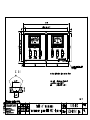
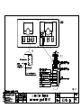
Operating Instruction Manual for Instrument Panel IT 992
Art.-Nr. 930.420
Page 1 / 5
Contents
1.
Description
2.
Safety Information
3.
Operating Instructions and Display
4.
Transport, Storage, Installation
5.
Electrical Installation
6.
Power-Up, Maintenance
7.
Enclosure
1.
Description
The instrument panel IT 992 is used to control the electrical functions of the living-room area.
It is part of a system consisting of a EBL with charging unit, complete 12V distribution and alternatively rod tank sensors or tank sensors for filling level measurement of the water tanks.
Filling level measurement has exclusively been designed for plastic tanks.
1.1
Suitable Accessories (not supplied)
energy system
EBL 99 and it's models and 1x panel cable, 9 x 0,5
rod tank sensors
2x rod tank sensor and 2x seal ring, art.nr. 126.007
(possibly 2x checknut, art.nr. 102.109) 2x sensor cable 5 x 0,5
or tank sensors
10x tanksensor, art.nr. 933.663 2x sensorcable 5 x 0,5
1.2
Technical Data
operating voltage
12V (10 -14.5V), power supply by energy management system
sizes
110 x 304 x 45 incl. connectors (H x W x D in mm)
front panel
aluminium, powder painted
colour
see enclosed table of measurements
2.
Safety Information
* The electrical installation of the motorhome has to be in accordance with current DIN, VDE and
ISO regulations. Manipulations will endanger the safety of persons and the vehicle. Due to the
above mentioned regulations and safety rules, manipulations are therefore prohibited.
* The instrument panel IT 992 must not be modified.
* The connection of the instrument panel has to be done by qualified personel only.
* In the following text special notice should be paid to the signs shown below:
CAUTION !
Electrical current hazard warning.
!
3.
CAUTION !
General hazard warning.
Operating Instructions and Display
230V Mains-Supply Indicator
If yellow LED '230V~' lights up the energy system is connected to mains supply.
See user's manual of energy system, section 6.1 'To Put Into Operation'.
note: operating instruction manual is intended for the owner and has to come with the IT
Schaudt GmbH - Elektrotechnik & App.-bau - 88677 Markdorf - Germany 08.03.2001
Operating Instruction Manual for Instrument Panel IT 992
Art.-Nr. 930.420
Page 2 / 5
Turn on and off 12V supply of living area
actuate switch with ‘ 12V ‘ symbol ...
... in direction of ‘
‘ → 12V supply of living area is turned on.
Green indicator lamp is on.
... in direction of ‘
‘ → 12V supply of living area is turned off.
Green indicator lamp is off.
Note:
The circuits heater, reserve output 4, base light/automatic step are not switched by
12V main switch. They are operative even if 12V supply is switched off.
Only after a energy system shut-down by the battery cut-off switch or after a battery
change do this circuits need to be switched on by actuating 12V-main switch once.
!
Caution !
To avoid unnecessary discharge of the camping battery the 12V supply should
be switched off when leaving the vehicle.
Inquiry of battery voltage
Continous indication of battery voltage from 10 to 15 Volts by 'V / Tank'- instrument (upper scale).
Automatic illumination when used.
Actuate switch in direction of ‘
‘ → Starter battery voltage is indicated.
Actuate switch in direction of ‘
‘ → Camping battery voltage is indicated.
3.1
Evaluation of 'Battery Voltage'
battery
voltage
≤11.0V
11.1V to
13.2V
13.3V to
13.7V
13.8V to
14.4V
>14.6V
... is parked,
without mains supply,
runs on battery
no load:
battery discharged
on load:
battery possibly overloaded
caution: low-level discharge!
standard operation
if at rest * it goes approx.:
<12V: battery discharged
>12.8V: battery full
is allowed to happen only right
after driving or on mains
supply
impossible
!
vehicle ...
... is driving,
mobile
no charge
or
12V-system overloaded
!
caution: low-level discharge!
bad charging (if for longer
time)
or
12V-system overloaded
battery is being charged
... is connected to mains
supply,
runs on 230V
no charge
or
12V-system overloaded
!
caution:low-level discharge!
bad charging (if for longer
time)
or
12V-system overloaded
battery is being charged
battery is being equalize
battery is being equalize
charged
charged
impossible
battery is being overloaded: battery is being overloaded:
regulator of alternator
charger defective
defective
* battery at rest means: The camping battery was not used for several houres. Possibly check voltage in the morning without any load. !! If battery voltage at rest is <12.0V it might be totally discharged !!
!
!
Caution ! Battery Damage
Low-level discharge might permanently damage the battery.
note: operating instruction manual is intended for the owner and has to come with the IT
Schaudt GmbH - Elektrotechnik & App.-bau - 88677 Markdorf - Germany 08.03.2001
!
Operating Instruction Manual for Instrument Panel IT 992
Art.-Nr. 930.420
Page 3 / 5
Red warning indicator ' Alarm' blinks
Optical warning at alarming low camping battery charge.
As soon as the camping battery voltage drops below 11.0V the red warning light 'Alarm'
starts blinking. Any load should now be switched off immediately and the camping battery
has to be recharged.
If camping battery voltage continues to sink and drops below 10.5V, the battery monitor
module of the EBL switches all 12V load off.
See section 3.1 'Battery Voltages' and
the respective sections of the EBL 'Battery Charge' and 'Battery Monitor Module'.
Display of charging current and discharging current of camping battery
The charging and discharging current of the camping battery is displayed permanently by the
’STROM'- meter.
The current meter is automatically illuminated by using the battery voltage- or filling level instrument.
Continous reading of indicating range from 30A discharge current (red range) to
‘no current’ (mid range) to 30A charging current (green range).
Evaluation of ‘charging and discharging currents’
vehicle...
... is driving,
... is parked,
current without mains supply,
reading runs on battery
mobile
on load,
no charge !
red
range
discharge of battery
too much load or
alternator defective
0A
no load
battery fully (or nearly) charged if
charging current decreases with
no load (except refrigerator) from
green range to zero
green
only possible with
battery is being charged,
range
solar-power supply
up to over 30A possible
... is connected to mains supply,
runs on 230V
no charge !
too much load or
alternator defective
battery fully (or nearly) charged if
charging current decreases with
no load from green range to zero
battery is being charged,
up to 16A possible (with additional charger up to 32A)
Inquiry of water tank filling level
Indication of water tank filling levels by 'V / Tank'-meter (lower scale) in steps of empty, 1/4, 1/2, 3/4
and full. Automatic illumination of the meter during inquiry.
Actuate switch in direction of '
‘
→ Filling level of fresh water tank is shown
Actuate switch in direction of ‘
‘
→ Filling level of waste water tank is shown
Note: Inquiry of watertank filling levels is for temporary use only. The utilized method of measurement
is not suitable for continous running or prolonged inquiries.
!
Note:
Caution !
Continous running or prolonged testing will damage rod tank sensors or tank sensors.
If the motor home is not on mains supply the power supply of the water pump should be
turned off during extented periods of no use (eg. at night) as the pump relay has a load
current of approx. 160mA. This adds up to about 4Ah battery drain per day.
!
Caution !
Creepage current discharge of camping battery with pump switch on.
note: operating instruction manual is intended for the owner and has to come with the IT
Schaudt GmbH - Elektrotechnik & App.-bau - 88677 Markdorf - Germany 08.03.2001
Operating Instruction Manual for Instrument Panel IT 992
Art.-Nr. 930.420
Page 4 / 5
Switch on and off of awning light
Actuate switch in direction of ‘
‘
→ Awning light is switched on
Actuate switch in direction of ‘
‘
→ Awning light is switched off
Please see user's manual of motor home manufacturer
4.
Transport, Storage, Installation
4.1
Transport, Storage
* The instrument panel should be stored and transported in a suitable packing and in dry
environment only.
* Storage temperature range : - 10°C to + 50°C.
4.2
Installation
* The instrument panel is designed for use in dry and sufficiantly ventilated environment within a
temperature range of - 10°C to + 45°C.
* It is designed to sink into a cabinet front and has to be fitted on to a stout and level surface by use
of the six provided location holes. Please refer to enclosed table of measurements for mounting size details.
5.
Electrical Installation
* Electrical installation of the instrument panel has to be executed by qualified personel only.
* Electrical connection on the backside of the instrument panel according to enclosed connection instructions.
6.
To Put Into Operation, Maintenance
6.1
To Put Into Operation
* The instrument panel can be operated only in connection with a energy system and water tank filling level measurement accessories. See section 1.1 'Suitable Accessories'.
* After complete connection the instrument panel is operated by the EBL. The appliance is put into
operation as by following sequence: Connect the EBL to mains supply, switch the battery cut-off
switch into 'Ein'-position and actuate 12V main switch on instrument panel.
The the yellow LED '230V~' lights up if the energy system is connected to mains supply.
See user's manual 6.1 'To Put Into Operation'.
6.2
Maintenance, Malfunctions
* The IT 992 is maintenance-free.
* For cleaning of the front panel use a soft moisturized cloth with a mild detergent (no methylated
spirit, paint- thinner, etc.). Liquids must not be allowed to get into the panel.
* Should repairs be necessary, please contact the service department of Schaudt GmbH
ph. 0049-(0)7544-9577-16, eMail: [email protected]
* If it is not possible to see the manufacturer for service (eg. being overseas), necessary repairs
can be carried out by a qualified workshop.
* Unqualified repairs enforce expiration of warranty. The manufacturer Schaudt GmbH disclaims
it's liability and is therefore not liable to resulting damages.
note: operating instruction manual is intended for the owner and has to come with the IT
Schaudt GmbH - Elektrotechnik & App.-bau - 88677 Markdorf - Germany 08.03.2001
Operating Instruction Manual for Instrument Panel IT 992
Art.-Nr. 930.420
7.
Page 5 / 5
Enclosures
To this operating instruction manual belongs the enclosed the connection diagram and the
dimension list to IT 992, art. nr. 930.420.
This operating instructions manual with all it's enclosures must be delivered together with the
IT 992, art.nr. 911.420. It must be part of the instruction manual if it is part of a system
installed in a motorhome.
7.1
EC declaration of conformity
We hereby certify that the type of construction of the instrument panel IT 992
corresponds accordingly to approbiate provisions:
Electromagnetic compabitibility guide line
89/336/EWG mit Änderung 92/31/EWG
The EC declaration of conformity in original is available and can be looked at any time.
Manufacturer: Schaudt GmbH, Elektrotechnik & Apparatebau
Address:
Daimlerstraße 5
88677 Markdorf
Germany
note: operating instruction manual is intended for the owner and has to come with the IT
Schaudt GmbH - Elektrotechnik & App.-bau - 88677 Markdorf - Germany 08.03.2001
ALARM
!
IT 992
230V
12V