1
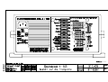
Operating Instruction Manual
Energy Management System EBL 4-105 Art.-No 911.406
Page 1 / 7
Contents
1.
Description
2.
Safety Information
3.
Operating Instructions
4.
Transport, Storage, Installation
5.
Electrical Installation
6.
Power-Up, Shut-Down, Maintenance
7.
Malfunctions
8.
Enclosure
1.
Description
The energy system EBL 4-105 contains the charging module LA 204-5, the complete 12V
distribution, fuse protected 12V circuits and a connector for a solar regulator.
To operate the energy system and to control the living-area functions including accessories,
an instrument panel is compulsory.
1.1
Suitable Accessories (not supplied)
control and switch panel
instrument panel IT 105 and its versions
solar regulator
LR 1214, art. no 922.205, for solar modules with a maximum total
current of 14A, with 3-p connector and a 0.5 m connecting cable.
1.2
Technical Data
1.2.1
General Data
sizes (h x w x d in mm)
130 x 275 x 170 incl. mounting feet
weight
4 kg
cabinet
PA (Polyamid), Gentian blue RAL 5010
frontpanel
aluminium, powder painted, light grey RAL 7035
1.2.2
Electrical Data
mains supply
* 230 V, + 6% - 10 %, 50 Hz, safety class 1
power consumption
* 250 VA
suitable batteries
* 6 cell lead-acid or lead-gel batteries, more than 35Ah
steady load off
living-area battery
* without mains supply, battery alarm off, battery voltage 12.6V
and with IT 105: 0.6mA
load current of D+ output
of alternator by EBL
* approx 0.5A without load at the D+ terminal,
see block diagram
Note: this user manual is intented for the owner and has to come with the EBL
Schaudt GmbH, Elektrotechnik & Apparatebau, Daimlerstraße 5, D-88677 Markdorf, Tel +49 7544 9577-0, Fax +49 7544 9577-29, www.schaudt-gmbh.de 16.03.2004
Operating Instruction Manual
Energy Management System EBL 4-105 Art.-No 911.406
1.2.2.1
... on mains supply
Page 2 / 7
Battery charging ...
living-area battery:
control system
* thyristor controller
charging characteristic
* IWUoU
maximum charging voltage * 14.4V
charging current
* 10A arithmetic mean or 15A eff at 230V mains supply and 12.0V
charging voltage. The charging current is mains supply dependent.
floating voltage
* 13.8V, automatic change-over
new charging cycle,
change-over to boost-charge * if battery voltage is approx < 13.8V
3-phase characteristic:
* boost-charge at 10A max
(arithmetic mean, electronically limited)
up to maximum charging voltage,
* then equalise-charge at constant 14.4V,
selectable: 0.3h duration for lead-acid,
6h duration for lead-gel batteries,
U charge
V
charging characteristic of EBL 4-105
'boost-charge'
I
'equalise'
Uo
'float'
U
14.4
13.8
20 min with lead-acid
6h with lead-gel
* then automatic change-over to float-charge
at 13.8V
time
If due to high loads the float voltage of 13.8V can not be provided, the battery charger switches
over from float to boost-charge.
safety circuits
* short-circuit and reverse-polarity protected,
charger needs a connected battery with a voltage of > 2.5V
* safety fuse in mains supply, 1.6A slow
* over-temperature switch in transformer
starter battery:
charging current
* trickle-charge to starter battery with max 2A
...by solar regulator
max. allowed charging
current
* 10A, only the living-area battery gets charged
...while driving
charging current
* simultaneous charging of starter and living-area battery by alternator,
batteries in parallel by cut-off relay, maximum charging current of
living-area battery by alternator must not exceed 30A.
See block diagram.
Note: this user manual is intented for the owner and has to come with the EBL
Schaudt GmbH, Elektrotechnik & Apparatebau, Daimlerstraße 5, D-88677 Markdorf, Tel +49 7544 9577-0, Fax +49 7544 9577-29, www.schaudt-gmbh.de 16.03.2004
Operating Instruction Manual
Energy Management System EBL 4-105 Art.-No 911.406
2.
Page 3 / 7
Safety Information
* The electrical installation of the motorhome has to be in accordance with current DIN-, VDE- and
ISO-regulations. Alterations will endanger the safety of persons and the vehicle.
Due to the above mentioned regulations and safety rules, alterations are therefore prohibited.
* The connection of the EBL to the mains supply has to be in accordance to national installation
regulations.
* The energy management system EBL 4-105 must not be modified.
* The connection of the energy system should be carried out by qualified personnel only, and must be
conform to specifications mentioned in this operating instruction manual:
see instruction manual
section 4.2 'Installation'
section 5
'Electrical Installation'
block diagram EBL 4-105
and in enclosure
* In the following text special notice should be paid to the signs shown below:
CAUTION !
Electrical current hazard warning.
CAUTION !
General hazard warning.
3.
Operating Instructions
3.1
Controls
CAUTION !
Rear side of the device gets hot during operation. Do not touch.
12V fuses
Pluggable automotive safety fuses
Battery-Type
Selector Switch
Prior to actuating this frontside switch, the energy system must
be disconnected from the 230 volt electrical supply by seperating
the vehicle from mains supply.
Before operating the energy system, the switch must be set according
to the type of battery being used (lead-acid or lead-gel). The selector
switch ensures an optimum charge of the connected battery type.
To actuate use a thin tool, eg a pencil tip.
Caution !
Incorrect setting of the battery-type switch could cause damage to the batteries and may
possibly produce an explosive gassing hazard.
Note: this user manual is intented for the owner and has to come with the EBL
Schaudt GmbH, Elektrotechnik & Apparatebau, Daimlerstraße 5, D-88677 Markdorf, Tel +49 7544 9577-0, Fax +49 7544 9577-29, www.schaudt-gmbh.de 16.03.2004
Operating Instruction Manual
Energy Management System EBL 4-105 Art.-No 911.406
3.2
Page 4 / 7
Relay Functions
battery cut-off relay
This relay seperates the starter and living-area battery when the engine is
not running and if there is no voltage on terminal 'D+'.
Both batteries are connected in parallel and therefore simultaneously
charged while engine is running.
main-switch relay,
bistable
This relay is controlled by the push-button switch on the instrument panel
'12V EIN/AUS'. It switches all 12V load off, except the circuits heater,
compressor refrigerator and courtesy light/ automatic step.
refrigerator cut-off relay
This relay controls the power supply of the absorption type refrigerator.
absorption type refrigerator The refrigerator gets power from the starter battery only, if the engine
is running and if there is a voltage on terminal 'D+'.
charging relay battery 1
starter battery
This relay automatically provides a 2A trickle-charge to
the starter battery if mains supply is on.
4.
Transport, Storage, Installation
4.1
Transport, Storage
* The energy system should be stored and transported
in suitable packing and in a dry environment only.
* Storage temperature range : - 20 °C to + 70 °C.
4.2
Installation
* The energy system has been designed for floor mounting.
* It has to be fitted onto a stout and level surface by use of
the four provided mounting feet.
* The energy system is designed for use in a dry and
sufficiently ventilated environment within a temperature range of - 10 °C to + 45 °C.
* A minimum distance of 5 cm to the surrounding equipment has to be maintained above and to all sides.
In operation a temperature of max + 45 °C at a distance of 2.5 cm to the sides must not be
exceeded.
Caution !
Danger of overheating if distances to equipment are insufficient, or if ventilation is blocked.
Note: this user manual is intented for the owner and has to come with the EBL
Schaudt GmbH, Elektrotechnik & Apparatebau, Daimlerstraße 5, D-88677 Markdorf, Tel +49 7544 9577-0, Fax +49 7544 9577-29, www.schaudt-gmbh.de 16.03.2004
Operating Instruction Manual
Energy Management System EBL 4-105 Art.-No 911.406
5.
Page 5 / 7
Electrical Installation
* Electrical installation should be carried out by qualified personnel only.
* The device must be used only with a living-area battery.
Caution !
The energy system must not be used without a connected living-area battery,
otherwise, connected appliances might be damaged in unfavourable conditions.
* Electrical connection is made on the frontside, according to enclosed block diagram.
* For installation purposes, the mains plug or mains supply of the vehicle must be disconnected.
Caution !
Danger of life due to electrical shock or danger of burning with a defective mains
cable, incorrect connection or service work with mains supply on.
* Electrical connection has to be in accordance to the following sequence:
1.
all socket connectors on frontpanel of energy system
2.
battery cables on energy system, screw terminals on rear panel
3.
battery cables on battery terminals
4.
230V mains supply plug
* Disconnection has to be executed vice versa.
5.1
230V Mains Supply
* The power cord has to be connected to an earthing contact socket outlet.
* The power cord must be a H05VV-F 3x1.5 cable.
* For connection, the mains plug or mains supply of the vehicle has to be disconnected.
Caution !
Danger of life due to electrical shock or danger of burning with a defective mains
cable, incorrect connection or service work with mains supply on.
5.2
Batteries, Battery-Sense Cable, Refrigerator and D+ (Alternator)
* Leads have to be fused according to their cross-sections.
Maximum allowed fuse ratings:
batteries
sensor cable battery 2
30A
2A
D+ (alternator)
2A
* Fuses need to be installed close to the battery terminals or alternator for short circuit protection
of the leads.
* The negative pole of the living-area battery has to be connected to the negative pole of the starter
battery externally.
Caution !
Danger of burning because of incorrect connection and fusing.
* The energy system has to be used exclusively on 12V power systems with rechargeable 6-cell
lead-acid or lead-gel batteries.
Caution !
Unsuitable batteries will be damaged.
Note: this user manual is intented for the owner and has to come with the EBL
Schaudt GmbH, Elektrotechnik & Apparatebau, Daimlerstraße 5, D-88677 Markdorf, Tel +49 7544 9577-0, Fax +49 7544 9577-29, www.schaudt-gmbh.de 16.03.2004
Operating Instruction Manual
Energy Management System EBL 4-105 Art.-No 911.406
Page 6 / 7
* The batteries have to be mounted in sufficiently ventilated areas or must be fitted with vent lines.
Please refer to installation instructions of the battery manufacturer.
Caution !
Exploding hazard by detonating gas with defective batteries, defective energy system
or at too high battery temperature (>30°C).
5.3
12V-Load
* The choice of battery cable size dimensions has to comply with EN 1648-1 or –2.
Maximum current drain of the load must not exceed the respective fuse rating.
6.
To Put Into Operation, Shut-Down, Maintenance
6.1
To Put Into Operation
* Prior to power-up special attention must be paid to:
1.
2.
6.2
Properly connected living-area battery
Correctly selected battery-type switch. See section 3.1 'Controls'.
Shut-Down
* Before long periods of nonusage of the motorhome (eg during wintertime), the living-area battery
should be disconnected from the 12V system. Switch off 12V main-switch on instrument panel and
disconnect cables at the battery terminals.
Caution !
Please note, the anti-freeze valve of the water heater opens automatically if the energy
system is disconnected from the living-area battery.
* Before and after long periods of nonusage (eg during wintertime), the vehicle should be hooked
up to mains supply to fully recharge the batteries for a minimum of 12 hours (80Ah battery) or
16 hours (160Ah battery).
Caution !
To prevent battery damage the battery should be fully charged before shut-down
of the vehicle.
Note:
It is possible to recharge the batteries by the built-in charging unit, by solar regulator or by
alternator even if the main switch on the instrument panel is off.
6.3
Maintenance
* The energy system EBL 4-105 is maintenance-free.
* For cleaning use a soft moisturized cloth with a mild detergent. Do not use methylated spirit,
paint thinner, etc. Liquids must not be allowed to get into the cabinet.
7.
Malfunctions
* If due to high surrounding temperature or bad ventilation the EBL gets too hot, the charger unit
switches off until the temperature has dropped to a save level. However, overheating should in
any case be prevented.
* Should repairs be necessary, please contact the service department of Schaudt GmbH,
ph. +49 7544 9577-16, e-mail [email protected]
* If it is not possible to see the manufacturer for service, eg being overseas, necessary repairs can be
carried out by a qualified workshop.
Note: this user manual is intented for the owner and has to come with the EBL
Schaudt GmbH, Elektrotechnik & Apparatebau, Daimlerstraße 5, D-88677 Markdorf, Tel +49 7544 9577-0, Fax +49 7544 9577-29, www.schaudt-gmbh.de 16.03.2004
Operating Instruction Manual
Energy Management System EBL 4-105 Art.-No 911.406
Page 7 / 7
* Unqualified repairs would invalidate warranty. The manufacturer Schaudt GmbH disclaims its
liability and is therefore not liable to resulting damages.
8.
Enclosures
To this operating instruction manual belongs the enclosed schematic diagram and the drawing
of the front view of the energy system EBL 4-105, art.no 911.406.
This operating instruction manual with all its enclosures must be delivered together with the
energy system EBL 4-105, art.no 911.406.
It has to be part of the instruction manual if it is part of a system installed in a motorhome.
8.1
EC declaration of conformity
We hereby certify that the type of construction of the energy management system EBL 4-105
corresponds accordingly to appropriate provisions:
EC low-voltage guide line
73/23/EWG amendment of 22.07.93
Electromagnetic compabitibility guide line
89/336/EWG amended to 92/31/EWG
Employed standards and technical specifications, particularly:
DIN EN 60335-1:1994 +A11+A1+A12+A13+A14
DIN EN 60335-2-29:1996 + A11
DIN EN 50081-1:3.1993
DIN EN 50082-1:3.1993
DIN EN 61000-3-2:2000
The EC declaration of conformity in original is available and can be looked at any time.
Manufacturer: Schaudt GmbH, Elektrotechnik & Apparatebau
Address:
Daimlerstraße 5
88677 Markdorf
Germany
Note: this user manual is intented for the owner and has to come with the EBL
Schaudt GmbH, Elektrotechnik & Apparatebau, Daimlerstraße 5, D-88677 Markdorf, Tel +49 7544 9577-0, Fax +49 7544 9577-29, www.schaudt-gmbh.de 16.03.2004


![Acctiva 12-10, Acctiva 24-5, Acctiva Classic [42,0410,0457]](http://vs1.manualzilla.com/store/data/006739146_1-5bfec39fc9ef331a1fb74149196b237e-150x150.png)