1
Operating Instruction Manual
Development Tool
Hilscher Gesellschaft für Systemautomation mbH
www.hilscher.com
DOC100316OI15EN | Revision 15 | English | 2012-07 | Released | Public
Introduction
2/197
Table of Contents
1
INTRODUCTION.........................................................................................................4
1.1
About this Manual .......................................................................................................4
1.1.1
1.1.2
1.2
Contents of the Product CD........................................................................................6
1.2.1
1.2.2
1.3
2
Copyright ..............................................................................................................7
Important Notes ....................................................................................................7
Exclusion of Liability .............................................................................................8
Warranty ...............................................................................................................8
Export Regulations ...............................................................................................9
Registered Trademarks........................................................................................9
Licenses......................................................................................................................9
QVIS BRIEF OVERVIEW ..........................................................................................10
2.1
2.2
2.3
3
Hardware ..............................................................................................................6
Software ...............................................................................................................6
Legal Notes.................................................................................................................7
1.4.1
1.4.2
1.4.3
1.4.4
1.4.5
1.4.6
1.5
Directory Structure of the CD ...............................................................................6
QViS Documentations ..........................................................................................6
Reference to Hardware/Software ...............................................................................6
1.3.1
1.3.2
1.4
Conventions in this Manual ..................................................................................4
List of Revisions ...................................................................................................5
Installing QViS ..........................................................................................................10
Launching QViS........................................................................................................11
Layout and Areas of QViS ........................................................................................12
CREATING A PROJECT WITH QVIS .......................................................................13
3.1
The Project Creation Assistant .................................................................................13
3.1.1
3.1.2
3.2
The Page Browser ....................................................................................................16
3.2.1
3.2.2
3.3
What Is the Project Creation Assistant?.............................................................13
How Does the Project Creation Assistant Function? .........................................13
What Is the Page Browser?................................................................................16
How Does the Page Browser Function? ............................................................17
The Page Editor........................................................................................................19
3.3.1
3.3.2
3.3.3
3.3.4
3.3.5
3.3.6
3.3.7
3.3.8
3.3.9
3.3.10
3.3.11
3.3.12
3.3.13
3.3.14
What Is a Page? .................................................................................................19
How to Operate It ...............................................................................................20
The Page Properties ..........................................................................................22
Element Variable ................................................................................................23
Element Symbol .................................................................................................28
Element Text ......................................................................................................35
Element Button ...................................................................................................42
Element Bargraph...............................................................................................49
Element Arc ........................................................................................................54
Element Pointer Instrument................................................................................59
Element Vector Graphic .....................................................................................65
Element List........................................................................................................69
Element Trend ....................................................................................................73
The Object ..........................................................................................................76
QViS | Development Tool
DOC100316OI15EN | Revision 15 | English | 2012-07 | Released | Public
© Hilscher, 2010-2012
Introduction
3.4
3/197
The Feet Tabs ..........................................................................................................81
3.4.1
3.4.2
3.4.3
3.4.4
3.4.5
3.5
Project Settings.........................................................................................................94
3.5.1
3.5.2
3.5.3
3.5.4
3.5.5
3.5.6
3.5.7
3.5.8
3.5.9
3.5.10
3.5.11
3.6
3.7
3.8
3.9
4
General...............................................................................................................95
Pages .................................................................................................................96
Languages..........................................................................................................98
Key Lists .............................................................................................................99
Units .................................................................................................................100
Passwords ........................................................................................................101
Alarms ..............................................................................................................102
Alarm History ....................................................................................................104
Target ...............................................................................................................106
Command Interface ..........................................................................................107
Character Sets..................................................................................................110
The Main Menu.......................................................................................................112
Building the Project.................................................................................................114
Simulating the Project.............................................................................................115
Copying the Project to the Target System ..............................................................117
APPLICATION EXAMPLES ....................................................................................119
4.1
4.2
4.3
Variable Lists ..........................................................................................................119
Trend ......................................................................................................................125
Handling Alarms .....................................................................................................133
4.3.1
4.3.2
4.4
4.5
4.6
Using Default Character Sets...........................................................................161
Creating a Character Set..................................................................................162
Adding Chinese Characters .............................................................................165
Managing Recipes ..................................................................................................170
Importing Variables.................................................................................................177
4.10.1
4.10.2
4.10.3
4.11
Using Default Keypads.....................................................................................154
Creating Your Own Keypads............................................................................155
Online Help .............................................................................................................157
Using and Creating Character Sets ........................................................................161
4.8.1
4.8.2
4.8.3
4.9
4.10
Creating a Multi-language Project ....................................................................143
Creating Text Lists Using MS Excel .................................................................147
Switching Units .......................................................................................................150
Using and Creating Keypads ..................................................................................154
4.6.1
4.6.2
4.7
4.8
Creating an Alarm List......................................................................................133
Creating an Alarm History List..........................................................................138
Switching Languages..............................................................................................143
4.4.1
4.4.2
5
Messages ...........................................................................................................81
Symbols..............................................................................................................82
Texts...................................................................................................................83
Variables.............................................................................................................85
Objects ...............................................................................................................94
Import from CoDeSys V3 for Local Access......................................................177
Importing via the Symbolyzer ...........................................................................181
Importing from a Simatic Project ......................................................................187
Scaling (Multiplier) ..................................................................................................195
CONTACTS.............................................................................................................197
QViS | Development Tool
DOC100316OI15EN | Revision 15 | English | 2012-07 | Released | Public
© Hilscher, 2010-2012
Introduction
1
4/197
Introduction
1.1
About this Manual
This manual contains a description on working with the visualization
software QViS, developed by Hilscher Gesellschaft für Systemautomation
mbH. It includes instructions on installing the software, creating projects
and several application examples.
1.1.1
Conventions in this Manual
Instructions, the result of an action step or notes are marked as follows:
Instructions:
! <Instruction>
or
1. <Instruction>
2. <Instruction>
Results:
" <Result>
Notes:
Note: <Note>
QViS | Development Tool
DOC100316OI15EN | Revision 15 | English | 2012-07 | Released | Public
© Hilscher, 2010-2012
Introduction
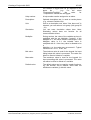
1.1.2
5/197
List of Revisions
Revision
Date
Chapter
Changes
1
2010-03-05
Everything
Created
2
2010-03-12
Everything
Updated
3
2010-03-18
Everything
Updated
4
2010-03-26
Everything
Updated
5
2010-04-12
Page
Editor
Added ScaleMaker
6
2010-06-18
Importing
Variables
Updated Example "Importing Variables", added
Appendix Hilscher XML Format
7
2010-07-14
Hilscher
XML
Format
Extended data types
8
2010-10-11
Element
Symbol/
Text
Project
Settings
The elements "Dynamic Text" and "Static Text" were
consolidated to the element "Text."
The elements "Dynamic Symbol" and "Static Symbol"
were consolidated to the element "Symbol."
Added Command Interface
9
2010-12-13
Variables
Variables were extended by the property "Multiplier."
10
2011-03-18
Everything
Updated
11
2011-03-30
Page
Editor
Condition Blink was deleted
12
2011-06-27
Element
Button
Deleted Print Functions
13
2011-10-18
Chapters
1 to 3
Replaced screenshots, revised and supplemented
texts.
14
2012-01-20
Chapters
4 to 6
Chapter 4) Replaced screenshots, revised and
supplemented texts.
Chapter 5) Deleted XML Format Description for
Importing Variables, as it is only relevant for OEM
drives.
Chapter 6 became Chapter 5.
Chapters
1 to 3
Corrected formatting errors and spelling mistakes,
textual adaptations.
3.3.7.3
Added the note on "modify variable directly" in 3.3.7.3.
15
2012-07-12
QViS | Development Tool
DOC100316OI15EN | Revision 15 | English | 2012-07 | Released | Public
© Hilscher, 2010-2012
Introduction
1.2
6/197
Contents of the Product CD
• This Operating Instruction Manual is a part of different products and
distributions. Apart from other components, the scope includes:
• QViS (configuration tool for Windows PCs)
• QViSRT (Runtime/Firmware)
• Documentation
• Examples
1.2.1
Directory Structure of the CD
Please refer to the CD Booklet for the directory structure and exact content
of the product CD.
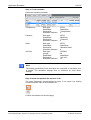
1.2.2
QViS Documentations
The following overview of documents provides details in which manual you
can find further information on topical contents.
Manual
Content
Document Name
Operating Instruction Manual for QViS Development Tool
Manual
QViS
QViS - Development Tool OI xx EN.pdf
Application Note:
QViS Driver
Configuration
Fieldbus Configuration in Detail
QViS-DriverConfiguration_AN_DE.pdf
Application Note:
QViS Command
Interface
Controlling Several QViS Functions via any
Drive out of the PLC
QViS-CommandInterface_AN_DE.pdf
1.3
1.3.1
Reference to Hardware/Software
Hardware
QViS can create visualizations for QViS Runtimes (QViSRT) that run on
different hardware platforms under various operating systems. For this
reason, the information in this manual has been written in the most general
terms possible.
1.3.2
Software
The prerequisite for using QViS is a Windows XP or Windows 7 compatible
computer. Furthermore, the .NET Framework in Version 3.5 must be
installed.
QViS | Development Tool
DOC100316OI15EN | Revision 15 | English | 2012-07 | Released | Public
© Hilscher, 2010-2012
Introduction
1.4
1.4.1
7/197
Legal Notes
Copyright
© Hilscher, 2010-2012, Hilscher Gesellschaft für Systemautomation mbH
All rights reserved.
The images, photographs and texts in the accompanying material (user
manual, accompanying texts, documentation, etc.) are protected by
German and international copyright law as well as international trade and
protection provisions. You are not authorized to duplicate these in whole or
in part using technical or mechanical methods (printing, photocopying or
other methods), to manipulate or transfer using electronic systems without
prior written consent. You are not permitted to make changes to copyright
notices, markings, trademarks or ownership declarations. The included
diagrams do not take the patent situation into account. The company
names and product descriptions included in this document may be
trademarks or brands of the respective owners and may be trademarked or
patented. Any form of further use requires the explicit consent of the
respective rights owner.
1.4.2
Important Notes
The user manual, accompanying texts and the documentation were created
for the use of the products by qualified experts, however, errors cannot be
ruled out. For this reason, no guarantee can be made and neither juristic
responsibility for erroneous information nor any liability can be assumed.
Descriptions, accompanying texts and documentation included in the user
manual do not present a guarantee nor any information about proper use
as stipulated in the contract or a warranted feature. It cannot be ruled out
that the user manual, the accompanying texts and the documentation do
not correspond exactly to the described features, standards or other data of
the delivered product. No warranty or guarantee regarding the correctness
or accuracy of the information is assumed.
We reserve the right to change our products and their specification as well
as related user manuals, accompanying texts and documentation at all
times and without advance notice, without obligation to report the change.
Changes will be included in future manuals and do not constitute any
obligations. There is no entitlement to revisions of delivered documents.
The manual delivered with the product applies.
Hilscher Gesellschaft für Systemautomation mbH is not liable under any
circumstances for direct, indirect, incidental or follow-on damage or loss of
earnings resulting from the use of the information contained in this
publication.
QViS | Development Tool
DOC100316OI15EN | Revision 15 | English | 2012-07 | Released | Public
© Hilscher, 2010-2012
Introduction
1.4.3
8/197
Exclusion of Liability
The software was produced and tested with utmost care by Hilscher
Gesellschaft für Systemautomation mbH and is made available as is. No
warranty can be assumed for the performance and flawlessness of the
software for all usage conditions and cases and for the results produced
when utilized by the user. Liability for any damages that may result from the
use of the hardware or software or related documents, is limited to cases of
intent or grossly negligent violation of significant contractual obligations.
Indemnity claims for the violation of significant contractual obligations are
limited to damages that are foreseeable and typical for this type of contract.
It is strictly prohibited to use the software in the following areas:
• for military purposes or in weapon systems;
• for the design, construction, maintenance or operation of nuclear
facilities;
• in air traffic control systems, air traffic or air traffic communication
systems;
• in life support systems;
• in systems in which failures in the software could lead to personal injury
or injuries leading to death.
We inform you that the software was not developed for use in dangerous
environments requiring fail-proof control mechanisms. Use of the software
in such an environment occurs at your own risk. No liability is assumed for
damages or losses due to unauthorized use.
1.4.4
Warranty
Although the hardware and software was developed with utmost care and
tested intensively, Hilscher Gesellschaft für Systemautomation mbH does
not guarantee its suitability for any purpose not confirmed in writing. It
cannot be guaranteed that the hardware and software will meet your
requirements, that the use of the software operates without interruption and
that the software is free of errors. No guarantee is made regarding
infringements, violations of patents, rights of ownership or the freedom from
interference by third parties. No additional guarantees or assurances are
made regarding marketability, freedom of defect of title, integration or
usability for certain purposes unless they are required in accordance with
the law and cannot be limited. Warranty claims are limited to the right to
claim rectification.
QViS | Development Tool
DOC100316OI15EN | Revision 15 | English | 2012-07 | Released | Public
© Hilscher, 2010-2012
Introduction
1.4.5
9/197
Export Regulations
The delivered product (including the technical data) is subject to export or
import laws as well as the associated regulations of different counters, in
particular those of Germany and the USA. The software may not be
exported to countries where this is prohibited by the United States Export
Administration Act and its additional provisions. You are obligated to
comply with the regulations at your personal responsibility. We wish to
inform you that you may require permission from state authorities to export,
re-export or import the product.
1.4.6
Registered Trademarks
Windows® XP and Windows® 7 are registered trademarks of the Microsoft
Corporation.
1.5
Licenses
A license is required when using QViS Runtime, which depending on the
hardware and the operating system used is either available on the existing
system (e.g., Security Memory), or must be separately obtained.
QViS | Development Tool
DOC100316OI15EN | Revision 15 | English | 2012-07 | Released | Public
© Hilscher, 2010-2012
QViS Brief Overview
2
10/197
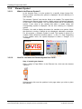
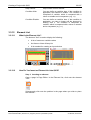
QViS Brief Overview
QViS is visualization software. QViS is comprised of two components:
• QViS, the development tool, executable on Windows PCs
• QViSRT, the runtime system, executable on a target device (HMI)
With the QViS development tool, images are compiled on the PC and
linked with variables. The QViSRT runtime system displays theses images
on the target device and provides the variables with values.
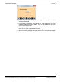
Overview:
1st step:
Create a project on a
PC with QViS
2nd step:
Build
&
Download
3rd step:
2.1
Build the project and
transmit it to the target
device
Project now runs on a
target device and
QViSRT
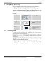
Installing QViS
To install QViS, the QViS setup (e.g., Setup_QViS_V3.1.1.2.exe) must be
executed and the instructions followed.
During setup, it is first checked whether .NET Framework 3.5SP1 is
installed. Should it not be, it is automatically installed before the QViS setup
is continued.
QViS is installed in the selected installation directory. In addition, examples
of a QViS project and text management in Excel are installed in the
directory "My Documents\QViS Projects."
• Example: "My Documents\QViS Projects\Example1_320x240"
• Text management in Excel: " My Documents\QViS Projects\QViSTexts.xls"
QViS | Development Tool
DOC100316OI15EN | Revision 15 | English | 2012-07 | Released | Public
© Hilscher, 2010-2012
QViS Brief Overview
2.2
11/197
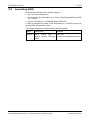
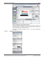
Launching QViS
QViS can be launched via the following options:
• Via a link on the Desktop, or
• Via an entry in the Start Menu, e.g., under "Start/Program/Hilscher/QViS
V3.1.1/QViS"
• Via the command line "<Installationspfad>\QViS.exe"
If QViS is prompted by means of the command line, a specific project can
be launched via parameter values.
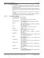
The following parameter values to QViS.exe are possible:
Name
Description
-project=
QViS should open a QViS.exe
specific project following "-project=c:\temp\MyProject.qpr"
Start.
QViS | Development Tool
DOC100316OI15EN | Revision 15 | English | 2012-07 | Released | Public
Example
© Hilscher, 2010-2012
QViS Brief Overview
2.3
12/197
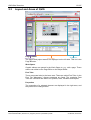
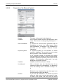
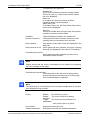
Layout and Areas of QViS
Menu and Toolbar
Work Space
Page Browser
Properties
Page Browser
Feet Tabs
The pages and project names are displayed on the left side. This list is the
Page Browser.
Work Space
Graphic editors are opened in the Work Space to, e.g., edit a page. These
editors can either be the Page Editor or the Object Editor.
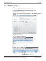
Feet Tabs
There are several tabs in the lower area. These are called Feet Tabs. In the
Feet Tab "Messages," diverse messages are listed. The remaining Feet
Tabs are a browser and editors for symbols, texts, variables and objects.
Properties
The properties of a selected element are displayed in the right area, and
they can also be changed here.
QViS | Development Tool
DOC100316OI15EN | Revision 15 | English | 2012-07 | Released | Public
© Hilscher, 2010-2012
Creating a Project with QViS
3
13/197
Creating a Project with QViS
3.1
3.1.1
The Project Creation Assistant
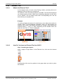
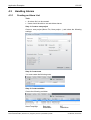
What Is the Project Creation Assistant?
The Project Creation Assistant helps the user in creating a new QViS
project.
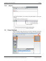
3.1.2
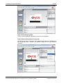
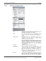
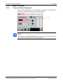
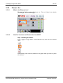
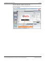
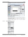
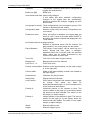
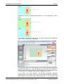
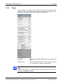
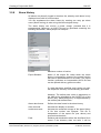
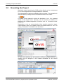
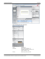
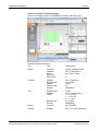
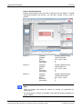
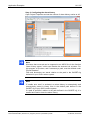
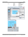
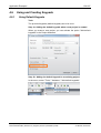
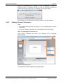
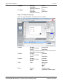
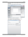
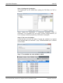
How Does the Project Creation Assistant Function?
The Project Creation Assistant can be launched by selecting "File" > "New
project…" in the menu:
QViS | Development Tool
DOC100316OI15EN | Revision 15 | English | 2012-07 | Released | Public
© Hilscher, 2010-2012
Creating a Project with QViS
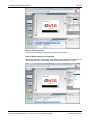
14/197
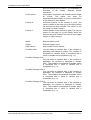
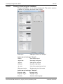
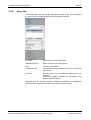
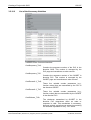
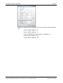
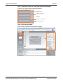
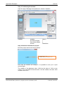
The following settings are possible:
Project name:
Name of the QViS project to be created. The project is created in a folder
that likewise bears this name.
Project path:
Path where the project to be created is to be stored. In this path, a sub-file
bearing the project name is created. All files and folders belonging to the
project are saved in this sub-file.
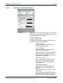
Target device:
Select the target system on which the QViS project to be created is to run.
Only installed target systems, as well as a freely programmable device
named "User defined," are available for selection.
Display width:
The horizontal resolution of the target device's display in pixel.
Display height:
The vertical resolution of the target device's display in pixel.
Download mechanism:
The preferred download mechanism for copying the created project to the
target device.
Communication driver:
The communication driver that QViS Runtime is to use. This can be, e.g., a
communication driver that can communicate with an PLC. The
communication driver is the link between QViS Runtime and the data to be
displayed or written.
QViS | Development Tool
DOC100316OI15EN | Revision 15 | English | 2012-07 | Released | Public
© Hilscher, 2010-2012
Creating a Project with QViS
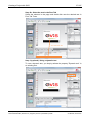
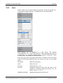
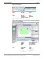
15/197
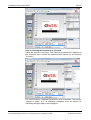
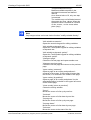
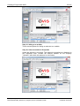
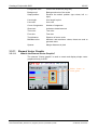
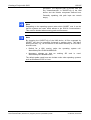
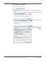
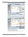
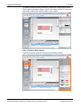
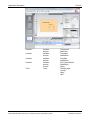
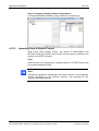
Create a start page:
If this checkbox is selected, after creating the new project, an empty start
page is generated, which is added to the project and it is also immediately
opened in the Editor.
Add default character sets:
If this checkbox is selected, after creating the new project, the standard
QViS default character sets are added to the project.
Add default keypads:
If this checkbox is selected, after creating the new project, the standard
QViS default keypads, such as e.g., a numeric keypad, are added to the
project.
Add trend pages:
If this checkbox is selected, after creating the new project, a page with a
trend and a trend configuration page are added to the project.
Should you not see the setting "Add trend pages," then Trend has been
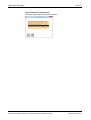
deactivated.
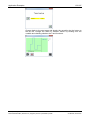
After clicking the button "Create project" a QViS project is created:
QViS | Development Tool
DOC100316OI15EN | Revision 15 | English | 2012-07 | Released | Public
© Hilscher, 2010-2012
Creating a Project with QViS
3.2
3.2.1
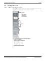
16/197
The Page Browser
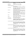
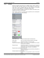
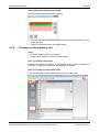
What Is the Page Browser?
The Page Browser is located on the left side of the QViS main window. The
Page Browser lists all pages of the opened QViS project.
Tool bar
Project name
and button to
project settings
Pages
The Page Browser offers the following options:
• Create a new page
• Remove pages in the project
• Rename pages
• Open pages for editing
• Display the project name
• Open the project properties
QViS | Development Tool
DOC100316OI15EN | Revision 15 | English | 2012-07 | Released | Public
© Hilscher, 2010-2012
Creating a Project with QViS
3.2.2
17/197
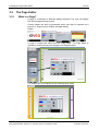
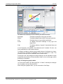
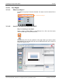
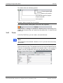
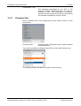
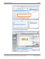
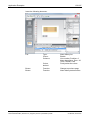
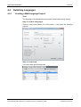
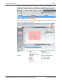
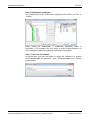
How Does the Page Browser Function?
In the Page Browser, you see a list with numerous entries. The first entry is
always the project name:
When the project name is selected, the project properties are opened in the
area "Properties":
The project properties are described in the Chapter "Project Settings."
You can change the project name by either selecting the project name and
then pressing the F2 key, or via a right click on the project name and then
selecting "rename project" in the context menu.
QViS | Development Tool
DOC100316OI15EN | Revision 15 | English | 2012-07 | Released | Public
© Hilscher, 2010-2012
Creating a Project with QViS
18/197
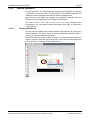
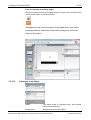
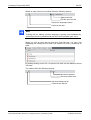
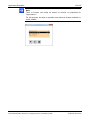
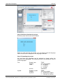
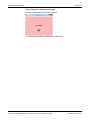
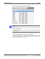
All further entries are QViS pages. An entry is displayed in this list for each
page in the QViS project:
By double clicking onto a page, the page is opened with the PageEditor.
The following context menu is displayed by right clicking onto a page:
• Context menu "delete page" or "remove page":
Delete/Remove the selected page from the QViS project.
• Context menu "rename page" or the "F2" key:
Rename the selected page.
• Context menu "move up/down/to top/to bottom":
Move the selected page within the Page Browser.
The toolbar above the list offers the following functions:
Move the selected page up or down
Add a new (empty) page to the project
QViS | Development Tool
DOC100316OI15EN | Revision 15 | English | 2012-07 | Released | Public
© Hilscher, 2010-2012
Creating a Project with QViS
3.3
3.3.1
19/197
The Page Editor
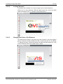
What Is a Page?
A page is a collection of different display elements. The user can display
the various pages during runtime.
Overlay pages can also be generated, which can then be opened via a
page (e.g., keypad, input window, amongst others).
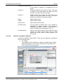
Pages:
A page is created and edited with the Page Editor. The Page Editor is
opened by double clicking onto a page in the Page Browser:
Double click
PageEditor
The Page Editor is comprised of the following three areas:
Element list
Work space
QViS | Development Tool
DOC100316OI15EN | Revision 15 | English | 2012-07 | Released | Public
Auxiliary tools
© Hilscher, 2010-2012
Creating a Project with QViS
3.3.2
20/197
How to Operate It
In the Page Editor, the individual page elements are displayed. An element
is selected via a mouse click. The properties of the element selected are
displayed in the Properties area and can also be changed here.
New elements are added by selecting the respective element from the
Element List and positioning it on the page (Work space).
The zoom level of the view can be set in the area Auxiliary tools.
Furthermore, you can either activate the auxiliary tool "grid" or configure it
via a right click.
3.3.2.1
Grouping Elements
A group can be created from several elements. All elements in a group are
moved together. To either move or edit an individual element within a
group, you must first ungroup the group.
Select the elements that you wish to group, or choose the group that you
wish to ungroup. With the right mouse key, click onto the work space and
select "group" or "ungroup" in the context menu:
QViS | Development Tool
DOC100316OI15EN | Revision 15 | English | 2012-07 | Released | Public
© Hilscher, 2010-2012
Creating a Project with QViS
3.3.2.2
21/197
Locking Elements
A element can be locked. You can no longer move a locked element..
Select one or more elements. With the right mouse key, click onto Work
Space and select "lock" or "unlock" in the context menu:
3.3.2.3
Changing the Order of the Elements
The elements are drawn in the order they were created. It can thus happen
that one element is drawn behind the other, even though this is not desired.
To change the order, select the element and with the right mouse key, click
onto the element and in the context menu, select:
QViS | Development Tool
DOC100316OI15EN | Revision 15 | English | 2012-07 | Released | Public
© Hilscher, 2010-2012
Creating a Project with QViS
3.3.3
22/197
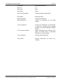
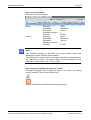
The Page Properties
Page name:
file name of the page
Background:
background color of the page
Frame:
page frame
The page frame is only visible when a page is
opened as an overlay (popup window) and the page
in the background is larger than the overlay.
Keyboard:
Here you set which "Key list" is valid on this page.
In the Key list, functions for individual keys are
defined (refer to 3.5.4)
Page is a recipe:
Here it is determined whether the page is a recipe
page, or not. If the answer is yes, then the
parameters for recipe pages are displayed (refer to
4.9).
Default path*:
Here you can enter a path where the recipe files are
to be saved. If the field remains empty, the recipes
are saved in the root directory for recipes, which is
predefined in the configuration file QViSRT.cfg.
Note:
The specifications for the "Default path" are added to the preconfigured
path with the key name "RecipeDefaultDir=" in the QViSRT.cfg of your
QViS Runtime system.
Thus, only relative paths can be entered.
Use recipe group*:
If the recipe files are to be saved in groups, this
must be checked in the Checkbox. Groups are subfiles (e.g., "LightChocolate," "DarkChocolate") in
the file system.
Auto save*:
When the option "Auto save" has been selected,
each change of a setpoint value (Read/Write
variable) is automatically saved in the recipe file. It
is not necessary to initiate storage via the "recipe
save" function.
Auto upload*:
When the option "Auto upload" is used, an upload
(i.e., the control loads the values of the Read/Write
variables) is automatically executed. It is not
QViS | Development Tool
DOC100316OI15EN | Revision 15 | English | 2012-07 | Released | Public
© Hilscher, 2010-2012
Creating a Project with QViS
23/197
necessary to initiate an upload via the "recipe
upload" function.
3.3.4
3.3.4.1
Save recipe name*:
If a recipe download is performed, Type String
saves the name of this recipe in the variables that
have been set..
Save recipe group*:
If a recipe download is performed, Type String
stores the group of this recipe in the variables that
have been set.
Width:
Page width in pixel
Height:
Page height in pixel
Element Variable
What Is the Element Variable?
The element "Variable" is used to display a variable value. It is either
displayed as a numeric value or as text (depending on the data type of the
variable).
Variable
3.3.4.2
How Do You Insert an Element Variable into QViS?
Open a page in PageEditor. In the Element List, click onto the element
"Variable":
Subsequently, you click onto the position in the page where you wish to
place the element:
QViS | Development Tool
DOC100316OI15EN | Revision 15 | English | 2012-07 | Released | Public
© Hilscher, 2010-2012
Creating a Project with QViS
24/197
Select the element in the page. The element's properties are displayed in
the Properties area. You now either choose the desired value for the
property "Variable," or double click onto the desired variable in the Feet
Tab:
select with double click
QViS | Development Tool
DOC100316OI15EN | Revision 15 | English | 2012-07 | Released | Public
© Hilscher, 2010-2012
Creating a Project with QViS
3.3.4.3
25/197
Properties of the Element Variable
Variable:
Variable, with which the element is linked.
Use bitmask:
With a bitmask, only individual bits of the variable
are taken into consideration. If a bitmask is used,
the resulting value in QViSRT is always 1 or 0.
Bitmask is only displayed when the selected
variable is an integral data type other than BOOL.
Access:
If you have set "Read/Write," the window is opened
when you click onto (or touch) the variable value in
order to allocate a new value to the variable. If the
linked variable is a STRING data type, the
alphanumeric keypad is opened, otherwise the
numeric one. When "ReadOnly" is set, nothing
happens when you click onto the variable value.
Password Level:
The Password Level is defined here. The window
for allocating a new value to the linked variable only
opens when the current User Level is greater than
or equal to the set Password Level.
QViS | Development Tool
DOC100316OI15EN | Revision 15 | English | 2012-07 | Released | Public
© Hilscher, 2010-2012
Creating a Project with QViS
26/197
Keypad position centered:
If this option has been selected, the window for
allocating a new value to the linked variable, the socalled Keypad, is opened centered to the QViS
window.
Keypad position X:
Horizontal position of the Keypad in pixel
Keypad position Y:
Vertical position of the Keypad in pixel
Auto calculate size of touchfield:
If this option has been selected, the size of the
touchfield for editing the variable is automatically
assigned.
Width of touchfield:
Width of touchfield
Height of touchfield:
Height of touchfield
Alignment:
Alignment of the character in the touchfield
Min value:
The window for allocating a new value to the
variable will not permit values lower than the limit
set here. The limit can be a fixed value or a
variable.
Max value:
The window for allocating a new value to the
variable will not permit values higher than the limit
set here. The limit can be a fixed value or a
variable.
Foreground:
text color
Background:
background color of the text
Transparent background:
If this option is selected, no background is drawn.
Character set:
The Character Set (font) set here is used in the
display format for the variable value.
Alignment:
Horizontal text alignment
Time format
In the case of a variable type "TIME," you can
select the display format (e.g., hh:mm).
Date format
In the case of a variable type "DATE," you can
select the display format (e.g., dd.mm.yy).
String length
In the case of a variable type "STRING," the length
to be displayed can be specified here.
Multiplier of variable:
For some variable types, a factor can be specified
by which the actual value is multiplied prior to
display. Attention: Currently, only factors <1 are
possible.
Pre decimal digits:
For some variable types, the maximum number of
pre decimal digits can be specified.
Post decimal digits:
For some variable types, the maximum number of
post decimal digits can be specified.
Show sign:
For some variable types, this option is selectable to
display the sign (-) in negative numbers.
QViS | Development Tool
DOC100316OI15EN | Revision 15 | English | 2012-07 | Released | Public
© Hilscher, 2010-2012
Creating a Project with QViS
27/197
Show leading zeros:
For some variable types, this option is selectable to
fill in the unneeded pre decimal digits with leading
zeros.
Lock Position:
If this option is selected, this element can no longer
be moved. This option can either be
deactivated/activated here, or via the context menu
of the element in Work Space.
Position X:
Horizontal position of the element in pixel. The
value is relative to the page (or to the object) where
the element has been added. The value 0 is the left
margin (or object margin).
Position Y:
Vertical position of the element in pixel. The value is
relative to the page (or to the object) where the
element has been added. The value 0 is the upper
margin (or object margin).
Width:
Element width in pixel. The size ensues from the
Character Set and format selected.
Height:
Element height in pixel. The size ensues from the
Character Set.
Help number:
Help number for this element
Condition Hide:
You can define a condition here. If the condition is
applicable, the element is hidden. The condition is
comprised of variable, which is compared with a
value or variable and a comparator (e.g. >=)
Condition Change Color:
You can define a condition here. If the condition is
applicable, the element will be displayed in another
color. The condition is comprised of variable, which
is compared with a value or variable and a
comparator (e.g. >=)
Condition Change Color 2:
You can define a condition here. If the condition is
applicable, the element will be displayed in another
color. The condition is comprised of variable, which
is compared with a value or variable and a
comparator (e.g. >=)
Condition Change Color 3:
You can define a condition here. If the condition is
applicable, the element will be displayed in another
color. The condition is comprised of variable, which
is compared with a value or variable and a
comparator (e.g. >=)
Condition Disable:
You can define a condition here. If the condition is
applicable, you can no longer edit the element by
clicking onto it. The condition is comprised of
variable, which is compared with a value or variable
and a comparator (e.g. >=)
QViS | Development Tool
DOC100316OI15EN | Revision 15 | English | 2012-07 | Released | Public
© Hilscher, 2010-2012
Creating a Project with QViS
3.3.5
3.3.5.1
28/197
Element Symbol
What Is the Element Symbol?
In the simplest case, it is the symbol for a specific image (image file).
During runtime, precisely this symbol is displayed. We are referring to a
static symbol.
The element "Symbol" can also be linked to a variable. The symbol then
displayed can change during runtime. Which symbol is displayed depends
on the value of the variable. You can define areas with a corresponding
symbol. If the value of the variable falls within a certain range, the
corresponding symbol is displayed. We are then referring to a dynamic
symbol.
Example: You wish to display the status of a machine as a symbol. When
the machine is running, a triangle is to be displayed, otherwise a rectangle.
For this purpose, a dynamic symbol is used. This symbol is linked to a
variable, which reflects the machine status: 1 = Run, 0 = Stop. Depending
on the variable value, the symbol displayed is either a "triangle" or a
"rectangle."
Static Symbol
3.3.5.2
Dynamic Symbol
How Do You Insert an Element Symbol into QViS?
Step 1: Inserting an element
Open a page in Page Editor. In the Element List, click onto the element
"Symbol":
Subsequently click onto the position in the page where you wish to place
the element:
QViS | Development Tool
DOC100316OI15EN | Revision 15 | English | 2012-07 | Released | Public
© Hilscher, 2010-2012
Creating a Project with QViS
29/197
Step 2: Allocating a symbol
There are two options for allocating a symbol to the element:
Step 2a Select the symbol in Properties
Select the element in the page. The element's properties are displayed in
the Properties area. Choose the desired image file for the Property
"Symbol":
QViS | Development Tool
DOC100316OI15EN | Revision 15 | English | 2012-07 | Released | Public
© Hilscher, 2010-2012
Creating a Project with QViS
30/197
Step 2b: Select the symbol in the Feet Tab
Select the element in the page and double click onto the desired symbol in
Feet Tab Symbols.
select with doubleklick
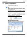
Step 3 (optional): Using a dynamic symbol
To use a dynamic symbol, you simply activate the property "Dynamic
symbol" in an existing symbol
QViS | Development Tool
DOC100316OI15EN | Revision 15 | English | 2012-07 | Released | Public
© Hilscher, 2010-2012
Creating a Project with QViS
31/197
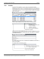
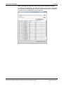
To define the areas with the corresponding symbols, click onto the button
".." at Symbols. The following window opens:
In the left-hand table, you will see the symbols available for the respective
project. When you double click onto a symbol, it is added to the table on the
right. This symbol can be allocated to a value range. If the linked variable
has a value that lies within this range, the symbol will be displayed.
When all symbols, incl. the value range, have been defined, the window
can be closed via the "OK" button.
Note:
The lower value for displaying this symbol is indicated in the column
"From," the higher one in "To."
The value range is valid, including the values indicated in the From/To
columns.
In the case of Boolean variables, you must enter the values 0/0 in
From/To for the symbol in FALSE and 1/1 for the symbol in TRUE.
Note:
For non-Boolean variables, you can define an arbitrary number of
symbols/value ranges.
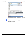
Step 3.1: Linking an element to a variable
There are two options for linking an element to a variable.
QViS | Development Tool
DOC100316OI15EN | Revision 15 | English | 2012-07 | Released | Public
© Hilscher, 2010-2012
Creating a Project with QViS
32/197
Step 3.1a: Select a variable in Properties
Select the element in the page. The element's properties are displayed in
the Properties area. Choose the desired variable for the Property
"Variable," with which this element is to be linked:
Step 3.1b: Select the variable in the Feet Tab
Select the element in the page and double click onto the desired variable in
Feet Tab Variable.
select with double click
QViS | Development Tool
DOC100316OI15EN | Revision 15 | English | 2012-07 | Released | Public
© Hilscher, 2010-2012
Creating a Project with QViS
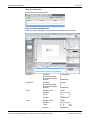
3.3.5.3
33/197
Properties of the Element Symbol
Symbol:
File name of the symbol to be displayed
Symbols:
List of symbol names and the correspondent value
range. The list can be changed by pressing the ".."
button.
Start ScaleMaker:
If symbols are used that were generated with the
ScaleMaker, to launch it, a further button, "Open
with ScaleMaker," is displayed. The ScaleMaker is
described in the chapter "Element Pointer
Instrument."
Dynamic symbol:
If "Dynamic symbol" is not activated, a certain
symbol is displayed. This symbol does not change
during runtime. Thus, this symbol is static.
If the "Dynamic symbol" is activated, the symbol
must be linked to a variable. During runtime another
symbol is displayed, depending on the value of this
variable. The parameters marked with * are only
displayed for dynamic symbols.
Variable*:
Variable to which the element is linked.
Use bitmask*:
With a bitmask, only the individual bits of the
variable are taken into consideration. If a bitmask is
used, the resulting value in QViSRT is always 1 or
0.
Bitmask is only displayed when the data type is an
integral data type other than BOOL.
Access*:
If you have set "Read/Write," the window is opened
when you click onto (or touch) the symbol in order
to add a new symbol, and thus write the linked
QViS | Development Tool
DOC100316OI15EN | Revision 15 | English | 2012-07 | Released | Public
© Hilscher, 2010-2012
Creating a Project with QViS
34/197
variable. When "ReadOnly" is set, nothing happens
when you click onto the symbol.
Password Level*:
The Password Level is defined here. The window
for selecting a new symbol only opens when the
current User Level is greater than or equal to the
set Password Level.
Keypad position centered*:
If this option has been selected, the window for
selecting a new symbol is opened centered to the
QViS window.
Keypad position X*:
Horizontal position of the window in pixel for
selecting a new symbol.
Keypad position Y*:
Vertical position of the window in pixel for selecting
a new symbol.
Transparent color:
A "transparent color" can be defined here. The pixel
with this color is not drawn.
Alignment:
Here you define the horizontal and vertical
alignment of the symbol within the element. If all
symbols have the same size, this setting is
ineffective.
Lock Position:
If this option is selected, this element can no longer
be moved. This option can either be
deactivated/activated here, or via the context menu
of the element in Work Space.
Position X:
Horizontal position of the element in pixel. The
value is relative to the page (or to the object) where
the element has been inserted. The value 0 is the
left margin (or object margin).
Position Y:
Vertical position of the element in pixel. The value is
relative to the page (or to the object) where the
element has been inserted. The value 0 is the upper
margin (or object margin).
Width:
Element width in pixel. The size automatically
ensues from the selected symbols.
Height:
Element height in pixel. The size automatically
ensues from the selected symbols.
Help number:
Help number for this element
Condition Hide:
You can define a condition here. If the condition is
applicable, the element is hidden. The condition is
comprised of variable, which is compared with a
value or variable and a comparator (e.g. >=)
Condition Disable:
You can define a condition here. If the condition is
applicable, you can no longer edit the element by
clicking onto it. The condition is comprised of
variable, which is compared with a value or variable
and a comparator (e.g. >=)
QViS | Development Tool
DOC100316OI15EN | Revision 15 | English | 2012-07 | Released | Public
© Hilscher, 2010-2012
Creating a Project with QViS
3.3.6
3.3.6.1
35/197
Element Text
What Is the Element Text?
In the simplest case, it is just a text. During runtime, precisely this text is
displayed. We are referring to a static text.
The element "Text" can also be linked to a variable. The text then displayed
can change during runtime. Which text is displayed depends on the value
of the variable. You can define areas with a corresponding text. We are
then referring to a dynamic text.
Example:
You wish to display the status of a machine as a text. When the machine is
running, "Run" is to be displayed, otherwise "Stop." For this purpose, an
element Text is used. This element is linked to a variable, which reflects the
machine status: 1 = Run, 0 = Stop. Depending on the variable value, the
either the text "Run" or "Stop" is displayed.
Static Text
3.3.6.2
Dynamic Text
How Do You Insert an Element Text into QViS?
Step 1: Inserting an element
Open a page in Page Editor. In the Element List, click onto the element
"Text":
Subsequently click onto the position in the page where you wish to place
the element:
QViS | Development Tool
DOC100316OI15EN | Revision 15 | English | 2012-07 | Released | Public
© Hilscher, 2010-2012
Creating a Project with QViS
36/197
Step 2: Allocating Text
There are two options for allocating a text to the element:
Step 2a Select the text in Properties
Select the element in the page. The element's properties are displayed in
the Properties area. Choose the desired text for the Property "Text":
QViS | Development Tool
DOC100316OI15EN | Revision 15 | English | 2012-07 | Released | Public
© Hilscher, 2010-2012
Creating a Project with QViS
37/197
Step 2b: Select the text in the Feet Tab
Select the element in the page and double click onto the desired text in
Feet Tab Texts.
select with double click
Step 3 (optional): Using a dynamic text
To use a dynamic text, you simply activate the property "Dynamic text" in
an existing text:
QViS | Development Tool
DOC100316OI15EN | Revision 15 | English | 2012-07 | Released | Public
© Hilscher, 2010-2012
Creating a Project with QViS
38/197
To define the areas with the corresponding texts, click onto the button ".." at
Texts. The following window opens:
In the left-hand table, you will see the texts available for the respective
project. When you double click onto a text, it is added to the table on the
right. This text can be allocated to a value range. If the linked variable has a
value that lies within this range, the text will be displayed.
When all texts, incl. the value range, have been defined, the window can be
closed via the "OK" button.
Note:
The lower value for displaying this text is indicated in the column "From,"
the higher one in "To."
The value range is valid, including the values indicated in the From/To
columns.
In the case of Boolean variables, you must enter the values 0/0 in
From/To for the text in FALSE and 1/1 for the text in TRUE.
Note:
For non-Boolean variables, you can define an arbitrary number of
symbols/value ranges.
Step 3.1: Linking an element with a variable
There are two options for linking an element to a variable.
QViS | Development Tool
DOC100316OI15EN | Revision 15 | English | 2012-07 | Released | Public
© Hilscher, 2010-2012
Creating a Project with QViS
39/197
Step 3.1a: Select a variable in Properties
Select the element in the page. The element's properties are displayed in
the Properties area. Choose the desired variable for the Property
"Variable," with which this element is to be linked:
Step 3.1b: Select the variable in the Feet Tab
Select the element in the page and double click onto the desired variable in
Feet Tab Variable.
select with double click
QViS | Development Tool
DOC100316OI15EN | Revision 15 | English | 2012-07 | Released | Public
© Hilscher, 2010-2012
Creating a Project with QViS
3.3.6.3
40/197
Properties of the Element Text
Text:
The text to be displayed; the text is displayed in the
language currently set for the project.
Texts:
List with the texts and the correspondent value
range. The list can be changed by pressing the ".."
button.
Dynamic text:
If "Dynamic text" is not activated, a certain text is
displayed. This text does not change during
runtime. Thus, this text is static.
If the "Dynamic text" is activated, the text must be
linked to a variable. During runtime another text is
displayed, depending on the value of this variable.
The parameters marked with * are only displayed
for dynamic text.
Variable*:
Variable to which the element is linked.
Use bitmask*:
With a bitmask, only the individual bits of the
variable are taken into consideration. If a bitmask is
used, the resulting value in QViSRT is always 1 or
0.
Bitmask is only displayed when the data type is an
integral data type other than BOOL.
Access*:
If you have set "Read/Write," the window is opened
when you click onto (or touch) the text in order to
add a new text, and thus write the linked variable.
QViS | Development Tool
DOC100316OI15EN | Revision 15 | English | 2012-07 | Released | Public
© Hilscher, 2010-2012
Creating a Project with QViS
41/197
When "ReadOnly" is set, nothing happens when
you click onto the text.
Password Level*:
The Password Level is defined here. The window
for selecting a new text only opens when the current
User Level is greater than or equal to the set
Password Level.
Keypad position centered*:
If this option has been selected, the window for
selecting a new text is opened centered to the QViS
window.
Keypad position X*:
Horizontal position of the window in pixel for
selecting a new text.
Keypad position Y*:
Vertical position of the window in pixel for selecting
a new text.
Foreground:
text color
Background:
background color of the text
Transparent background:
If this option is selected, no background will be
drawn.
Character set:
The Character Set (font) set here is used for
displaying the text.
Alignment:
Horizontal text alignment in relation to the element
width.
Lock Position:
If this option is selected, this element can no longer
be moved. This option can either be
deactivated/activated here, or via the context menu
of the element in Work Space.
Position X:
Horizontal position of the element in pixel. The
value is relative to the page (or to the object) where
the element has been inserted. The value 0 is the
left margin (or object margin).
Position Y:
Vertical position of the element in pixel. The value is
relative to the page (or to the object) where the
element has been inserted. The value 0 is the upper
margin (or object margin).
Width:
Element width in pixel. The size automatically
ensues from the selected Character Set and text
length.
Height:
Element height in pixel. The size automatically
ensues from the selected Character Set and
number of text lines.
Help number:
Help number for this element
Condition Hide:
You can define a condition here. If the condition is
applicable, the element is hidden. The condition is
comprised of variable, which is compared with a
value or variable and a comparator (e.g. >=).
QViS | Development Tool
DOC100316OI15EN | Revision 15 | English | 2012-07 | Released | Public
© Hilscher, 2010-2012
Creating a Project with QViS
42/197
Condition Change Color:
You can define a condition here. If the condition is
applicable, the element is displayed in another
color. The condition is comprised of variable, which
is compared with a value or variable and a
comparator (e.g. >=).
Condition Disable:
3.3.7
3.3.7.1
You can define a condition here. If the condition is
applicable, you can no longer edit the element by
clicking onto it. The condition is comprised of
variable, which is compared with a value or variable
and a comparator (e.g. >=)
Element Button
What Is the Element Button?
The element "Button" is a key or switch that users can activate per mouse
click or touch. This triggers a function.
Button
3.3.7.2
How Do You Insert an Element Button into QViS?
Step 1: Inserting an element
Open a page in Page Editor. In the Element List, click onto the element
"Button":
Subsequently click onto the position in the page where you wish to place
the element:
QViS | Development Tool
DOC100316OI15EN | Revision 15 | English | 2012-07 | Released | Public
© Hilscher, 2010-2012
Creating a Project with QViS
43/197
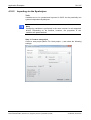
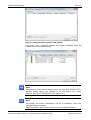
Step 2: Selecting the function to be executed
Select the element in the page. The element's properties are displayed in
the Properties area. Choose the desired button function for the Property
"Function.":
For some functions, additional parameters must be defined. The function
"change to page," e.g., an additional parameter must be defined for
stipulating the target page to be changed to.
QViS | Development Tool
DOC100316OI15EN | Revision 15 | English | 2012-07 | Released | Public
© Hilscher, 2010-2012
Creating a Project with QViS
3.3.7.3
44/197
Properties of the Element Button
Function:
Here you select the desired function for the button.
Please take note that a given hardware does not
necessarily support all functions.
Possible functions are:
"modify variable directly"
A variable can be directly modified via this function.
The following buttons are available:
"set on pressed":
Sets the variable to a defined value
when the key is pressed
"set on released":
Sets the variable to a defined value
when the key is released
"set on pressed and reset on released":
Sets the variable to a defined value
when the key is pressed, and to another
value when it is released
"set – hold – reset":
Sets the variable to a defined value
when the key is pressed for the first
time, and to another value when it is
next pressed
"increment/decrement":
Modifies the variable stepwise in the
stipulated increments and defined
interval.
At an interval value of 0, only one step
is executed.
The variable may not fall below/exceed
the preset min./max. values, and stops
when the threshold value is reached.
QViS | Development Tool
DOC100316OI15EN | Revision 15 | English | 2012-07 | Released | Public
© Hilscher, 2010-2012
Creating a Project with QViS
45/197
"increment/decrement loop":
Modifies available stepwise in the
stipulated increments and defined
interval
At an interval value of 0, only one step
is executed.
The variable may not fall below/exceed
the preset min./max. values. When the
threshold value is reached an overflow
of min. to max., or vice versa, takes
place (loop).
Note:
Only integer values can be set via the function "modify variable directly."
"edit variable as numeric"
Opens the numeric keypad for editing variables.
"edit variable as dynamic text"
Opens the Text/Symbol keypad for editing variables
as dynamic text.
"edit variable as dynamic symbol"
Opens the Text/Symbol keypad for editing variables
as dynamic symbol.
"change to page"
Closes the current page and opens another one.
"change to previous page"
Closes the current page and returns to the previous
page.
"open overlay (centered)"
Opens a page as an overlay and positions it
centered in the screen. If the overlay is larger than
the screen, it is centered in the middle of the page.
"open overlay (by position)"
Opens a page as an overlay and places it in the
stipulated position in relation to the upper left corner
of the current page.
"close overlay (return to previous)"
Closes the overlay window.
"list up"
Moves the cursor of a list up by one line.
"list down"
Moves the cursor of a list down by one line.
"list page up"
Moves the cursor of a list up by one page.
"list page down"
Moves the cursor of a list down by one page.
"list home"
Moves the cursor to the start of the list.
QViS | Development Tool
DOC100316OI15EN | Revision 15 | English | 2012-07 | Released | Public
© Hilscher, 2010-2012
Creating a Project with QViS
46/197
"list end"
Moves the cursor to the end of the list.
"list edit variable"
Edits a variable selected in the list.
"character "*""
Via the character keys, you can assign all keypad
characters to touchfield/touch keys.
"key "*""
Special keys
"change language"
Changes to the next language.
"alarm confirm"
Confirms the alarms selected in the Alarm List.
"alarm delete"
Deletes the alarm selected in the Alarm List.
"alarm confirm (all)"
Confirms all active alarms.
"alarm delete (all)"
Deletes all alarms.
"alarm history export"
Exports the alarm history to an ASCII file.
"alarm history delete entries"
Deletes the alarm history.
"contrast +/-"
Changes the display contrast.
"backlight +/-"
Changes the display backlight.
"login"
Opens the password login.
"Logout"
Sets the password level to 0 (lowest level).
"change password"
Changes the passwords. The passwords in the
system variables SYS_PASSWORD_X are taken
over as new passwords.
"recipe new (initialize with defaults)"
Initialized with the recipe editor with default values.
"recipe open"
Opens an existing recipe, displays a selection of all
available recipes.
"recipe save"
Saves the recipe under a name to be specified.
"recipe delete"
Deletes the recipe with the name selected.
"recipe upload"
Loads the values from the control into the recipe
editor.
QViS | Development Tool
DOC100316OI15EN | Revision 15 | English | 2012-07 | Released | Public
© Hilscher, 2010-2012
Creating a Project with QViS
47/197
"recipe download"
Downloads the values from the recipe editor into the
control.
"recipe open and download"
Opens an existing recipe and downloads the values
in the control.
"trend clear"
Deletes the trend buffer.
"trend setup..."
Opens the trend setup window.
"trend setup open"
Opens the selected file with the saved trend settings
and updates the respective system variables with
the values saved. The system variables
SYS_TrendSetupName und
SYS_TrendSetupGroup are set accordingly.
Only functions on the page with the trend.
"trend setup save"
Stores the current trend settings in the file whose
name is defined via SYS_TrendSetupName. The
name can be extended via SYS_TrendSetupGroup.
Only functions on the page with the trend.
"trend setup delete"
Deletes the selected files with the trend settings.
Only functions on the page with the trend.
"trend zoom in"
Extends the time axis.
"trend zoom out"
Compresses the time axis.
"trend export"
Generates an ASCII file of the logged trend.
"online help activation" / "online help deactivation"
Toggles the help mode.
"run program"
Launches another program.
"exit QViS runtime !!!"
Exits QViS, when this is supported by the
device/operating system used.
For certain functions, subsequent to their execution,
you can furthermore perform a page change.
Variable:
Here you specify the variable for button functions
that can modify a variable.
Use bitmask:
With a bitmask, only the individual bits of the
variable are taken into consideration. If a bitmask is
used, the resulting value in QViSRT is always 1 or
0.
Bitmask is only displayed when the data type is an
integral data type other than BOOL.
QViS | Development Tool
DOC100316OI15EN | Revision 15 | English | 2012-07 | Released | Public
© Hilscher, 2010-2012
Creating a Project with QViS
48/197
Password Level:
The Password Level is defined here. The button
function is only executed when the current User
Level is greater than or equal to the set Password
Level.
Type:
Here you define the appearance of the button:
Standard button:
Gray 3D button
Symbol button:
two arbitrary symbols
determine the button's appearance
Transparent button:
invisible button
"Button up" symbol:
For a symbol button, this symbol is displayed when
the button is in a "not depressed" state
"Button down" symbol: For a symbol button, this symbol is displayed when
the button is in a "depressed" state
Transparent color:
Here you can define a "transparent color." The pixel
with this color will not be drawn.
Add symbol:
With this option, a symbol can be overlayed on the
button. If the option is active, the symbol and an
(optional) transparent color can be defined.
Add text:
With this option, a text can be overlayed on the
button. If the option is active, the text, text color and
font can be defined.
Lock Position:
If this option is selected, this element can no longer
be moved. This option can either be
deactivated/activated here, or via the context menu
of the element in Work Space.
Position X:
Horizontal position of the element in pixel. The
value is relative to the page (or to the object) where
the element has been inserted. The value 0 is the
left margin (or object margin).
Position Y:
Vertical position of the element in pixel. The value is
relative to the page (or to the object) where the
element has been. inserted.
Width:
Element width in pixel. In the case of a symbol
button, the size automatically ensues from the size
of the symbol.
Height:
Element height in pixel. In the case of a symbol
button, the size automatically ensues from the size
of the symbol.
Help number:
Help number for this element
Condition Hide:
You can define a condition here. If the condition is
applicable, the element is hidden. The condition is
comprised of variable, which is compared with a
value or variable and a comparator (e.g. >=).
Condition Disable:
You can define a condition here. If the condition is
applicable, you can no longer edit the element by
clicking onto it. The condition is comprised of
variable, which is compared with a value or variable
and a comparator (e.g. >=).
QViS | Development Tool
DOC100316OI15EN | Revision 15 | English | 2012-07 | Released | Public
© Hilscher, 2010-2012
Creating a Project with QViS
3.3.8
3.3.8.1
49/197
Element Bargraph
What Is the Element Bargraph?
The element "Bargraph" is used to display a bargraph. The bargraph is
linked to a variable and changes its size accordingly.
Bargraph
Note:
An arbitrarily extended bargraph with min./max. values of 0/1, can also be
used as a color changeover for a defined surface.
QViS | Development Tool
DOC100316OI15EN | Revision 15 | English | 2012-07 | Released | Public
© Hilscher, 2010-2012
Creating a Project with QViS
3.3.8.2
50/197
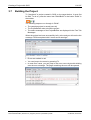
How Do You Insert and Element Bargraph into QViS?
Step 1: Inserting an element
Open a page in Page Editor. In the Element List, click onto the element
"Bargraph":
Subsequently click onto the position in the page where you wish to place
the element:
Step 2: Linking it to a Variable
There are two options for linking the element to a variable.
Step 2a: Select a Variable in Properties
Select the element in the page. The element's properties are displayed in
the Properties area. Choose the desired variable for the Property
"Variable":
QViS | Development Tool
DOC100316OI15EN | Revision 15 | English | 2012-07 | Released | Public
© Hilscher, 2010-2012
Creating a Project with QViS
51/197
Step 2b: Select the variable in the Feet Tab
Select the element in the page and double click onto the desired variable in
Feet Tab Variables.
select with double click
QViS | Development Tool
DOC100316OI15EN | Revision 15 | English | 2012-07 | Released | Public
© Hilscher, 2010-2012
Creating a Project with QViS
3.3.8.3
52/197
Properties of the Element Bargraph
Variable:
Variable to which the element is linked.
Use bitmask:
With a bitmask, only the individual bits of the
variable are taken into consideration. If a bitmask is
used, the resulting value in QViSRT is always 1 or
0.
Bitmask is only displayed when the data type is an
integral data type other than BOOL.
Min value:
The value set here corresponds to the minimum
bargraph display. This limit can be either a fixed
value or linked to a variable.
Max value:
The value set here corresponds to the maximum
bargraph display. This limit can be either a fixed
value or linked to a variable.
Direction:
Here you set the bar direction.
Foreground:
Foreground bargraph color. The foreground color
represents the process value.
Background: Background bargraph color
Transparent background:
If this option has been selected, no background
color will be drawn.
Start ScaleMaker:
Launches the ScaleMaker to draw a bitmap with a
scale. The generated scale is a BMP file, i.e., it
QViS | Development Tool
DOC100316OI15EN | Revision 15 | English | 2012-07 | Released | Public
© Hilscher, 2010-2012
Creating a Project with QViS
53/197
does not change during runtime. The ScaleMaker is
described in the chapter "Element Pointer
Instrument."
Lock Position:
If this option is selected, this element can no longer
be moved. This option can either be
deactivated/activated here, or via the context menu
of the element in Work Space.
Position X:
Horizontal position of the element in pixel. The
value is relative to the page (or to the object) where
the element has been inserted. The value 0 is the
left margin (or object margin).
Position Y:
Vertical position of the element in pixel. The value is
relative to the page (or to the object) where the
element has been inserted The value 0 is the upper
margin (or object margin).
Width:
Element width in pixel.
Height:
Element height in pixel.
Help number:
Help number for this element
Condition Hide:
You can define a condition here. If the condition is
applicable, the element is hidden. The condition is
comprised of variable, which is compared with a
value or variable and a comparator (e.g. >=).
Condition Change Color:
You can define a condition here. If the condition is
applicable, the element is displayed in another
color. The condition is comprised of variable, which
is compared with a value or variable and a
comparator (e.g. >=).
Condition Change Color 2:
You can define a condition here. If the condition is
applicable, the element is displayed in another
color. The condition is comprised of variable, which
is compared with a value or variable and a
comparator (e.g. >=).
Condition Change Color 3:
You can define a condition here. If the condition is
applicable, the element is displayed in another
color. The condition is comprised of variable, which
is compared with a value or variable and a
comparator (e.g. >=).
QViS | Development Tool
DOC100316OI15EN | Revision 15 | English | 2012-07 | Released | Public
© Hilscher, 2010-2012
Creating a Project with QViS
3.3.9
3.3.9.1
54/197
Element Arc
What Is the Element Arc?
The element "Arc" is used to display an arc. The arc is linked to a variable
and changes its size accordingly.
Arc
3.3.9.2
How Do You Insert an Element Arc into QViS?
Step 1: Inserting an element
Open a page in Page Editor. In the Element List, click onto the element
"Arc":
Subsequently click onto the position in the page where you wish to place
the element:
QViS | Development Tool
DOC100316OI15EN | Revision 15 | English | 2012-07 | Released | Public
© Hilscher, 2010-2012
Creating a Project with QViS
55/197
Step 2: Linking to a variable
There are two options for linking an element to a variable.
Step 2a: Select a variable in Properties
Select the element in the page. The element's properties are displayed in
the Properties area. Choose the desired variable for the Property
"Variable," with which this element is to be linked:
QViS | Development Tool
DOC100316OI15EN | Revision 15 | English | 2012-07 | Released | Public
© Hilscher, 2010-2012
Creating a Project with QViS
56/197
Step 2.b: Select the variable in the Feet Tab
Select the element in the page and double click onto the desired variable in
Feet Tab Variable.
select with double click
QViS | Development Tool
DOC100316OI15EN | Revision 15 | English | 2012-07 | Released | Public
© Hilscher, 2010-2012
Creating a Project with QViS
3.3.9.3
57/197
Properties of the Element Arc
Variable:
Variable to which the element is linked.
Use bitmask:
With a bitmask, only the individual bits of the
variable are taken into consideration. If a bitmask is
used, the resulting value in QViSRT is always 1 or
0.
Bitmask is only displayed when the data type is an
integral data type other than BOOL.
Min value:
The value set here corresponds to the minimum arc
graphic. This limit can be either a fixed value or
linked to a variable
Max value:
The value set here corresponds to the maximum
arc graphic. This limit can be either a fixed value or
linked to a variable.
Radius:
The radius of the arc is set here.
Arc thickness:
Arc thickness in pixel is set here.
Angle from:
The angle of the arc in degrees
Angle to:
The arc's end angle in degrees.
Direction:
Direction of the arc
Start ScaleMaker:
Launches the ScaleMaker to draw a bitmap with a
scale. The generated scale is a BMP file, i.e., it
does not change during runtime. The ScaleMaker is
QViS | Development Tool
DOC100316OI15EN | Revision 15 | English | 2012-07 | Released | Public
© Hilscher, 2010-2012
Creating a Project with QViS
58/197
described in
Instrument."
the
chapter
"Element
Foreground:
Foreground color of the arc graphic
Background:
Background color of the arc graphic
Pointer
Transparent background:
If this option has been selected, no background
color will be drawn.
Lock Position:
If this option is selected, this element can no longer
be moved. This option can either be
deactivated/activated here, or via the context menu
of the element in Work Space.
Position X:
Horizontal position of the element in pixel. The
value is relative to the page (or to the object) where
the element has been inserted. The value 0 is the
left margin (or object margin).
Position Y:
Vertical position of the element in pixel. The value is
relative to the page (or to the object) where the
element has been inserted. The value 0 is the upper
margin (or object margin).
Width:
Element width in pixel. The size automatically
ensues from the selected settings.
Height:
Element height in pixel. The size automatically
ensues from the selected settings.
Help number:
Help number for this element
Condition Hide:
You can define a condition here. If the condition is
applicable, the element is hidden. The condition is
comprised of variable, which is compared with a
value or variable and a comparator (e.g. >=)
Condition Change Color:
You can define a condition here. If the condition is
applicable, the element is displayed in another
color. The condition is comprised of variable, which
is compared with a value or variable and a
comparator (e.g. >=).
Condition Change Color 2:
You can define a condition here. If the condition is
applicable, the element is displayed in another
color. The condition is comprised of variable, which
is compared with a value or variable and a
comparator (e.g. >=).
Condition Change Color 3:
You can define a condition here. If the condition is
applicable, the element is displayed in another
color. The condition is comprised of variable, which
is compared with a value or variable and a
comparator (e.g. >=).
QViS | Development Tool
DOC100316OI15EN | Revision 15 | English | 2012-07 | Released | Public
© Hilscher, 2010-2012
Creating a Project with QViS
3.3.10
3.3.10.1
59/197
Element Pointer Instrument
What Is the Element Pointer Instrument?
The element "Pointer instrument" is used to display a pointer. The pointer is
linked to a variable and changes its angle accordingly.
Pointer
instrument
3.3.10.2
How Do You Insert an Element Pointer Instrument into QViS?
Step 1: Inserting an element
Open a page in Page Editor. In the Element List, click onto the element
"Pointer Instrument":
Subsequently click onto the position in the page where you wish to place
the element:
QViS | Development Tool
DOC100316OI15EN | Revision 15 | English | 2012-07 | Released | Public
© Hilscher, 2010-2012
Creating a Project with QViS
60/197
Step 2: Linking it to a Variable
There are two options for linking the element to a variable.
Step 2a: Select a Variable in Properties
Select the element in the page. The element's properties are displayed in
the Properties area. Choose the desired variable for the Property
"Variable":
QViS | Development Tool
DOC100316OI15EN | Revision 15 | English | 2012-07 | Released | Public
© Hilscher, 2010-2012
Creating a Project with QViS
61/197
Step 2b: Select the variable in the Feet Tab
Select the element in the page and double click onto the desired variable in
Feet Tab Variables.
select with double click
QViS | Development Tool
DOC100316OI15EN | Revision 15 | English | 2012-07 | Released | Public
© Hilscher, 2010-2012
Creating a Project with QViS
3.3.10.3
62/197
Properties of the Element Pointer Instrument
Variable:
Variable to which the element is linked.
Use bitmask:
With a bitmask, only the individual bits of the
variable are taken into consideration. If a bitmask is
used, the resulting value in QViSRT is always 1 or
0.
Bitmask is only displayed when the data type is an
integral data type other than BOOL.
Min value:
The value set here corresponds to the minimum
pointer graphic. This limit can be either a fixed value
or linked to a variable.
Max value:
The value set here corresponds to the maximum
pointer graphic. This limit can be either a fixed value
or linked to a variable
Radius:
The radius of the pointer is set here.
Angle from:
The angle of the pointer in degrees
Angle to:
The pointer's end angle in degrees.
Direction:
Direction of the pointer
Start ScaleMaker
Launches the ScaleMaker to draw a bitmap with a
scale. The generated scale is a BMP file, i.e., it
does not change during runtime. The ScaleMaker is
described in the following chapter "Element Pointer
Instrument."
QViS | Development Tool
DOC100316OI15EN | Revision 15 | English | 2012-07 | Released | Public
© Hilscher, 2010-2012
Creating a Project with QViS
63/197
Color of pointer:
Color of the pointer
Style:
Pointer style "Simple" is a simple pointer,
"User defined": You can specify the pointer's form,
yourself
Pointer points:
The pointer is a polygon. The pointer's corner points
can be defined here. The unit for x and y
coordinates is percent (100% corresponds to the
radius).
Lock Position:
If this option is selected, this element can no longer
be moved. This option can either be
deactivated/activated here, or via the context menu
of the element in Work Space.
Position X:
Horizontal position of the element in pixel. The
value is relative to the page (or to the object) where
the element has been inserted. The value 0 is the
left margin (or object margin).
Position Y:
Vertical position of the element in pixel. The value is
relative to the page (or to the object) where the
element has been inserted. The value 0 is the upper
margin (or object margin).
Width:
Element width in pixel. The size automatically
ensues from the selected settings.
Height:
Element height in pixel. The size automatically
ensues from the selected settings.
Help number:
Help number for this element
Condition Hide:
You can define a condition here. If the condition is
applicable, the element is hidden. The condition is
comprised of variable, which is compared with a
value or variable and a comparator (e.g. >=)
Condition Change Color:
You can define a condition here. If the condition is
applicable, the element is displayed in another
color. The condition is comprised of variable, which
is compared with a value or variable and a
comparator (e.g. >=).
Condition Change Color 2:
You can define a condition here. If the condition is
applicable, the element is displayed in another
color. The condition is comprised of variable, which
is compared with a value or variable and a
comparator (e.g. >=).
Condition Change Color 3:
You can define a condition here. If the condition is
applicable, the element is displayed in another
color. The condition is comprised of variable, which
is compared with a value or variable and a
comparator (e.g. >=).
QViS | Development Tool
DOC100316OI15EN | Revision 15 | English | 2012-07 | Released | Public
© Hilscher, 2010-2012
Creating a Project with QViS
3.3.10.4
64/197
Creating a Scale Using the ScaleMaker
Using the ScaleMaker, you can draw a simple scale. This scale is saved as
a bitmap file (.sm.bmp) and can be used in QViS:
Scale type:
Scale type "Round" or "Straight"
In the case of scale type "Round":
Radius:
Inner radius in pixel
Angle from:
Start angle in degrees
Angle to:
End angle in degrees
Direction:
Direction of the scale
Arc color:
Color of the scale line (arc line)
Background color:
Background color of the scale
In the case of scale type "Straight":
Bargraph width:
Bargraph width
Bargraph height:
Bargraph height
Direction:
Direction of the bargraph
QViS | Development Tool
DOC100316OI15EN | Revision 15 | English | 2012-07 | Released | Public
© Hilscher, 2010-2012
Creating a Project with QViS
3.3.11
3.3.11.1
65/197
Foreground color:
Color of the scale line (long line)
Background:
Background color of the scale
Swap position:
Reverse the scale's position (up<->down, left <->
right)
Line length:
Line length in pixel
Line color:
Line color
Count of segments:
Number of segments
Show text:
Activate or deactivate text
Text color:
Text color
Font size:
Font size
Text distance:
Distance of text to scale
Min/Max value:
Minimum and maximum values; these are used to
generate texts
Spaces:
Margin distances in pixel
Element Vector Graphic
What Is the Element Vector Graphic?
The element "Vector graphic" is used to create and display simple vector
graphics directly in QViS.
Yellow frame as
vector grafic
QViS | Development Tool
DOC100316OI15EN | Revision 15 | English | 2012-07 | Released | Public
© Hilscher, 2010-2012
Creating a Project with QViS
3.3.11.2
66/197
How Do You Insert an Element Vector Graphic into QViS?
Step 1: Inserting an element
Open a page in Page Editor. In the Element List, click onto the element
"vector graphic":
Subsequently click onto the position in the page where you wish to place
the element. The Graphic Editor will open instead of the Page Editor:
Step 2: Creating a vector graphic using the Graphic Editor
The view changes and the Graphic Editor comes to the foreground.
In the Graphic Editor, you can only create rectangles, ellipses, lines and
free-hand drawings and modify their properties:
QViS | Development Tool
DOC100316OI15EN | Revision 15 | English | 2012-07 | Released | Public
© Hilscher, 2010-2012
Creating a Project with QViS
67/197
The editor has command over the following five basic elements:
Rectangle
To display rectangles of any type and size.
Ellipse
To display ellipses and circles of any type and size.
Line
To display lines of any position and length.
Pencil
To display free-hand drawings of any type and
shape/form.
Path
To display arbitrary "angular" interrelated lines and
polygons.
In the Properties, the position, line thickness and if needed, fill color, are
freely selectable for each drawn element.
To display overlaps as desired, each drawn element is allocated to a layer.
The layers are viewable and shiftable in the layer overview in order. The
position of the layer can be modified via the context menu.
In the layer view, the background image intensity can be adjusted to make
proportions and positions of the elements visible on the current page, which
provides for orientation.
Step 3: Exiting the graphic editor
You can exit the editor via "Save and Exit" or "Abort," whereby the changes
are only taken over by "Save and Exit."
After exiting the graphic editor, you are returned to View Page.
QViS | Development Tool
DOC100316OI15EN | Revision 15 | English | 2012-07 | Released | Public
© Hilscher, 2010-2012
Creating a Project with QViS
68/197
The selected element "Vector graphic" has, as do all other elements, a set
of properties, which can be edited via "Properties."
3.3.11.3
Properties of the Element Vector Graphic
Lock Position:
If this option is selected, this element can no longer
be moved. This option can either be
deactivated/activated here, or via the context menu
of the element in Work Space.
Position X:
Horizontal position of the element in pixel. The
value is relative to the page (or to the object) where
the element has been inserted. The value 0 is the
left margin (or object margin).
Position Y:
Vertical position of the element in pixel. The value is
relative to the page (or to the object) where the
element has been inserted. The value 0 is the upper
margin (or object margin).
Width:
Element width in pixel. In the case of a symbol
button, the size automatically ensues from the
symbol's size.
Height:
Element height in pixel. In the case of a symbol
button, the size automatically ensues from the
symbol's size.
QViS | Development Tool
DOC100316OI15EN | Revision 15 | English | 2012-07 | Released | Public
© Hilscher, 2010-2012
Creating a Project with QViS
3.3.12
3.3.12.1
69/197
Help number:
Help number for this element
Condition Hide:
You can define a condition here. If the condition is
applicable, the element is hidden. The condition is
comprised of variable, which is compared with a
value or variable and a comparator (e.g. >=)
Condition Disable:
You can define a condition here. If the condition is
applicable, you can no longer edit the element by
clicking onto it. The condition is comprised of
variable, which is compared with a value or variable
and a comparator (e.g. >=)
Element List
What Is the Element List?
The element "List" is used to display the following:
•
A list of numerous variable values
•
An Alarm or Alarm History list
•
A list needed for creating an input window
Alarm list
3.3.12.2
Variable list
How Do You Insert an Element List into QViS?
Step 1: Inserting an element
Open a page in Page Editor. In the Element List, click onto the element
"List":
Subsequently click onto the position in the page where you wish to place
the element:
QViS | Development Tool
DOC100316OI15EN | Revision 15 | English | 2012-07 | Released | Public
© Hilscher, 2010-2012
Creating a Project with QViS
70/197
Step 2: Specifying List Types and Columns
Select the element on the page. The element's properties are displayed in
the Properties area. Choose the list type, activate the desired columns and
define the position of the individual columns.
You can find detailed examples of lists in the chapter "Application
Examples."
3.3.12.3
Properties of the Element List
QViS | Development Tool
DOC100316OI15EN | Revision 15 | English | 2012-07 | Released | Public
© Hilscher, 2010-2012
Creating a Project with QViS
Type:
71/197
You define the list type here:
Variable list:
This is a list containing numerous variable values.
This list is used, e.g., when many variable values
are to be displayed.
Alarm list:
In an alarm list, the active alarms and their
respective status can be displayed.
Alarm history list:
In an alarm history list, the times when alarms were
active can be displayed.
Input list:
This list is needed when an input mask for dynamic
symbols or texts are to be created.
Variables:
These variables are listed in the variable list.
No unit conversion:
If this option has been selected, the values of the
variables are not converted to their set units.
Alarm classes:
Only alarms of this alarm class are displayed in the
alarm list.
Show seconds in list:
If this option has been selected, the times, including
seconds, are displayed in the column "Timestamp."
Automatically scroll list:
If this option has been selected, the alarm list is
periodically further scrolled.
Note:
Please ensure that the cursor is activated and no element for operating
the list is available on the page.
Automatically activate help:
The help mode for the alarm list is always active
and by clicking onto the alarm list, the online help
for the selected alarm is unhidden.
Note:
The online help is only displayed for the marked variable when it has also
been assigned a help number.
Cursor:
Disable:
The list has no cursor.
Enable:
The cursor of the list is always
activated.
Toggle:
The cursor can be activated and
deactivated
via a mouse click or by touch.
Line number:
Sequential number per line.
Variable description:
Description text from the variable declaration.
QViS | Development Tool
DOC100316OI15EN | Revision 15 | English | 2012-07 | Released | Public
© Hilscher, 2010-2012
Creating a Project with QViS
72/197
Value:
Variable value
Unit:
Description text of the unit of the variable.
Min, Max value:
The limits of the variable declaration.
Default:
The default value of the variable declaration.
Timestamp:
Timestamp with date and time (optionally with
seconds)
Alarm description:
Description text from the variable declaration.
Alarm class description:
Description text from the alarm class.
Variable:
Variable value when the alarm occurs. Any alarm
variable can store the value of a variable. This
variable is set in the variable declaration of the
alarm variable (Variable to store).
Date:
Date
Time:
Time (optionally with seconds)
Note:
The information field "Timestamp" contains the same declarations as in
the mutual use of the information fields "Date" and "Time."
Character set:
The Character Set (font) set here is used here is for
displaying the texts.
Line gap:
Distance between the individual lines in pixel.
Fore-/Background:
Text
color
Alarms in the alarm lists are displayed in the color
of their alarm class (refer to Project Properties,
Alarms)
Background:
Background color of the list
Access:
The list content can only be edited when
Read/Write is set here.
Password Level:
The Password Level is defined here. The list
content can only be when the current User Level is
greater than or equal to the set Password Level.
Lock Position:
If this option is selected, this element can no longer
be moved. This option can either be
deactivated/activated here, or via the context menu
of the element in Work Space.
Position X:
Horizontal position of the element in pixel. The
value is relative to the page (or to the object) where
the element has been inserted. The value 0 is the
left margin (or object margin).
Position Y:
Vertical position of the element in pixel. The value is
relative to the page (or to the object) where the
element has been inserted. The value 0 is the upper
margin (or object margin).
QViS | Development Tool
DOC100316OI15EN | Revision 15 | English | 2012-07 | Released | Public
© Hilscher, 2010-2012
Creating a Project with QViS
73/197
Width:
Element width in pixel.
Height:
Element height in pixel.
Help number:
Help number for this element
Condition Hide:
You can define a condition here. If the condition is
applicable, the element is hidden. The condition is
comprised of variable, which is compared with a
value or variable and a comparator (e.g. >=)
Condition Change Color:
You can define a condition here. If the condition is
applicable, the element will be displayed in another
color. The condition is comprised of variable, which
is compared with a value or variable and a
comparator (e.g. >=)
3.3.13
3.3.13.1
Element Trend
What Is the Element Trend?
The element "Trend" is used to graphically display the trend of the variable
values.
Trend
Note:
A Trend can display a maximum of eight variables.
Only one "Trend" element can be created per page.
A maximum of four Trends per project, distributed over four pages, can be
used.
3.3.13.2
How Do You Insert an Element Trend into QViS?
The Trend functionality can be deactivated for the existing device. If the
trend functionality is deactivated, no Trend element can be inserted.
Step 1: Inserting an element
Open a page in Page Editor. In the Element List, click onto the element
"Trend":
QViS | Development Tool
DOC100316OI15EN | Revision 15 | English | 2012-07 | Released | Public
© Hilscher, 2010-2012
Creating a Project with QViS
74/197
Subsequently click onto the position in the page where you wish to place
the element:
Step 2: Defining Properties
Select the element in the page. The element's properties are displayed in
the Properties area. Choose which variables can be logged, define the
colors and size of the Trend.
You can find detailed examples of lists in the chapter "Application
Examples."
3.3.13.3
Properties of the Element Trend
QViS | Development Tool
DOC100316OI15EN | Revision 15 | English | 2012-07 | Released | Public
© Hilscher, 2010-2012
Creating a Project with QViS
75/197
Variables:
The possible variables which can be configured for
logging are selected here.
Buffer size [kB]:
Buffer size
Auto delete trend data, when config changes:
If this option has been selected, configuration
changes of the logged data are automatically
deleted to activate the changes. Logging can then
be launched.
Use groups for config: Trend configurations can be merged to groups. This
function is activated via this setting.
Configuration path:
Directory under which the trend configurations are
to be saved.
Enable auto save:
When this option is activated, the logged data are
saved in a file. If such a file exists when QViSRT is
launched, the content is loaded and displayed in the
Trend window.
Horizontal areas for list page up/down:
Number of horizontal areas. Via the function "list
page up/down,” the cursor jumps one are farther.
Export filename:
The function "trend export" can be called up via a
button. Should this take place, a tabulatorseparated ASCII file is saved under the specified
name, which can be further processed by any
common text editor at a later date.
Text color:
Text color for the texts (legend, values)
Background:
Background color of the element
Color line 1 – 8:
Color of the lines
Position of description: Position of the legend display on the lower margin
or on the right side
Column width:
Width of the legend display, should it be located on
the right margin
Character set:
Character set (font) for texts
Date format:
Display format for the date
Lock Position:
If this option is selected, this element can no longer
be moved. This option can either be
deactivated/activated here, or via the context menu
of the element in Work Space.
Position X:
Horizontal position of the element in pixel. The
value is relative to the page (or to the object) where
the element has been inserted. The value 0 is the
left margin (or object margin).
Position Y:
Vertical position of the element in pixel. The value is
relative to the page (or to the object) where the
element has been added. The value 0 is the upper
margin (or object margin).
Width:
Element width in pixel.
Height:
Element height in pixel.
QViS | Development Tool
DOC100316OI15EN | Revision 15 | English | 2012-07 | Released | Public
© Hilscher, 2010-2012
Creating a Project with QViS
3.3.14
3.3.14.1
76/197
The Object
What Is an Object?
An object is a group of several elements. An object can be inserted into a
page:
Could be an object
3.3.14.2
How Do You Insert an Object into QViS?
Step 1a: Inserting a new object
Open a page in Page Editor. In the Element List, click onto the button
"Insert a new object" in the Element list:
Subsequently click onto the position in the page where you wish to place
the element. You can also keep the mouse depressed and "pull" a frame to
define the object's size:
QViS | Development Tool
DOC100316OI15EN | Revision 15 | English | 2012-07 | Released | Public
© Hilscher, 2010-2012
Creating a Project with QViS
77/197
Step 1b:Inserting an existing object
Should you wish to insert an existing object in a page, click onto the button
"Insert a new object" in the Element list:
Subsequently click onto the position in the page where you wish to
place the element. Select the object and for assigning, choose an
object in Properties:
3.3.14.3
Properties of an Object:
Name:
The object name is displayed here, and another
object can be selected.
Background:
Background color of the object
QViS | Development Tool
DOC100316OI15EN | Revision 15 | English | 2012-07 | Released | Public
© Hilscher, 2010-2012
Creating a Project with QViS
78/197
Transparent background:
If this option is selected, no background will be
drawn.
3.3.14.4
Position X:
Horizontal position of the object in pixel. The value
is relative to the page where the object has been
inserted. The value 0 is the left margin.
Position Y:
Vertical position of the object in pixel. The value is
relative to the page where the object has been
inserted. The value 0 is the upper margin.
Width:
Object width in pixel.
Height:
Object height in pixel.
Help number:
Help number for this object
Condition Hide:
You can define a condition here. If the condition is
applicable, the object is hidden. The condition is
comprised of variable, which is compared with a
value or variable and a comparator (e.g. >=).
Condition Move:
Here you can link the object to two variables. During
runtime, the object will be drawn with an offset
determined by the values of these variables. The
unit is pixel.
How Do You Edit an Object?
An object is edited in Object Editor. There are two options for opening an
object in Object Editor:
•
On a page:
If an object has been inserted on a page, the object can be directly
edited in this page. To do so, open the page via Page Editor and
then double-click onto the object:
QViS | Development Tool
DOC100316OI15EN | Revision 15 | English | 2012-07 | Released | Public
© Hilscher, 2010-2012
Creating a Project with QViS
•
79/197
Only the object, itself:
The object is opened by double-clicking onto the object in the Feet
Tab "Objects":
The same elements can be added to an object, as to a page. Operating the
Object Editor is also the same as for Page Editor.
3.3.14.5
Object Instances
If an object is used numerous times, specific properties may vary in each
object instance. The case of an object that is used numerous times having
different properties could either be desired, or not. The following two use
cases are possible:
Object:
Application Case A: The same temperature is to be displayed on each
page.
Temperature 1
QViS | Development Tool
DOC100316OI15EN | Revision 15 | English | 2012-07 | Released | Public
© Hilscher, 2010-2012
Creating a Project with QViS
80/197
Temperature 1
Application Case B: A different temperature is to be displayed on each
page.
Temperature Min.
Temperature Max.
If an object is used numerous times, for some properties the additional
option "use local settings" is displayed:
If you do not select "use local settings," the following properties (indented
properties) are global, i.e., these properties are unique and any changes to
them will affect all object instances, where likewise "use local settings" was
not selected. In our example, that would be Application Case A.
If you select "use local settings," the following properties (indented
properties) are only locally valid (only for this object instance). Changing
local settings will not affect other object instances. In our example, that
QViS | Development Tool
DOC100316OI15EN | Revision 15 | English | 2012-07 | Released | Public
© Hilscher, 2010-2012
Creating a Project with QViS
81/197
would be Application Case B and the settings are "use local,
Variable=TempMin" and "use local, Variable=TempMax."
3.4
The Feet Tabs
In the lower area, you will see five registers (tabs), called "Feet Tabs":
Feed Tabs:
3.4.1
Messages
The messages are used for:
•
Results for Find and Replace.
QViS | Development Tool
DOC100316OI15EN | Revision 15 | English | 2012-07 | Released | Public
© Hilscher, 2010-2012
Creating a Project with QViS
•
3.4.2
82/197
Output texts for building the project (Build)
Symbols
In the Feet Tab "Symbols," you can view and delete the symbols (image
files) contained in the project. Furthermore, new symbols can be added to
the project.
Note:
Bitmap types BMP are supported.
The symbols can be stored in sub-files. However, on the hard disk, all
symbols are stored in the same directory. The sub-files in QViS are only
virtual files.
In the file "All symbols", all symbols are comprised that were added to the
current project.
All symbols provided with QViS are located in the file "QViS Symbols." By
double-clicking onto a symbol in the Symbol Library (or via a right click and
"add to project"), the symbol is copied and added to the project.
QViS | Development Tool
DOC100316OI15EN | Revision 15 | English | 2012-07 | Released | Public
© Hilscher, 2010-2012
Creating a Project with QViS
83/197
The toolbar offers the following options:
Current symbol path
Move up by one file
Add selected symbol to project
Create a new file
Add a symbol
Example: Add an image file to the project
Click onto the button "Add symbol" in the Feet Tab "Symbols":
Subsequently, a dialogue is opened for selecting one or more image files
(.BMP). The selected files are copied into the project file, if it does not yet
exist here.
3.4.3
Texts
In the Feet Tab Texts, you can create, view and edit texts.
Note:
Line breaks are not automatic. However, via "/n" you can force one at any
given place.
Texts are stored in lists. The standard text list is the text list DefaultText.qtx.
This list is automatically generated and opened when a new project is
created. You can recognize an open text list, amongst others, by the path:
QViS | Development Tool
DOC100316OI15EN | Revision 15 | English | 2012-07 | Released | Public
© Hilscher, 2010-2012
Creating a Project with QViS
84/197
Within an open text list, the toolbar offers the following options:
Opened text list
Exit the open text list
Add a new language column
Create a new text
Note:
Creating the list, adding a further language or having a list translated by
external personnel is possible with the aid of an Excel table (see 4.4.2).
When you exit an open text list and thus close the text, you see a list
displaying the existing text list and a list entitled "All texts," containing all
texts:
By double-clicking onto a list, it is opened. No texts can be added to the list
"All texts."
The toolbar offers the following options:
No text list opened
Has no function here
Add an existing text list
Create a new text list
QViS | Development Tool
DOC100316OI15EN | Revision 15 | English | 2012-07 | Released | Public
© Hilscher, 2010-2012
Creating a Project with QViS
3.4.4
85/197
Variables
In the Feet Tab "Variables," you can create, view and edit variables.
Variables are stored in lists. The standard variable list is the variable list
DefaultVariables.qva. This list is automatically generated and opened when
a new project is created. You can recognize an open variable list, amongst
others, by the path:
Within an open variable list, the toolbar offers the following options:
Shows defaults to the value
range and display
Opened variable list
Exit the open variable list
Create a new variable
When you exit an open variable list and thus close the variable list, you see
a list displaying the existing variable lists and a list entitled "All variables,"
containing all variables:
By double-clicking onto a list, it is opened. No variables can be added to
the list "All variables."
The toolbar offers the following options:
No variable list opened here
Has no function here
Add an existing variable list
Create a new variable list
QViS | Development Tool
DOC100316OI15EN | Revision 15 | English | 2012-07 | Released | Public
© Hilscher, 2010-2012
Creating a Project with QViS
3.4.4.1
86/197
Properties of a Variable
Name:
Name of the variable, the variable is referenced in
other places in QViS on the basis of this name
Data type:
Data type, supported data types:
BIT
INT8, UINT8,
INT16, UINT16,
INT32, UINT32,
REAL,
STRING
TIME (UINT32 with the number of milliseconds
since
00:00)
DATE (UINT32 with the number of seconds since
1.1.1970)
Read/Write:
In the case of Read/Write variables, a specific
keypad is opened so that the variable can be
written. In ReadOnly variable, this is not the case.
Flags:
Here you can declare a variable to be "Standard,"
"Alarm" or "Local."
Standard: Variables in the process that are
exclusively used for input and output.
Alarm:
Variables in the process that are
continuously read may trigger an event when
changed to a non-zero value, which can lead to
entries in the alarm list and alarm history list.
Local:
Variable for purely internal use of
QViSRT.
Note:
Local variables are stored in a file and are read in from there when
QViSRT is rebooted.
Local variables therefore require an address allocation that, as of QViS
V3, can only be set via the simulation address.
Pay heed that each local variable is allocated its own simulation address.
The next free simulation address is dependent upon the length of the
previous data type.
Note:
Local variables can be used, e.g., to display values on a different page
than the one where a user entered them.
When storing recipes, e.g., it is thus possible to store a freely editable test
with the recipe.
Alarm class:
The alarm class for alarm variables are set here.
Each alarm variable belongs to a class.
Variable to store:
For alarm variables, you can (optional setting) enter
a variable here. If the alarm is active, the value of
QViS | Development Tool
DOC100316OI15EN | Revision 15 | English | 2012-07 | Released | Public
© Hilscher, 2010-2012
Creating a Project with QViS
87/197
this variable is logged and can be displayed in the
alarm
list
(e.g.:
For
the
alarm
"TemperatureTooHigh,"
the
value
for
"Temperature" should also be logged.
Help number:
A help number can be assigned to an alarm.
Description:
Optional description text, is used at certain places
(e.g., element Variable List).
Unit:
Unit as a description text, when "Use base unit" is
selected, you can select a unit group (Unit group 00
- 31)
Simulation:
You can enter simulation values here. Note:
Simulating values does not function for all
communication drivers.
Multiplier:
During runtime, the value of the variable set here is
multiplied with the set Multiplier ("scaled"). If the
Multiplier is 1, the value remains unchanged. If the
Multiplier value is 0.1, the variable value is
multiplied with 0.1. Not every value is allowed to be
a
Multiplier, e.g., the value may not exceed 1. Typical
values are 0.1 0-01, 0.001, etc.
Min value:
The minimum value is used for the keypad. An input
falling below this value is prevented. The value can
either be fixed or linked to a variable.
Max value:
The maximum value is used for the keypad. An
input exceeding this value is prevented. The value
can either be fixed or linked to a variable.
Default value:
The default value can be used by certain functions,
e.g. the function "set to default". QViS does not
initialize the variable (!) with this value.
QViS | Development Tool
DOC100316OI15EN | Revision 15 | English | 2012-07 | Released | Public
© Hilscher, 2010-2012
Creating a Project with QViS
3.4.4.2
88/197
Systems Variables
Certain variables are already reserved by QViS. They are set by QViS
(e.g., the current page number is saved as a variable) or must be correctly
used for certain functions (e.g., to change the date, a specific system
variable is written).
These variables are called systems variables and are declared in the file
"System.qva". When a new project is created, the variable list System.qva
is automatically generated. Each variable serves a specific purpose:
Name
Description
Type
SYS_ActualDate
Current date
Read/Write
SYS_ActualTime
Current time
Read/Write
SYS_AlarmHistExportPath
Path prefix for Alarm History export Read/Write
directory, when specified, this declaration
is attached to the registration value
"ExportDir"
(refer
to
QViSRT
Documentation).
SYS_AlarmHistExportState
Status of the Alarm History export (1 .. ReadOnly
process concluded error-free, 0 .. process
is currently being executed, -xxx ..
systems error number)
SYS_Alarms
Number of active alarms
ReadOnly
SYS_AlwaysFalse
Always 0
ReadOnly
SYS_AlwaysTrue
Always 1
ReadOnly
SYS_AutoLogoutMinutes
Time interval for automatic log-out, 0 .. no Read/Write
automatic logging out
X
SYS_BeeperState
Beeper settings (0 = no beeper, 1 = Read/Write
Beeper for touch function; only functions
on special hardware)
X
SYS_Brightness
Brightness (only functions on special Read/Write*
hardware)
X
SYS_ChangePageDuration
Time in milliseconds needed for the last ReadOnly
page change. The time is clocked from the
time of input until page display is
concluded.
SYS_Contrast
Contrast (only
hardware)
SYS_CpuLoad
CPU load (0..100%, -1 means "unknown")
SYS_DataTransferState
Status display of whether
currently being read or written
functions
0..data ready; 1..busy
2..busy data writing
on
data
special Read/Write*
data
Retain
X
X
ReadOnly
are ReadOnly
reading;
Is only used by the QClientOPC for recipe
QViS | Development Tool
DOC100316OI15EN | Revision 15 | English | 2012-07 | Released | Public
© Hilscher, 2010-2012
Creating a Project with QViS
89/197
upload and recipe download
SYS_HelpContext
Help context (is set on the projected value Read/Write
of the selected element when Help is
called up)
If dynamic texts are defined for this
variable, in this configuration an external
help program is provided as a parameter
when the external program is called up
(e.g.: links for a browser can be defined
here)
SYS_HelpMode
Help mode (0..Normal, 1..Help mode Read/Write
active)
SYS_HwBrightness
Internal (only
hardware)
functions
on
special ReadOnly
SYS_HwContrast
Internal (only
hardware
functions
on
special ReadOnly
SYS_InputValueMax
Maximum input value
ReadOnly
SYS_InputValueMin
Minimum input value
ReadOnly
SYS_InputValueNew
Input value
ReadOnly
SYS_InputValueSaved
Old input value
ReadOnly
SYS_InputVarName
Description text (Description) of current ReadOnly
input variable
SYS_InputVarUnit
Unit of the current input variable
ReadOnly
SYS_Language_01_Enable Enables locking (0) or activation (1)
SYS_Language_32_Enable languages
Only possible for languages existing in the
project (refer to Project Properties,
Languages).
Read/Write
X
SYS_LanguageNr
Language number (changing this variable Read/Write
triggers a change in languages)
X
SYS_LoginLevel
Current Password Level
SYS_NetworkDHCP
DHCP-Enable
active)
SYS_NetworkIpAddress
Network IP address
SYS_NetworkPassword
Network password; is only used for Read/Write
printing
SYS_NetworkStdGateway
Network Standard Gateway
ReadOnly
SYS_NetworkSubNetMask
Network subnet mask
ReadOnly
SYS_NetworkUser
Network user name; is only used for Read/Write
printing (only functions on special
hardware)
(0..inactive,
QViS | Development Tool
DOC100316OI15EN | Revision 15 | English | 2012-07 | Released | Public
ReadOnly
1..DHCP ReadOnly
ReadOnly
X
X
© Hilscher, 2010-2012
Creating a Project with QViS
90/197
SYS_NewPassword
- (only functions on special hardware)
Read/Write
SYS_OperatingSystem
Operating system as a number
0=unknown
1=Windows on PC e.g., Windows XP
2=Windows CE
3=Linux
4=rcX
ReadOnly
SYS_PageNrOverlay
Page number of the opened overlay (-1 = ReadOnly
no overlay opened)
SYS_PageNr
Image number of the opened page Read/Write
(changing this variable triggers a page
change)
SYS_Password_0
Password from Level 0 to Password of ReadOnly
Level 9
X
SYS_PrnColor
0..b/w
printer,
1..color
printer Read/Write
(only functions on special hardware)
X
SYS_PrnOrientation
Paper orientation (0..portrait, 1..landscape) Read/Write
(only functions on special hardware)
X
SYS_PrnOutputPath
Printer path (e.g. "COM3: 115200" or Read/Write
\\server-name\printer-name)
(only
functions on special hardware)
X
SYS_PrnPaperSize
Paper format (1..letter, 5..legal, 9..A4, Read/Write
12..B4, 13..B5) (only functions on special
hardware))
X
SYS_PrnPrepareState
Print preparation status when printing from ReadOnly
the PLC (0..ready, 1..print preparation
active) (only functions on special
hardware)
SYS_PrnQuality
0..draft, 1..high (only functions on special Read/Write
hardware)
SYS_PrnState
Printer status (0..printer inactive, 1..active)
SYS_QViSProjectAuthor
Author from the project description (is ReadOnly
transferred as an ASCII string, 4
characters long)
SYS_QViSProjectDate
Date, when the project was built (is ReadOnly
automatically generated)
SYS_QViSProjectDescripti
on
Description from the project description (is ReadOnly
transfered as an ASCII string, 28
characters long)
SYS_QViSProjectRelease
Release Number (2 for 1.2.3) of the project ReadOnly
builder, with which the project was built
SYS_QViSProjectRevision
Revision Number (3 for 1.2.3) of the ReadOnly
project builder, with which the project was
built
QViS | Development Tool
DOC100316OI15EN | Revision 15 | English | 2012-07 | Released | Public
X
ReadOnly
© Hilscher, 2010-2012
Creating a Project with QViS
91/197
SYS_QViSProjectTime
Time when the project was built (is ReadOnly
automatically generated)
SYS_QViSProjectVersion
Version Number (1 für 1.2.3) of the project ReadOnly
builder, with which the project was built
SYS_QViSRelease
QViS Release Number (2 für 1.2.3) of the ReadOnly
runtime system
SYS_QViSRevision
QViS Revision Number (3 für 1.2.3) of the ReadOnly
runtime system
SYS_QViSVersion
QViS Version Number (1 für 1.2.3) of the ReadOnly
runtime system
SYS_RandomValue
Random value (is needed, e.g., for ReadOnly
Password Level 9). This random value
changes in the same time interval as the
validity of Password Level 9 (duration of
validity).
SYS_RecipeDate
SYS_RecipeGroupLastDownloaded
Group name of the last recipe loaded in ReadOnly
the machine
SYS_RecipeGroup
Group name of the open recipe
Read/Write
SYS_RecipeName
File name of the open recipe
Read/Write
SYS_RecipeNameLastDownloaded
File name of the last recipe loaded in the ReadOnly
machine
X
SYS_RecipePath
Path prefix for the recipe path
X
SYS_RecipeState
Status of opening or storing recipes (1 .. ReadOnly
process concluded error-free, 0 .. process
is currently being executed, -xxx ..
systems error number)
SYS_RecipeTime
Time of the opened recipe
SYS_RemoteState
Remote operation (0..local, 1..remote) Read/Write
(only functions on special hardware)
SYS_ScreenOffMinutes
Time interval for screen off. (only functions Read/Write
on special hardware under Windows CE)
SYS_ServerEnable
PLC server (1), PLC client (0) (only ReadOnly
functions on special hardware)
SYS_ShiftStatus
State of the shift key (1..shift active, 0..not Read/Write
active)
SYS_SystemStatus
QViS Status (1 = OK, currently the same ReadOnly
value = 1)
SYS_SystemVersion
Operating system/Firmware Description of ReadOnly
version (string, string length: 32)
SYS_Temperature
Temperature of the display (only functions ReadOnly
QViS | Development Tool
DOC100316OI15EN | Revision 15 | English | 2012-07 | Released | Public
Read/Write
X
ReadOnly
X
© Hilscher, 2010-2012
Creating a Project with QViS
92/197
on special hardware)
SYS_TrendExportPath
Path prefix for Trend export directory, Read/Write
when specified, this input is attached to
the registration value "ExportDir" (refer to
QViSRT Documentation).
X
SYS_TrendExportState
Status of the trend data export (1 .. ReadOnly
process concluded error-free, 0 .. process
is currently being executed, -xxx ..
systems error number
SYS_TrendInterval_1-8
Logging interval for
1..0.5s, 2..1s, 3..5s,
6..30min, 7..1h)
SYS_TrendMax_1-8
Maximum value
Read/Write
SYS_TrendMax_9-12
Maximum value (only for line diagrams)
Read/Write
SYS_TrendMaxDisp_1-8
y value for the maximum value in percent Read/Write
of the Trend window height (from below)
SYS_TrendMaxDisp_9-12
y value for the maximum value in percent Read/Write
of the line diagram window height (from
below)
SYS_TrendMin_1-8
Minimum value
Read/Write
SYS_TrendMin_9-12
Minimum value (only for line diagrams
Read/Write
SYS_TrendMinDisp_1-8
y value for the minimum value in percent Read/Write
of the Trend window height (from below)
SYS_TrendMinDisp_9-12
y value for the minimum value in percent Read/Write
of the line diagram window height (from
below)
SYS_TrendSetupGroup
Group for setting up or storing Trend Read/Write
setting files. Is only used when configured.
X
SYS_TrendSetupName
Name of the set up file with Trend settings, Read/Write
or name of the file with which the function
"trend setup save" is to be saved
X
SYS_TrendShow_1-8
Display (0..hidden, 1..unhidden)
SYS_TrendShow_9-12
Display (0..hidden, 1..unhidden) (only for Read/Write
line diagram)
SYS_TrendState
Trend status (0..logging off, 1..logging Read/Write
simple, 2..logging infinite)
SYS_TrendTotalDays
Max. logging duration (days)
ReadOnly
SYS_TrendTotalHours
Max. logging duration (hours)
ReadOnly
SYS_TrendTotalMinutes
Max. logging duration (minutes)
ReadOnly
SYS_TrendUnits_1-12
Unit (only for line diagram)
ReadOnly
SYS_TrendValue_1-12
Value of the variables (only for line ReadOnly
Trend. (0..0.1s, Read/Write
4..10s, 5..1min,
QViS | Development Tool
DOC100316OI15EN | Revision 15 | English | 2012-07 | Released | Public
Read/Write
© Hilscher, 2010-2012
Creating a Project with QViS
93/197
diagram)
SYS_TrendVar_1-8
Description of the Trend variables
Read/Write
SYS_TrendVar_9-12
Description of the line diagram variables
Read/Write
SYS_Unit_0-31
Active unit of the unit group 0-31
Read/Write
X
* Are Read/Write types, but can only be changed with a function, and not
via the numeric input.
During runtime, QViSRT cyclically copies all systems variables with the
property Retain as a file in a directory. If this directory retains its files when
the target system is rebooted, these variables also retain their values after
a reboot
QViS | Development Tool
DOC100316OI15EN | Revision 15 | English | 2012-07 | Released | Public
© Hilscher, 2010-2012
Creating a Project with QViS
3.4.5
94/197
Objects
In the Feet Tab "Objects," you can add, view, delete objects; or open them
for editing.
The toolbar offers the following options:
Current object path
Scroll up by one file
Create a new file
Add an existing object
Create a new object
3.5
Project Settings
When the project name (first entry in the list) is selected in the page
browser, the project settings are opened on the right in the Properties area:
QViS | Development Tool
DOC100316OI15EN | Revision 15 | English | 2012-07 | Released | Public
© Hilscher, 2010-2012
Creating a Project with QViS
3.5.1
95/197
General
Under "General," general information is provided on the project.
Project path:
Path where the project files are located
Project description:
max.)
Optional description of the project (28 characters,
Author:
Author's initials (four characters, max.)
QViS | Development Tool
DOC100316OI15EN | Revision 15 | English | 2012-07 | Released | Public
© Hilscher, 2010-2012
Creating a Project with QViS
3.5.2
96/197
Pages
Under "Pages," all pages in the project are listed and global settings
performed, which are most often linked to systems functionalities (e.g.,
defining the start page or the page for alphanumeric input)
Startpage:
Start page, QViSRT displays this first following the
Start
System page:
System page, this page is used by certain functions,
e.g., the function "change to system page"
Note:
The system page is no longer relevant in current devices, and is only
listed for compatibility reasons.
QViS | Development Tool
DOC100316OI15EN | Revision 15 | English | 2012-07 | Released | Public
© Hilscher, 2010-2012
Creating a Project with QViS
97/197
Help page:
Help page – The help page is opened when the
user clicks onto an object or element with help
context (non-zero 0) in the help mode. The help
mode can be reached by setting the system
variable SYS_HelpMode to 1.
Alarm page:
Alarm page
Open automatically on new alarms:
When this option is activated, the page
automatically switches to the alarm page in the
case of new alarms.
Password page:
Page for entering passwords
Incorrect password page:
Page that opens as an overlay when an unknown
password has been entered.
Trend setup page:
Page for Trend settings (this entry is hidden when
Trend functionality is deactivated)
Numeric keypad:
Page for numeric input
Alphanumeric keypad: Page for alphanumeric input (text input)
Text/Symbol keypad:
Page for selecting dynamic texts/symbols
Page list
Each page has a number, which can be edited
here. This number is used by certain functions.
QViS | Development Tool
DOC100316OI15EN | Revision 15 | English | 2012-07 | Released | Public
© Hilscher, 2010-2012
Creating a Project with QViS
3.5.3
98/197
Languages
Under "Languages," you will find the list of languages used. Languages can
be added or removed. Furthermore, the default language is set here.
Here you set which languages are possible, and which are not. This setting
can be important when the target device does not have much storage
capacity. Each language can be provided with a name (label). This label is
only an internal name for the project planning time, and cannot be seen on
the target device.
In the ComboBox "Language used in QViS," you can set which language
QViS is to use in the display.
QViS | Development Tool
DOC100316OI15EN | Revision 15 | English | 2012-07 | Released | Public
© Hilscher, 2010-2012
Creating a Project with QViS
3.5.4
99/197
Key Lists
Under "Key lists" you can edit the individual key lists. A key list is comprised
of a list of keys, whereby each key fulfills a specific function.
Key lists:
Select the key lists to be edited
Add/Remove key:
Add or remove a key from the list
Key:
The key to be edited
Password level:
The password level needed by the user to perform
the function
Function:
Function that is to be performed when the key is
pressed.
The list of possible functions is described in the
chapter Element Button
Depending on the function selected, additional parameters are displayed,
which must be parameterized within the context of the function.
QViS | Development Tool
DOC100316OI15EN | Revision 15 | English | 2012-07 | Released | Public
© Hilscher, 2010-2012
Creating a Project with QViS
3.5.5
100/197
Units
Under, "Units" you can create various unit groups. Via the unit groups, e.g.,
it is possible to toggle between °C and Kelvin over the entire project.
Each variable can be assigned to a Unit group. The variable
"TemperaturHot," e.g., of the "Unit group 01." Each Unit group can have up
to eight Unit, e.g., degrees Celsius, Kelvin, degrees Fahrenheit. These
Units and their conversion can be defined here.
Each Unit group can be provided with a label. This label is only an internal
name for the project planning time, and cannot be seen on the target
device.
Unit group:
Select the Unit group
Units:
Select the Unit
Unit text:
Unit as text (e.g., "°C")
Formula:
Conversion formula for this Unit, the value of the
variable is converted using this formula; e.g., for
Kelvin: value in °C + 273
Additional decimals:
Additional decimals for this Sub-unit
QViS | Development Tool
DOC100316OI15EN | Revision 15 | English | 2012-07 | Released | Public
© Hilscher, 2010-2012
Creating a Project with QViS
3.5.6
101/197
Passwords
You can prevent the undesired input or operation with a password. Input is
only possible after entering a valid password.
Level 1 to 8:
Passwords for Password Levels 1 to 8 are defined
here
auto logout
If this option is activated, automatic logout is
activated.
interval
Here you can define a time interval in minutes.
Should no operations take place during this period,
an auto logout is performed (User Level 0). This
time interval is an initialization value and can be
dynamically modified during runtime via a systems
variable. The value 0 deactivates this function (no
automatic logout).
Level 9:
The password for Level 9 is dependent on the
random value generated by the system
(SYS_RandomValue). This value is changed at the
stipulated interval for password validity ("valid for")
in the range of 0 to 9999. The password for Level 9
is then defined via a conversion formula e.g.:
SYS_RandomValue = 1234
Password = ((1234 + 100) * 3) - 200 = 3802.
Application example for Password Level 9:
Mr. A would like to change a value with User Level 9. He reads a random
value on the display and informs Mr. B of the value. Mr. B knows the
conversion formula and gives Mr. A the password. Mr. A has, e.g., access
to User Level 9 for 10 minutes.
QViS | Development Tool
DOC100316OI15EN | Revision 15 | English | 2012-07 | Released | Public
© Hilscher, 2010-2012
Creating a Project with QViS
3.5.7
102/197
Alarms
Alarms are special events that due to variable values, result in entries in
alarm lists and/or the alarm history list. These variables are continuously
read, and an event is triggered when the value changes to a non-zero
value. Thus, a byte, integer, etc., can trigger an alarm event.
All alarms are primarily logged in the alarm list, whereby each alarm is only
displayed once with its current status.
Alarm classes provide for grouping alarm properties such as description
texts, confirmations and colored displays.
Alarm date format:
Defines the date format for all alarm lists
Alarm class:
Here you select the alarm classes to be edited
Description:
Optional description of an alarm class
Required confirmation: Alarms of this class are not deleted from an alarm
list until this is confirmed
Required reset:
Unconfirmed alarms of this class are not removed
from the alarm list until a reset has been performed.
Confirmation (alarm confirm) is not sufficient.
Required extra confirmation to clear horn:
Alarms of this class require the initial confirmation to
deactivate the horn.
Generate entries in alarm history:
Alarms of the class generate an entry in the alarm
history
QViS | Development Tool
DOC100316OI15EN | Revision 15 | English | 2012-07 | Released | Public
© Hilscher, 2010-2012
Creating a Project with QViS
Activate horn:
103/197
Alarm activate horns (e.g., beepers); only possible
when supported by the hardware.
Show date/time of last occurrence:
For this class, the current date and time is always
entered when an alarm occurs. Additionally, these
entries are moved to the end of the list
(chronological display).
Colors:
The colors for the individual alarm statuses are
defined here. An alarm in an alarm list is displayed
with this color.
Note:
It is sensible to use Boolean variables as alarms. However, other data
types may also be used. In this case, it must be taken into consideration
that an alarm is only in the queue/true, when the value of its assigned
variable is non-zero.
QViS | Development Tool
DOC100316OI15EN | Revision 15 | English | 2012-07 | Released | Public
© Hilscher, 2010-2012
Creating a Project with QViS
3.5.8
104/197
Alarm History
All alarms are primarily logged in the alarm list, whereby each alarm is only
displayed once with its current status.
You can supplement the alarm history by creating one entry per alarm
event (Alarm coming) in order to log the chronological history.
The alarm history can survive a power outage, provided that it is
parameterized. Moreover, an ASCII file can be generated containing the
following information, which people can interpret.
Entries:
Maximum number of entries
Export filename:
Name of the export file under which the alarm
history is exported by means of the export function
that can be parameterized via a button. The export
function generates an interpretable ASCII file that
can be opened with any given text editor.
If a path has been specified, and it does not exist,
the respective directory is automatically generated.
Attention: The default path, which is dependent on
the HMI device stipulated in the QViSRT.cfg of the
device (Key: AlarmHistoryDir=) is supplemented by
the relative path defined here. .
Alarm date format:
Defines the date format in the alarm history
show seconds:
Activates the display of seconds
enable auto save:
Activates the automatic storage of the alarm history
in file that runtime can interpret. This file is
independent of the export file (see above) and
ensures that the alarm
Path:
Relative path declaration where the AutoSave file is
saved. If the directory does not exist, it will be
QViS | Development Tool
DOC100316OI15EN | Revision 15 | English | 2012-07 | Released | Public
© Hilscher, 2010-2012
Creating a Project with QViS
105/197
generated. The absolute path is derived from the
key "AlarmHistoryDir" in QViSRT.cfg of the HMI
device and the relative component defined here.
Generally speaking, this path input can remain
empty.
Note:
Depending on the operating system under which QViSRT runs, it can be
that file systems are used, which adhere to the DOS 8.3 nomenclature.
This must be heeded when entering path and file names.
Note:
By changing the QViSRT.cfg of the HMI device, all files managed by
QViSRT can also be searched for/saved in another place. The alarm
history can thus, e.g., be moved from a the default directory to a SD card,
should it exist:
•
Default for a HMI running under the operating system rcX:
AlarmHistoryDir=/SYSVOLUME/QViS
•
Necessary change so that an
AlarmHistoryDir=/SDMMC/QViS
existing
SD
card
is
used:
The default paths noted here can deviate under other operating systems
such as Windows XP/CE or Linux.
QViS | Development Tool
DOC100316OI15EN | Revision 15 | English | 2012-07 | Released | Public
© Hilscher, 2010-2012
Creating a Project with QViS
3.5.9
106/197
Target
Under "Target," device-specific declarations are entered (e.g., display
resolution). If a device description has been installed for the device, only
the technically possible parameters can be selected.
Target device:
Here you enter the target device under which the
project is to run. This setting is optional and must
not imperatively agree with the actual target device.
Display width, height: Display size of target device in pixel. This size is
used, e.g., so that a new (empty) page is
automatically created in this size. This setting must
not imperatively agree with the actual size of the
target system.
Download mechanism: The preferred mechanism for downloading the
project to the target system can be set here.
Communication driver: Here you set which communication driver QViSRT
uses on the target system. This setting must agree
with the communication driver used.
Project builder:
A compiler can be entered here. The setting
"Default" means that the latest one will be used. For
compatibility reasons, e.g., an older compiler can be
entered. Depending on the "Target device,"
selected, the field "Project builder" may also be
disabled and unchangeable.
Note:
Please refer to the Application Note "QViS Driver Configuration" for further
information on setting the communication driver.
QViS | Development Tool
DOC100316OI15EN | Revision 15 | English | 2012-07 | Released | Public
© Hilscher, 2010-2012
Creating a Project with QViS
3.5.10
107/197
Command Interface
The "Command Interface" is an interface from QViSRT, for receiving
commands (e.g., change page) via the communication driver at the other
end (generally a PLC).
Communication is exclusively executed via variables, which is handled via
a protocol. These variables are recognized by their names and displayed
here.
To ensure that communication functions, a minimum set of variables is
necessary.
The protocol can be tunneled via any driver offered, as the function only
prerequisites the existence of the respective variable names.
3.5.10.1
Executable Commands
The following commands are possible:
AlarmsConfirmAll:
PLC # QViSRT
PLC confirm all queued alarms in QViSRT.
AlarmHistoryDelete:
PLC # QViSRT
PLC triggers deleting the alarm history in QViSRT.
DateSet:
PLC # QViSRT
PLC triggers QViSRT to take over the transmitted
date as the systems date.
Hello:
PLC # QViSRT
Dummy Message from the PLC; no function
HelloToo:
QViSRT # PLC
Dummy Me from QViSRT; no function
LanguageSet:
PLC # QViSRT
PLC triggers QViSRT to change to a specific
language.
LoginOpen:
PLC # QViSRT
PLC triggers QViSRT to open the overlay a user
needs entering the password.
Logout:
PLC # QViSRT
PLC triggers QViSRT
immediate logout.
to
an
automatic
and
OverlayOpen:
PLC # QViSRT
PLC triggers QViSRT to open the overlay with a
specific number.
OverlayClose:
PLC # QViSRT
PLC triggers QViSRT to close the overlay with a
specific number.
PageSet:
PLC # QViSRT
PLC triggers QViSRT to change to a specific page
number.
PageGetCurrent:
PLC # QViSRT
PLC triggers QViSRT to report which page number
is currently being displayed.
QViS | Development Tool
DOC100316OI15EN | Revision 15 | English | 2012-07 | Released | Public
© Hilscher, 2010-2012
Creating a Project with QViS
PageCurrentInfo:
108/197
QViSRT # PLC
QViSRT reports to
being displayed.
PLC which page number is
RecipeOpenAndDownload:
PLC # QViSRT
PLC triggers QViSRT to download a recipe with a
specific recipe group and specific recipe names
from a specific recipe page.
RecipeSave:
PLC # QViSRT
PLC triggers QViSRT to store a recipe with a
specific recipe group and specific recipe names on
a specific recipe page.
TimeSet:
PLC # QViSRT
PLC triggers QViSRT to take over the transmitted
time as the systems time.
TouchOnOff:
PLC # QViSRT
PLC triggers QViSRT to prevent or activate
operating via touch.
Note:
Please refer to the Application Note, QViS Command Interface for further
information on using this command interface.
QViS | Development Tool
DOC100316OI15EN | Revision 15 | English | 2012-07 | Released | Public
© Hilscher, 2010-2012
Creating a Project with QViS
3.5.10.2
109/197
List of the Necessary Variables
Variables of the Command Interface:
CmdSequence_ToQ:
Contains the sequence number of the PLC in the
direction QViS. This number is managed by the
PLC page and constitutes an order counter.
CmdSequence_ToP:
Contains the sequence number of the QViSRT in
direction PLC. This number is managed by the
QViSRT page and constitutes an order counter.
CmdParam0..3_ToQ:
These four variable contain parameters (e.g.,
function codes) that are transmitted by the PLC in
the direction QViSRT.
CmdParam0..3_ToP:
These four variable contain parameters (e.g.,
function codes) that are transmitted by the QViSRT
in the direction PLC.
CmdChksum_ToQ:
The checksum transmitted by QViSRT in the
direction PLC determines when an order or
response is valid. This mechanism is necessary,
because entirely asynchronous protocol processing
via variables is possible on any PLC driver.
QViS | Development Tool
DOC100316OI15EN | Revision 15 | English | 2012-07 | Released | Public
© Hilscher, 2010-2012
Creating a Project with QViS
110/197
CmdChksum_ToP:
The checksum transmitted by the PLC in the
direction QViSRT determines when an order or
response is valid. This mechanism is necessary,
because entirely asynchronous protocol processing
via variables is possible on any PLC driver.
3.5.11
Character Sets
Under "Character sets," the existing fonts can be edited in QViS, or new
fonts added.
Character Sets:
Character Sets (QViS fonts) can be viewed, deleted
and created here.
If you wish to modify an existing Character Set, select "edit character set":
The following window will then be opened in the work area:
QViS | Development Tool
DOC100316OI15EN | Revision 15 | English | 2012-07 | Released | Public
© Hilscher, 2010-2012
Creating a Project with QViS
111/197
When a character is selected, the number and width can be changed.
Individual pixel can also either be set or deleted. By clicking onto the button
"Import characters," characters from fonts installed on your PC can be
imported:
When you open the expander "Extended." you can choose which
characters from the selected font are to be imported.
QViS | Development Tool
DOC100316OI15EN | Revision 15 | English | 2012-07 | Released | Public
© Hilscher, 2010-2012
Creating a Project with QViS
112/197
Note:
Adhere to the copyright laws and exclusively use fonts whose rights you
own, or those that are expressly free.
3.6
The Main Menu
File, New project:
Generates a new QViS project.
File, Open project
Opens an existing QViS project.
File, Close project
Closes the current QViS project.
File, Save
Stores the selected file (page or object
in Workspace or selected Feed Tab)
File, Save all
The project and all opened files are
saved.
File, Save Project as
The entire project can be saved under
another name (at another place).
File, Save page/object as
Stores the selected area "Workspace"
(can either be a page or an object)
under a new name.
File, 1..n
The most recently opened projects are
listed to enable quicker access.
File, Exit
Exit ends the application.
Edit, Undo
Undo last action.
QViS | Development Tool
DOC100316OI15EN | Revision 15 | English | 2012-07 | Released | Public
© Hilscher, 2010-2012
Creating a Project with QViS
113/197
Edit, Redo
Redo last undo action.
Edit, Cut
Cut
Edit, Copy
Copy
Edit, Paste
Paste
Edit, Find and replace
Find and replace, project-wide
Build, Build
Build the project.
Build, Simulation
Launch the simulation.
Build, Download…
Launch the download on the target
system.
Tools, Symbolizer
Launch the Symbolizer; the Symbolizer
is used for importing and creating
variables for the most different fieldbus
drivers.
Tools, Import variables…
Import variables from an XML file. This
import is needed when a proprietary
QViS driver is to be created.
Tools, Assistant
Launch diverse assistants.
Help, About
General information on QViS (e.g.,
Version)
QViS | Development Tool
DOC100316OI15EN | Revision 15 | English | 2012-07 | Released | Public
© Hilscher, 2010-2012
Creating a Project with QViS
3.7
114/197
Building the Project
To "play-back" a project created in QViS on the target device, it must first
be built. To do so, press the menu item "Build/Build" or the button "Build" in
the toolbar:
The following steps are run through in "Build":
• The complete project is saved (save all)
• The ProjectBuilder tries to build the project
• The status messages of the ProjectBuilder are displayed in the Feet Tab
Messages
When the project has been successfully built, at the end you will receive the
message: "Build completed with 0 errors and 0 warnings":
• Errors are marked in red.
• You can jump to the errors by pressing F4.
• In most error cases, you can jump to the error source by double-clicking
onto the error message. The page containing the error will be opened.
QViS | Development Tool
DOC100316OI15EN | Revision 15 | English | 2012-07 | Released | Public
© Hilscher, 2010-2012
Creating a Project with QViS
3.8
115/197
Simulating the Project
Simulation means launching the QViS project directly on the development
PC, as if the target device is being simulated in a window.
The prerequisite is having successfully built the project. The simulation is
then launched by clicking onto the Simulation button in the toolbar:
A window is then opened in which the simulation is run. It is operated
similar to the target device. Naturally, not all functions are identical, in
particular the hardware-dependent functions such as "increase monitor
brightness."
Depending on the set communication driver (project properties, target,
communication driver), the variable values are either writable, or not. The
setting "Simulation" is suitable for the simulation.
In order that variables can be located on different storage positions, an
address can be assigned in the variable declaration in the column
"Simulation":
QViS | Development Tool
DOC100316OI15EN | Revision 15 | English | 2012-07 | Released | Public
© Hilscher, 2010-2012
Creating a Project with QViS
116/197
Assign an address so that variables are not at the same storage position,
e.g.
Value1, INT32, Address = 0
Value2, INT32, Address = 4
Value3, STRING with string length = 20, Address = 8
Value4, INT8, Address = 28
Value5, INT16, Address = 32
QViS | Development Tool
DOC100316OI15EN | Revision 15 | English | 2012-07 | Released | Public
© Hilscher, 2010-2012
Creating a Project with QViS
3.9
117/197
Copying the Project to the Target System
The project built must be copied to the target device. To do so, click onto
the Download button in the toolbar:
Subsequently, a download dialogue is opened:
Select the download mechanism and fill out the necessary fields, e.g., for
FTP:
• Servername:
Name or IP address of the target device
• Username:
User name for accessing FTP
• Password:
Password for accessing FTP
Depending on the target selected, the target path can be set on the target
system under "Path on target".
Subsequently, you click onto OK. Copying to the target device is then
launched.
When the download is concluded, a message is displayed on the screen.
Depending on the target set, after a successful download, the question is
displayed as to whether a reset should be performed on the target.
QViS | Development Tool
DOC100316OI15EN | Revision 15 | English | 2012-07 | Released | Public
© Hilscher, 2010-2012
Creating a Project with QViS
118/197
If the download was not successful, various error messages could indicate
the cause.
• When, e.g., the FTP server of the target device was not contactable, the
error message looks like this:
• If the proxy server is parameterized, it could lead to the following error:
In this case, the proxy server might need to be deactivated in the
network settings of the computer (systems control, Internet options,
connections,
LAN
settings.
QViS | Development Tool
DOC100316OI15EN | Revision 15 | English | 2012-07 | Released | Public
© Hilscher, 2010-2012
Application Examples
4
4.1
119/197
Application Examples
Variable Lists
Task:
• 4 variable values are to be displayed in a list.
• The variables are to have different display formats.
• Some variables should be selectable and editable.
Step 1: Create a new project
Create a new project (Menu File, New project…) and select the following
settings:
Step 2: Create texts
You now create the following texts:
QViS | Development Tool
DOC100316OI15EN | Revision 15 | English | 2012-07 | Released | Public
© Hilscher, 2010-2012
Application Examples
120/197
Step 3: Create variables
Create the following variables:
Temperature:
Data type:
Read/Write:
Description:
Simulation Address:
INT32
Read/Write
"Temperature"
0
Pressure:
Data type:
Read/Write:
Description:
Simulation Address:
INT32
ReadOnly
"Pressure"
4
State:
Data type:
Read/Write:
Description:
Simulation Address:
INT32
Read/Write
"Machine State"
8
InfoText:
Data type:
Length:
Read/Write:
Description:
Simulation Address:
STRING
20
Read/Write
"Info text”
12
Note:
The setting possibilities for the simulation are restricted, so simulating real
is limited. The simulation settings have no influence on other driver
settings.
Step 4: Insert and position the element "List"
The page "Startpage" should already be open, if not, open it by clicking
onto the element "List" in the Element List":
Position the element on the start page:
QViS | Development Tool
DOC100316OI15EN | Revision 15 | English | 2012-07 | Released | Public
© Hilscher, 2010-2012
Application Examples
121/197
Step 5: Defining the list's properties:
Type:
Variable list
Columns:
Line number, Position = 0
Variable description, Position = 30
Value, Position = 240
Colors:
Select any colors you wish
QViS | Development Tool
DOC100316OI15EN | Revision 15 | English | 2012-07 | Released | Public
© Hilscher, 2010-2012
Application Examples
122/197
Select the variables, whereby the variable "State" should be a dynamic text:
Dynamic texts are parameterized here.
Step 6: Build and simulate the project
Build the project and launch the simulation:
QViS | Development Tool
DOC100316OI15EN | Revision 15 | English | 2012-07 | Released | Public
© Hilscher, 2010-2012
Application Examples
123/197
• When you click onto the variable list, the cursor appears and you can
use the arrow key to scroll up and down
• The currently marked variable can be edited via the Enter key
• The Variable Pressure cannot be edited, because it has been declared
as ReadOnly
• The Variable State can be edited via Text Selection, because it is
displayed as a dynamic text
• In the case of Variable InfoText, the input keypad appears, because it is
a STRING data type
Step 7: Operating via Touch/Mouse
The project is expanded by a couple of buttons, enabling you to scroll
through the list and edit it via Touch/Mouse.
For this purpose, insert three Element Buttons below the variable list and
define the following three functions: list up, list down, list: edit variable
You can then freely position three symbols on the buttons. For example,
you can use the symbols provided in the Symbol Library (QViS Symbols):
QViS | Development Tool
DOC100316OI15EN | Revision 15 | English | 2012-07 | Released | Public
© Hilscher, 2010-2012
Application Examples
124/197
Note:
Texts or buttons can easily be stored on buttons via properties for
"Appearance."
For this purpose, the texts or symbols must either be already available, or
newly created.
QViS | Development Tool
DOC100316OI15EN | Revision 15 | English | 2012-07 | Released | Public
© Hilscher, 2010-2012
Application Examples
4.2
125/197
Trend
Task:
One of two variables are to be recorded in a Trend.
Note:
What is to be selectable in QViSRT during runtime in view of Trends must
be parameterized and projected in QViS.
Step 1: Create a new project
Create a new project (Menu File, New project…) and select the following
settings:
Step 2: Create texts
You now create the following texts:
QViS | Development Tool
DOC100316OI15EN | Revision 15 | English | 2012-07 | Released | Public
© Hilscher, 2010-2012
Application Examples
126/197
Step 3: Create variables
Create the following variables:
Value1:
Data type:
Read/Write:
Description:
Simulation Address:
Min./Max.:
INT32
Read/Write
"Value 1"
0
0/1000
Value2:
Data type:
Read/Write:
Description:
Simulation Address:
Min./Max.:
INT32
Read/Write
"Value 2"
4
0/1000
Note:
The extended settings for Min./Max. and further default values are
displayed only after checking "show defaults."
The global default values can be overwritten when this is necessitated by
the respective scenario. The preset default values correspond to the
maximum possible values, e.g., 255 for UINT8.
Step 4: Insert and position the element "Trend"
The page "Startpage" should already be open, if not, open it by clicking
onto the element "Trend" in the Element List":
Position the element and define the following properties:
QViS | Development Tool
DOC100316OI15EN | Revision 15 | English | 2012-07 | Released | Public
© Hilscher, 2010-2012
Application Examples
127/197
Variables:
Value1, Value2
Background:
Select the desired background color
Color line 1 + 2:
Select any colors you wish
Width:
260
Height:
180
Step 5: Position the variables and buttons
Position the two elements "Variable" to the right next to Trend and link them
to the variables Value1 and Value2. Both variables take over the global
QViS | Development Tool
DOC100316OI15EN | Revision 15 | English | 2012-07 | Released | Public
© Hilscher, 2010-2012
Application Examples
128/197
presettings and are thus set to Read/Write, as well as Maximum Limit of
1000 (can be modified locally):
Below Trend, position three Element Buttons with the functions:
• modify variable directly,
Variable= SYS_TrendState,
Style= set – hold – reset,
Set value= 1,
Reset value= 0
• trend clear
• trend setup…
QViS | Development Tool
DOC100316OI15EN | Revision 15 | English | 2012-07 | Released | Public
© Hilscher, 2010-2012
Application Examples
129/197
You can optionally position symbols on the buttons to clearly indicate the
functionality behind it.
Note:
Texts or buttons can easily be stored on buttons via properties for
"Appearance."
For this purpose, the texts or symbols must either be already available, or
newly created.
QViS | Development Tool
DOC100316OI15EN | Revision 15 | English | 2012-07 | Released | Public
© Hilscher, 2010-2012
Application Examples
130/197
Step 6: Create the Trend setup page
Insert a new page, rename it TrendSetup, and then open the page:
Insert new page
Rename it via context menu
Add the following elements:
Text
Text:
Trend setup
Button
Function:
Variable:
Style:
Set value:
reset value:
modify variable directly
SYS_TrendShow_1
set – hold – reset
1
0
Variable
Variable:
Background:
Format:
String length:
Access:
SYS_TrendVar_1
e.g. yellow
String
12
Read/Write
Text
Dynamic text
Variable:
Texts:
Background:
Access:
TRUE
SYS_TrendInterval_1
0 – 0: 0.1 sec
1 – 1: 0.5 sec
2 – 2: 1 sec
e.g. yellow
Read/Write
Button
Function:
Key "ENTER"
Symbol
Symbol:
BSY_V1C_OK_small.bmp
QViS | Development Tool
DOC100316OI15EN | Revision 15 | English | 2012-07 | Released | Public
© Hilscher, 2010-2012
Application Examples
131/197
Store this page and define this page as the Trend setup page in the project
properties:
Configure Trend setup page
Step 7: Build and simulate the project
Build the project and launch the simulation:
Change to the TrendSetup page and configure the Trend as follows:
QViS | Development Tool
DOC100316OI15EN | Revision 15 | English | 2012-07 | Released | Public
© Hilscher, 2010-2012
Application Examples
132/197
Change back to the start page and launch the recording via the button to
the far left. Change the value of Variable Value1 by clicking onto the
variable and checking whether the Trend functions:
QViS | Development Tool
DOC100316OI15EN | Revision 15 | English | 2012-07 | Released | Public
© Hilscher, 2010-2012
Application Examples
4.3
4.3.1
133/197
Handling Alarms
Creating an Alarm List
Task:
• An alarm list is to be created.
• Users should be able to set and delete alarms.
Step 1: Create a new project
Create a new project (Menu File, New project…) and select the following
settings:
Step 2: Create texts
You now create the following texts:
Step 3: Create variables
Create the following variables:
AlarmTempHigh:
Data type:
Read/Write:
QViS | Development Tool
DOC100316OI15EN | Revision 15 | English | 2012-07 | Released | Public
BIT
Read/Write
© Hilscher, 2010-2012
Application Examples
134/197
Flags:
Description:
Simulation Address:
Alarm, Class 1
"Temperature too high"
0, Bit 0
AlarmTempLow:
Data type:
Read/Write:
Flags:
Description:
Simulation Address:
BIT
Read/Write
Alarm, Class 1
"Temperature too low"
0, Bit 1
AlarmPressureHigh:
Data type:
Read/Write:
Flags:
Description:
Simulation Address:
BIT
Read/Write
Alarm, Class 1
"Pressure too high"
0, Bit 2
Note:
The setting possibilities for the simulation are restricted, so simulating real
is limited. The simulation settings have no influence on other driver
settings.
Step 4: Insert and position the element "List"
The page "Startpage" should already be open, if not, open it by clicking
onto the element "List" in the Element List":
Position the element on the start page:
QViS | Development Tool
DOC100316OI15EN | Revision 15 | English | 2012-07 | Released | Public
© Hilscher, 2010-2012
Application Examples
135/197
Step 5: Defining the list's properties:
Type:
Alarm list
Alarm classes:
Class 1
Columns:
Line number on Position 0
Alarm description on Position 30
Background:
Freely select the background color
QViS | Development Tool
DOC100316OI15EN | Revision 15 | English | 2012-07 | Released | Public
© Hilscher, 2010-2012
Application Examples
136/197
Step 6: Inserting buttons
Position three buttons next to the list so that you can set alarms. To better
distinguish between the buttons, you can also overlay it with a text or
symbol:
Button 1
Function:
Variable:
Style:
Set value:
reset value:
modify variable directly
AlarmTempHigh
set – hold – reset
1
0
Button 2
Function:
Variable:
Style:
Set value:
reset value:
modify variable directly
AlarmTempLow
set – hold – reset
1
0
Button 3
Function:
Variable:
Style:
Set value:
reset value:
modify variable directly
AlarmPressureHigh
set – hold – reset
1
0
Note:
Texts or buttons can easily be stored on buttons via properties for
"Appearance."
For this purpose, the texts or symbols must either be already available, or
newly created.
QViS | Development Tool
DOC100316OI15EN | Revision 15 | English | 2012-07 | Released | Public
© Hilscher, 2010-2012
Application Examples
137/197
To enable the alarms being confirmed, position two further buttons below
the list with the functions "Alarm confirm" and "Alarm confirm all." You may
also freely overlay these buttons with a text or symbol:
Step 7: Defining alarm classes
Open the Project Properties and define the following settings:
QViS | Development Tool
DOC100316OI15EN | Revision 15 | English | 2012-07 | Released | Public
© Hilscher, 2010-2012
Application Examples
138/197
Step 6: Build and simulate the project
Build the project and launch the simulation:
• You can activate and deactivate the alarms with the three buttons on the
right-hand side
• Confirm the alarms via the key below the list
4.3.2
Creating an Alarm History List
Task:
• An Alarm History list is to be created.
• Users should be able to set and delete alarms.
Step 1: Create a new project
Please first create the project as described in the previous application
example "Creating an Alarm List" and continue as follows.
Step 2: Creating an alarm history list
Create a new page, name it AlarmHistory and open the page:
Insert new page
Rename it via context menu
QViS | Development Tool
DOC100316OI15EN | Revision 15 | English | 2012-07 | Released | Public
© Hilscher, 2010-2012
Application Examples
139/197
Insert the following elements:
List
Type:
Cursor:
Columns:
Colors:
desired
Alarm history list
Enable
Line number, Position= 0
Alarm description, Pos.= 30
Time, Position= 190
Freely select the colors
Button
Function:
Change to previous page
Button
Function:
Alarm history delete entries
QViS | Development Tool
DOC100316OI15EN | Revision 15 | English | 2012-07 | Released | Public
© Hilscher, 2010-2012
Application Examples
140/197
Insert a further button on the start page so that you can change to the
newly created page:
QViS | Development Tool
DOC100316OI15EN | Revision 15 | English | 2012-07 | Released | Public
© Hilscher, 2010-2012
Application Examples
141/197
Step 3: Configuring the alarm history
Open Project Properties and set the number of alarm history entries to 40:
Note:
All alarms that occurred can be exported to an ASCII file via the function
"alarm history export," which can likewise be executed via a button. For
this purpose, a file name, and if necessary a path, must be defined under
"Export filename."
Files and directories are stored relative to the path in the QViSRT.cfg
indicated in your QViS runtime system.
Note:
If "enable auto save" is activated, an alarm history is automatically and
consecutively stored in binary form in the default path defined in the
QViSRT.cfg of your QViS runtime system.
If a path is specified, relative to the path defined in the QViSRT.cfg, it is
created and used to store the alarm history.
QViS | Development Tool
DOC100316OI15EN | Revision 15 | English | 2012-07 | Released | Public
© Hilscher, 2010-2012
Application Examples
142/197
Step 4: Build and simulate the
Build the project and launch the simulation:
QViS | Development Tool
DOC100316OI15EN | Revision 15 | English | 2012-07 | Released | Public
© Hilscher, 2010-2012
Application Examples
4.4
4.4.1
143/197
Switching Languages
Creating a Multi-language Project
Task:
The language of the displayed texts should be switchable during runtime.
Step 1: Create a new project
Create a new project (Menu File, New project…) and select the following
settings:
Step 2: Create texts
You now create the following texts:
QViS | Development Tool
DOC100316OI15EN | Revision 15 | English | 2012-07 | Released | Public
© Hilscher, 2010-2012
Application Examples
144/197
Step 3: Creating a page
Open the page "Startpage," and insert four text elements and one variable
element:
Text
Text:
"Hello and welcome”
Text
Text:
"One”
Text
Text:
"Two”
Text
Text:
"Three”
Variable
Variable:
Access:
SYS_LanguageNr
Read/Write
QViS | Development Tool
DOC100316OI15EN | Revision 15 | English | 2012-07 | Released | Public
© Hilscher, 2010-2012
Application Examples
145/197
Step 4: Build and simulate the project
Build the project and launch the simulation:
When you click onto the red number, you can directly enter the language
index. All texts will be displayed in the languages selected.
Step 5: Expanding the project
We now know that languages can be switched by simply writing the
systems SYS_LanguageNr. The following element can likewise be used to
switch languages:
Text
Dynamic text:
Variable:
Texts:
Access:
Symbol
Dynamic symbol:
Variable:
Symbols:
QViS | Development Tool
DOC100316OI15EN | Revision 15 | English | 2012-07 | Released | Public
TRUE
SYS_LanguageNr
0 – 0: English
1 –1: German
2 – 2: Italian
Read/Write
TRUE
SYS_LanguageNr
0 – 0: Bitmap for English
1 –1: Bitmap for German
© Hilscher, 2010-2012
Application Examples
146/197
Access:
Button
Function:
Variable:
Style:
Set value:
2 – 2: Bitmap for Italian
Read/Write
modify variable directly
SYS_LanguageNr
set on released
0, 1 or 2
e.g. 2 for Italian
In the simulation, it looks like this:
QViS | Development Tool
DOC100316OI15EN | Revision 15 | English | 2012-07 | Released | Public
© Hilscher, 2010-2012
Application Examples
4.4.2
147/197
Creating Text Lists Using MS Excel
Task:
A text list is to be created and used in QViS.
Note:
The whole purpose of this mechanism is that external translation
agencies, freelancers or other staff involved with the translation do not
need to learn how to use QViS.
The projector need only to create an Excel table that fully maps the
language. This is then made available to the translator.
Step 1: Copying the Excel table to the desired project
Create a copy of the Excel table provided (QViS-Texts.xls from the
Directory ".\My Documents\QViS Projects\TextsWithExcel") in the subfolder ".\Textlists" of your QViS project.
You can freely name the file (e.g., <projectname>.xls).
Step 2: Opening and editing the Excel table
Open the table using MS Excel and enter the desired texts as follows:
QViS | Development Tool
DOC100316OI15EN | Revision 15 | English | 2012-07 | Released | Public
© Hilscher, 2010-2012
Application Examples
148/197
Column A:
Enter an identifier here, making sure that this identifier is not used twice.
Each text (each line) requires its own identifier. An identifier may not
contain any blank spaces!
Column B:
Text in Language 1 (Language 1)
Column C:
Text in Language 2 (Language 2)
Column D:
Text in Language 3 (Language 3)
…
Step 3: Saving the Excel table and automatically generating the
*.xls.qtx file
By saving the Excel file, a file ending in xls.qtx is automatically generated.
Note:
The Excel table contains a macro, which enables the automatic generation
of the qtx file.
Macros must be activated for this Excel table.
Step 4: Adding a text list to QViS
You add a text list to QViS by activating "Add existing text list" in the text
window:
QViS | Development Tool
DOC100316OI15EN | Revision 15 | English | 2012-07 | Released | Public
© Hilscher, 2010-2012
Application Examples
149/197
The texts can now be used in QViS. The texts cannot be edited in QViS.
Edit the text list in the Excel table.
Note:
A text list created in Excel cannot be edited in QViS, because when saving
the Excel table, it is overwritten.
Indirectly edit the text list via the Excel table.
QViS | Development Tool
DOC100316OI15EN | Revision 15 | English | 2012-07 | Released | Public
© Hilscher, 2010-2012
Application Examples
4.5
150/197
Switching Units
Task:
• A temperature variable and a length variable are to be displayed.
• A unit should be selectable (e.g., °Celsius or Kelvin)
Step 1: Create a new project
Create a new project (Menu File, New project…) and select the following
settings:
Step 2: Create variables
You now create the following variables:
Temperature:
Data type:
Read/Write:
Unit:
Simulation, Address:
INT32
Read/Write
Unit group 01
0
Length:
Data type:
Read/Write:
Unit:
Simulation, Address:
INT32
Read/Write
Unit group 02
4
QViS | Development Tool
DOC100316OI15EN | Revision 15 | English | 2012-07 | Released | Public
© Hilscher, 2010-2012
Application Examples
151/197
Step 3: Create texts
Now create the following texts:
Step 4: Position the Elements
Open the page "Startpage" and position two variables and two texts:
Variable 1
Variable:
Pre decimal digits:
Post decimal digits:
Access:
Temperature
4
0
Read/Write
Variable 2
Variable:
Pre decimal digits:
Post decimal digits:
Access:
Length
4
1
Read/Write
Text 1
Dynamic text:
Variable:
Texts:
TRUE
SYS_Unit_01
0 - 0,
°C
1 - 1,
K
Read/Write
Access:
Text 2
Dynamic text:
Variable:
Texts:
Access:
QViS | Development Tool
DOC100316OI15EN | Revision 15 | English | 2012-07 | Released | Public
TRUE
SYS_Unit_02
0 – 0,
cm
1 – 1,
inch
Read/Write
© Hilscher, 2010-2012
Application Examples
152/197
Step 5: Define the conversion formula:
Open the Project Properties and define the conversion formulas for Unit
groups 01 and 02:
Note:
The column entitled "Label" in the table "Unit Groups" has no technical
relevance. It serves the purpose of improving readability, as otherwise it
would not be immediately apparent, which Unit Group displays what.
Note:
In the table "Units," up to eight corresponding units and their conversion
formulas can be specified (e.g., °C, K, °F, …).
Apart from the conversion formula, it is helpful to select a "Unit text" so
that the respective lines can be easily allocated.
QViS | Development Tool
DOC100316OI15EN | Revision 15 | English | 2012-07 | Released | Public
© Hilscher, 2010-2012
Application Examples
153/197
Step 5: Build and simulate the project
Build the project and launch the simulation:
Click onto a unit to set a new unit.
QViS | Development Tool
DOC100316OI15EN | Revision 15 | English | 2012-07 | Released | Public
© Hilscher, 2010-2012
Application Examples
4.6
4.6.1
154/197
Using and Creating Keypads
Using Default Keypads
Task:
The provided keypads (default keypads) are to be used.
Step 1a: Adding the default keypads when a new project is created
When you create a new project, you can activate the option "Add default
keypads" in the Project Assistant:
Step 1b: Adding the default keypads in an existing project
In the menu, select "Tools," "Assistant," "Add default keypads":
QViS | Development Tool
DOC100316OI15EN | Revision 15 | English | 2012-07 | Released | Public
© Hilscher, 2010-2012
Application Examples
4.6.2
155/197
Creating Your Own Keypads
Task:
User-defined keypads (input window) are to be created.
Step 1: Numeric input window (numeric keypad)
Create a new page. Add the following elements:
Variable: SYS_InputValueSaved
Variable: SYS_InputValueNew
Button: Key "BACKSPACE"
Variables: SYS_InputValueMax/Min
Buttons: Key character 1, 2, 3, …
Button: Key "ENTER"
Button: Key "ESC"
Note:
The size and background color for each page can be individually adapted
in the Properties for each page.
Step 2: Alphanumeric input window (text keypad)
Create a new page. Add the following elements:
Variable: SYS_InputValueSaved
Variable: SYS_InputValueNew
Button: Key "ENTER"
Button: Key "ESC"
Button: Key "BACKSPACE"
Buttons: Key character 1, 2, 3, …
QViS | Development Tool
DOC100316OI15EN | Revision 15 | English | 2012-07 | Released | Public
© Hilscher, 2010-2012
Application Examples
156/197
Step 3: Selection window for texts and symbols (list keypad)
Create a new page. Add the following elements:
Button: List up
Button: List Down
Input list
Button: Key "ENTER"
Button: Key "ESC"
Step 4: Allocating keypads
Open Project Properties and allocate the pages:
QViS | Development Tool
DOC100316OI15EN | Revision 15 | English | 2012-07 | Released | Public
© Hilscher, 2010-2012
Application Examples
4.7
157/197
Online Help
Task:
• A page is to have numerous elements.
• The Help Mode can be activated.
• When the Help Mode is activated, a Help page containing appropriate
help text is to be displayed when clicking onto an element.
Step 1: Create a new project
Create a new project (Menu File, New project…) and select the following
settings:
Step 2: Create texts
You now create the following texts:
Note:
Use the character string "\n" to insert a line break in the text.
QViS | Development Tool
DOC100316OI15EN | Revision 15 | English | 2012-07 | Released | Public
© Hilscher, 2010-2012
Application Examples
158/197
Step 3: Create variables
Create the following two variables:
State:
Data type:
Read/Write:
Simulation, Address:
INT32
Read/Write
0
Value:
Data type:
Read/Write:
Simulation, Address:
INT32
Read/Write
4
Step 4: Position the elements
Open the page "Startpage," and position a button to activate the help mode,
a dynamic text and a variable:
Button
Function:
Variable:
Style:
Set value:
Reset value:
modify variable directly
SYS_HelpMode
set – hold – reset
1
0
Text
Dynamic text:
Variable:
Texts:
TRUE
State
0 – 0: "Run”
1 – 1: "Stop”
Read/Write
33
Access:
Help number:
QViS | Development Tool
DOC100316OI15EN | Revision 15 | English | 2012-07 | Released | Public
© Hilscher, 2010-2012
Application Examples
159/197
Variable
Variable:
Access:
Pre decimal digits:
Help number:
Value
Read/Write
4
44
Step 5: Creating a Help Page
• Create a new page, name it HelpPage and then open it.
• Downsize the page (e.g.,: Width=140, Height=100). Add the following
elements
Text
Text:
Helppage
Text
Dynamic text:
Variable:
Texts:
TRUE
SYS_HelpContext
33 – 33: "Here you see…”
44 – 44: "This is the upper..”
Button
Function:
close overlay
QViS | Development Tool
DOC100316OI15EN | Revision 15 | English | 2012-07 | Released | Public
© Hilscher, 2010-2012
Application Examples
160/197
Save this page and in Project Properties, define this page as the Help
page:
Step 6: Build and simulate the project
Build the project and launch the simulation:
• You can activate the Help Mode with the right button
• When the Help Mode is activated, click onto one of the two elements
• The Help Page is opened and displays appropriate help text for the
element
Activate the Help
Mode
QViS | Development Tool
DOC100316OI15EN | Revision 15 | English | 2012-07 | Released | Public
© Hilscher, 2010-2012
Application Examples
4.8
4.8.1
161/197
Using and Creating Character Sets
Using Default Character Sets
Task:
The provided character sets are to be used.
Step 1a: Adding the default character sets when a new project is
created
When you create a new project, you can activate the option "Add default
character sets" in the Project Assistant:
Step 1b: Adding the default character sets in an existing project
In the menu, select "Tools," "Assistant," "Add default character sets":
QViS | Development Tool
DOC100316OI15EN | Revision 15 | English | 2012-07 | Released | Public
© Hilscher, 2010-2012
Application Examples
4.8.2
162/197
Creating a Character Set
Task:
A new QViS character set (font) is to be created
Step 1: Creating a Character Set (QViS Character Set)
Select an element that uses a character set (e.g., Text) and then select
":create new character set" under Property Character set .
Note:
As a rule, fonts installed on a PC are copyright-protected and therefore,
may not be converted in QViS character sets.
There are copyright-free fonts that can be obtained via the Internet.
Moreover, many companies have their own fonts, which they use for their
Corporate Identity.
Subsequently, a window will open. Here you select the desired font, style
and size (e.g. Font: Levenim MT, Size: 14, Style: Bold):
QViS | Development Tool
DOC100316OI15EN | Revision 15 | English | 2012-07 | Released | Public
© Hilscher, 2010-2012
Application Examples
163/197
When you open the expander "Expended," you can specify which code
page or Unicode range the character set to be created should contain. This
must be particularly taken into consideration for all non-Latin character
sets:
QViS | Development Tool
DOC100316OI15EN | Revision 15 | English | 2012-07 | Released | Public
© Hilscher, 2010-2012
Application Examples
164/197
Note:
The "code pages" listed here are, as ANSI Code Pages, internationally
standardized and contain a subset of possible characters.
As a rule, for Western Europe "Latin (1252)" (West European Latin) is
used. In contrast, for Eastern Europe "eastern europe (1250)" (Central
and East European Latin).
Note:
Not all characters needed are contained in the code pages. To
nonetheless be about to display characters comprised in Unicode, there is
the option of selecting Unicode ranges" for import.
Depending on the range, e.g., all Chinese characters are included.
Note:
All fonts available do not necessarily contain all characters available.
Please contact the font supplier to learn the details on the extent of the
desired font.
QViS | Development Tool
DOC100316OI15EN | Revision 15 | English | 2012-07 | Released | Public
© Hilscher, 2010-2012
Application Examples
165/197
When you subsequently hit "Create," a note is displayed in regard to
potential breach of copyright. Should you own the copyright license and
answer the question with "Yes," the character set will be created.
If a character set with this name is already existent, it will be replaced.
4.8.3
Adding Chinese Characters
Task:
• An existing QViS character set (font) is to be expanded with Chinese
characters.
• A text with Chinese characters is to be displayed on the Start Page.
Step 1: Expanding the character set
Open Project Properties and select your character set in Expander
Character sets:
Select "edit character set."
The character set will be opened in the work space.
QViS | Development Tool
DOC100316OI15EN | Revision 15 | English | 2012-07 | Released | Public
© Hilscher, 2010-2012
Application Examples
166/197
You can now select "Import characters…" to import a new character.
Select a font with Chinese characters (e.g., "Arial Unicode MS") and then
select the range "0x4e00 0x9fa5 CJK Unified Ideographs" and click onto
the button Import.
QViS | Development Tool
DOC100316OI15EN | Revision 15 | English | 2012-07 | Released | Public
© Hilscher, 2010-2012
Application Examples
167/197
Note:
When selecting a large Unicode range, both the selection itself and the
import can entail prolonged waiting periods
Step 2: Displaying Chinese texts
Insert a text, which in the first language is "Welcome!" and in the second
language, has a Chinese character. Since input with a "non-Chinese"
computer is not simple, we use the symbol table: "Windows Start Menu" $
"Program" $ "Accessories" $ "Systems Program" $ Character Table:
QViS | Development Tool
DOC100316OI15EN | Revision 15 | English | 2012-07 | Released | Public
© Hilscher, 2010-2012
Application Examples
168/197
Select a few characters and copy them to QViS. Depending on the
operating system, these will be displayed as rectangles in the text list,
because the standard font display does not recognize Chinese characters:
Step 3: Adding text in the project
Insert an element "Text" in a page and display this text. Position a button
below it for switching languages:
Text
Text:
Character set:
Alignment: Center
Welcome!
Arial_12_Bold.chs
Button
Function:
Variable:
Style:
Set value:
Reset value:
modify variable directly
SYS_LanguageNr
set - hold - reset
1
0
QViS | Development Tool
DOC100316OI15EN | Revision 15 | English | 2012-07 | Released | Public
© Hilscher, 2010-2012
Application Examples
169/197
Step 4: Build and simulate the project
Build the project and launch the simulation:
You change languages by clicking onto the button.
QViS | Development Tool
DOC100316OI15EN | Revision 15 | English | 2012-07 | Released | Public
© Hilscher, 2010-2012
Application Examples
4.9
170/197
Managing Recipes
Task:
• Create a recipe in which two nominal values are saved
• Users should be able to save, upload and delete the recipe
Step 1: Create a new project
Create a new project (Menu File, New project…) and select the following
settings:
Step 2: Create texts
You now create the following texts:
Step 3: Create variables
Create the following two variables:
TempActual:
Data type:
Read/Write:
Simulation Address:
QViS | Development Tool
DOC100316OI15EN | Revision 15 | English | 2012-07 | Released | Public
INT32
ReadOnly
0
© Hilscher, 2010-2012
Application Examples
171/197
TempMin:
Data type:
Read/Write:
Simulation-Address:
INT32
Read/Write
4
TempMax:
Data type:
Read/Write:
Simulation Address:
INT32
Read/Write
8
Step 4: Creating a main page
Open the page "Startpage" and position three variables:
Variable
Variable:
TempActual
Pre decimal digits:
3
Access:
Read/Write
(actually, ReadOnly would be correct, but we select
Read/Write for this example)
Variable
Variable:
Pre decimal digits:
Access:
TempMax
3
Read/Write
Variable
Variable:
Pre decimal digits:
Access:
TempMin
3
Read/Write
Texts
Texts:
"Main page”,
"Actual”,
"Max",
"Min"
Button
Function:
Page:
Change to page
(will initially remain empty)
QViS | Development Tool
DOC100316OI15EN | Revision 15 | English | 2012-07 | Released | Public
© Hilscher, 2010-2012
Application Examples
172/197
Step 5: Creating a recipe page
Create a new page with the name "RecipePage" and open it:
Activate the option "Page is a recipe" in the Page Properties and if
necessary, define a recipe path (default path):
Page is a recipe:
Here it is defined whether the page is a recipe
page. If yes, the parameters for the recipe page are
displayed.
Default path:
You can enter a folder here in which the recipe files
are to be saved. If the field remains empty, the
recipes are filed in the default path for recipes,
which is stipulated in the configuration file
QViSRT.cfg.
QViS | Development Tool
DOC100316OI15EN | Revision 15 | English | 2012-07 | Released | Public
© Hilscher, 2010-2012
Application Examples
173/197
Note:
The specifications for the "Default path" are added to the preconfigured
path with the key name "RecipeDefaultDir=" in the QViSRT.cfg of your
QViS Runtime system.
Thus, only relative paths can be entered.
Use recipe group:
If the recipe files are to be saved in groups, this
must be checked in the Checkbox. Groups are subfolders (e.g., "LightChocolate," "DarkChocolate") in
the file system.
Auto save:
When the option "Auto save" has been selected,
each change of a setpoint value (Read/Write
variable) is automatically saved in the recipe file. It
is not necessary to initiate storage via the "recipe
save" function.
Auto upload:
When the option "Auto upload" is used, an upload
(i.e., the control loads the values of the Read/Write
variables) is automatically executed. It is not
necessary to initiate an upload via the "recipe
upload" function.
Save recipe name:
If a recipe download is performed, Type String
saves the name of this recipe in the variables that
have been set.
Save recipe group:
If a recipe download is performed, Type String
stores the group of this recipe in the variables that
have been set.
Add the same three variables as on the start page. However, the variable
TempActual receives the setting Access=ReadOnly. Furthermore, ad a
variable for a recipe name:
QViS | Development Tool
DOC100316OI15EN | Revision 15 | English | 2012-07 | Released | Public
© Hilscher, 2010-2012
Application Examples
174/197
Variable
Variable:
Access:
TempActual
ReadOnly
Variable
Variable:
Access:
TempMax
Read/Write
Variable
Variable:
Access:
TempMin
Read/Write
Variable
Variable:
Access:
Format:
SYS_RecipeName
Read/Write
String
Texts
Texts:
"Recipe page”,
"Actual”,
"Max”,
"Min”
QViS | Development Tool
DOC100316OI15EN | Revision 15 | English | 2012-07 | Released | Public
© Hilscher, 2010-2012
Application Examples
175/197
Step 6: Add buttons
On the Recipe page, add the following buttons:
Button function: recipe delete…
Button function: recipe save…
Button function: recipe open…
Button function: recipe download
Button function: recipe upload
Button function: Change to previus page
Note:
The symbols and page element used in this example are located in the
Symbol Library (QViS Symbols) provided.
Step 7: Build and simulate the project
Prior to building the project, you must first finish configuring the button on
the start. Enter the target page "RecipePage" at the button so that users
can also switch to the recipe page.
Build the project and launch the simulation:
QViS | Development Tool
DOC100316OI15EN | Revision 15 | English | 2012-07 | Released | Public
© Hilscher, 2010-2012
Application Examples
176/197
• If you change variable values on the main page, the variables are written
in the usual manner.
• If you modify Read/Write variables on the recipe page, they are only
changed locally and not truly written. They are not written until you click
onto the download button.
• Read/Write variables are not continuously updated. The values are not
read until you click onto the upload button.
• When you define a recipe name, the recipe can be saved and thereafter
uploaded. All values of the Read/Write variables are saved in the recipe.
QViS | Development Tool
DOC100316OI15EN | Revision 15 | English | 2012-07 | Released | Public
© Hilscher, 2010-2012
Application Examples
177/197
4.10 Importing Variables
Note:
Please refer to the Application Note "QViS Driver Configuration" for further
information on setting the individual communication drivers.
4.10.1
Import from CoDeSys V3 for Local Access
Task:
Users should be able to use variables from a CoDeSys project in QViS.
Note:
For the CoDeSys drivers available, there is a local and remote variant.
The import methods outlined here are applied when the runtimes from
CoDeSys V3.x and QViS run on the same system.
Step 1: Create a new project
Create a new project (Menu File, New project…) and select the following
settings:
QViS | Development Tool
DOC100316OI15EN | Revision 15 | English | 2012-07 | Released | Public
© Hilscher, 2010-2012
Application Examples
178/197
Step 2: Open the XML created by CoDeSys with the Symbol/Variables
Information
Open the Import Dialogue (Menu Tools, Import variables).
Step 3: Select the Import file and variable list
Under "Import file:", enter or select the XML file from CoDeSys.
Under "Variable list:", enter or select the variable list.
QViS | Development Tool
DOC100316OI15EN | Revision 15 | English | 2012-07 | Released | Public
© Hilscher, 2010-2012
Application Examples
179/197
Step 4: Display the selection list and choose the desired variables
By clicking onto "Read file", the XML file is read in and under "Comment",
an overview of what will happen to each variable during import is displayed.
Variables that are not desired can be deselected.
QViS | Development Tool
DOC100316OI15EN | Revision 15 | English | 2012-07 | Released | Public
© Hilscher, 2010-2012
Application Examples
180/197
Step 5: Take over the selected variables in the variable list
By clicking onto "Import into Variablelist", the selected variables are either
taken over in the variable list or updated.
QViS | Development Tool
DOC100316OI15EN | Revision 15 | English | 2012-07 | Released | Public
© Hilscher, 2010-2012
Application Examples
4.10.2
181/197
Importing via the Symbolyzer
Task:
Variables are to be created and imported in QViS via the practically bus
system-independent Symbolyzer.
Note:
Configuring variables is performed in the same manner for all supported
drivers. Depending on the fieldbus, however, the properties of the
variables are parameterized.
Step 1: Create a new project
Create a new project (Menu File, New project…) and select the following
settings:
QViS | Development Tool
DOC100316OI15EN | Revision 15 | English | 2012-07 | Released | Public
© Hilscher, 2010-2012
Application Examples
182/197
Step 2: Launching the Symbolyzer
Open the Import Dialogue (Menu Tools, Import variables, Symbolyzer).
Step 3: Accessing the PDI Editor via the Symbolyzer
When the netX Symbolyzer is launched, you can access the PDI Editor via
"New Signal," in which you can create a device featuring all the desired
modules and signals.
QViS | Development Tool
DOC100316OI15EN | Revision 15 | English | 2012-07 | Released | Public
© Hilscher, 2010-2012
Application Examples
183/197
Step 4: Creating devices, modules and signals:
One device, max., numerous modules and signals (variables) under the
module can now be parameterized.
Note:
Depending on the selected fieldbus driver (in this case, Modbus/TCP),
different setting options are available in the PDI Editor (e.g., target
address, data type, Read/Write access, offsets, etc.).
Note:
Per default, all access mechanisms are set to ReadOnly, when the
selected fieldbus permits it.
Where applicable, write rights must be set for the respective signals.
QViS | Development Tool
DOC100316OI15EN | Revision 15 | English | 2012-07 | Released | Public
© Hilscher, 2010-2012
Application Examples
184/197
Step 5: Quitting the Symbolyzer
The Symbolyzer can be closed after quitting the PDI Editor via "OK" or
"Cancel."
When closing the Symbolyzer, a rudimentary plausibility check is
performed. If, for example, the user forgot to enter a target address, an
error message containing explanatory information is displayed.
Step 6: Take over all variables
In the last step, you have the option of saving the variables in a desired
QViS variable table (file extension *.qva). "DefaultVariables.qva" is offered
as the default.
Step 7: The variables are now available in QViS
QViS | Development Tool
DOC100316OI15EN | Revision 15 | English | 2012-07 | Released | Public
© Hilscher, 2010-2012
Application Examples
185/197
Note:
QViS divides arrays imported to QViS into individual elements.
Arrays are recognizable by the spelling "Array&[n]," whereby "Array"
stands for the variable names and "&[n]" for the number of the element
within the array.
Step 8: Parameterizing the local connection settings
In the previous steps, the variables were declared and imported and the
connection parameter (e.g., target address) specified. Now the local
communication parameters must be set.
In "Project Properties" you will find the driver settings under the "Target"
settings.
Depending on the driver, a "Config" button is proffered, via which the local
communication parameters can be set.
QViS | Development Tool
DOC100316OI15EN | Revision 15 | English | 2012-07 | Released | Public
© Hilscher, 2010-2012
Application Examples
186/197
Note:
Depending on which driver and device is used, it can happen that some of
the settable functions are disabled (grayed).
The editable parameters should be accordingly adapted to the application
– in most cases, however, the default parameters can be taken over
without any modifications.
QViS | Development Tool
DOC100316OI15EN | Revision 15 | English | 2012-07 | Released | Public
© Hilscher, 2010-2012
Application Examples
187/197
Step 9: Changing existing variable configurations
To change/delete/add variables, simply relaunch the Symbolyzer.
4.10.3
Importing from a Simatic Project
Unlike most other fieldbus drivers, the drivers for MPI/Profibus and
RFC1006 used in the Simatic environment offer the option of reading in the
symbols from STEP7 projects.
Task:
With the help of the Symbolyzer, symbols/variable in a STEP7 project are
to be made available to QViS.
Note:
Configuring variables is performed in the same manner for all supported
drivers. Depending on the fieldbus, however, the properties of the
variables are parameterized.
QViS | Development Tool
DOC100316OI15EN | Revision 15 | English | 2012-07 | Released | Public
© Hilscher, 2010-2012
Application Examples
188/197
Step 1: Create a new project
Create a new project (Menu File, New project…) and select the following
settings:
Step 2: Launching the Symbolyzer
Open the Import Dialogue (Menu Tools, Import variables, Symbolyzer).
QViS | Development Tool
DOC100316OI15EN | Revision 15 | English | 2012-07 | Released | Public
© Hilscher, 2010-2012
Application Examples
189/197
Step 3: Reading in the symbols of a STEP7 project
Before the Symbolyzer is opened, a request is displayed requiring you to
select a Simatic project. Select an *.s7p file and open the file:
Step 4: Selecting the desired modules and signals in the local
configuration.
In the launched netX Symbolyzer, you can now copy modules and signals
of the read in project from the left window into the right window.
QViS | Development Tool
DOC100316OI15EN | Revision 15 | English | 2012-07 | Released | Public
© Hilscher, 2010-2012
Application Examples
190/197
Step 5: Manually creating further modules and signal, as well as
assigning target station addresses:
The PDI Editor is opened via the "New Signal" button. Further
modules/signals can be created here, existing modules/signals
manipulated, as well as station addresses of the communication partners
defined.
Note:
Per default, all signals are set to ReadOnly. When write access from
individual signals is desired, this must be set in Symbolyzer or in the PDI
Editor.
QViS | Development Tool
DOC100316OI15EN | Revision 15 | English | 2012-07 | Released | Public
© Hilscher, 2010-2012
Application Examples
191/197
Step 6: Quitting the Symbolyzer
The Symbolyzer can be closed after quitting the PDI Editor via "OK" or
"Cancel."
When closing the Symbolyzer, a rudimentary plausibility check is
performed. If, for example, the user forgot to enter a target address, an
error message containing explanatory information is displayed.
Step 7: Take over all variables
In the last step, you have the option of saving the variables in a desired
QViS variable table (file extension *.qva). "DefaultVariables.qva" is offered
as the default.
QViS | Development Tool
DOC100316OI15EN | Revision 15 | English | 2012-07 | Released | Public
© Hilscher, 2010-2012
Application Examples
192/197
Step 8: The variables are now available in QViS
Note:
Variable types imported to QViS that are not supported by QViS are
marked as "Unknown."
Using these variables within the scope of a QViS project will prohibited by
the compiler.
Step 9: Parameterizing the local connection settings
In the previous steps, the variables were declared and imported and the
connection parameter (e.g., target address) specified. Now the local
communication parameters must be set.
QViS | Development Tool
DOC100316OI15EN | Revision 15 | English | 2012-07 | Released | Public
© Hilscher, 2010-2012
Application Examples
193/197
In "Project Properties" you will find the driver settings under the "Target"
settings.
The local communication parameters are set via the proffered "Config"
button.
Note:
Depending on which driver and device is used, it can happen that some of
QViS | Development Tool
DOC100316OI15EN | Revision 15 | English | 2012-07 | Released | Public
© Hilscher, 2010-2012
Application Examples
194/197
the settable functions are disabled (grayed).
The editable parameters should be accordingly adapted to the application
– in most cases, however, the default parameters can be taken over
without any modifications.
Step 10: Changing existing variable configurations
To change/delete/add variables, simply relaunch the Symbolyzer.
You will first be requested to decide whether you wish to import a new
project (e.g., changes were carried out in the original project) or whether
you wish to use the last original project read in as the basis:
Via "Open XML file" you open the existing configuration and can make as
many changes as you wish:
QViS | Development Tool
DOC100316OI15EN | Revision 15 | English | 2012-07 | Released | Public
© Hilscher, 2010-2012
Application Examples
195/197
4.11 Scaling (Multiplier)
Task:
An integer variable with a value range from 0 to 1000 is to be displayed in
QViS with 0.000 to 1,000.
Step 1: Create a new project
Please first create a new project as described in the previous examples.
Step 2: Create variables
Create the following variables:
Value1:
Data type:
Read/Write:
Simulation Address:
Multiplier
INT32
Read/Write
0
0.001
Note:
The Multiplier can accept values smaller than or equal to 1. Multiplying
with 0.1 is possible, but not so with 2.
QViS | Development Tool
DOC100316OI15EN | Revision 15 | English | 2012-07 | Released | Public
© Hilscher, 2010-2012
Application Examples
196/197
Step 3: Positioning the element
Open the page "Startpage" and position an element "Variable":
Variable
Variable:
Pre decimal digits:
Post decimal digits:
Access:
Value1
1
3
Read/Write
Step 4: Build and simulate the project
Build the project and launch the simulation:
Displayed value: 1.234
Variable value (e.g., in Control): 1234
Click onto the variable and change it. It is possible to use up to 3 post
decimal digits.
The variable of the displayed value 1,234 has the value of 1234 on the
control. If you use QViS to write the value 1 for this variable, the value 1000
is written in the PLC.
QViS | Development Tool
DOC100316OI15EN | Revision 15 | English | 2012-07 | Released | Public
© Hilscher, 2010-2012
Contacts
5
197/197
Contacts
Headquarters
Germany
Hilscher Gesellschaft für
Systemautomation mbH
Rheinstrasse 15
65795 Hattersheim
Phone: +49 (0) 6190 9907-0
Fax: +49 (0) 6190 9907-50
E-Mail: [email protected]
Support
Phone: +49 (0) 6190 9907-99
E-Mail: [email protected]
Subsidiaries
China
Japan
Hilscher Systemautomation (Shanghai) Co. Ltd.
200010 Shanghai
Phone: +86 (0) 21-6355-5161
E-Mail: [email protected]
Hilscher Japan KK
Tokyo, 160-0022
Phone: +81 (0) 3-5362-0521
E-Mail: [email protected]
Support
Support
Phone: +86 (0) 21-6355-5161
E-Mail: [email protected]
Phone: +81 (0) 3-5362-0521
E-Mail: [email protected]
France
Korea
Hilscher France S.a.r.l.
69500 Bron
Phone: +33 (0) 4 72 37 98 40
E-Mail: [email protected]
Hilscher Korea Inc.
Suwon, Gyeonggi, 443-734
Phone: +82 (0) 31-695-5515
E-Mail: [email protected]
Support
Phone: +33 (0) 4 72 37 98 40
E-Mail: [email protected]
India
Hilscher India Pvt. Ltd.
New Delhi - 110 065
Phone: +91 11 43055431
E-Mail: [email protected]
Switzerland
Hilscher Swiss GmbH
4500 Solothurn
Phone: +41 (0) 32 623 6633
E-Mail: [email protected]
Support
Phone: +49 (0) 6190 9907-99
E-Mail: [email protected]
Italy
USA
Hilscher Italia S.r.l.
20090 Vimodrone (MI)
Phone: +39 02 25007068
E-Mail: [email protected]
Hilscher North America, Inc.
Lisle, IL 60532
Phone: +1 630-505-5301
E-Mail: [email protected]
Support
Support
Phone: +39 02 25007068
E-Mail: [email protected]
Phone: +1 630-505-5301
E-Mail: [email protected]
QViS | Development Tool
DOC100316OI15EN | Revision 15 | English | 2012-07 | Released | Public
© Hilscher, 2010-2012