1
®
MOST ToGo System
Hardware Principles
Specification
Supporting
MOST
®
Media Oriented Systems Transport
2013 Microchip Technology Inc.
DS20005241A-page 1
NOVEMBER 2013
System Hardware Principles
Note the following details of the code protection feature on Microchip devices:
•
Microchip products meet the specification contained in their particular Microchip Data Sheet.
•
Microchip believes that its family of products is one of the most secure families of its kind on the market today, when used in the
intended manner and under normal conditions.
•
There are dishonest and possibly illegal methods used to breach the code protection feature. All of these methods, to our
knowledge, require using the Microchip products in a manner outside the operating specifications contained in Microchip’s Data
Sheets. Most likely, the person doing so is engaged in theft of intellectual property.
•
Microchip is willing to work with the customer who is concerned about the integrity of their code.
•
Neither Microchip nor any other semiconductor manufacturer can guarantee the security of their code. Code protection does not
mean that we are guaranteeing the product as “unbreakable.”
Code protection is constantly evolving. We at Microchip are committed to continuously improving the code protection features of our
products. Attempts to break Microchip’s code protection feature may be a violation of the Digital Millennium Copyright Act. If such acts
allow unauthorized access to your software or other copyrighted work, you may have a right to sue for relief under that Act.
Information contained in this publication regarding device applications and the like is provided only for your convenience and may be
superseded by updates. It is your responsibility to ensure that your application meets with your specifications. MICROCHIP MAKES NO
REPRESENTATIONS OR WARRANTIES OF ANY KIND WHETHER EXPRESS OR IMPLIED, WRITTEN OR ORAL, STATUTORY OR
OTHERWISE, RELATED TO THE INFORMATION, INCLUDING BUT NOT LIMITED TO ITS CONDITION, QUALITY, PERFORMANCE,
MERCHANTABILITY OR FITNESS FOR PURPOSE. Microchip disclaims all liability arising from this information and its use. Use of
Microchip devices in life support and/or safety applications is entirely at the buyer’s risk, and the buyer agrees to defend, indemnify and
hold harmless Microchip from any and all damages, claims, suits, or expenses resulting from such use. No licenses are conveyed, implicitly or otherwise, under any Microchip intellectual property rights.
Trademarks
The Microchip name and logo, the Microchip logo, dsPIC, FlashFlex, KEELOQ, KEELOQ logo, MPLAB, PIC, PICmicro, PICSTART, PIC32
logo, rfPIC, SST, SST Logo, SuperFlash and UNI/O are registered trademarks of Microchip Technology Incorporated in the U.S.A. and
other countries.
FilterLab, Hampshire, HI-TECH C, Linear Active Thermistor, MTP, SEEVAL and The Embedded Control Solutions Company are
registered trademarks of Microchip Technology Incorporated in the U.S.A.
Silicon Storage Technology is a registered trademark of Microchip Technology Inc. in other countries.
Analog-for-the-Digital Age, Application Maestro, BodyCom, chipKIT, chipKIT logo, CodeGuard, dsPICDEM, dsPICDEM.net,
dsPICworks, dsSPEAK, ECAN, ECONOMONITOR, FanSense, HI-TIDE, In-Circuit Serial Programming, ICSP, Mindi, MiWi, MPASM,
MPF, MPLAB Certified logo, MPLIB, MPLINK, mTouch, Omniscient Code Generation, PICC, PICC-18, PICDEM, PICDEM.net, PICkit,
PICtail, REAL ICE, rfLAB, Select Mode, SQI, Serial Quad I/O, Total Endurance, TSHARC, UniWinDriver, WiperLock, ZENA and ZScale are trademarks of Microchip Technology Incorporated in the U.S.A. and other countries.
SQTP is a service mark of Microchip Technology Incorporated in the U.S.A.
GestIC and ULPP are registered trademarks of Microchip Technology Germany II GmbH & Co. KG, a subsidiary of Microchip
Technology Inc., in other countries.
A more complete list of registered trademarks and common law trademarks owned by Standard Microsystems Corporation (“SMSC”)
is available at: www.smsc.com. The absence of a trademark (name, logo, etc.) from the list does not constitute a waiver of any
intellectual property rights that SMSC has established in any of its trademarks.
All other trademarks mentioned herein are property of their respective companies.
© 2013, Microchip Technology Incorporated, Printed in the U.S.A., All Rights Reserved.
Printed on recycled paper.
ISBN: 978-1-62077-574-5
QUALITYMANAGEMENTSYSTEM
CERTIFIEDBYDNV
== ISO/TS16949 ==
DS20005241A-page 2
Microchip received ISO/TS-16949:2009 certification for its worldwide
headquarters, design and wafer fabrication facilities in Chandler and
Tempe, Arizona; Gresham, Oregon and design centers in California
and India. The Company’s quality system processes and procedures
are for its PIC® MCUs and dsPIC® DSCs, KEELOQ® code hopping
devices, Serial EEPROMs, microperipherals, nonvolatile memory and
analog products. In addition, Microchip’s quality system for the design
and manufacture of development systems is ISO 9001:2000 certified.
2013 Microchip Technology Inc.
®
SYSTEM HARDWARE PRINCIPLES
Preface
NOTICE TO CUSTOMERS
All documentation becomes dated, and this manual is no exception. Microchip tools and
documentation are constantly evolving to meet customer needs, so some actual dialogs and/
or tool descriptions may differ from those in this document. Please refer to our web site
(www.microchip.com) to obtain the latest documentation available.
Documents are identified with a “DS” number. This number is located on the bottom of each
page, in front of the page number. The numbering convention for the DS number is
“DSXXXXXA”, where “XXXXX” is the document number and “A” is the revision level of the
document.
For the most up-to-date information on Microchip development tools, please visit
www.microchip.com.
INTRODUCTION
This chapter contains general information that will be useful to know before using the
MOST ToGo System Hardware Principles. Items discussed in this chapter include:
• Notice to Customers
• Introduction
• Document Layout
• Conventions Used in this Guide
• Warranty Registration
• The Microchip Website
• Customer Change Notification Service
• Customer Support
• Recommended Reading
• Document Revision History
2013 Microchip Technology Inc.
DS20005241A-page 3
System Hardware Principles
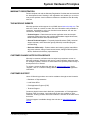
DOCUMENT LAYOUT
This Specification describes how to use the MOST ToGo System Hardware
Principles. The document is organized as follows:
• Chapter 1. “Overview”
• Chapter 2. “Basic System Structure”
• Chapter 3. “Power Management”
• Chapter 4. “Network Management”
• Chapter 4. “ECU Requirements”
• Chapter 5. “Harness Requirements”
• Appendix A. “Error Responses”
• Appendix B. “Glossary and General Terms”
CONVENTIONS USED IN THIS GUIDE
Within this manual, the following abbreviations and symbols are used to improve
readability.
Example
BIT
FIELD.BIT
x…y
BITS[m:n]
PIN
Description
Name of a single bit within a field
Name of a single bit (BIT) in FIELD
Range from x to y, inclusive
Groups of bits from m to n, inclusive
Pin Name
SIGNAL
Signal Name
msb, lsb
Most significant bit, least significant bit
MSB, LSB
Most significant byte, least significant byte
zzzzb
Binary number (value zzzz)
0xzzz
Hexadecimal number (value zzz)
zzh
Hexadecimal number (value zz)
rsvd
Reserved memory location. Must write 0, read value indeterminate
code
Instruction code, or API function or parameter
Multi Word Name
Used for multiple words that are considered a single unit, such as:
Resource Allocate message, or Connection Label, or Decrement Stack Pointer instruction.
Section Name
Emphasis, Reference, Section or Document name.
VAL
x
Over-bar indicates active low pin or register bit
Don’t care
<Parameter>
<> indicate a Parameter is optional or is only used under some conditions
{,Parameter}
Braces indicate Parameter(s) that repeat one or more times.
[Parameter]
Brackets indicate a nested Parameter. This Parameter is not real and actually decodes into
one or more real parameters.
DS20005241A-page 4
2013 Microchip Technology Inc.
System Hardware Principles
WARRANTY REGISTRATION
Please complete and mail the Warranty Registration Card that was enclosed with
the development board. Sending in the registration card entitles you to receive
new product updates. Interim software releases are available at the Microchip
web site.
THE MICROCHIP WEBSITE
Microchip provides online support via our WWW site at www.microchip.com. This
web site is used as a means to make files and information easily available to
customers. Accessible by using your favorite Internet browser, the web site
contains the following information:
• Product Support – Data sheets and errata, application notes and sample
programs, design resources, user’s guides and hardware support documents,
latest software releases and archived software
• General Technical Support – Frequently Asked Questions (FAQ), technical
support requests, online discussion groups, Microchip consultant program
member listing
• Business of Microchip – Product selector and ordering guides, latest Microchip press releases, listing of seminars and events, listings of Microchip sales
offices, distributors and factory representatives
CUSTOMER CHANGE NOTIFICATION SERVICE
Microchip’s customer notification service helps keep customers current on
Microchip products. Subscribers will receive e-mail notification whenever there
are changes, updates, revisions or errata related to a specified product family or
development tool of interest.
To register, access the Microchip web site at www.microchip.com. Under
“Support”, click on “Customer Change Notification” and follow the registration
instructions.
CUSTOMER SUPPORT
Users of Microchip products can receive assistance through several channels:
• Distributor or Representative
• Local Sales Office
• Field Application Engineer (FAE)
• Technical Support
Customers should contact their distributor, representative or Field Application
Engineer (FAE) for support. Local sales offices are also available to help
customers. A listing of sales offices and locations is included in the back of this
document.
Technical support is available through the web site at: http://microchip.com/
support
2013 Microchip Technology Inc.
DS20005241A-page 5
System Hardware Principles
RECOMMENDED READING
This user's guide describes how to use MOST ToGo System Hardware Principles and
references the following documents as recommended and supplemental resources.
Documents listed below and referenced within this publication are current as of
the release of this publication and may have been reissued with more current
information. To obtain the latest releases of Microchip documentation please visit
the Microchip website. Please note, some Microchip documentation may require
approval. Contact information can be found at www.microchip.com.
All non-Microchip documentation should be retrieved from the applicable website
locations listed below. Microchip is not responsible for the update, maintenance
or distribution of non-Microchip documentation.
Because the Internet is a constantly changing environment, all Internet links
mentioned below and throughout this document are subject to change without notice.
[1]
MOST Specification 3.0
Rev. 3.0 E2: Jul. 2010. MOST Cooperation. www.mostcooperation.com.
[2]
MOST FBlock EnhancedTestability Specification
Rev. 3.0.1, Jun. 2010. MOST Cooperation. www.mostcooperation.com.
[3]
Electrical Control Line Specification
Rev. 1.1.1, July 2011. MOST Cooperation. www.mostcooperation.com.
[4]
MOST INIC Hardware Concepts Specification
Microchip. www.microchip.com.
[5]
INIC API User Manual
OS81092 MOST50 INIC API User Manual. Rev 1.3.0-1, Dec. 2010. Microchip.
www.microchip.com.
[6]
Road vehicles - ISO 7637-2 Specification
Electrical disturbances from conduction and coupling
Part 2: Electrical transient conduction along supply lines only.
ISO 7637-2, May 2004, International Organization for Standardization. www.iso.org.
[7]
OS81092 INIC Hardware Data Sheet
DS81092AP3, Apr. 2011. Microchip. www.microchip.com.
[8]
MOST NetServices Layer 1 User Manual
V3.0.x-6, Jan. 2012. Microchip. www.microchip.com.
[9]
MOST NetServices Layer 2 User Manual
V3.0.x-6, Jan. 2012. Microchip. www.microchip.com.
[10] MOST Electrical Physical Layer Specification
Rev. 1.1, Jun. 2006. MOST Cooperation. www.mostcooperation.com.
[11] MediaLB Analyzer User Manual
V2.0.x-3, Mar. 2010. Microchip. www.microchip.com.
[12] MOST Dynamic Specification
Rev. 3.0.1, Dec. 2010. MOST Cooperation. www.mostcooperation.com.
[13] MOST FunctionBlock NetworkMaster Specification
Rev. 3.0.2, Mar. 2011. MOST Cooperation. www.mostcooperation.com.
DOCUMENT REVISION HISTORY
DS20005241A (11/2013)
MOST ToGo System Hardware Principles.
DS20005241A-page 6
2013 Microchip Technology Inc.
®
SYSTEM HARDWARE PRINCIPLES
Chapter 1. Overview
MOST ToGo can be understood as an exemplary implementation of a MOST50
(ePHY) or MOST150 (cPHY and oPHY) network, with a strong focus on teaching
“how things work”. While many of the concepts mentioned here are generic to either
MOST network, this document is currently targeted to the MOST50 network.
1.1
AUDIENCE
This document is written for engineers and developers who intend to provide entire
car platforms with MOST-based infotainment systems, or who aim to supply OEMs
with MOST devices. When starting with this subject, it is important to know how to
implement MOST technology into a MOST network device in a cost-effective and fast
way, while continuously considering product design and development-relevant
aspects of the project. Microchip has designed MOST ToGo, which is a package of
hardware, software, and documents, to assist in the implementation of the MOSTbased infotainment system. See the MOST Specification 3.0 [1] for additional
information on the MOST network.
This document is the System Hardware Principles Specification of MOST ToGo. The
goal of this document is to:
• Give an overview of an example system structure for an in-car entertainment system, based on MOST
• Describe parts of the Management layer including timing master, power master
and network master
• Explain the basics of the power management and depict various network wakeup
and network shutdown scenarios
• Give an overview of MOST network system states, explain the purpose of the network master and describe by means of scenarios the network’s functionality and
how it changes when MOST network slaves enter or leave the network
• Describe the Electronic Control Unit (ECU) and Electrical Control Line (ECL)
requirements
• Give an overview of responses to error conditions that can occur
2013 Microchip Technology Inc.
DS20005241A-page 7
®
SYSTEM HARDWARE PRINCIPLES
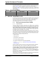
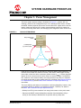
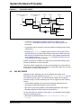
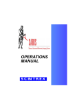
Chapter 2. Basic System Structure
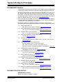
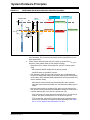
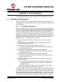
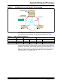
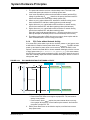
Figure 2-1 depicts an example system structure for an in-car infotainment system,
based on MOST. This example consists of the following devices:
• Head Unit (HU)
• Rear-Seat Entertainment system (RSE)
• Audio amplifier (AMP)
• Blu-ray Disk system (BD)
• GPS/SAT Tuner
The HU contains all the network management blocks.
FIGURE 2-1:
EXAMPLE SYSTEM STRUCTURE
8,
/D\HU
$SSOLFDWLRQ
/D\HU
+8
56(
8,
8,
)%ORFNV
)%ORFNV
$PS
%'
*366$77XQHU
8,&RPPXQLFDWLRQ
)%ORFNV
)%ORFNV
)%ORFNV
)%ORFN&RPPXQLFDWLRQ
6KDGRZV
0DQDJHPHQW
/D\HU
0DQDJHPHQW&RP
0600
3RZHU0DVWHU
3RZHU6ODYH
3RZHU6ODYH
3RZHU6ODYH
3RZHU6ODYH
6RXUFH
6RXUFH
1HWZRUN0DVWHU
&RQQHFWLRQ0DQDJHU
7LPLQJ0DVWHU
6:8SGDWH0DQDJHU
5HVRXUFH
/D\HU
6RXUFH
6LQN
6LQN
5HVRXUFH7UDQVPLVVLRQ
6LQN
)%ORFN
)%ORFN6KDGRZ
The functionality on each device is divided into four layers:
• The User Interface (UI) layer implements the user interfaces as well as their applications.
• The Application layer implements the MOST FBlocks (to communicate MOST
messages) as well as their applications.
• The Management layer controls and manages the system resources on the
MOST network.
• The Resource layer indicates the audio and video transmission capabilities.
DS20005241A-page 8
2013 Microchip Technology Inc.
System Hardware Principles
This document covers parts of the Management layer needed to get the MOST
network operational and includes physical hardware issues. The Management
layer described includes the MOST System Management Module (that
incorporates the power master, network master and connection manager) and
the timing master. The other blocks will be covered in a different document.
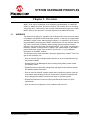
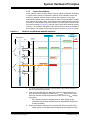
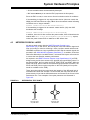
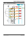
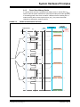
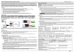
While the system management concepts generally apply to larger systems, for
the purposes of explanation this document focuses on the basic system
structure, as illustrated in Figure 2-2, which includes a Head Unit (HU), an
auxiliary input (AuxIn) device and an amplifier (Amp) device. The basic system
consists of two audio sources and one audio sink (Amp). Each audio source is
managed through the FBlock AuxIn, and the audio sink is managed through the
FBlock AudioAmplifier.
Since the connection manager resides in the HU and controls the FBlocks AuxIn
and AudioAmplifier, it also contains the FBlocks AuxIn Shadow and
AudioAmplifier Shadow so that it has local information about the status of the
auxiliary input and amplifier devices.
In addition to the FBlocks depicted in Figure 2-2, every device shall also contain
the following FBlocks:
• NetBlock
• (ET) MOST FBlock EnhancedTestability Specification [2]
• Diagnosis
FIGURE 2-2:
BASIC SYSTEM STRUCTURE
+8
8,
/D\HU
$SSOLFDWLRQ
/D\HU
$X[,Q
$PS
8,&RPPXQLFDWLRQ
8,
$X[,Q
)%ORFN&RPPXQLFDWLRQ
$X[,Q
$XGLR$PSOLILHU
$XGLR$PSOLILHU
&RQQHFWLRQ0DVWHU
1HWZRUN0DVWHU
$X[,Q6KDGRZ
$XGLR$PS6KDG
0DQDJHPHQW
/D\HU
0DQDJHPHQW&RP
0600
3RZHU0DVWHU
3RZHU6ODYH
3RZHU6ODYH
1HWZRUN0DVWHU
&RQQHFWLRQ0DQDJHU
7LPLQJ0DVWHU
5HVRXUFH
/D\HU
6RXUFH
6LQN
6RXUFH
5HVRXUFH7UDQVPLVVLRQ
6LQN
)%ORFN
2013 Microchip Technology Inc.
)%ORFN6KDGRZ
DS20005241A-page 9
System Hardware Principles
The network logical address for each ECU is defined using static addressing as
listed in Table 2-1; however, applications shall use the central registry to
determine the logical node address of a particular function block. Though shown
sequentially in Table 2-1, the relationship between logical address and ECL node
class is arbitrary.
TABLE 2-1:
2.1
ECU STATIC ASSIGNMENTS
ECU
Logical Address
ECL Node Class
Head Unit
0x0141
1
AuxIn
0x0162
2
Amplifier
0x0153
3
HEAD UNIT - MANAGEMENT LAYER
In the basic system the HU device contains all the MOST network management
blocks, which include the timing master, power master, network master and
connection manager (the latter two also contain FBlocks called FBlock
NetworkMaster and FBlock ConnectionMaster, respectively).
2.1.1
MOST System Management Module (MSMM)
2.1.1.1
POWER MASTER
The power master is a software component (not an FBlock) that is responsible
for waking the MOST network devices as well as managing the shut down of the
network. MOST network wakeup is done by asserting the common ECL wire.
Then, the network startup is accomplished by sending a command to the INIC
configured as the timing master device. The power master, timing master and
the network master are located in the same ECU.
The power master device (HU) also includes a CAN gateway and user interface,
both of which contain local events which indicate that the MOST network needs
to be woken and started. In this basic system, the events that shall cause the
MOST network to wakeup and stay active are:
• CAN: Door open
• CAN: Ignition on
• User Interface: Power-on button
• ECL WI slave wakeup assertion
• ECL System Test Start Pulse (TSI) test tool assertion
• Function ET.AutoWakeup() (see MOST FBlock EnhancedTestability
Specification [2])
Once the network devices are woken from sleep power state (ECL assertion),
then the power master’s job is to monitor for stable lock of the network.
The power master manages the MOST network shutdown through functions in
the FBlock NetBlock. The power master shall shutdown the network when the
engine is off and either the door is opened or a timeout occurs (tPM_SdTO2).
Through the NetBlock.Shutdown() function, the power master shall inform
all devices that it intends to power down the network. Any device is allowed to
delay power down if needed.
Only the device containing the timing master can contain the power master block.
All other devices in the network are defined as power slaves.
DS20005241A-page 10
2013 Microchip Technology Inc.
System Hardware Principles
2.1.1.2
NETWORK MASTER
Once the MOST network achieves stable lock, the network master software
component controls the system state of the network and manages the central
registry. The network master must reside on the timing master device which has
the physical address of 0x400. The FBlock NetworkMaster is part of the network
master software component, thus all devices can send their current state to the
NetworkMaster at physical address 0x400 (which never changes).
Devices can only communicate with the network master and not between each
other until the network master determines that the network/system is OK. Once
stable network lock is achieved, the network master component shall scan each
device in the network to determine what FBlocks are available and to make sure
no address conflicts exist. The network master broadcasts the system state
(either OK or NotOK) to all devices in the network.
2.1.1.3
CONNECTION MANAGER
The connection manager is a software component. The interface to the
connection manager is the FBlock ConnectionMaster, which is responsible for
building and removing streaming connections. The application will have some
form of an Audio-Video manager module which contains all of the logic that
determines which sources should be connected to the various sinks. This module
takes inputs from the HMI user interface and decides what should be connected,
then asks the ConnectionMaster to do the connections and disconnections. The
ConnectionMaster keeps a table of all of the currently connected devices.
The connection manager can reside on any device, but since it makes use of the
central registry it is convenient for it to also be located with the network master.
In the MOST ToGo system, the ConnectionMaster FBlock is in the HU module
along with the network master and power master.
2.1.2
Timing Master
The MOST network requires only one device be defined as the timing master. In
this system, the HU shall be the timing master device, and all other devices are
timing slaves. The INIC configured as the timing master sets the low-level
network timing (clock source, frame structure, etc.) for all other devices and also
gets the physical network address of 0x400.
• In all MOST systems, the network master shall reside on the timing master
device (required by MOST Specification 3.0 [1]).
• In MOST50 systems, the power master shall also reside on the timing master
device (not required but recommended).
2.1.2.1
NETWORK BANDWIDTH
The basic system structure (see Figure 2-2) consists of two sources (each source
is 16-bit stereo audio) and two sinks. Both sources are allowed to be on the
network at the same time, therefore the minimum network bandwidth required is
8 bytes (INIC.InstID.Bandwidth.AssignBWInit = 2). To support
expansion of sources, the streaming network bandwidth shall stay at the INIC
default value of 65 bytes (INIC.InstID.Bandwidth.AssignBWInit = 16).
Note that this setting on a MOST50 network allows up to 16 stereo sources on
the network simultaneously, while still reserving 46 bytes for the asynchronous
packet channel, equivalent to 17Mb/s of packet or IP type data.
2013 Microchip Technology Inc.
DS20005241A-page 11
®
SYSTEM HARDWARE PRINCIPLES
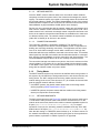
Chapter 3. Power Management
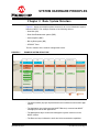
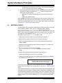
The basic system structure wiring is illustrated in Figure 3-1, with the HU only
showing a subset of the management layer to be described. Each device contains
the MOST network physical layer and a common-wired ECL signal which uses the
battery voltage and ground for a simple communications protocol for waking the
devices from sleep power state, and managing some diagnostics when errors occur.
FIGURE 3-1:
BASIC SYSTEM WIRING
%DWWHU\&RQWLQXRXV3RZHU
%DW&RQ3
+8
6OHHS3RZHU6WDWH
1HWZRUN0DVWHU
7LPLQJ0DVWHU
/RFDO:DNHXS(YHQWV
HJ&$1'RRU2SHQHG
3RZHU0DVWHU
02671HWZRUN
(&/
$PS
6OHHS3RZHU6WDWH
%DW&RQ3
$X[,Q
6OHHS3RZHU6WDWH
%DW&RQ3
Each device in the network is connected to continuous battery power (BatConP). To
minimize current when the vehicle is inactive, each device must support a sleep
power state, where the device consumes minimal current (ISTBY). Unless otherwise
stated, the ISTBY current must be under 150 µA at nominal voltage. For MOST50,
ECL assertion is the network wakeup event that causes every device to transition
from sleep power state to active power state. ECL is defined in the Electrical Control
Line Specification [3] and the MOST INIC Hardware Concepts Specification [4]
documents.
The terms wakeup and startup are sometimes used interchangeably; however, they
are distinct phases of getting to an operational network. Therefore, as stated in
the MOST INIC Hardware Concepts Specification [4]:
• Wakeup is an ECU power transition from sleep power state to active power state.
• Startup is the MOST network NetInterface transition from NetInterface Off (no
activity on the network) to NetInterface Init (network activity exists) state.
DS20005241A-page 12
2013 Microchip Technology Inc.
System Hardware Principles
3.1
NETWORK WAKEUP
Typically, the power master node manages network wakeup. When the power
master node receives a local wakeup event, it exits sleep power state and
qualifies the event to block errors/noise from causing unwarranted network
wakeup events. The following are power master local wakeup events:
• CAN: Door unlock
• CAN: Ignition on
• User Interface: Power-on button
• Function ET.AutoWakeup()(MOST FBlock EnhancedTestability
Specification [2])
The power master is typically connected to the gateway that receives engine
status, such as ignition on, which is a primary wakeup event. If the ignition is off,
then that wakeup event is no longer valid and the power master will cease trying
to start the network which prevents the power master from staying on and
draining the battery.
If the network is in sleep power state, and the power master receives a CAN door
unlock message, it will wakeup the network by asserting ECL with a series of
NEWU wakeup pulses (WI) (Electrical Control Line Specification [3]). ECL
assertion causes all network devices to wake from sleep power state. The power
master then starts up the network through a port message to INIC. Waking up
the network with the door unlock provides more time for ECU initialization
(although the UI will remain inactive until the engine is running or the power-on
button is pressed). The power master also starts a timer (tPM_SdTO1) that will
power the network back down if the engine doesn’t start.
If the HU power-on button is pressed, the UI becomes active and a separate
timer (tPM_SdTO3) keeps the network active until that timer expires or the car
engine is running.
The function ET.AutoWakeup() simulates a local wakeup event for compliance
testing (MOST FBlock EnhancedTestability Specification [2]).
To maintain stability when starting the network, the power master shall only
wakeup and startup the network when the battery voltage is in the UNormal range
(MOST INIC Hardware Concepts Specification [4]) (battery voltage exceeds
VTh_Active = VTh_Critical).
As stated in the Electrical Control Line Specification [3], when driving ECL, the
ECL initiator must simultaneously read back ECL to verify ECL is transitioning
properly and that ECL is not being driven by some other device.
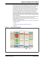
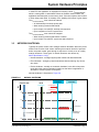
3.1.1
Normal Network Wakeup
For all ECUs (power master and power slaves), the following are normal network
wakeup events:
• ECL WI - wakeup pulse, used for normal network wakeup (see Figure 3-2).
• ECL TSI - ECL system test pulse, can wakeup all devices and indicates the
start of the ECL system test sequence (initiator is either the HU/power master
or an external test tool).
2013 Microchip Technology Inc.
DS20005241A-page 13
System Hardware Principles
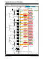
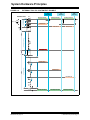
FIGURE 3-2:
POWER MASTER NETWORK WAKEUP SEQUENCE (NORMAL)
3RZHU0DVWHU
1HW,QWHUIDFH6WDWH
,1,&7;
7LPH
(&/
3RZHU0DVWHU
/RFDO:DNHXS
(YHQW
&$1'RRU2SHQHG
1HW2II
3RZHU6ODYHV
([LW6OHHS3RZHU6WDWH
W 30,QLW
W (:8
([LW6OHHS3RZHU6WDWH
7ULJJHU:,6HTXHQFH
6WDUWXS1HWZRUN
1 (:8 W 3DXVH
1HW,QLW
W (:8
$FWLYLW\
1HW2Q
/RFDO:DNHXS
(YHQW
&$1,JQLWLRQ2Q
1. The power master device receives a local wakeup event (e.g., CAN: door
open message). The local event causes the power master device to exit
sleep power state.
2. Power master determines that the ECU voltage is greater than VTh_Active;
therefore, power master starts up the network normally.
• Becomes an ECL initiator and asserts ECL (start of a wakeup pulse
(WI)).
- EHC initializes MOST NetServices as fast as possible.
- And EHC starts up the MOST network.
• ECL assertion wakes all power slave devices (any IC that had power
removed in sleep power state must be reset properly when exiting sleep
power state). EHCs initialize MOST NetServices as fast as possible and
wait for network activity.
- INICs detect network activity and set NetInterface State to NetInit.
- Once the network achieves stable lock, the NetInterface State goes to
NetOn.
• All power slaves must be monitoring ECL after tPSInit has expired.The
ECL pulses must be measured and validated to determine if the pulse is
a normal wakeup (WI) or the start of a system test (TSI).
- If WI is detected, the event should be recorded, but no specific action
is taken. Any other pulses that are not TSI should be ignored.
- If TSI is detected, then an ECL system test is being initiated and the
power slave must enter the system test participant stage (see Appendix A.1.2 “ECL System Test and Stable Lock Test”).
DS20005241A-page 14
2013 Microchip Technology Inc.
System Hardware Principles
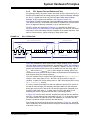
3.1.2
Power Slave Wakeup
Some systems need to support multiple devices waking the network. Examples
of power slaves needing to wakeup the network are a telematics device that
receives a wireless call and needs to wakeup the network or a rear-seat
entertainment system with a remote power-on button. Since the MOST network
only supports one power master, some power slave mechanisms are required for
the slave to communicate to the power master. The basic system defined in this
document as shown in Figure 3-1 does not require power slave wakeup support;
however, it is included in the MOST ToGo slave devices to show an example of
slave wakeup. The power slave wakeup sequence is shown in Figure 3-3 below.
FIGURE 3-3:
POWER SLAVE NETWORK WAKEUP SEQUENCE
3RZHU0DVWHU
1HW,QWHUIDFH6WDWH
3RZHU6ODYH
ZLWK:DNHXS
,1,&7;
7LPH
3RZHU0DVWHU
(&/
2WKHU3RZHU6ODYHV
([LW6OHHS3RZHU6WDWH
/RFDO
:DNHXS
(YHQW
W 36,QLW
W (:8
([LW6OHHS3RZHU6WDWH
1HW2II
1 (:8 ([LW6OHHS3RZHU6WDWH
7ULJJHU:,6HTXHQFH
W 3DXVH
W (:8
9DOLGDWH(&/
W (:8
7ULJJHU:,6HTXHQFH
6WDUWXS1HWZRUN
1 (:8 1HW,QLW
W (:8
$FWLYLW\
1HW2Q
1. The power slave device receives a local wakeup event, which causes the
device to exit sleep power state.
2. Local event is qualified by the application (valid event that needs the network) and the ECU voltage is greater than VTh_Active; therefore, the power
slave becomes ECL initiator and asserts ECL with a series of NEWU wakeup
pulses (WI).
- ECL assertion wakes all remaining devices, which power up and
resets INIC (and possibly the EHC). EHCs initialize MOST NetServices
as fast as possible.
3. Power slave with the wakeup event reasserts ECL WI (up to NEWU times).
- Power master is now awakened and initialized and measures this sec-
2013 Microchip Technology Inc.
DS20005241A-page 15
System Hardware Principles
ond ECL pulse. Note that the value of NEWU may need to be increased
to 3 or 4, so that the last WI pulse is after tPMInit.
4. Power master determines that the second (or subsequent) ECL pulse is valid
and the ECU voltage is greater than VTh_Active; therefore, power master
starts up the network normally.
- Becomes ECL initiator and starts its own series of NEWU ECL pulses
(WI)
- Starts up the MOST network
After sending its last WI pulse, the power slave must monitor the ECL line for
incoming ECL WI pulses from the power master. If the power slave does not
detect any WI pulses within tPSW_Retry, then it will initiate retries as described in
Appendix A.1.3 “Power Slave Wakeup Retries”.
3.2
NETWORK STARTUP
As stated above, when the power master asserts the ECL WI pulses it must also
start the MOST network. This is done by sending the INIC message:
INIC.InstID.NWStartup.StartResult which is triggered by the
NetServices API function MostStartup(MNS_MASTER, MNS_DEFAULT). Since the
MOST ToGo system uses MSMM for the power master function, this action can
be triggered by the MSMM API call msm_PM_NetworkStartup(MNS_MASTER).
Once INIC receives the NWStartup message, it will:
• Start sending modulated signal (network frames) on the network
• Begin looking for network frames on its RX (input) network port
• When frames are detected on the RX input, the network state moves from
NetOff to NetInit.
• When the incoming frames have been valid and locked for tLock (100ms), the
state will move to NetOn.
• INIC will respond to the EHC with the message:
INIC.InstID.NWStartup.Result indicating a successful network
startup.
If frames are not detected at the RX network input, INIC will:
• Continue to send frames for up to tConfig (2 seconds).
• If nothing is detected by the time tConfig expires, INIC will wait tRestart (300 ms)
then respond to the EHC with INIC.InstID.NWStartup.Error.
Note:
NetInterface Normal, NetInterface Off and NetInterface Init states are also commonly referred to
as NetOn, NetOff and NetInit, respectively.
If the EHC receives the INIC.InstID.NWStartup.Error message, the
power master can initiate retries as described in Appendix A.1 “Network Startup
Errors”.
If the network startup was successful and the network state reached NetOn, then
the power master will trigger the network master functionality of MSMM to start
the system scan and build the central registry. At this time, the power master has
done its job of waking and starting the network. It will be called into action again
when it is time to do a network shutdown, or if an unexpected network break
occurs.
DS20005241A-page 16
2013 Microchip Technology Inc.
System Hardware Principles
In each ECU the application is responsible for keeping a timer, tPwrSwitchOffDelay,
which is running when in state NetOff. When the network reaches NetOn, the
application should stop the tPwrSwitchOffDelay timer. If the timer expires, then it is time
to enter sleep power state. A summary of the handling of this timer is given below:
The tPwrSwitchOffDelay timer should be started:
• At initial wakeup from sleep power state.
• When entering network state NetOff.
• Upon receipt of a valid ECL wakeup start sequence.
• Upon completion of an ECL system test.
The tPwrSwitchOffDelay timer should be stopped:
• When entering network state NetInit or NetOn.
• Upon receipt of a valid ECL system test start sequence.
3.3
NETWORK SHUTDOWN
Typically the power master node manages network shutdown. When the power
master node receives local events indicating that network should be powered
down, the power master goes through a sequence of events to do an orderly
network shutdown. Three types of network shutdown are defined by
MOST Specification 3.0 [1]:
• Normal shutdown - managed by the power master and described below
• Error shutdown - emergency network shutdown without warning. Any device
can cause.
• Device shutdown - actually not a network shutdown, but a device low-power
mode where the network operates normally, but the device’s application is
shutdown to minimize power consumption.
Normal shutdown is illustrated in Figure 3-4
FIGURE 3-4:
NORMAL SHUTDOWN.
1HW,QWHUIDFH6WDWH
3RZHU0DVWHU
3RZHU6ODYHV
,1,&7;
7LPH
3RZHU0DVWHU
/RFDO:DNHXS(YHQW
&$1,JQLWLRQ2II
/RFDO:DNHXS(YHQW
1HW%ORFN6KXWGRZQ4XHU\
&$1'RRU2SHQ
$FWLYLW\
1HW2Q
W :DLW6XVSHQG
1HW%ORFN6KXWGRZQ([HFXWH
W 6KXW'RZQ:DLW
W 6ODYH6KXWGRZQ
6KXWGRZQ1HWZRUN
1HW2II
)RUFHV1HWZRUN2II
LIQRWDOUHDG\RII
W 3ZU6ZLWFK2II'HOD\
2013 Microchip Technology Inc.
(QWHU6OHHS3RZHU6WDWH
(QWHU6OHHS3RZHU6WDWH
DS20005241A-page 17
System Hardware Principles
1. Power master has received local events indicating the network needs to be
shutdown (ignition off and door open). Power master initiates request stage
of network shutdown.
• Power master broadcasts NetBlock.InstID.Shutdown(Query) to
all power slaves and starts its tWaitSuspend timer.
- Power slaves that need more time to power down can return NetBlock.InstID.Shutdown(Suspend).
2. If power master does not receive a suspend request before tWaitSuspend times
out, the power master broadcasts the NetBlock.InstID.Shutdown(Execute) message.
• When power slaves receive this message, they start their tSlaveShutdown
timer. If this timer expires and the NetInterface is not in the NetOff state,
the power slaves force the network off through the INIC.NWShutdown() function.
3. Power master waits tShutDownWait after broadcasting NetBlock.InstID.Shutdown(Execute) before issuing an INIC.NWShutdown() command, which shuts down the network.
• When the NetInterface transitions to NetOff, every device starts a power
down timer, tPwrSwitchOffDelay.
4. If the NetInterface stays in the NetOff state and tPwrSwitchOffDelay expires,
then each device reverts to sleep power state.
• To enter sleep power state, the EHC sends the INIC API message
INIC.PMIState.Set(PWROFF_HI) which releases the PWROFF pin to
the power management circuitry causing the device to power down.
The second type of shutdown, error shutdown, can occur if the voltage transitions
into the ULow region or a device has a severe over-temperature condition. In
these cases, no power master request stage occurs. The device in the
emergency situation can force the network off.
The third type of shutdown, device shutdown, is a device low-power state where
the network is still fully operational (NetInterface Normal Operation), but the rest
of the device is consuming minimal power. The power master can target specific
devices to enter device shutdown, while other devices are still fully operational.
In the basic MOST ToGo system, device shutdown is not supported.
A wakeup event has priority over network shutdown. If the power master receives
a wakeup event after broadcasting NetBlock.InstID.Shutdown(Execute),
the power master shall finish the shutdown sequence, then restart the network
after tRestart (MOST Specification 3.0 [1]) has expired.
DS20005241A-page 18
2013 Microchip Technology Inc.
System Hardware Principles
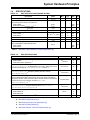
3.4
SPECIFICATIONS
TABLE 3-1:
EHC SPECIFICATIONS (RANGE VALUES)
Description
ECL short-to-ground detection. 1
Name
Min.
tECL_Low
1
Typ.
Max.
Unit
s
Time from initial edge of a wakeup event from sleep power
state to being able to measure or assert ECL.
Power master:
Power slaves (also tECLDetect_Max). 1
tPMInit
tPSInit
180
500
ms
Sleep power state current (VBAT_ECU = 12 V)
ISTBY
150
µA
Network shutdown voltage.
1
Network startup voltage.
Power master:
Power slaves: 1
Network over voltage (not currently used). 1
VTh_Low
6.0
6.5
7.0
V
VTh_Active, VTh_Critical
8.5
7.5
9
8
9.5
8.5
V
16
16.5
V
VTh_Super
15.5
ECL hardware glitch protection. 1
tGlitch
50
Delay from rising edge of ECL (when exiting sleep power
state) to initialization of MOST NetServices.
Power master:
Power slaves:
tNS_Init
Note 1:
TABLE 3-2:
µs
200
500
ms
See MOST INIC Hardware Concepts Specification [4]
EHC SPECIFICATIONS
Description
Network startup attempts (per startup sequence).
Power master:
Power slaves (ECL assertions): 1
Name
Value Unit
NNtwStartup
4
4
--
Time a power slave will wait after receiving NetBlock.InstID.ShutDown.Start(Execute) for NetInterface to go to Off or power slave forces
the network off through the INIC.NWShutdown() function. 2
tSlaveShutdown
16
s
Time the power master will wait after sending NetBlock.InstID.ShutDown.Start(Execute) followed by shutting down the network
(INIC.NWShutdown()). 2
tShutDownWait
2
s
tPwrSwitchOffDelay
20
s
tWaitSuspend
2
s
NEWU
2
2
--
mc
15
--
Time from NetOff to reverting to sleep power state. When exiting sleep power
state, the NetInterface state is assumed off, so this timer starts. This timer is
managed by the EHC. When the timer expires, the EHC should command INIC
to release its PWROFF pin with the command INIC.PMI-
State.Set(PWROFF_HI) 2
Time the power master waits after broadcasting NetBlock.InstID.Shutdown.Start(Query) for power slaves to return NetBlock.InstID.Shutdown.Result(Suspend). 2
ECL wakeup pulses (WI) per wakeup attempt.
Power master WI:
Power slaves WI:
ECL maximum number of node classes. 3
Note 1:
See MOST INIC Hardware Concepts Specification [4]
2:
See MOST Specification 3.0 [1]
3:
See Electrical Control Line Specification [3]
4:
See INIC API User Manual [5]
5:
See Road vehicles - ISO 7637-2 Specification [6]
2013 Microchip Technology Inc.
DS20005241A-page 19
System Hardware Principles
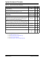
TABLE 3-2:
EHC SPECIFICATIONS (CONTINUED)
Description
ECL TSI pulses per system test start sequence.
Power master TSI:
External test tool TSI:
Power slave wakeup retry. Time between network wakeup attempts if network
activity or ECL assertion by another device does not occur.
ECL system test startup delay after TSI. 3
Function INIC.WatchdogMode():
Power master:
Power slaves: 4
Function INIC.RemoteAccess().
Name
Value Unit
NTSI
3
3
--
tPSW_Retry
300
ms
tStartup
200
ms
Timeout
500
AutoShutDownDelay 20,000
AutoShutDownDelay 65,535
ms
AccessMode
1
Property INIC.PMIConfig.Config. Controls how INIC handles the
PWROFF pin and network Tx signal in various power conditions and network
states.This is set in the Configuration String and this value reflects what is
described as the “New Behavior” in the INIC API manual.
PMIConfig
0x1C
Property INIC.PIMConfig.TimePwrOff: This is backup timer maintained
by INIC, running only when in NetOff and the EHC is not attached. When timer
expires, sets the PWROFF pin to high. Value is set in the Configuration String.
tTimePwrOff
60
s
Power master shutdown time out 1. Maximum time between door open and ignition on events. If this timer expires, power master performs network shutdown.
tPM_SdTO1
60
s
Power master shutdown time out 2. Maximum time between ignition off and door
open events. If this timer expires, power master performs network shutdown.
tPM_SdTO2
120
s
Power master shutdown time out 3. Maximum time between UI triggered startup
and ignition on events. If this timer expires, power master performs network shutdown.
tPM_SdTO3
600
s
Us
Ua
t7
t9
-7
-4.9
20
10
V
V
ms
s
ISO 7637-2 crank pulse 4 (see Section 6.6) values. For all other values.5
Note 1:
--
See MOST INIC Hardware Concepts Specification [4]
2:
See MOST Specification 3.0 [1]
3:
See Electrical Control Line Specification [3]
4:
See INIC API User Manual [5]
5:
See Road vehicles - ISO 7637-2 Specification [6]
DS20005241A-page 20
2013 Microchip Technology Inc.
®
SYSTEM HARDWARE PRINCIPLES
Chapter 4. ECU Requirements
For robustness, INIC must be able to power up properly, lock to the network, and
revert to sleep power state if the EHC never attaches. Therefore, the INIC PWROFF
pin must go to the power management circuitry to manage the transition between the
sleep power state and active power state. As long as the EHC maintains its
connection to INIC through regular communication, keeping INIC in the attached
state or the network is in state NetOn, INIC will keep the PWROFF pin low keeping
the device powered up. When it is time to go to sleep power state, the EHC can
control the PWROFF pin via the INIC.PMIState.Set(PWROFF_HI) command.
The EHC can further limit reverting to sleep power state by using its own GPIO pin
to the power management circuitry. If the EHC uses a GPIO in lieu of, or in addition
to the INIC PWROFF pin, the EHC’s GPIO reset default must not impede reverting
to sleep power state (must be high impedance).
INIC.RemoteAccess() must be enabled to allow remote ECU testing. An example
test is for a remote network tool to send the device an INIC.Reset() command
either resetting the INIC, the EHC or both. The expected result is the EHC recovers
properly from any local reset event.
For a detailed explanation of the hardware concepts for a MOST network device as
well as hardware implementation examples, see the MOST INIC Hardware Concepts
Specification [4].
4.1
RESETS
At initial power up or when exiting from sleep power state, INIC must be powered
and properly reset independently of EHC. This scenario allows the network to
become operational regardless of the state of the EHC.
The reset generator must be designed to assert reset over the proper voltage range
and over the entire temperature range to insure that in a brown-out condition INIC
gets a proper reset. The lower limit of reset is specified in the OS81092 INIC
Hardware Data Sheet [7], section ‘Guaranteed Operating Conditions’. The upper limit
of reset assertion shall be just below the absolute minimum of the network switched
power supply voltage (NwSwP) as described in the MOST INIC Hardware Concepts
Specification [4]. Therefore, a trade-off exists between the accuracy of the switched
network power supply connected to INIC and the accuracy required in the reset
generator. For example, if the NwSwP power supply is ±2%, then the reset generator
must assert between 0.98xNwSwP and 0.9xNwSwP. However, if the NwSwP power
supply is ±5%, then the reset generator must assert between the tighter range of
0.95xNwSwP and 0.9xNwSwP.
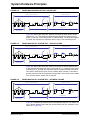
As illustrated in Figure 4-1, the INIC RSOUT pin shall be attached to the EHC reset
line. The EHC shall have a GPIO line connected to the INIC RST (reset) pin.
2013 Microchip Technology Inc.
DS20005241A-page 21
System Hardware Principles
FIGURE 4-1:
ECU RESET CIRCUIT
Protected Continuous Power
(ProConP)
Network Switched Power
(NwSwP)
Switched
Switched
Network
Network
Regulators
Regulators
NwSwP
NwSwP
RST
NwSwP
RST
Companion
(optional)
INIC
MediaLB
NwSwP
RSOUT
Enable
Reset
Generator
D3
D4
(if no internal
EHC POR)
NwSwP
EHC
RESET
GPIO (open-drain)
The EHC shall only assert the INIC RST pin under the following conditions:
• If explicitly commanded by the MOST NetServices callback function
reset_fptr. See MOST NetServices Layer 1 User Manual [8] for more
information.
• In conjunction with an update to a device’s software including the INIC Configuration String.
• Reception of ET.Reset() message (See the MOST FBlock EnhancedTestability Specification [2]). When this message is received, the EHC must reset
INIC and then reset itself (entire device reset). This message manifests itself
as the callback function ET_Reset_Request See MOST NetServices Layer
2 User Manual [9] for more information.
Outside of the above conditions, the EHC must not reset INIC during normal
firmware initialization or normal operation.
The device power management circuitry must be designed to ensure that the
device does not inadvertently power down into sleep power state due to a reset
of the EHC or a reset of INIC (or both).
4.2
INIC WATCHDOG
Although the INIC watchdog timer can be disabled during initial code
development, the INIC watchdog timer (see INIC.WatchdogMode() INIC API
User Manual [5] and Table 3-1 for values) shall be enabled for all network
multinode testing. The INIC watchdog timer can be triggered by the following
events:
• An INIC status message is not returned from the EHC within the timeout
period after an INIC data message is sent to the EHC.
• INIC does not receive any MOST Control Message (MCM) or INIC Control
Message (ICM) from the EHC within the timeout period.
Per the OS81092 INIC Hardware Data Sheet [7], a watchdog timeout (trigger)
causes the following actions:
• INIC enters the protected state (INIC.InstID.EHCIState.EHCI_Protected).
DS20005241A-page 22
2013 Microchip Technology Inc.
System Hardware Principles
• All user-created sockets are automatically destroyed.
• INIC asserts RSOUT pin to reset the EHC (requirement in this system).
Since the EHC is reset, it must recover from this situation under all conditions.
If the watchdog is triggered in any network slave device (does not contain the
NWM), the INIC also sends an empty FBlock list to the network master indicating
its FBlocks are no longer available:
0x0400: NetBlock.InstID.FBlockIDs.Status()
If the watchdog is triggered in the network master device (HU), then INIC
broadcasts the message:
0x03C8: NWM.InstID.Configuration.Status(NotOK)
In addition, since the HU also contains the power master, INIC will shutdown the
network after INIC.InstID.WatchdogMode.AutoShutDownDelay expires,
unless the power master EHC re-attaches to INIC before then.
4.3
NETWORK PHYSICAL LAYER
All devices shall comply with the MOST Electrical Physical Layer
Specification [10]. In the device, the PCB layout of the INIC network signal and
front end routing is critical to achieving a clean, low-jitter network which meets
OEM EMC requirements. Layout guidelines for INIC and the network signals are
provided in the OS81092 INIC Hardware Data Sheet [7]. In addition, all devices
shall utilize Microchip’s free MOSTCheck™ schematic and layout review service
to ensure the best possible network performance.
As required in the MOST Electrical Physical Layer Specification [10], all PCB
designs must provide clean access to the physical layer specification points. For
the electrical PHY, the four points are SP1E, SP2E, SP3E, and SP4E. While the
SP2E and SP3E points could be accessed through the harness connector, the
SP1E and SP4E points require test points on the PCB (ideally all four points
would be available on the PCB).
These test points should be routed such that integrity of the differential pair is
maintained and stubs are avoided. For best results, the test points should be
placed directly in-line with the differential traces and located at the far end of the
transmission line. Two examples of test point placement are illustrated in
Figure 4-2.
FIGURE 4-2:
DIFFERENTIAL TEST POINTS
Differential
Test Points Using
Only SMD Pads
2013 Microchip Technology Inc.
Differential
Test Points Using
100 Mil Header
DS20005241A-page 23
System Hardware Principles
4.4
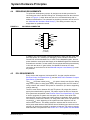
DEBUGGING REQUIREMENTS
To speed the development process, all designs must include provisions for
connecting test tools to the INIC Debug Port. All designs shall use the connector
shown in Figure 4-3, which allow test tools to be connected directly with no
additional modifications. The schematic for the debug connector can be found in
the OS81092 INIC Hardware Data Sheet [7]. The debug connector may be
depopulated on production boards.
FIGURE 4-3:
INIC DEBUG CONNECTOR
3.3 V
9
DSDA/TDI
DSCL/TCK
8
3.3 V
GND
6
DINT/TDO
RST
NC
4
TMS
1
GND
7
5
3
2
15
NC
NC
1
2
3
4
GND
DSDA/TDI
3.3 V
5
6
7
8
9
10
DINT/TDO
NC
11
12
13
14
Würth Elektronik
Molex
68711414522
87832‐1420
(or similar)
(or similar)
GND
ERR/BOOT
3.3 V
DSCL/TCK
GND
RST
TMS
In addition, the communication interface between the EHC and INIC must also
have test points, at a minimum for debugging. These interfaces include the
Control Port and the MediaLB Port, if used. For the MediaLB signals, the test
points should be routed such that integrity of the MediaLB signals are maintained
and stubs are avoided. For best results, the test points should be placed directly
in-line with the traces. If space allows, the MediaLB connector for direct
connection to the Active-Pod of the MediaLB Analyzer User Manual [11] would
be preferred.
4.5
ECL REQUIREMENTS
Every device shall support a bi-directional ECL line that complies with the
Electrical Control Line Specification [3] and the MOST INIC Hardware Concepts
Specification [4] document.
The tPMInit (for power master) and tPSInit (for power slaves) start from the falling
edge of ECL (when in sleep power state). After these times, the ECU must be
ready to detect and measure ECL pulses or assert ECL (for devices supporting
network wakeup).
The ECU must discern between WI and TSI pulses. WI pulses after network
activity has started shall be ignored. TSI pulses require the ECU to follow the
ECL system test as specified in the Electrical Control Line Specification [3]. Once
a device recognizes a system test start pulse, the device must refrain from
asserting ECL until the system test results sequence completes. Since a system
test could occur when the network is in sleep power state, three TSI pulses are
required (NTSI) at the beginning of the system test start sequence from an
external ECL test tool. This startup sequence assures that all devices are in
active power state and have had sufficient time to initialize (tPMInit and tPSInit have
expired). All devices are required to measure at least one TSI pulse to properly
detect the start of a system test. See Section A.1.2 “ECL System Test and Stable
DS20005241A-page 24
2013 Microchip Technology Inc.
System Hardware Principles
Lock Test” for more details.
When asserting ECL, the hardware shall not be damaged if the ECL line is
shorted to the battery positive voltage. In addition to current limiting as required
in Electrical Control Line Specification [3], the EHC shall detect the short-topower condition and report the condition to the power master’s FBlock Diagnosis.
When ECL is detected low for tECL_Low, the error condition shall be reported to
the power master’s FBlock Diagnosis. If ECL is shorted low, the device shall
revert to sleep power state when the network is shutdown and tPwrSwitchOffDelay
has expired (i.e., ECL shorted low must not prevent the device from powering
down). The device must also recover if the ECL line short-to-ground is removed,
and wake from sleep power state on the next ECL assertion.
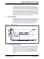
4.6
VOLTAGE DROPOUT
As mentioned in Section 4.1 “Resets”, the device’s internal reset detector must
be capable of surviving brown-out conditions. Another requirement is the device
must pass ISO 7637-2 (Road vehicles - ISO 7637-2 Specification [6]) test pulse
4, crank pulse test, to Class A status with respect to the MOST network
communications (no disruption in communications). This requires the device
contain charge reserves to survive the t7 time illustrated in Figure 4-4
FIGURE 4-4:
CRANK PULSE TEST.
VBAT_ECU
UB = 12 V
Ua
20 ms
Us
10 s
7.1 V
VTh_Low = 6.5 V
5V
0
4.7
t10
t7
t8
t9
t11
Time
INIC CONFIGURATION STRING
The INIC chip contains an INIC Configuration String that manages the default
INIC configuration for a given system architecture. Some of the parameters affect
the power up default and can be changed later by the EHC with FBlock INIC
commands, while other parameters are only configurable through the INIC
Configuration String. Table 3-2 contains INIC Configuration String parameters
(e.g., INIC.InstID.PMIConfig.TimePwrOff) for this basic system
architecture. The INIC Configuration String is defined in the INIC API User
Manual [5].
2013 Microchip Technology Inc.
DS20005241A-page 25
System Hardware Principles
The ECU must be designed with a plan for production programming of the INIC
Configuration String. As stated in INIC API User Manual [5], the INIC
Configuration String can be programmed through the Debug Port (the connector
is mentioned in Section 4.4 “Debugging Requirements”), also referred to as
customer configuration interface. The more common method of production
programming is through the Control Port by EHC code only used during
production. If the Control Port is already used for EHC-INIC communications,
then the same interface supports INIC Configuration String programming.
However, if MediaLB is the primary interface, then some other accommodation
must be made for INIC Configuration String programming on the production line.
DS20005241A-page 26
2013 Microchip Technology Inc.
®
SYSTEM HARDWARE PRINCIPLES
Chapter 5. Harness Requirements
To achieve better performance of the physical layer and provide margin, the following
specifications supersede the MOST Electrical Physical Layer Specification [10] which
states the minimum requirements over all conditions.
TABLE 5-1:
HARNESS SPECIFICATIONS
Description
Condition
Wire harness cable
Unshielded twisted pair
Cable guage
0.22 mm2
Twist length
Less than 12 mm
Untwisted wire length max. (at connectors)
Less than 5 cm
Cable characteristic impedance
130 +10/-30
Number of network ECUs
20 maximum
Number of connectors between ECUs
6 inline connectors maximum
Wire length between ECUs
10 m maximum
2013 Microchip Technology Inc.
DS20005241A-page 27
®
SYSTEM HARDWARE PRINCIPLES
Appendix A. Error Responses
This appendix describes the proper responses to error conditions that can occur.
A.1
NETWORK STARTUP ERRORS
Section 3.2 “Network Startup” describes standard network startup procedures. This
section expands on the requirements if the network fails to achieve state NetInterface
Normal Operation.
A.1.1
Power Master Startup Retries
When a local wakeup event occurs on the power master, it attempts to startup the
network. If the network fails to achieve state NetInterface Normal Operation, then the
power master shall make further attempts to startup the network. These attempts are
defined as a startup sequence, where the total number of attempts is defined as
NNtwStartup. If at the end of the startup sequence the network still has not achieved
state NetInterface Normal Operation (NetOn), the power master rechecks the local
wakeup event. If the local wakeup event is not active, then the power master shall
start an ECL system test (See the Electrical Control Line Specification [3]), as
illustrated in Figure A-1. The sequence of events are:
1. The power master detects a local wakeup event (e.g., HU power-on button
pressed).
2. Power master asserts ECL with a series of NEWU WI pulses (wakes up all
devices) and starts up the network.
3. Power master receives message that network startup failed.
• Power master reasserts ECL with another series of NEWU WI pulses and tries
to startup the network again.
4. Power master receives message that network startup failed again.
• Power master reasserts ECL with another series of NEWU WI pulses and tries
to startup the network again.
5. Power master receives message that network startup failed again.
• Power master reasserts ECL with another series of NEWU WI pulses and tries
to startup the network again.
6. Power master completes a full startup sequence (NNtwStartup = 4) and the network startup still fails.
• Power master then checks local wakeup event - which is no longer asserted.
- Then power master starts the ECL system test P[1:5] = 00100b which is
the Stable Lock test.
• When the ECL system test is finished, the power master stores the results
and reverts to sleep power state after tPwrSwitchOffDelay.
The above description assumes the local wakeup event is not asserted at the end of
the startup sequence. Figure A-2 illustrates the condition where a local wakeup event
is still active when the startup sequence is finished. The power master will initiate a
second startup sequence and then a third startup sequence. At the end of the third
startup sequence, in this example, the local wakeup event is no longer active (ignition
off); therefore the power master shall start the ECL system test P[1:5] = 00100b.
DS20005241A-page 28
2013 Microchip Technology Inc.
System Hardware Principles
FIGURE A-1:
POWER MASTER STARTUP SEQUENCE
3RZHU0DVWHU
3RZHU6ODYHV
1HW,QWHUIDFH6WDWH
7LPH
(&/
0267
1HWZRUN
/RFDO:DNHXS(YHQW
1HW2II
3RZHU2Q%XWWRQ
W (:8
7ULJJHU:,6HTXHQFH
1 (:8 ([LW6OHHS3RZHU6WDWH
6WDUWXS1HWZRUN
W 3DXVH
$FWLYLW\
1HW,QLW
W (:8
1HWZRUN6WDUWXS(UURU
7ULJJHU:,6HTXHQFH
2
([LW6OHHS3RZHU6WDWH
6WDUWXS1HWZRUN
1 (:8 5HWU\5
1
1WZ6WDUWXS
$FWLYLW\
1HW,QLW
1HWZRUN6WDUWXS(UURU
7ULJJHU:,6HTXHQFH
6WDUWXS1HWZRUN
1HWZRUN6WDUWXS(UURU
7ULJJHU:,6HTXHQFH
2
5HWU\5
1 (:8 $FWLYLW\
2
6WDUWXS6HTXHQFH
1HW,QLW
11ZN6WDUWXS 6WDUWXS1HWZRUN
1 (:8 1HWZRUN6WDUWXS(UURU
7ULJJHU76,6HTXHQFH
76,
W 3DXVH
6\VWHP7HVW6WDUW6HTXHQFH
76,
5HWU\5
W
W
2013 Microchip Technology Inc.
76,
W 3DXVH
1HW2II
1 76, $FWLYLW\
1HW,QLW
W
DS20005241A-page 29
System Hardware Principles
FIGURE A-2:
POWER MASTER MULTIPLE STARTUP SEQUENCES
0267
1HWZRUN
(&/
3RZHU0DVWHU
/RFDO:DNHXS
(YHQW
7LPH
&$1'RRU2SHQ
7ULJJHU:,6HTXHQFH
1 (:8 3RZHU6ODYHV
([LW6OHHS3RZHU6WDWH
6WDUWXS1HWZRUN
([LW6OHHS3RZHU6WDWH
1HWZRUN6WDUWXS(UURU
7ULJJHU:,6HTXHQFH
1 (:8 6WDUWXS6HTXHQFH
5
11ZN6WDUWXS 1 (:8 /RFDO:DNHXS
(YHQW
&$1,JQLWLRQ2Q
7ULJJHU:,6HTXHQFH
5
6WDUWXS1HWZRUN
1HWZRUN6WDUWXS(UURU
6WDUWXS1HWZRUN
/RFDO:DNHXS
(YHQW
&$1,JQLWLRQ2Q
7ULJJHU:,6HTXHQFH
1 (:8 1HWZRUN6WDUWXS(UURU
6WDUWXS1HWZRUN
5
1HWZRUN6WDUWXS(UURU
7ULJJHU:,6HTXHQFH
1 (:8 /RFDO:DNHXS
(YHQW
&$1,JQLWLRQ2Q
7ULJJHU:,6HTXHQFH
6WDUWXS6HTXHQFH
1 (:8 11ZN6WDUWXS 1 (:8 6WDUWXS1HWZRUN
1HWZRUN6WDUWXS(UURU
6WDUWXS1HWZRUN
5
1HWZRUN6WDUWXS(UURU
7ULJJHU:,6HTXHQFH
5
&$1,JQLWLRQ2Q
7ULJJHU:,6HTXHQFH
1 (:8 5
/RFDO:DNHXS
(YHQW
&$1,JQLWLRQ2Q
6WDUWXS1HWZRUN
/RFDO:DNHXS
(YHQW
7ULJJHU:,6HTXHQFH
1 (:8 1HWZRUN6WDUWXS(UURU
6WDUWXS1HWZRUN
1HWZRUN6WDUWXS(UURU
6WDUWXS1HWZRUN
/RFDO:DNHXS
(YHQW
&$1,JQLWLRQ2Q
7ULJJHU:,6HTXHQFH
1 (:8 1 (:8 6WDUWXS1HWZRUN
5
6WDUWXS6HTXHQFH
11ZN6WDUWXS 1HWZRUN6WDUWXS(UURU
1HWZRUN6WDUWXS(UURU
7ULJJHU:,6HTXHQFH
5
6WDUWXS1HWZRUN
/RFDO:DNHXS
(YHQW
&$1,JQLWLRQ2Q
7ULJJHU:,6HTXHQFH
1 (:8 1HWZRUN6WDUWXS(UURU
6WDUWXS1HWZRUN
5
W 76,
DS20005241A-page 30
6\VWHP7HVW6WDUW6HTXHQFH
1 76, 7ULJJHU76,6HTXHQFH
W 3DXVH
W 76,
W 3DXVH
W 76,
2013 Microchip Technology Inc.
System Hardware Principles
A.1.2
ECL System Test and Stable Lock Test
As stated previously, the power master will initiate an ECL system test P[1:5] =
00100b if the network fails to startup properly after numerous attempts. Although
the P[1:5] = 00100b test is the only test used after failed network startup
attempts, all ECL system tests defined in the Electrical Control Line
Specification [3] must be supported (except the RBD test and the SSO test which
is for MOST150 only). These other tests could be initiated by the power master
due to a diagnostic gateway command or by an external test tool.
The ECL system test, illustrated in Figure A-3, is described in detail in the
Electrical Control Line Specification [3]. Upon detection of a valid TSI, the device
shall stay in active power state until the completion of the results sequence, then
wait for tPwrSwitchOffDelay, before returning to sleep power state.
FIGURE A-3:
ECL SYSTEM TEST
System Test Initiator asserts ECL
Participants assert ECL
All ECUs trigger test, if necessary
NTSI = 3
PSync
ECL
P1
P2
P3
P4
P5
tSSEnd
tTSI
tTSI
tTSI
E1 O1
E2 O2
Emc Omc
tTestPause
tStartUp
t = 0.2xmc + 0.3 s
System Test
"Start Sequence"
"Parameter Sequence"
"Result Sequence"
Figure A-4 illustrates the basic system power master initiating an ECL system
test after failed network startup attempts. As specified in MOST INIC Hardware
Concepts Specification [4], the P[1:5] = 00100b is a Stable Lock test. This ECL
system test requires all devices to look for stable lock from the rising edge of
PSync until the end of tTestPause (2.5 s). Even though the existing system only
contains three node classes, the ECL initiator must allow/wait for all possible mc
node classes during the results sequence.
The lock condition can be retrieved from INIC through the INIC.LockState()
function. At the rising edge of PSync, the EHC can query INIC for the lock
condition. If stable lock occurs during tTestPause, INIC can notify the EHC via the
INIC.LockState() function.
If tTestPause expires and stable lock was not achieved, then the ECL device On
bit shall be returned high (not asserted); otherwise stable lock was achieved
during the tTestPause time, and the On bit shall be returned low (asserted) for a
given ECU with node class ’n’. In either case, the EHC shall drive En low,
indicating the device is powered and the EHC is operating properly.
In Figure A-4, both the AuxIn and the Amp devices respond that they both are
alive (En = 0) and that they both saw stable lock (On = 0). If the power master/
HU results indicate no stable lock, then the implication is a problem with the
harness connection between the Amp and HU devices.
Even though the Head Unit is the system test initiator in Figure A-4, the Head
Unit’s results from the test shall be driven during the results sequence during the
node class 1 time slot.
2013 Microchip Technology Inc.
DS20005241A-page 31
System Hardware Principles
FIGURE A-4:
POWER MASTER/HEAD UNIT ECL SYSTEM TEST
System Test Initiator asserts ECL
Participants assert ECL
PM starts up network
NTSI = 3
ECL
P1
P2
P3
P4
P5 PSync
tSSEnd
tTSI
tTSI
tTSI
HU
AuxIn
Amp
E1 O1
E2 O2
E3 O3
Emc Omc
tTestPause
tStartUp
= 2.5 s
t = 0.2xmc + 0.3 s
System Test
"Start Sequence"
"Parameter Sequence"
"Result Sequence"
Figure A-5 depicts the same test; however, this time the Amp device did not
respond (E3 = 1). This response implies that the Amp device does not have
power, or the EHC on the Amp device is malfunctioning. The Head Unit reports
no stable lock because the upstream device, Amp, is not functioning at all.
FIGURE A-5:
POWER MASTER ECL SYSTEM TEST – DEVICE FAILURE
System Test Initiator asserts ECL
Participants assert ECL
PM starts up network
NTSI = 3
ECL
P1
P2
P3
P4
P5 PSync
tSSEnd
tTSI
tTSI
tTSI
HU
AuxIn
Amp
E1 O1
E2 O2
E3 O3
Emc Omc
tTestPause
tStartUp
= 2.5 s
t = 0.2xmc + 0.3 s
System Test
"Start Sequence"
"Parameter Sequence"
"Result Sequence"
Figure A-6 depicts the same test; however, this time the AuxIn responds (E2 =
0) but indicates that stable lock was not achieved (O2 = 1). Although every device
is showing its On bit high, this response implies a problem between the Head
Unit and the AuxIn device (such as the network cable is broken or shorted to
ground). Since the first device past the timing master, AuxIn, does not see stable
lock, all down stream results can be ignored.
FIGURE A-6:
POWER MASTER ECL SYSTEM TEST – NETWORK FAILURE
System Test Initiator asserts ECL
Participants assert ECL
PM starts up network
NTSI = 3
ECL
P1
P2
P3
P4
P5 PSync
tSSEnd
tTSI
tTSI
tTSI
HU
AuxIn
Amp
E1 O1
E2 O2
E3 O3
Emc Omc
tTestPause
tStartUp
= 2.5 s
t = 0.2xmc + 0.3 s
System Test
"Start Sequence"
"Parameter Sequence"
"Result Sequence"
Figure A-7 illustrates an external test tool connected to the ECL line, where the
ring is broken between the Head Unit and the AuxIn (the ECL response is the
same as in Figure A-6).
DS20005241A-page 32
2013 Microchip Technology Inc.
System Hardware Principles
FIGURE A-7:
EXTERNAL TOOL ECL SYSTEM TEST BLOCK DIAGRAM
%DWWHU\&RQWLQXRXV3RZHU
%DW&RQ3
+8
6OHHS3RZHU6WDWH
1HWZRUN0DVWHU
7LPLQJ0DVWHU
/RFDO:DNHXS(YHQWV
HJ&$1'RRU2SHQHG
3RZHU0DVWHU
5LQJ%UHDNRU6KRUW
([WHUQDO7HVW7RRO
02671HWZRUN
(&/
$PS
$X[,Q
6OHHS3RZHU6WDWH
6OHHS3RZHU6WDWH
%DW&RQ3
%DW&RQ3
The external test tool initiates an ECL system test as shown in Figure A-8.
The external test tool collects the following during the Results sequence.
TABLE A-1:
ECU
ECU SYSTEM TEST RESULTS
En Results
Node Class
Head Unit
On Results
1
0
HU alive
1
Did not detect stable lock
AuxIn
2
0
AuxIn alive
1
Did not detect stable lock
Amplifier
3
0
Amp alive
1
Did not detect stable lock
The first device in the ring, the AuxIn, did not detect stable lock indicating a
problem exists between the AuxIn network receiver and the previous device’s
transmitter. The test tool results indicate where the technician should look for the
problem. Once that problem is resolved, the technician should rerun the test to
determine if there are any other faults that might have been masked by the
problem before the AuxIn (double faults).
2013 Microchip Technology Inc.
DS20005241A-page 33
System Hardware Principles
FIGURE A-8:
EXTERNAL TOOL ECL SYSTEM TEST EXAMPLE
+8
3RZHU0DVWHU
$X[,Q
3RZHU6ODYH
(&/
1HW,QWHUIDFH6WDWH
([LW6OHHS3RZHU6WDWH
W76,
([LW6OHHS3RZHU6WDWH
W36,QLW
W76,
([LW6OHHS3RZHU6WDWH
W36,QLW
W30,QLW
6\VWHP7HVW
6WDUW6HTXHQFH
1 76, $PS
3RZHU6ODYH
9DOLGDWH(&/76,
W76,
9DOLGDWH(&/76,
W66(QG
W6WDUW8S
7LPH
9DOLGDWH(&/76,
6\VWHP7HVW,QLWLDWRU$VVHUWV(&/
1HW2II
3DUDPHWHU6HTXHQFH
3
3
3
3
3
36\QF
6WDUWXS1HWZRUN
1HW,QLW
W7HVW3DXVH
V
'ULYH(&/(2
+8
(
2
2
$PS
(
3DUWLFLSDQWV$VVHUW(&/
2
$X[,Q
W [P FV
1HW2II
5HVXOW6HTXHQFH
(
'ULYH(&/(2
'ULYH(&/(2
(PF
2PF
W 3ZU6ZLWFK2II'HOD\
(QWHU6OHHS3RZHU6WDWH
DS20005241A-page 34
(QWHU6OHHS3RZHU6WDWH
(QWHU6OHHS3RZHU6WDWH
2013 Microchip Technology Inc.
System Hardware Principles
A.1.3
Power Slave Wakeup Retries
If a power slave receives a qualified local wakeup event, it asserts ECL NEWU
times to wake the power master device (as well as all other power slave devices).
If the waking power slave does not detect a different device asserting ECL or
network activity after a timeout period (tPSW_Retry), the power slave shall
reattempt to wakeup the network devices.
FIGURE A-9:
POWER SLAVE WAKEUP RETRIES
7LPH
1HW,QWHUIDFH6WDWH
,1,&7;
3RZHU0DVWHU
3RZHU6ODYH
ZLWK:DNHXS
3RZHU0DVWHU
(&/
/RFDO:DNHXS
(YHQW
([LW6OHHS3RZHU6WDWH
W (:8
W 36,QLW
7ULJJHU:,6HTXHQFH
W 3DXVH
1(:8 W (:8
W 36:B5HWU\
7ULJJHU:,6HTXHQFH
1(:8 W 36:B5HWU\
W 3ZU6ZLWFK2II'HOD\
1HW2II
11ZN6WDUWXS 7ULJJHU:,6HTXHQFH
1(:8 W 36:B5HWU\
7ULJJHU:,6HTXHQFH
1(:8 2013 Microchip Technology Inc.
(QWHU6OHHS3RZHU6WDWH
DS20005241A-page 35
System Hardware Principles
1. The power slave device receives a local wakeup event. The local event
causes that power slave device to exit sleep power state.
2. Local event is qualified (valid event that needs the network) and the ECU
voltage is greater than VTh_Active; therefore, the power slave becomes ECL
initiator and asserts ECL with NEWU wakeup pulses (WI).
3. After tPSW_Retry expired without ECL assertion or network activity, power
slave reasserts ECL with NEWU wakeup pulses (second attempt).
4. Again, after tPSW_Retry expired without ECL assertion or network activity,
power slave reasserts ECL with NEWU wakeup pulses (third attempt).
5. Again, after tPSW_Retry expired without ECL assertion or network activity,
power slave reasserts ECL with NEWU wakeup pulses.
Since this is the fourth attempt (NNtwStartup = 4) for the power slave, no more
wakeup attempts are allowed (unless a new local wakeup event occurs).
6. The waking power slave’s EHC timer tPwrSwitchOffDelay timer expires and the
EHC commands INIC to revert to sleep power state.
A.1.4
ECL Pulse without Network Activity
If an errant ECL pulse wakes up a device, the INIC powers on and gets a reset
at which time it starts its internal power-down timer tTimePwrOff. The EHC will also
power up and start its power timer tPwrSwitchOffDelay. When the EHC’s timer
expires, it should command INIC to release PWROFF allowing the device to revert
to sleep power state (INIC.PMIState.Set(PWROFF_HI)). If for some reason,
the EHC did not start properly and attach to INIC, then INIC’s internal tTimePwrOff
timer will eventually expire and release PWROFF allowing the device to revert to
sleep power state.
FIGURE A-10:
ECL WAKEUP WITHOUT NETWORK ACTIVITY
3RZHU0DVWHU
1HW,QWHUIDFH6WDWH
(&/
7LPH
1HW2II
3RZHU6ODYHV
,1,&5;
([LW6OHHS3RZHU6WDWH
([LW6OHHS3RZHU6WDWH
(QWHU6OHHS3RZHU6WDWH
(QWHU6OHHS3RZHU6WDWH
W 3ZU6ZLWFK2II'HOD\
1. ECL asserts long enough to wake the modules.
• Power slave: EHC does not recognize a proper ECL TSI, and network
activity is not present.
• Power master: Once tPMInit expires, the power master does not recognize a proper WI; therefore, it never starts up the network. And it doesn’t
recognize a proper ECL TSI.
2. EHC’s power down timer on each device expires, so all devices revert to
sleep power state.
DS20005241A-page 36
2013 Microchip Technology Inc.
®
SYSTEM HARDWARE PRINCIPLES
Appendix B. Glossary and General Terms
TABLE B-1:
GLOSSARY
Term
Active Power State
Definition
ECU state in which the device is connected to a continuous battery supply and fully
active. EHC and INIC are powered. This state does not automatically indicate that the
MOST network is operational.
The opposite of active power state is sleep power state.
Battery Continuous Power Power management conceptual power supply net which is always connected directly to
the battery. This net can have different names based on where the signal is viewed. BatConP is VBATTERY at the battery terminals, and VBAT_ECU at an ECU power connector;
the difference being the voltage drop that occurs in the wiring between the two points.
Central registry
Contains a lookup table for cross-referencing logical and functional addresses. Implemented in the network master.
Coaxial Physical Layer
Coax network cable used in MOST150 networks.
Connection manager
Manages streaming connections
ConnectionMaster
FBlock, which is an interface to the connection manager.
Decentral registry
Contains a lookup table for determining available function blocks and cross-referencing
logical and functional addresses.
Device
Physical unit, which can be connected to the MOST network via a MOST Network Interface Controller.
Electrical Control Line
Wire-OR’d unshielded cable attached to every ECU. Defined by the MOST Cooperation
in the Electrical Control Line Specification [3] and used for wakeup as well as diagnostic communications.
Electronic Control Unit
Also known as a “device” in the MOST Specifications. An entire box or unit consisting of
an INIC, EHC, power management circuitry and application circuitry.
External Host Controller
Microcontroller or microprocessor that manages the ECU and defines what applications
exist.
Electrical physical network Unshielded twisted pair network cable used in MOST50 networks. ePHY network standards can be found in the MOST Electrical Physical Layer Specification [10].
Function
Part of an FBlock through which it communicates with the external world.
Function Block
Logical group of functions (commands) that are related. For example, an FBlock Tuner
contains all functions associated with the radio tuner hardware. All FBlocks are required
to support some common functions for plug-and-play operation. In addition, all ECUs are
required to support some standard FBlocks such as NetBlock (also used for plug-andplay operation/system enumeration). Some network system services also reside in
FBlocks, such as the FBlock NetworkMaster. See the Device Model Section 2.1.2 in the
MOST Specification 3.0 [1].
Intelligent Network Interface Controller
Manages all time critical low-level network functions to off load the EHC and provide a
more stable network. Protects the network from errant EHC code.
Local wakeup event
Event on an ECU that is unique to the ECU. This event must be qualified (cannot be a
glitch or power supply change) before the ECU can generate a network wakeup event,
waking the rest of the network ECUs. Examples of local wakeup events include getting
clamp status (key position) from a separate network (such as CAN), an ON switch being
pressed (which must be qualified first - debounced), a wireless receiver receiving a call
(which must be qualified - verify that the rest of the network is needed based on the call
received).
2013 Microchip Technology Inc.
DS20005241A-page 37
System Hardware Principles
TABLE B-1:
GLOSSARY (CONTINUED)
Term
Definition
Media Local Bus
Board-level high-speed bus that connects INICs to EHCs and other peripherals that can
carry all MOST data types.
Media Oriented Systems
Transport
High-speed networks, designed for automotive use, that efficiently carry streaming data
(audio/video), network control data and packet data. MOST150 also carries multiple
types of isochronous data as well as Ethernet packet data. The MOST standard is managed by the MOST Cooperation (www.mostcooperation.com).
MOST25 - is a 25 Mbit/s automotive bus
MOST50 - is a 50 Mbit/s automotive bus
MOST150 - is a 150 Mbit/s automotive bus that supports extra data types
NetInit State
The NetInit state corresponds to the “NetInterface Init Operation” state.
NetInterface
State of the EHC communication with respect to the rest of the network. Defined in the
NetInterface Section 3.1.2.2 of the MOST Specification 3.0 [1].
NetOff State
The NetOff state corresponds to the “NetInterface Off Operation” state.
NetOn State
The NetOn state corresponds to the “NetInterface Normal Operation” state.
Network master
ECU containing the FBlock NetworkMaster software. Controls the system state and
administrates the central registry of all FBlocks on the network and their current state.
Defined in the Network Master Section 3.1.3.3 of the MOST Specification 3.0 [1].
Network wakeup event
Event intended to wake (from sleep power state) all network ECUs. Network wakeup
events include network activity, ECL assertion or a power supply STP pulse.
Opposite of a local wakeup event.
Node class
Occupies a result slot in the ECL test result sequence. Every device is associated with
exactly one node class. The more node classes are defined, the longer the ECL test will
last. Within one system, a node class must not be assigned to more than one device.
The node class may be identified by the system integrator.
Optical physical network
Network connections that use FOTs and plastic optic fiber for ECU-to-ECU connections.
Power master
Logical software block which manages power up and power down of the network. Traditionally resides on the ECU which contains the timing master. Only one power master
can exist in the MOST network. All other ECUs are designated as power slaves.
Ring Break Diagnosis
Diagnosis mode built into INIC chips to help determine where a break exists in the MOST
network. Defined in the MOST Specification 3.0 [1] for MOST50 and MOST150.
Sleep Power State
ECU state in which the device is connected to a continuous battery supply, but is drawing
minimal current (ISTBY). Most of the circuitry in the ECU is powered off; only circuitry
needed to wake up is powered. Maximum sleep power state current is generally specified by the system integrator or OEM.
The opposite of sleep power state is active power state.
Switch-To-Power
Method to start Ring Break Diagnosis by removing battery power for greater than 2 s.
This method is deprecated due to the complexity of synchronizing all ECUs regarding the
power event.
System scan
Process of collecting information from the network slaves, performed by the network
master.
System state
Two System States are possible: OK and NotOK.
In OK, the system is in normal operation mode.
In NotOK, the system is being initialized or updated.
Timing master
INIC that is configured as the master clock for the network. The timing master INIC generates the system clock and framing signals for the network. All other network ECUs are
designated as timing slaves, which synchronize to the incoming network clock.
DS20005241A-page 38
2013 Microchip Technology Inc.
System Hardware Principles
TABLE B-2:
GENERAL TERMS
Term
Definition
AMP
API
BatConP
Audio amplifier
Application Programming Interface
Battery Continuous Power
BD
CAN
cPHY
ECL
ECU
EHC
EMC
ePHY
EWU
FBlock
GND
HU
ICM
INIC
ISO
MCM
MediaLB®
Blu-ray Disc™
Controller Area Network
Coaxial Physical Layer
Electrical Control Line
Electronic Control Unit
External Host Controller
Electromagnetic compatibility
Electrical Physical Layer
Electrical Wakeup
Function Block
Ground
Head Unit
INIC Control Message
Intelligent Network Interface Controller
International Organization for Standardization
MOST Control Message
MHP
MOST
MPR
MSMM
NCE
NWM
OEM
oPHY
RBD
RSE
STP
SW
TM
TSI
UI
WI
2013 Microchip Technology Inc.
Media Local Bus
MOST® High Protocol
Media Oriented Systems Transport
Maximum Position Register
MOST System Management Module
Network change event
MOST network master
Original Equipment Manufacturer
Optical Physical Layer
Ring Break Diagnosis
Rear-Seat Entertainment system
Switch-To-Power
Software
MOST timing master
ECL system test start pulse
User Interface
ECL wakeup pulse
DS20005241A-page 39
®
Worldwide Sales and Service
AMERICAS
ASIA/PACIFIC
ASIA/PACIFIC
EUROPE
Corporate Office
2355 West Chandler Blvd.
Chandler, AZ 85224-6199
Tel: 480-792-7200
Fax: 480-792-7277
Technical Support:
http://www.microchip.com/
support
Web Address:
www.microchip.com
Asia Pacific Office
Suites 3707-14, 37th Floor
Tower 6, The Gateway
Harbour City, Kowloon
Hong Kong
Tel: 852-2401-1200
Fax: 852-2401-3431
India - Bangalore
Tel: 91-80-3090-4444
Fax: 91-80-3090-4123
Austria - Wels
Tel: 43-7242-2244-39
Fax: 43-7242-2244-393
Denmark - Copenhagen
Tel: 45-4450-2828
Fax: 45-4485-2829
Australia - Sydney
Tel: 61-2-9868-6733
Fax: 61-2-9868-6755
Atlanta
Duluth, GA
Tel: 678-957-9614
Fax: 678-957-1455
China - Beijing
Tel: 86-10-8569-7000
Fax: 86-10-8528-2104
Austin, TX
Tel: 512-257-3370
China - Chengdu
Tel: 86-28-8665-5511
Fax: 86-28-8665-7889
Boston
Westborough, MA
Tel: 774-760-0087
Fax: 774-760-0088
Chicago
Itasca, IL
Tel: 630-285-0071
Fax: 630-285-0075
Cleveland
Independence, OH
Tel: 216-447-0464
Fax: 216-447-0643
Dallas
Addison, TX
Tel: 972-818-7423
Fax: 972-818-2924
Detroit
Novi, MI
Tel: 248-848-4000
Houston, TX
Tel: 281-894-5983
Indianapolis
Noblesville, IN
Tel: 317-773-8323
Fax: 317-773-5453
Los Angeles
Mission Viejo, CA
Tel: 949-462-9523
Fax: 949-462-9608
New York, NY
Tel: 631-435-6000
San Jose, CA
Tel: 408-735-9110
Canada - Toronto
Tel: 905-673-0699
Fax: 905-673-6509
DS20005241A-page 40
China - Chongqing
Tel: 86-23-8980-9588
Fax: 86-23-8980-9500
China - Hangzhou
Tel: 86-571-2819-3187
Fax: 86-571-2819-3189
China - Hong Kong SAR
Tel: 852-2943-5100
Fax: 852-2401-3431
China - Nanjing
Tel: 86-25-8473-2460
Fax: 86-25-8473-2470
China - Qingdao
Tel: 86-532-8502-7355
Fax: 86-532-8502-7205
China - Shanghai
Tel: 86-21-5407-5533
Fax: 86-21-5407-5066
China - Shenyang
Tel: 86-24-2334-2829
Fax: 86-24-2334-2393
China - Shenzhen
Tel: 86-755-8864-2200
Fax: 86-755-8203-1760
China - Wuhan
Tel: 86-27-5980-5300
Fax: 86-27-5980-5118
China - Xian
Tel: 86-29-8833-7252
Fax: 86-29-8833-7256
India - New Delhi
Tel: 91-11-4160-8631
Fax: 91-11-4160-8632
India - Pune
Tel: 91-20-3019-1500
Japan - Osaka
Tel: 81-6-6152-7160
Fax: 81-6-6152-9310
Japan - Tokyo
Tel: 81-3-6880- 3770
Fax: 81-3-6880-3771
Korea - Daegu
Tel: 82-53-744-4301
Fax: 82-53-744-4302
Korea - Seoul
Tel: 82-2-554-7200
Fax: 82-2-558-5932 or
82-2-558-5934
France - Paris
Tel: 33-1-69-53-63-20
Fax: 33-1-69-30-90-79
Germany - Dusseldorf
Tel: 49-2129-3766400
Germany - Munich
Tel: 49-89-627-144-0
Fax: 49-89-627-144-44
Germany - Pforzheim
Tel: 49-7231-424750
Italy - Milan
Tel: 39-0331-742611
Fax: 39-0331-466781
Italy - Venice
Tel: 39-049-7625286
Malaysia - Kuala Lumpur
Tel: 60-3-6201-9857
Fax: 60-3-6201-9859
Netherlands - Drunen
Tel: 31-416-690399
Fax: 31-416-690340
Malaysia - Penang
Tel: 60-4-227-8870
Fax: 60-4-227-4068
Poland - Warsaw
Tel: 48-22-3325737
Philippines - Manila
Tel: 63-2-634-9065
Fax: 63-2-634-9069
Singapore
Tel: 65-6334-8870
Fax: 65-6334-8850
Taiwan - Hsin Chu
Tel: 886-3-5778-366
Fax: 886-3-5770-955
Spain - Madrid
Tel: 34-91-708-08-90
Fax: 34-91-708-08-91
Sweden - Stockholm
Tel: 46-8-5090-4654
UK - Wokingham
Tel: 44-118-921-5800
Fax: 44-118-921-5820
Taiwan - Kaohsiung
Tel: 886-7-213-7830
Taiwan - Taipei
Tel: 886-2-2508-8600
Fax: 886-2-2508-0102
Thailand - Bangkok
Tel: 66-2-694-1351
Fax: 66-2-694-1350
China - Xiamen
Tel: 86-592-2388138
Fax: 86-592-2388130
China - Zhuhai
Tel: 86-756-3210040
Fax: 86-756-3210049
10/28/13
2013 Microchip Technology Inc.