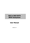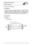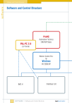
1
isel - PSPCI
User manual for stepper motor
control PSPCI Version 3
isel-automation GmbH & Co. KG
D-36466 Dermbach
Untere Röde 2
(036964)844
(036964)84510
About this manual:
The information, technical data and dimensions contained in this print have been up-to-date when
published. Any eventually existing misprints and mistakes cannot be excluded however. We are
thankful for any suggestion for improvement and indication of mistakes.
Please note that the used software- and hardware descriptions of each individual company are
generally subject to protection of trademarks and patent law.
All rights reserved. It is not permitted to reproduce or electronically process, duplicate or spread
any part of our prints in any way (print, copy etc.) without written permission of isel-automation.
Producer:
iselautomation GmbH & Co. KG
Bürgermeister-Ebert-Straße 40
D-36124 Eichenzell
Tel.: (06659) 981-0
Fax: (06659) 981-776
email: [email protected]
http://www.isel.com
In cooperation with TRIMETA Software GmbH.
Art.-Nr. 970326 BE852 10/2005
Contents
1
Introduction ....................................................................................................................... 1
1.1
2
3
3
Preamble..................................................................................................................... 1
Description of stepper motor PCI-card PSPCI............................................................... 2
2.1
System requirements .................................................................................................. 2
2.2
Assembly of control board in personal computer ...................................................... 2
Installation of drivers ........................................................................................................ 2
3.1
Technical Data............................................................................................................ 3
3.2
Connecting control board to power electronics.......................................................... 3
Initiation of machines with the adjusting software MtConfig....................................... 4
3.1
Introduction ................................................................................................................ 4
3.2
Starting the adjusting program ................................................................................... 4
3.3
The windows of MtConfig ......................................................................................... 5
3.3.1
The Main Window
5
3.3.2
The Toolbar
5
3.3.3
Select Parameters
6
3.3.4
Save and Close
6
3.3.5
The Coordinate Window
6
3.3.6
Inputs/Outputs
7
3.3.7
The Editor
7
3.3.8
Error-Status
7
3.4
Notes........................................................................................................................... 8
3.4.1
Referencing
8
3.4.2
Manual Jogging
8
3.5
Adjusting Parameters ................................................................................................. 9
3.5.1
Driver Parameters
9
3.5.1.1
Addresses ....................................................................................................... 9
3.5.1.2
Timer .............................................................................................................. 9
3.5.1.3
Current settings ............................................................................................ 10
3.5.1.4
Units ............................................................................................................. 11
3.5.1.5
Axes.............................................................................................................. 11
3.5.1.6
Range Limits ................................................................................................ 13
3.5.1.7
Manual Moving ............................................................................................ 13
3.5.2 Mtasc-Parameters
14
3.5.2.1
Feed Rate / Ramps........................................................................................ 14
3.5.2.2
Referencing .................................................................................................. 14
3.5.2.3
Inputs and Outputs ....................................................................................... 15
3.5.2.4
Extended Inputs / Outputs ............................................................................ 18
3.5.2.5
I/O- Actions.................................................................................................. 20
3.6
Configuration of axis direction ................................................................................ 21
3.6.1
Starting point
22
3.6.2
Adjusting the axis- and reference directions of gantry units
23
3.6.2.1
X-Axis .......................................................................................................... 23
3.6.2.2
Y-Axis .......................................................................................................... 25
3.6.2.3
Z-Axis........................................................................................................... 27
3.6.3 Adjusting the axis- and reference direction of flatbed units
29
3.6.3.1
X-Axis .......................................................................................................... 29
3.6.3.2
Y-Axis .......................................................................................................... 29
3.6.3.3
Z-Axis........................................................................................................... 30
3.7
Optimising................................................................................................................ 31
3.7.1
Procedure
31
3.7.2
Further details for the optimisation
32
3.7.3
The monitor window
33
isel-PSPCI V3 User Manual
1 Introduction
1.1 Preamble
iselautomation has been known for many years for its driving systems and CNC controls with
stepper motors. Stepper motors have become globally accepted in the small and medium
performance range.
They have practically become irreplaceable for driving systems with medium precision and
dynamic requirements. Stepper motor controls usually do not work with closed loops, so
expensive sensor- and evaluation units become dispensable. The result is a favourable costperformance ratio among an easy assembly and initiation.
For many years we have been offering systems basing on stepper motor controls, which have
been applied in many areas of production, automation, research and training.
The control PSPCI has been developed to continue this product line. It is a stepper motor
control, which was implemented as PCI plug-in card for PCs. It is possible to control up to 4
axes with the help of clock and direction signals.
This manual is to serve as support for initiating the control or machine and explain the most
important parameters and adjustments.
page - 1
isel-PSPCI V3 User Manual
2 Description of stepper motor PCI-card PSPCI
2.1 System requirements
Supported System Software
- Microsoft Win 2000 Pro, WinXP Home/Pro SP2
Minimum hardware- requirements of control computer
CPU
RAM
Graphic/Monitor
Pentium 4 or AMD at least 1GHz
128MB RAM
Graphics card with resolution 800 x 600 Pixel
Recommended hardware- requirements of control computer
CPU
RAM
Graphic/Monitor
Pentium 4 or AMD ≥ 1,5GHz
≥ 256 MB RAM
3D Graphics card with resolution 1024 x 768 Pixel or more
2.2 Assembly of control board in personal computer
For the assembly of the PCI-card PSPCI please follow the following steps:
1
Make sure there is one PCI slot unoccupied on your main board.
2
Remove the PC Casing to be able to reach the fixing screws for the PCI slot plates.
3
Now look for an unoccupied PCI bus slot.
4
Remove the according slot plate of the PCI slot.
5
Now plug the PSPCI stepper motor control into the slot. Make sure the card was plugged
in correctly!
6
Fix the card with screws.
7
Close the casing of your PC.
3 Installation of drivers
The PCI card PSPCI will automatically be identified when booting Windows for the first time
after the successful assembly of the card. The hardware installation assistant opens up. You
will be asked to name the data carrier or the path, where the driver can be found. You will
find the necessary driver on the ProNC/Remote installation- CD-Rom. Put a check mark to
the option CD-Rom. Click on Next. The assistant will now automatically search for the driver
on the CD-Rom and install it. Should the according driver not be found, you can search it
yourself with the help of Windows hardware manager on the CD-Rom.
page - 2
isel-PSPCI V3 User Manual
3.1 Technical Data
Control specific data
Number of axes
Inputs
Outputs
Analog output 0...V
4
3
Yes
3.2 Connecting control board to power electronics
A 37pole 1:1 cable is used as connecting cable between stepper motor control card PSPCI and
performance electronics. Connect the SubD37 plug with the SubD37 socket of the PCI card.
Connect the other end of this cable with the SubD37 socket to the designated plug on the
circuit board for the output stages.
Pin
1
2
3
4
5
6
7
8
9
10
11
12
13
14
15
16
17
18
19
Signal
Pulse X
Pulse Z
Pulse B
Direction Y
Direction A
+24VDC
User output 1
User output 3
Output Enable output stages
GND 24V
Reference switch /negative limit switch A
Reference switch /negative limit switch Z
Reference switch /negative limit switch Y
Reference switch /negative limit switch X
Reference switch B
Analogue GND
Input Power_ok
User input 2
Input Start button
page - 3
Pin
20
21
22
23
24
25
26
27
28
29
30
31
32
33
34
35
36
37
Signal
Pulse Y
Pulse A
Direction X
Direction Z
Direction B
+12VDC
User output 2
Output Spindle Start
-------------------------------positive limit switch A
positive limit switch Z
positive limit switch Y
positive limit switch X
positive limit switch B
Analogue output 0...10V
Input Stop button
User input 1
GND 24V
isel-PSPCI V3 User Manual
3 Initiation of machines with the adjusting software MtConfig
3.1 Introduction
MtConfig is a program to configure CNC-machines, which are navigated through Mtasc. The
program does not depend on any buttons or objects visible on the screen. It configures the
setting of machine and start parameters, especially for EdiTasc, ProNc and Remoteapplications.
From the main-window of MtConfig you have the following options
Configure your driver settings of the Mtdrv.ini file
Configure the startup-variables for Mtasc.dll files stored in the Mtasc.ini file.
Optimize and check the parameters of a running machine.
While working with MtConfig you can
display the current coordinates.
reference the axes.
display Inputs and Outputs.
issue motion commands from the editor and display values.
perform manual jogging with your keyboard.
Notice when using MtConfig:
Start MtConfig only out of a folder which contains the configuration-files and
MTasc.dll.
MtConfig uses MTasc. Never start MtConfig if any running program uses Mtasc.
3.2 Starting the adjusting program
To start the adjusting program MtConfig.exe, you have to click on the shortcut in the
startmenu after successfully installing and rebooting the computer.
Start
Programs
MtConfig PSPCI
MtConfig PSPCI
You can also start the adjusting program with the shortcut MtConfig PSPCI on your desktop.
Seite - 4
isel-PSPCI V3 User Manual
3.3 The windows of MtConfig
3.3.1
The Main Window
The main window shows on the left
at the top the toolbar along with driver information
in the middle the list for choosing parameters and the Input pane for parameters
at the bottom buttons for referencing and for saving your settings and closing the
program
On the right side you will find helpful information related to the parameter or button selected.
3.3.2
The Toolbar
The toolbar shows the following buttons (from left to right):
referencing of the axis
enable/disable watching of the range limits
Stop motion (F9)
display coordinates
display inputs and outputs
open the editor
The text field to the right contains driver information, the version of both the driver and the
MTasc.dll file.
Seite - 5
isel-PSPCI V3 User Manual
3.3.3
Select Parameters
You can choose between parameters of the
driver (Mtdrv.ini) and the MTasc-parameter
(MTasc.ini).
3.3.4
Save and Close
If you press "Save" all changes will overwrite the original settings. It is not possible to get the
original settings back after the new settings have been saved.
By pressing the "Close"-button MtConfig will be closed. You will be prompted for saving the
changes if there are any.
3.3.5
The Coordinate Window
The coordinate window shows the current coordinates of the machine. Mtasc is able to
manage several coordinate systems ("object coordinates"), which are based on a fixed system
of machine coordinates.
If you press Shift+F1 to Shift+F7 you can change between the following displays:
Shift+F1: Display Off
Shift+F2: Object Coordinates
Shift+F3: Machine Coordinates
Shift+F4: Speed
Shift+F5: Increments (Target)
Shift+F6: Increments (Actual)
Shift+F7: Trailing Offset (Incr.)
The shown speed is a digital size.
Seite - 6
isel-PSPCI V3 User Manual
3.3.6
Inputs/Outputs
This window shows the state of all
Inputs and Outputs defined by the
descriptors _InpDsc (inputs) and
_OutDsc (outputs).
The number of Input/Output lines may
be changed with the "+" and "-" buttons
respectively. More lines can be shown
using the scrollbar.
The button "Refresh continuously"
switches the continuous updating of the
values on or off.
3.3.7
The Editor
The editor is used to send commands to the MTascinterpreter. This makes it possible to test moving
instructions and to display or change the parameter
settings of the machine.
If you press Strg+Enter the following part of the
input will be executed:
the highlighted text, if there is any.
the line where the keyboard cursor is located
if there is no highlighted text.
The example on the right shows the input "? AxisLetters;" which is not highlighted.
Strg+Enter will therefore execute the whole line and show the result - XYZ - on the bottom of
the Editor.
3.3.8
Error-Status
If an errors occurs which is related to one axis the error
status will be displayed in a separate window.
The error-type will be shown along with the axis on
which the error occurred.
In the example the machine moved too far in negative xdirection. In this case the machine will have to be moved
manually in positive x-direction. It might be necessary to
reset the machine by pressing F9.
Seite - 7
isel-PSPCI V3 User Manual
Error
Range limit
Limit switch
Following error
TimeOut
Description
The machine has moved beyond the range limit. More details
see MTASC-Function MLIMIT in MTasc help file).
The machine has moved into a hardware limit switch in one
or more axis. The corrosponding hardware limit switch (+,-)
will be shown in the list.
The difference between desired and current position of at least
one axis has exceeded some internal limit.
Depends on the type of the controller. Only when
communicating with intelligent circuit boards.
In these cases the machine will stop immediately.
Error while using Programs (for Ex. Syntax error) will be shown in a separate window
along with name and path of the file and the line in which the error occurred.
3.4 Notes
3.4.1
Referencing
When referencing the axes (in order Z, X, Y, A, B ) will be moved towards one end to find
the appropriate zero position.
Before referencing the following values have to be assigned:
The output addresses for the axes
The moving direction of the axes (axes)
The direction used to reference (reference run)
The functionality of the reference switch
To check if the settings are correct use manual jogging.
3.4.2
Manual Jogging
To move the machine manually use the keyboard combinations Strg+Alt+Arrow or
AltGr+Arrow:
Alt + Ctrl + right arrow:
Alt + Ctrl + left arrow:
X- axis right
X- axis left
Alt + Ctrl + up arrow:
Alt + Ctrl + down arrow:
Y- axis backward
Y- axis forward
Alt + Ctrl + page up:
Alt + Ctrl + page down:
Z- axis up
Z- axis down
Alt + Ctrl + Pos1:
Alt + Ctrl + End:
A- axis plus
A- axis minus
Seite - 8
isel-PSPCI V3 User Manual
3.5 Adjusting Parameters
For the adjustment of parameters, there is a destinction between driver-parameters and
Mtasc parameters. These parameters will be explained in the following subchapters.
3.5.1
Driver Parameters
3.5.1.1 Addresses
The address-pane offers for each axis a field to insert a
"Data-output" address and to get a "Data-feedback". Not
each PC-card supports data feedback.
There should be “0000“ in every field.
3.5.1.2 Timer
The control cycle frequency indicates how
often the real-time loop is called per second. At
the same rate the position of the machine is
calculated.
The background frequency is used for example
to configure the cycle speed of the stepper
motors. The frequency must be much higher
than the control cycle frequency. If a driver is in use which does not need a background
frequency, enter 0.
"Delay" inserts extreme short delays into the background loop. The number entered in this
field is a loop counter, the generated delay depends on the hardware.
The pre-adjusted value for the cycle frequency is 1000 Hz, the value for the base
frequency is 100000 Hz using a step precision of a tenth step. These values should
not be changed.
Seite - 9
isel-PSPCI V3 User Manual
Speed limits
Speed limits limit the
requests which are sent to
the driver by MTasc.
When a request exceeds
the limit, the request will
be decreased accordingly.
If watching of following
errors is enabled all axes
will be stopped when the
should/is-difference is
reached by at least one axis. If an axis is blocked, the other axes only move with disabled
should/is-difference supervision.
The first input (X-axis) of maximum acceleration takes affect on all further axis. Other
inputs for residual axis will be ignored!
The values in the figure can be used for machines with ball screw spindles (pitch 4, 5, 10
mm).
For belt drive slides (e. g. perimeter of belt pulley is 70mm and gear 2:1) speed values of
800 mm/sec and accelerations of 2000-3000 mm/sec2 can be put in here.
The pre-adjusted value for “Actuate Trailing Error “ is 12100. The value for “Speed“ is
12000. The value for “Speed Jump“ is 4000.
These values should not be changed in any case!
3.5.1.3 Current settings
These adjustments are not of interest for this control board. They are only mentioned for the
sake of completeness.
Seite - 10
isel-PSPCI V3 User Manual
3.5.1.4 Units
Here you can configure the units in which the
speed and acceleration will be measured in.
There are predefined unit pairs such as "mm and
seconds", "cm and seconds" and "m and minutes".
You can also define your own unit by pressing
"user defined".
The figure on the right shows the standard
adjustment of area boundaries after the installation
of the driver software.
Enter the travel areas of the according axis into the according fields. You can either
experimentally ascertain the values by manual operation or use the traverse paths of the
data sheet, enclosed to the machine.
3.5.1.5 Axes
Here you can select the number of axes you want to use.
For each axis you indicate
• The axis letter
• Whether the axis is enabled or not.
• Alignment. The leading sign of "Move" indicates, in which direction the axis is to move
with increasing increments. These leading signs should be adjusted thusly that each axis
moves in manual jogging in the direction, you expect due to the keyboard-input
• The type of the axis; L/R: linear- or rotary axis
• Calibration. Indicate the distance one axis moves per increment. You can put in this value
directly or click on "Formula". You will then see an input window, in which you have the
opportunity to put in axis parameters.
• The reversal clearance correction is the number of increments, that has to be added to the
calculated reference value so the axis is on the expected position. To ascertain the reversal
clearance correction put in the value 0 and let the axis alternately go in both directions for
x increments. The value, at which the axis does not yet move, is the double reversal
clearance correction
• The number of axes.
By clicking on the button „Calc“ of the individual axis, you see a window in which you can
configure the axis. There is a distinction between linear- and rotary axes.
Seite - 11
isel-PSPCI V3 User Manual
Linear axes
You have to indicate the following parameters:
• pitch. You can find it on the enclosed data sheet or the label plate of the machine.
• steps per revolution. This value indicates the number of steps per revolution of the stepper
motor. The most common stepper motors make 200 full steps per revolution and have a
step angle of 1,8°.
• The factor for the resolution in increments/ full steps complies with the adjustment of the
step resolution of the used output stage. This factor can be changed by using the pulldown menu. The standard adjustment is tenth step. Keep this adjustment!
• Transmission or reduction ratio. These values have to be indicated if a gear is used. The
transmission/ reduction ratio is indicated through:
revolutions / output end (roe) : revolutions / motor end (rme)
Confirm the adjustments with “OK“.
Rotary-/Tilting axes
You have to indicate the following parameters:
• pitch. For tilting axes the adjustment value has to be 360°.
• steps per revolution. This value indicates the number of steps per revolution of the stepper
motor. The most common stepper motors make 200 full steps per revolution and have a
step angle of 1,8°.
• The factor for the resolution in increments/ full steps complies with the adjustment of the
step resolution of the used output stage. This factor can be changed by using the pulldown menu. The standard adjustment is tenth step. Keep this adjustment!
• Transmission or reduction ratio. These values have to be indicated if a gear is used. The
transmission/ reduction ratio is indicated through:
revolutions / output end (roe) : revolutions / motor end (rme)
Confirm the adjustments with “OK“.
Seite - 12
isel-PSPCI V3 User Manual
3.5.1.6 Range Limits
The range limits define the space in which
the machine is allowed to move. All values
have to be machine coordinates.
By pressing "Set" the current position of the
machine will be used as range limit.
The supervision of the range limit will be
deactivated while referencing. It is possible to activate/ deactivate it for each individual axis
by mark the check boxes on the right.
If the range limit watching is activated and the machine crosses the border it will stop moving
immediately and report the error in the error-status window. The machine has to be moved in
a permitted area to continue.
3.5.1.7 Manual Moving
On this pane you can set up all needed
values for manual moving.
"minimum distance" describes the distance
the axis will move by pressing a key once.
"V max" sets the maximum speed the axis
should be able to reach.
If you press a key more than once in a short time, the speed will increase in 20 steps until it
reaches V max.
Seite - 13
isel-PSPCI V3 User Manual
3.5.2
Mtasc-Parameters
3.5.2.1 Feed Rate / Ramps
On this pane you can set the speed and
acceleration which will be loaded when the
program starts.
The values can be changed, if needed, while
MTasc is running through programs or
MTasc-commands.
The "Angle tolerance" indicates until which angle the machine should work as if it were a
straight line. That means that until this angle no ramps will be calculated.
3.5.2.2 Referencing
On this pane you indicate the number of axes.
For each axis you have to indicate:
• The axis label.
• The direction of referencing.
• The distance between the referencing point and the „zero point“ of the axis.
• Whether referencing takes place or not.
• The number of the input for the reference switch.
• The referencing speed. “fast” is the speed to approach the reference switch. With
“slow” the axis is moved off the switch while referencing takes place.
For all axes you can select
• The sequence of the axes in which referencing takes place. To change this sequence,
highlight one of the axis letters and move it with the arrow keys to the right or to the
left.
The „Test“-button start the referencing for one axis.
Seite - 14
isel-PSPCI V3 User Manual
3.5.2.3 Inputs and Outputs
Fixed predefined inputs and outputs can be configured in this frame. In each case one byte
will be addressed. Please enter the hexadecimal offset of the basis-address in the addressfield.
The mask allows the selection of the bits which should be used for input and if they should be
inverted (-) or not (+). Click on the space above the diode to change the bits.
The inputs will only be read if ">" is selected. Each change of the output state will be written
immediately to the corresponding address. The gained values can be re-imported through
appropriate outputs by selecting ">".
The LED shows the status of the bits read:
• Deselected:
grey
• Input bit "1":
red
• Input bit "0":
blue
• Non inverted bits ("+") are shown normally.
• Inverted bits ("-") are shown in an inverted mode.
• Deselected bits (" ") are shown with shadowed colours.
Inputs
The PCI card inputs are already
pre-adjusted. The inputs no. 1 –
8 serve the evaluation of the
hardware limit switches.
The classification of the
limit switches must not be
changed!
Seite - 15
isel-PSPCI V3 User Manual
The inputs no. 9-11 are user
inputs. Using these inputs it is
possible to connect peripheral
devices, e. g. length callipers,
pressure monitors etc. to the
circuit board.
These user inputs have already
been pre-configured for certain
peripheral devices. Depending
on the machine type the
according inputs are either
assigned or not.
Standard Assignment:
No. 9 ... Stop button of operating unit.
No. 10 ... Start button of operating unit
No. 11 ... free user input
Before connecting new peripheral devices, please check whether the according input isn’t
already assigned.
Input No. 12 serves as Power_ok signal of the safety circuit module. It should not be changed
under any circumstances because it is being scanned periodically by the control to evaluate a
case of Emergency Stop. If there is no safety circuit module used, this input has to be
connected with +24VDC.
The indicated mode MMAP of inputs no. 1-12 is the so-called Memory-MAP mode. This
means that the inputs are not read directly through the hardware but through the two MAP
ports. Within these MAP ports the accordingly set “-“ above the LED affects the bit which is
to be switched.
Ports no. 13 and 14 are the so-called Memory- MAP ports. They each define an 8-bit port
with the physical addresses 0x00B0h and 0x00C0h.
The indicated mode PTI2 is the device type for the PSPCI card. You can find the description
of the assignment of the inputs with MMAP mode to the Memory-Map ports on tab I/O –
activities.
Seite - 16
isel-PSPCI V3 User Manual
The following chart shows the standard configuration of the inputs with information about
port numbers, addresses and bit numbers.
Map-Port Eing.-Nr. Typ Adresse
Bit-Maske
1
MMAP virtuell 0x01
2
MMAP virtuell 0x02
3
0
4
5
6
7
8
9
1
10
11
12
Bit-Nr.
Funktion
0
Limit Switch X 1
Limit Switch X +
MMAP virtuell 0x04
MMAP virtuell 0x08
2
Limit Switch Y -
3
Limit Switch Y+
MMAP virtuell 0x10
MMAP virtuell 0x20
4
Limit Switch Z -
5
Limit Switch Z +
MMAP virtuell 0x40
MMAP virtuell 0x80
6
Limit Switch A -
7
Limit Switch A +
MMAP virtuell 0x01
MMAP virtuell 0x02
8
Input Stop switch
9
Input Start switch
MMAP virtuell 0x04
MMAP virtuell 0x08
10
User Input
14
Input Power_ok
13
PTI2
14
PTI2
0x00B0 0xFF
0x00C0 0xFF
0-7
Map-Port 0
8 - 12 Map-Port 1
Changes should only be made regarding the description of the user inputs.
Changes of addresses and bits can result a faultily behaviour of the control.
Seite - 17
isel-PSPCI V3 User Manual
Outputs
Version 3 of the PSPCI card has
no user outputs. User outputs
must be realized with an external
I/O Modul.
Output no. 1 and 2 are
automatically set by the PCIcard. They serve to release the
brake of the axes (if existing)
and to “Enable” the power of the
amplifiers.
Output no. 4 is a virtual output, which used by the Mtasc driver. It serves the controlled
operation of the physical outputs Nor. 1, 2.
Output no. 3 defines the output descriptor for the analoque output port of the PSPCI card.
The software integration of the analoque port takes place with the involvement of the IO
modul DLL “IoMtasc.dll”.
The following chart shows the standard configuration of the outputs with information about
port numbers, addresses and bit numbers.
Nr. Typ Adresse
Inv. BitMaske
Bit-Maske
Funktion
1
PTI2
00A0h
0x01
0x00
Output Enable amplifiers
2
PTI2
00A0h
0x02
0x00
Output Brake
3
4
PTI2
PTI1
00D0h
0020h
0xFF
-------------------
0x00
----
Analogue output 0..10V (Port)
_ MotOn/Off (virtual output)
Changes should only be made regarding the description of the user ouputs.
Changes of addresses and bits can result faultily behaviour of the control.
3.5.2.4 Extended Inputs / Outputs
Extended Inputs
The expanded inputs serve the
transfer of the user inputs,
adjusted in MtConfig to ProNC/
Remote. Eight inputs comply
here with an extended input
(input port). The following
information has to be indicated:
• Type. Here has to be
indicated MMAP as type
of control. This can be
chosen by clicking on the
input field.
Seite - 18
isel-PSPCI V3 User Manual
•
•
•
Address of ports. In this case the adress is MAP-port adress.(Map 1).
With the mask you can indicate which bits will be used for the input and whether the
bits should be inverted (-) or not (+). The inputs will only be read if ">" is activated.
Each change of the initial state is immediately written to the complying address.
The number of expanded inputs can be chosen between 0 and 6 and is saved in the file
Mtasc.ini under the key "n=". If "n=-1" is written in the according section of
Mtasc.ini, the expanded inputs are not displayed.
The light emitting diodes indicate the condition of the imported bit string.
• Not imported:
grey
• Input "1":
red
• Input "0":
blue
• Directly imported bits ("+") are displayed normally.
• Inverted bits ("-") are displayed inverted.
• Faded out bits (" ") are displayed as un-logged.
The following chart shows the pre-adjusted configuration of the expanded inputs.
Port No. 1 with address 00C0h, Map-Port 1 (Map1) with device type PTI2
Bit / Addr.
Application
Logical Port
Plug
1 / 0x01h
Input Stop button
I1.1
X21
2 / 0x02h
Input Start button
I2.2
X27
3 / 0x04h
User Input
6 / 0x20h
Input Power_ok
I2.3
-----------------------------
X28
X29
Mask of both ports
Port No.
1
Type
PTI2
Adress
000Bh
Bit-Mask
0x07
Map-Port
1 (Map1)
The mask of the expanded inpu serve the signalling of the conditions in ProNC/ Remote. The
extended input are displayed as a super-imposed bit string within the I/O direct access
window. Only those inputs are displayed correctly which have been marked (provided with +
or -) with the mask of the extended input.
Changes should not be made here!
Extended Output
In version 3 of the PSPCI you don’t have to configure a extended output port because no
outputs are available.
Seite - 19
isel-PSPCI V3 User Manual
3.5.2.5 I/O- Actions
Please read the following descriptions thoroughly. A change of the parameters
can result in a dysfunction of the PSPCI card and thus your machine.
You should not change the pre-adjusted values!!!!
In I/O-activities you can define and adjust the monitoring of hardware limit switches.
In other words, the assignment of the physical input addresses of the card to the „virtual”
inputs, which signal the condition of the limit switch if taking place here.
To every MAP-Port
there is a fixed index, a
start bit and a number of
bits assigned. In this case
the MAP ports with the
physical
addresses
0x00B0h and 0x00C0h
(no.1
AdrB0
no.2
Adr.C0) are defined with
the input descriptors no.
13 and 14. The inputs
defined on these MAP ports reflect the current condition of the physical inputs of the PSPCI
card. The six check boxes serve the configuration of the cache, writing and reading direction.
Only the first check box on the left is of interest. By checking the box the MAP port is
activated.
The entries from no. 3 to no. 10 define the actual assignment of the physical inputs to the
MAP-Ports. For each limit switch (limit switch -, limit switch +) the input descriptor no.,
descriptor bit no., map index, map bit no. and the number of bits to be operated have to be
indicated here. The configuration has already been adjusted for five axes. You should not
change the values. Only the first check box on the left with the complying entry is of interest.
By deactivating the check boxes of no. 3 – 10 you can deactivate the monitoring of the
hardware limit switches.
In this configuration the
two hardware limit
switches of the y-axis
are deactivated for
example.
Seite - 20
isel-PSPCI V3 User Manual
3.6 Configuration of axis direction
In this chapter the configuration of the X-, Y- and Z axis direction will be explained. Due to
the different constructions and arrangements of the axis on machines and systems, the
standard adjustments for the axis direction have to be changed.
As a basic principle two different types of machines have to be distinguished:
Gantry units ( e. g. EuroMod P Series)
The machine table (Y axis) carries the clamping plate for
the work piece. It moves in positive Y direction from the
tool tip when moving towards the operator.
Flatbed units (e.g. EuroMod F Series, FlatCom
Series, OverHead Series)
The clamping area for the work piece is solidly fixed on the
machine frame. A Y-movement of the tool in positive
direction (+Y) goes away from the operator.
For both types the axis direction has to be considered regarding the tool tip, so
the coordinate system adds up to a „right-system“. (right-hand-rule).
Seite - 21
isel-PSPCI V3 User Manual
Assignment of axis directions
The assignment of the moving axes regarding the operating position is:
For flatbed units
X-axis = transverse axis (+X to the right; -X to the left)
Y-axis = longitudinal axis (+Y away from operator; -Y towards operator)
Z-axis = lifting axis (+Z upward; -Z downward)
For gantry units
X-axis = transverse axis (+X to the right; -X to the left)
Y-axis = longitudinal axis (-Y away from operator; +Y towards operator)
Z-axis = lifting axis (+Z upward; -Z downward)
The procedure to initiate the axis is explained in the subchapters of each machine type.
3.6.1
Starting point
•
Please check all adjustments of drivers and Mtasc parameters of the previous
chapters.
•
Check if the ports on the circuit board are correctly:
Are the motor cables plugged in correctly?
Are the signal cables for limit switches and brake plugged in correctly?
Are the signal cables of the SK module plugged in correctly?
Are the inputs and outputs connected according to the standard assignment?
•
Check the power supply of limit switches and circuit boards:
Do the LED of the output stages glow?
Is the power button pushed?
Please use the delivered documentation of your machine to do the inspection. (circuit
diagram, manual etc.)
Seite - 22
isel-PSPCI V3 User Manual
3.6.2
Adjusting the axis- and reference directions of gantry units
Follow the instructions for the initiation of the individual axes.
3.6.2.1 X-Axis
1) Click on the button „I/O – Actions“ in MtConfig. Deactivate the hardware limit switch of
the X axis by removing the check in the first check box of the left. (also see chapter:
3.5.2.5 I/O- Actions)
2) Now move to the field „Axes“ within the driver parameters. Check the alignment by
manually moving the X axis. Therefore use the short cut Alt + Ctrl + left arrow and Alt
+ Ctrl + right arrow
The following picture shows the correct axis alignment.
In case the X axis does not move as shown in the picture, please change the direction of
the axis by pushing the button
for the direction of the axis.
Click the button “Save“ in the main window of MtConfig to save the new adjustments.
Check the alignment again.
Seite - 23
isel-PSPCI V3 User Manual
Now the referencing direction of the axis has to be adjusted. Make sure the axis is not in
a limit switch position. To do this you have to go to the adjusting field “referencing”.
The hardware limit switches of each axis are fixed and should not be changed by means of
the configuration program.
Please take a look at the window for the inputs and outputs. The first two entries are:
Both limit switches are plugged in correctly if the left LED next to the entry is blue
in inactive condition.
3) Move the X-axis by pushing Alt + Ctrl + left arrow slowly to the left in the direction of
the limit switch. -. While moving, watch the display of the inputs, in particular input no.
1 limit switch X -.Now move until the blue LED for limit switch X- goes out.
Should this not be the case and the LED for limit switch X+ goes out instead, you have to
exchange the wiring of the signal cables for the limit switches on the circuit board. This
means you have to exchange limit switch X- and X+ for the X axis.
As soon as the LED for limit switch X- is out, please move to the opposite direction away
from the limit switch. Now the LED has to be blue again.
Repeat this step again for the other limit switch. Move the axis by pushing Alt + Ctrl +
right arrow. Also check the functioning of the limit switch.
4) After you have checked both hardware limit switches, you have to adjust the referencing
direction. For this purpose you have to move the axis to the middle of the traverse range.
Click on “Test“ all the way on the right within the entry field of the according axis. Watch
the movement of the axis. If the axis moves to the left in direction of limit switch X-, the
referencing direction is adjusted correctly. Now you have to check the reference input,
that is to be used for referencing. In this case input no. 1 limit switch X- serves as
reference switch. (see picture above)
If the axis does not move in the right direction, please cancel the referencing of axis by
pushing F9 or the button
. Now invert the referencing direction by pushing the
button . Save the adjustments.
Repeat the referencing to check the adjustments again.
1) If the referencing was successfully completed, save all adjustments. Activate the hardware
limit switch monitoring for the axis within the entry field I/O-activities by checking the
first check box. (see also chapter: 3.5.2.5 I/O- Actions). Save the adjustments again.
You can now configure the next axis.
Seite - 24
isel-PSPCI V3 User Manual
3.6.2.2 Y-Axis
1) Click on the button „I/O – Actions“ in MtConfig. Deactivate the hardware limit switch of
the Y axis by removing the check in the first check box of the left. (also see chapter:
3.5.2.5 I/O- Actions)
2) Now move to the field „Axes“ within the driver parameters. Check the alignment by
manually moving the Y axis. For this use the short cut Alt + Ctrl + up arrow and Alt +
Ctrl + down arrow.
The following picture shows the correct axis alignment.
In case the Y axis does not move as shown in the picture, please change the direction of
the axis by pushing the button
for the direction of the axis.
Click the button “Save“ in the main window of MtConfig to save the new adjustments.
Check the alignment again.
Seite - 25
isel-PSPCI V3 User Manual
Now the referencing direction of the axis has to be adjusted. Make sure the axis is not in
a limit switch position. To do this you have to go to the adjusting field “referencing”.
The hardware limit switches of each axis are fixed and should not be changed by means of
the configuration program.
Please take a look at the window for the inputs and outputs. Entry no. 3 and 4 is:
Both limit switches are plugged in correctly if the left LED next to the entry is blue
in inactive condition.
3) Move the Y-axis by pushing Alt + Ctrl + up arrow slowly forwardly towards you in the
direction of the limit switch. -. While moving, watch the display of the inputs, in
particular input no. 4 limit switch Y +.Now move until the blue LED for limit switch
Y+ goes out.
Should this not be the case and the LED for limit switch Y- goes out instead, you have to
exchange the wiring of the signal cables for the limit switches on the circuit board. This
means you have to exchange limit switch Y+ and Y- for the Y axis.
As soon as the LED for limit switch Y+ is out, please move to the opposite direction away
from the limit switch. Now the LED has to be blue again.
Repeat this step again for the other limit switch. Move the axis by pushing Alt + Ctrl +
+ down arrow. Also check the functioning of the limit switch.
After you have checked both hardware limit switches, you have to adjust the referencing
direction. For this purpose you have to move the axis to the middle of the traverse range.
Click on “Test“ all the way on the right within the entry field of the according axis. Watch
the movement of the axis. If the axis moves forwardly towards you in direction of limit
switch Y+, the referencing direction is adjusted correctly. Now you have to check the
reference input, that is to be used for referencing. In this case input no. 4 limit switch
Y+ serves as reference switch. (see picture above)
If the axis does not move in the right direction, please cancel the referencing of axis by
pushing F9 or the button
. Now invert the referencing direction by pushing the
button . Save the adjustments.
Repeat the referencing to check the adjustments again.
4) If the referencing was successfully completed, save all adjustments. Activate the hardware
limit switch monitoring for the axis within the entry field I/O-activities by checking the
first check box. (see also chapter: 3.5.2.5 I/O- Actions). Save the adjustments again.
You can now configure the next axis.
Seite - 26
isel-PSPCI V3 User Manual
3.6.2.3 Z-Axis
1) Click on the button „I/O – Activities“ in MtConfig. Deactivate the hardware limit switch
of the Z axis by removing the check in the first check box of the left. (also see chapter:
3.5.2.5 I/O- Acti)
2) Now move to the field „Axes“ within the driver parameters. Check the alignment by
manually moving the Z axis. For this use the short cut Alt + Ctrl + page up and Alt +
Ctrl + page down
The following picture shows the correct axis alignment.
In case the Z axis does not move as shown in the picture, please change the direction of
the axis by pushing the button
for the direction of the axis.
Click the button “Save“ in the main window of MtConfig to save the new adjustments.
Check the alignment again.
Seite - 27
isel-PSPCI V3 User Manual
Now the referencing direction of the axis has to be adjusted. Make sure the axis is not in
a limit switch position. To do this you have to go to the adjusting field “referencing”.
The hardware limit switches of each axis are fixed and should not be changed by means of
the configuration program. Please take a look at the window for the inputs and outputs.
Entry no. 5 and 6 is:
Both limit switches are plugged in correctly if the left LED next to the entry is blue
in inactive condition.
3) Move the Z-axis by pushing Alt + Ctrl + page up slowly up in the direction of the limit
switch. +. While moving, watch the display of the inputs, in particular input no. 6 limit
switch Z+. Now move until the blue LED for limit switch Z+ goes out.
Should this not be the case and the LED for limit switch Z- goes out instead, you have to
exchange the wiring of the signal cables for the limit switches on the circuit board. This
means you have to exchange limit switch Z- and Z+ for the Z axis.
As soon as the LED for limit switch Z+ is out, please move to the opposite direction away
from the limit switch. Now the LED has to be blue again.
Repeat this step again for the other limit switch. Move the axis by pushing Alt + Ctrl +
page down. Also check the functioning of the limit switch.
4) After you have checked both hardware limit switches, you have to adjust the referencing
direction. For this purpose you have to move the axis to the middle of the traverse range.
Click on “Test“ all the way on the right within the entry field of the according axis. Watch
the movement of the axis. If the axis moves up in direction of limit switch Z+, the
referencing direction is adjusted correctly. Now you have to check the reference input,
that is to be used for referencing. In this case input no. 6 limit switch Z+ serves as
reference switch. (see picture above)
If the axis does not move in the right direction, please cancel the referencing of axis by
pushing F9 or the button
. Now invert the referencing direction by pushing the
button . Save the adjustments.
Repeat the referencing to check the adjustments again.
5) If the referencing was successfully completed, save all adjustments. Activate the hardware
limit switch monitoring for the axis within the entry field I/O-activities by checking the
first check box. (see also chapter: 3.5.2.5 I/O- Actions). Save the adjustments again.
Seite - 28
isel-PSPCI V3 User Manual
3.6.3
Adjusting the axis- and reference direction of flatbed units
Follow the instructions for the initiation of the individual axes.
3.6.3.1 X-Axis
Please read the initiating instruction of the X-axis for gantry units and follow the steps. (see
chapter 3.6.2.1 X-Axis)
3.6.3.2 Y-Axis
1) Click on the button „I/O – Activities“ in MtConfig. Deactivate the hardware limit switch
of the Y axis by removing the check in the first check box of the left. (also see chapter:
3.5.2.5 I/O- Actions)
2) Now move to the field „Axes“ within the driver parameters. Check the alignment by
manually moving the Y axis. For this use the short cut Alt + Ctrl + up arrow and Alt +
Ctrl + down arrow.
The following picture shows the correct axis alignment.
In case the Y axis does not move as shown in the picture, please change the direction of
the axis by pushing the button
for the direction of the axis. Click the button “Save“ in
the main window of MtConfig to save the new adjustments. Check the alignment again.
Seite - 29
isel-PSPCI V3 User Manual
Now the referencing direction of the axis has to be adjusted. Make sure the axis is not in
a limit switch position. To do this you have to go to the adjusting field “referencing”.
The hardware limit switches of each axis are fixed and should not be changed by means of
the configuration program.
Please take a look at the window for the inputs and outputs. Entry no. 3 and 4 is:
Both limit switches are plugged in correctly if the left LED next to the entry is blue
in inactive condition.
6) Move the Y-axis by pushing Alt + Ctrl + up arrow slowly forwardly towards you in the
direction of the limit switch. -. While moving, watch the display of the inputs, in
particular input no. 4 limit switch Y +.Now move until the blue LED for limit switch
Y+ goes out.
Should this not be the case and the LED for limit switch Y- goes out instead, you have to
exchange the wiring of the signal cables for the limit switches on the circuit board. This
means you have to exchange limit switch Y+ and Y- for the Y axis.
As soon as the LED for limit switch Y+ is out, please move to the opposite direction away
from the limit switch. Now the LED has to be blue again.
Repeat this step again for the other limit switch. Move the axis by pushing Alt + Ctrl +
down arrow. Also check the functioning of the limit switch.
After you have checked both hardware limit switches, you have to adjust the referencing
direction. For this purpose you have to move the axis to the middle of the traverse range.
Click on “Test“ all the way on the right within the entry field of the according axis. Watch
the movement of the axis. If the axis moves forwardly towards you in direction of limit
switch Y+, the referencing direction is adjusted correctly. Now you have to check the
reference input, that is to be used for referencing. In this case input no. 4 limit switch
Y+ serves as reference switch. (see picture above)
If the axis does not move in the right direction, please cancel the referencing of axis by
pushing F9 or the button
. Now invert the referencing direction by pushing the
button . Save the adjustments.
Repeat the referencing to check the adjustments again.
7) If the referencing was successfully completed, save all adjustments. Activate the hardware
limit switch monitoring for the axis within the entry field I/O-activities by checking the
first check box. (see also chapter: 3.5.2.5 I/O- Actions). Save the adjustments again.
You can now configure the next axis.
3.6.3.3 Z-Axis
Please read the initiating instruction of the Z-axis for gantry units and follow the steps. (see
chapter 3.6.2.1 Z-Axis)
Seite - 30
isel-PSPCI V3 User Manual
3.7 Optimising
Within the optimising window the parameters for the motor control are indicated and
optimised.
The axes can be moved separately or coupled within a given travel distance, while the
parameters are being adjusted. The monitoring window always opens together with the
optimising window. Within the monitoring window the track data of the moving axes are
graphically displayed.
3.7.1
Procedure
1
2
3
4
5
6
7
8
Choose the axis which is to be optimised (1).
Adjust the travel range (2).
Move to the position which is to be the 0 position, if necessary do so by manual jogging.
If necessary reset the current position of the machine with "=0" (3).
Adjust the speed with the slide control. (4). The speed can also be changed while moving.
If necessary, adjust the acceleration. (5)
Start the movement by clicking on "MOVE" (6).
You can change the parameters during the moving process. To do so, click into the field,
whose value you want to change and enter a new value or use the slide control. (8).
9 If necessary, adapt the multipliers accordingly (7).
10 By clicking on "Circle" (9) (not available in automatic mode) the machine is forced to
make a circle for two of the three axes X, Y and Z. You chose the axes within the column
"Move".
Seite - 31
isel-PSPCI V3 User Manual
11 A change of the travel range during the moving process affects later because the moving
command cache (10) can still contain moving commands. Empty this cache by clicking
on "RESET", this way the cache is emptied and the motor control reset.
12 You save the newly adjusted values with "Save". If values have been changed, you will
be asked whether the new values are to be saved when leaving the optimising window.
3.7.2
Further details for the optimisation
If the parameters have to be completely recalibrated, it is useful to reset the D- and I values (if
available) and increase the P values until the machine runs with a „fixed“ noise without
becoming loud.
After that the D-controller will be raised until the target/actual deviation displayed in the
monitoring window are minimal. This process can be automatically supported by clicking on
„AUTO“
If both values are adjusted, the I-controller (if available) can be used for fine tuning. The I
value is only sensible if using a closed loop. It is usually used for axes with high mechanical
friction.
Seite - 32
isel-PSPCI V3 User Manual
3.7.3
The monitor window
Within the monitoring window either the target/actual deviations or optionally the speeds of
up to two axes are graphically displayed at the same time.
The display is two coloured: Green is for movement in positive direction and red for
movement in negative direction of the individual axis. If the shown values are above the
horizontal line the current machine velocity is lower than the target velocity.
Adaptations:
1)
2)
3)
4)
Select the axes with the Axis selection (1).
Change the maximum value of the scale with the scale factor (2).
Select between bar and point display with the display selection (3).
If you stop the display, (4), another button "Details" appears (not visible here), and a
block of the upper line is marked by a case.
5) The contents of this case is displayed with a tenfold resolution in the lower line. The detail
block can be adapted by moving the case with the mouse.
Seite - 33