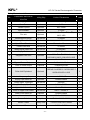
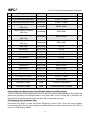
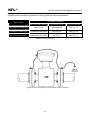
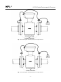
1
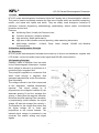
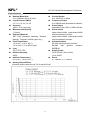
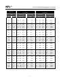
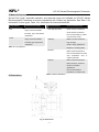
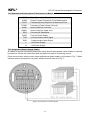
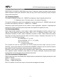
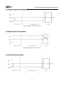
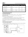
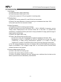
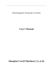
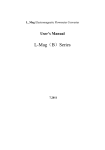
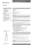
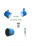
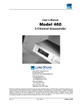
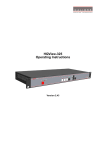
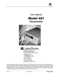
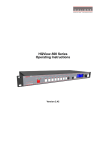
KFL® KFL-DC Serials Electromagnetic Flowmeters User Manual KFL® KFL-DC Series Electromagnetic Flowmeters CONTENTS 1. Profile…………………………………………………………………………………………………1 2. Structure and Operating Principle…………………………………………………………………1 3. Specification……………………………………………………………………………………2 4. Model and Suffix Code………………………………………………………………………………5 5. Material Selection…………….……………………………………………………………………6 6. Dimensions……………………………………………………………………………………...6 7. Connection and Operation of Converter…………………………………………………9 8. Setting Parameters……………………………………………………………………….16 9. Recording Time When Power Turn-Off (with Power Turn-Off Function)………………..……19 10. Recording Gross of hour…………………………………………………………............…20 11. Infrared Telecontrol Function Keys……………………..………………………………20 12. Alarm Info rmation………………………………………………………………………20 13. I n s ta l l a t i o n … … … … … … … … … … … … … … … … … … … … … … … … … … … … … . . 2 0 14. Troubleshooting……………………………………………………………………………………26 KFL® KFL-DC Series Electromagnetic Flowmeter 1. Profile KFL-DC series electromagnetic flowmeters follow the Faraday law of electromagnetic induction. They can be used to accurately measure the flow rate of liquids which are electrical conducting, caustic, and mixed with liquids and solids. They are widely used throughout industries of petroleum, chemical engineering, pharmacology, papermaking, electric power, environmental protection and so forth. Features: No Moving Parts, Virtually No Pressure Loss; Corrosion protection, abrasion resistant; High accuracy, Stable performance; High level of anti-vibration and anti-jamming, wide measuring dimensions. Multi-Output Interface : 4~20mA, Pulse, Alarm Outputs, RS-485 and Modbus Communication. 2. Structure and Operation Principle 2.1. Structure KFL-DC series electromagnetic flowmeters are made up of sensor and transducer, together with LCD screen, current and pulse output, alarm signal and RS-485 communication. 2.2 Operating Principle Faraday’s Laws of Induction form the basis for the electromagnetic flowmeters. It states that a voltage is induced in a conductor as it moves through a magnetic field. This principle is applied to a conductive fluid which flows through a magnetic field generated perpendicular to the flow direction (see Schematic). The voltage induced in the fluid is measured at two electrodes, installed diametrically opposed. This signal voltage UE is proportional to the magnetic induction B, the electrode spacing D and the average flow velocity v. Noting that the magnetic induction B and the electrode spacing D are constants, a proportionality exists between the signal voltage UE and the average flow velocity v. The equation for the volume flow shows that the signal voltage UE is linear and proportional to the volume flowrate. The induced signal voltage is processed in the converter into scaled, analog and digital signals. Fig. 1: Electromagnetic Flowmeter Schematic -1- KFL® KFL-DC Series Electromagnetic Flowmeter 3. Specifications Nominal Meter Size 10 to 1000mm (3/8 to 40 inch) Liquid Pressure (MPa) 1.0, 1.6, 2.5, 4.0, 16, 25 Accuracy ±0.5%, ±1% (upon req.) Minimum Conductivity >5μs/cm Electrode Material SST 316L (standard), Hastelloy, Tantalun, titanium, Tungsten Carbide (upon req.) Fluid Temperature -25 to 65℃ (-13 to 149℉) -25 to 140℃(-13 to 284℉)(opt.) Liner PO, PTFE, PFA Relative Humidity ≤85% Ambient Temperature -30 to 60℃ (-22 to 140℉) Analog Output Effects Same as pulse output plus ±0.1% of rate ±0.01mA Fig. 2: Analog Output Effects -2- Current Output 0 to 10mA or 4 to 20mA Frequency Output 0 to 5000Hz with photoelectric isolation Pulse Output Adjustable from 0.001 to 1000 Ltr/Pulse Alarm Output Upper Alarm-ALMH, Lower Alarm-ALML with photoelectric isolation Upper Alarm-ALMH, Lower Alarm-ALML with photoelectric isolation Communications RS-232 without galvanic isolation RS-485 with galvanic isolation, MODBUS. Supply Power 85 to 250VAC (45 to 63Hz) 16 to 36VDC Power S<10W/AC, S<7.5W/DC KFL® KFL-DC Series Electromagnetic Flowmeter Flow Ranges and Meter Sizes Meter Size DN Min. Flow Range Max. Flow Range Flow Velocity Flow Velocity 0 to 0.5 m/s 0 to 1.64 ft/s 3 Inch 10 3/8 0 to 2 l/min 0 to 0.52 0 to 40 15 1/2 0 to 5 l/min 0 to 1.32 0 to 100 20 3/4 0 to 7.5 l/min 0 to 1.98 0 to 25 1 0 to 10 l/min 0 to 2.64 32 1 1/4 0 to 20 l/min 0 to 40 1 1/2 0 to 30 l/min 50 2 0 to 3 m /h 3 6 3 m /h 3 2 1/2 0 to 0 to 32.81 ft/s 3 mm 65 l/min, m /h 0 to 10 m/s gpm l/min, m /h gpm 0 to 11.88 l/min 0 to 26.41 150 l/min 0 to 39.62 0 to 200 l/min 0 to 52.83 5.28 0 to 400 l/min 0 to 105.66 0 to 7.92 0 to 600 l/min 0 to 158.50 0 to 13 0 to 60 0 to 26 0 to l/min 3 m /h 0 to 264 120 3 m /h 0 to 528 3 80 3 0 to 9 m /h 0 to 39 0 to 180 m /h 0 to 792 100 4 0 to 12 m /h 3 0 to 52 0 to 240 m /h 3 0 to 1056 21 3 m /h 420 3 m /h 0 to 1849 3 3 0 to 2641 125 5 0 to 0 to 92 0 to 150 6 0 to 30 m /h 0 to 132 0 to 600 200 8 0 to 54 m /h 3 0 to 237 0 to 1080 m /h 3 0 to 4755 90 3 1800 3 m /h 0 to 7925 3 250 10 0 to m /h 3 0 to 396 0 to m /h 300 12 0 to 120 m /h 0 to 528 0 to 2400 m /h 0 to 10566 350 14 0 to 165 m /h 3 0 to 726 0 to 3300 m /h 3 0 to 14529 225 3 m /h 4500 3 m /h 0 to 19812 3 3 400 16 0 to 0 to 990 0 to 450 18 0 to 300 m /h 0 to 1320 0 to 6000 m /h 0 to 26417 500 20 0 to 330 m /h 3 0 to 1452 0 to 6600 m /h 3 0 to 29058 480 3 m /h 9600 3 m /h 0 to 42267 3 3 600 24 0 to 0 to 2113 0 to 700 28 0 to 660 m /h 0 to 2905 0 to 13200 m /h 0 to 59117 800 32 0 to 900 m /h 3 0 to 3962 0 to 18000 m /h 3 0 to 79251 24000 3 m /h 0 to 105668 27000 3 0 to 118877 900 1000 36 40 0 to 0 to 3 1200 m /h 1350 3 m /h 0 to 0 to 5283 5943 0 to 0 to Table. 1: Flow Ranges and Meter Size -3- m /h KFL® KFL-DC Series Electromagnetic Flowmeter Flowrate Nomograph Fig. 2: Flowrate Nomograph DN1 to DN 100 (3/8” to 4”) Fig. 3: Flowrate Nomograph DN 125 to 1000 (5” to 40”) Flowrate Nomographs Example: The volume flowrate is a function of the flow velocity and Flowrate = 7 m3/h [30.82 gpm] (Maximum value = range the flowme-ter size. The Flowrate Nomographs, Fig. 2: and end value). Suitable are flowmeter sizes DN 20 to DN Fig. 3: indicate the flowrate range for a specific flowmeter 65 [3/4” to 2-/12”] for a flow velocity between 0.5 and 10 m/s [1.64 and 32.81 ft/s]. size and which flowmeter sizes are suitable for a specific flowrate. -4- KFL® KFL-DC Series Electromagnetic Flowmeter 4. Model and Sufix Code Model KFL-DC- Meter Size Suffix Code Description …… ………………………………... Electromagnetic Flowmeter 0010 ………………………….…..... Nominal Size 10 mm (3/8in.) 0015 ……………………………...... Nominal Size 15 mm (1/2in.) … ……………………………...... … 0200 …………………….………..... Nominal Size 200 mm (8in.) … ……………………….............. … 1000 ………………………….…..... Nominal Size 1000 (40in.) M………………………...….... Integral Type for General Purpose Construction N…………………………….... Integral Type for Explosion Proof D…………………………….... Remote Type for General Purpose E…………………………….... Remote Type for Explosion Proof S………………………... Stainless Steel 304 L………………...…..….. Stainless Steel 316L Electrode Material H…………….………….. Hastelloy (Note 1) T………………….…….. Tantalum Lining (Note 1) V………………….…….. Titanium W…………….…………. Tungsten Carbide P………………...... PO T…………............. PTFE A………….……..... Output Signal Earth Ring Liquid Pressure (MPa) PFA -L…………… Local (non signal output) -D…………… 0-10mA -C…………… 4-20mA -P…………… Pulse -F…………… Frequency -R…………… RS-232 -S…………… RS-485 -M…………... MODBUS N……… Non Earth Ring E…….... Earth Ring -1.0 PN. -1.0, -2.0, -2.5, -16, -25 Note 1: Users must consider the characteristics of selected wetted parts material and the influence of process fluids. The use of inappropriate materials can result in the leakage of corrosive process fluids and cause injury to personnel and/or damage to plant facilities. It is also possible that the instrument itself can be damaged and that fragments from the instrument can contaminate the user's process fluids. Be very careful with highly corrosive process fluids such as hydrochloric acid, sulfuric acid, hydrogen sulfide, sodium hypochlorite, and high-temperature steam (150°C [302°F] or above). Contact KFL for detailed information of the wetted parts material. -5- KFL® KFL-DC Series Electromagnetic Flowmeter 5. Material Selection Several liner types, electrode materials, and electrode types are available on KFL-DC Serials Electromagnetic Flowmeters to ensure compatibility with virtually any application. See Table. 2 for information on liner types, Table. 3 for information on electrode materials. Lining Material PFA General Characteristics Highly chemical-resistant Electrode Material General Characteristics 316L Stainless Steel Good corrosion resistance Good abrasion resistance Excellent high temperature Not recommended for sulfuric capabilities PTFE or hydrochloric acids Highly chemical-resistant Hastelloy Excellent high temperature Better corrosion resistance High strength capabilities Good in slurry applications Table. 2: Lining Material Effective in oxidizing fluids Tantalum Better chemical resistance Not recommended for fluosilic acid, hydrofluoric acid, sodium hydroxide Titanium Better chemical resistance Better abrasion resistance Good for sea water applications Not recommended for hydrofluoric or sulfuric acid 6. Dimensions Table. 3: Electrode Material Fig. 4: Dimensions -6- or KFL® Pressure Rating (ANSI CL) 150 300 KFL-DC Series Electromagnetic Flowmeter Meter Size (DN) Main Extemal and Connecting Dimensions(mm) in mm L D D1 D2 b z-d 1/2 15 200 89 60.5 35 11.2 4-16 3/4 20 200 98 70 43 11.2 4-16 1 25 200 108 79.5 51 11.2 4-16 1 1 /4 32 200 117 89 64 13 4-15 1 1 /2 40 200 127 98.5 73 14.3 4-16 2 50 200 152 120.5 92 15.9 4-19 1 2 /2 65 200 178 139.5 105 17.5 4-19 3 80 250 190 152.5 127 19.1 4-19 4 100 250 229 190.5 157 23.9 8-19 5 125 250 254 216 186 23.9 8-22 6 150 300 279 241.5 216 25.4 8-22 8 200 350 343 298 270 28.6 8-22 10 250 400 406 362 324 30.2 12-25 12 300 400 482.6 431.5 381 31.8 12-25 14 350 400 533 476 413 35 12-29 16 400 450 597 539.5 470 36.6 16.29 20 500 450 699 635 584 42.9 20-32 24 600 600 813 749.5 692 47.7 20-35 30 750 750 985 914 857 74.5 28-35 36 9000 900 1170 1086 1022 90.5 32-41 40 1000 1000 1289 1200 1124 90.5 36-41 1/2 15 200 95 66.5 35 14.2 4-16 3/4 20 200 117 82.5 43 15.9 4-19 1 25 200 124 89 51 17.5 4-19 1 1 /4 32 200 133 98.5 64 19 4-19 1 1 /2 40 200 156 114.5 73 20.7 4-22 2 50 200 165 127 92 22.3 8-19 1 2 /2 65 200 190 149 105 25.4 8-22 3 80 250 210 168.5 127 28.6 8-22 4 100 250 254 200 157 31.8 8-22 5 125 250 279 235 186 35 8-22 6 150 300 318 270 216 36.5 12-22 8 200 350 381 330 270 41.3 12-25 10 250 400 445 387.5 324 47.7 16-29 -7- KFL® 600 900 1500 2500 KFL-DC Series Electromagnetic Flowmeter 12 300 400 520.8 451 381 50.8 16-32 14 350 400 584.2 514.5 413 53.8 20-32 16 400 450 647.8 571.5 470 57.2 20-35 20 500 450 774.8 685.8 584 63.5 24-35 1/2 15 225 95 66.5 35 14.3 4-16 3/4 20 225 117 82.5 43 15.9 4-19 1 25 225 124 89 51 17.5 4-19 1 1 /4 32 225 133 98.5 64 21 4-19 1 1 /2 40 225 156 114.5 73 22.3 4-22 2 50 225 165 127 92 25.4 8-19 1 2 /2 65 222 190.5 149.5 120.5 28.6 8-22 3 80 250 210 168 127 31.8 8-22 4 100 250 273 216 157.2 38 8-25 1/2 15 225 121 82.5 35 22.4 4-22 3/4 20 225 130 89 43 25.4 4-22 1 25 225 149 101.5 51 28.5 4-25 11/2 40 225 178 124 73 31.6 4-29 2 50 225 216 165 92 38.1 8-26 1 2 /2 65 250 244 190.5 105 38.1 8-29 3 80 250 241 190.5 127 38.1 8-26 4 100 250 292 235 157 44.5 8-32 1/2 15 225 121 82.5 35 25.4 4-22 3/4 20 225 130 89 43 25.4 4-22 1 25 225 149 101.5 51 28.5 4-25 1 1 /2 40 225 178 124 73 31.8 4-29 2 50 225 216 165 92 38.1 8-25 1 2 /2 65 220 245 190.5 105 41.5 8-29 3 80 250 267 203 127 47.8 8-32 4 100 250 311 241.5 157 53.9 8-35 1/2 15 225 135 89 35 30.5 4-22 3/4 20 225 140 95 43 32 4-22 1 25 225 160 108 51 35 4-25 1 1 /2 40 250 205 146 73 44.5 4-32 2 92 51.5 8-29 50 300 235 171.5 1 2 /2 65 300 267 196.3 105 65 8-32 3 80 300 305 228.6 127 74 8-35 4 100 300 356 273 157 84 8-42 -8- KFL® KFL-DC Series Electromagnetic Flowmeter 7. Connection And Operation Of Converter 7.1 Keys And Display Fig. 5: Define Keys and LCD screen display Instruction: Press enter key, the instrument enter into the setting parameters of select function. Movie the cursor under the enter key. Press it and then input password when password status ”00000” can be seen. Movie the cursor under the enter key again. Press it And then hen input settings into selected item of operating manus .Please push “▼”key down for several seconds for returning to running status. 7.2 Connection Of Converter 7.2.1 Links And Labels Of Connector In Model Fig. 6: Labels of connector in Model -9- KFL® KFL-DC Series Electromagnetic Flowmeter 7.2.2 Symbols And Description Of Connectors In Model IOUT: Output Current for Flow Measurement ICOM: Output Current (Ground) for Flow Measurement POUT: Frequency(Pulse) Output for Bi-directional Flow PCOM: Frequency (Pulse) Output (Ground) ALML: AHMH: RES: FUSE: Alarm Output for Low Limit Alarm Output for Upper Limit Connect pull Resistance Fuse for Power Supply TXD: +Communication Input Signal RXD: -Communication Input Signal L: 110VPower Supply N: 110VPower Supply 7.2.3 Output And Power Supply Cables All cables for signals transferring and power supply have to be prepared users. However, it should be careful to choose the cables that meet the upper limit load of consuming current. Pulse current output, alarm current output and external power supply can be seen in Fig. 7. When inductive load is connected to converter, diode should be used as in Fig. 7. Fig. 7: (a) Connection of Current Output - 10 - KFL® KFL-DC Series Electromagnetic Flowmeter Fig. 7: (b) Connection of Electro-Magnet Counter Fig. 7: (c) Connection of Electronic Counter - 11 - KFL® KFL-DC Series Electromagnetic Flowmeter Fig. 7: (d) Connection of Alarm Output Fig. 7: (e) Connection of OC Gate - 12 - KFL® KFL-DC Series Electromagnetic Flowmeter 7.3 Digital Data Output And Count Digital output is frequency output and pulse output. Frequency output and pulse output use the same connection output point, therefore, users can only choice one of frequency output and pulse output at the same time. 7.3.1 Frequency Output: The range of frequency output is 0 ~ 5000HZ and frequency output opposes percent flux. F= (Measure value / Full scale value) · the range of frequency The up limit of frequency output can be adjusted. It can be choice from 0 ~ 5000HZ, and also can be choice low frequency: such as 0 ~ 1000HZ or 0 ~ 5000HZ. Frequency output mode general can be used in control application, because it responses the percent flux. Users can choice pulse output when the equipment is applied to count. 7.3.2 Pulse Output Mode: Pulse output mainly applies in count mode. A pulse output delegates a unit flux, such as 1L or 1M3 etc. Pulse output unit divide into 0.001L, 0.01L, 0.1L, 1L, 0.001M3, 0.01M3, 0.1M3, 1 M3, 0.001UKG, 0.01UKG, 0.1UKG, 1UKG, 0.001USG, 0.01USG, 0.1USG, 1USG. When users choice the pulse unit, they should notice the match of the flux range of flowmeter and pulse unit. For volume flux, count formula as follows: QL=0.0007854×D2×V (L/S) Or QM=0.0007854×D2×V×10-3 (M3/S) Note: D-nozzle (mm) V-velocity of flow (m/s) The oversize flux and too small pulse unit will be made the pulse output over the up limit. Generally, pulse output should be controlled below 2000P/S. However, the too small flux and too large pulse unit will be made the instrument exports a pulse long time. Otherwise, pulse output is different from frequency output. When pulse output cumulates a pulse unit, it exports a pulse. Therefore, pulse output is not equality. Generally, measure pulse output should choice count instrument, but not frequent instrument. 7.3.3 The Connection Of Digital Output Digital output has three connected points: digital output connected point, digital ground point, and symbol as follows: POUT ----- digital output point; PCOM ----- digital ground point; POUT is collector cut-off circuit output. Connect the line diagram as follows: - 13 - KFL® KFL-DC Series Electromagnetic Flowmeter 7.3.4 Digital Voltage Connect Mode Fig. 8: (a) Digital connect voltage mode 7.3.5 Digital Current Connect Mode Fig. 8: (b) Digital current connect mode 7.3.6 DS Switch Connect Mode Fig. 8: (c) DS switch connect mode - 14 - KFL® KFL-DC Series Electromagnetic Flowmeter DS output parameter table: Parameter Testing condition Minimum Type maximal Unit Working voltage IC=100 mA 3 24 36 V Working current Vol1.4V 0 300 350 mA 0 5000 7500 HZ Working frequency IC=100mA Vcc=24V High voltage IC=100mA VCC Vcc Vcc V Low voltage IC=100mA 0.9 1.0 1.4 V Table: POUT Parameter 7.4 Simulated Data Output And Count 7.4.1 Simulation Signal Output Simulation signal output can be separated two signals: 0~10mA, 4~20mA.User can select one when parameter setting. Simulation signal output inner is 24V under0~20mA, it can drive 750Ω resistance. The percent flux of simulation signal output: I0 = (Measure value / Full scale value) ×the scale of current + the zero point of current The current zero is 0 when 0~10mA, and the current zero is 4mA when 4~20mA. It can be advanced simulation signal output distinguish. User can select the range of measure. The manufacture’s parameter have been adjusted, it can’t need adjust. If have abnormity, it can consult 7.4.1. 7.4.2 Simulation Signal Output Adjust. (1)The Converter adjust preparative When the converter is running 15 minutes, the inner of converter becomes stabilization. Preparative 0.1% amperemeter or 250Ω 0.1% voltage instrument. - 15 - KFL® KFL-DC Series Electromagnetic Flowmeter (2)Current zero correct When the converter getting into parameter setting, selecting to “Current zero correct” and enter to it. The standard of signal fountain getting to “0”.Adjust parameter make amperemeter is 4mA (0.004mA). (3)The full scale current correct To select “current correct” to enter.Adjust the converter parameter make amperemeter is 20mA(0.004mA) Adjust the current zero and the full range, the current function of the converter reached exactness.The line degree of current output of conversion should be controlled within the scope of 0.1% (4) Current line degree checking You can place the standard signal source in 75%50%25%,and check the line degree of current output 8. Setting Parameters Converters can be operated in two ways: 1. Self-testing way 2. Parameters setting way As soon as turning on the converter, it works in self-testing way doing all testing functions and displaying test data automatically. However, when it works in parameters testing way, parameters should be input by operators through keying three keys on its panel. 8.1 Function Keys 8.1.1 “Down” Key Function In Self- Testing Way “Down” key: Selecting displayed data on lower line in turn; “Enter” key: Press it to come into the picture of select function. “Movie” key: It movies cursor left and right. 8.1.2 “Down” Key Function In Parameters Setting Way. “Down” key: Subtract 1from the number at cursor area “Up” key: Add 1 to the number at cursor area. Push the “Movie” key and movie the cursor to the down of the “Up” key. Push the “Up” key and enter into the child menu. Push the “Movie” key and movie the cursor to the down of the “Down” key. Push the “Down” key and return the parent menu. 8.2 Function Keys For Setting Parameters To set or correct working parameters, the converter should be running in parameters setting way instead of measuring status. In measuring status, click “Enter” keys getting to the select of parameter and transfer password - 16 - KFL® KFL-DC Series Electromagnetic Flowmeter (0000), and then correct the password with one of the new passwords that are provided by manufacturer. Finally, push the “Enter” keys to work in Parameters Setting Way. There are 6 Passwords in design and among them 4 for deferent operators in secret and 2 are fixed passwords for system operation. 8.2.1 The Picture Of Select Function Press “Enter” key getting to the select of function picture. And Press it to select. There are 4 functions to selection. Parameter code Function content Explain Select this function It can be enter the picture of 1 Parameter code 2 Gross of hour In this menu, It has gross of hour. 3 Broken electricity clock In this menu, It has power cut function. 4 Gross reset parameter. Select this functionIt can be gross reset operation. 8.2.1.1 Parameters Setting Press “Enter” key, it displays “Parameters Setting” function. Input password. Press “movie” key, Movie cursor on the “Enter” key, Press it getting to Parameters Setting status. 8.2.1.2 Gross Reset Press “Enter” key, and it displays “Parameters Setting” function. Press “Enter” key again. Turn over page to “Gross reset”. Input password of gross reset 00002.Press“Enter” key again, when “00002” change to “00000”.The reset function finished. 8.2.2. Parameters Setting Menu There are 50 parameters for KFL-DC Series converter operation. All parameters can be set by users according to the users needs when the converters are running. The List of Parameters is shown below: - 17 - KFL® KFL-DC Series Electromagnetic Flowmeter Setting Parameters in Menu No. Parameters and Words to be Set Setting Way Limits of Parameters Grades 1 Language Optional Chinese or English 1 2 Com. Port Can be set 0~99 2 3 Transfer Speed Optional 300~19200 2 4 Pipe Diameter Optional 3~3000 3 3 3 3 L/H, L/M, L/S, m /H, m /M, m /S, 3 5 Flux unit Optional 6 Measurement Range Can be set 0~99999 3 7 Damping Time Measure Optional 1~50 3 8 Opt of Flow Direction Optional Forward or Reverse 3 9 Correct Zero-flow Can be set 0~±9999 3 10 Weak Signal Switch Off Can be set 0~599.99% 3 11 Display Enable Optional Enable/Disable 3 UKG, USG 3 3 0.001m -1m , 0.001L-1L, 12 Integrated Flow Unit Optional 13 Reverse measure permission Optional Enable/Disable 3 14 Type of Current Output Optional 0~10mA /4~20mA 3 15 Form of Pulse Output Optional Frequency/Pulse 3 16 Pulse Unit Equivalent Optional 17 Limit of frequency Output Optional 1~ 5999 HZ 3 18 Empty Pipe Alarm On Optional Enable/Disable 3 19 Empty Alarm Threshold Can be set 599.99% 3 20 Range of Empty Pipe Test Can be set 0.0000 ~5.9999 3 21 Upper Limit Alarm On Optional Enable/Disable 3 22 Value of Upper Limit Alarm Can be set 000.0 ~ 599.99 % 3 23 Lower Limit Alarm On Optional Enable/Disable 3 24 Value of Lower Limit Alarm Can be set 000.0 ~ 599.99 % 3 25 Sensor Code1 Set by User Finished Y M0~99999 3 26 Sensor Code2 Set by User Product Serial No.0~99999 3 27 Factors of Sensor Can be set 0.0000 ~ 5.9999 3 - 18 - 0.001UKG-1UKG, 0.001USG-1USG 0.001m3~1m30.001L~1L0.001UKG~1 UKG0.001USG~1USG 3 3 KFL® KFL-DC Series Electromagnetic Flowmeter 28 Exciting Mode Optional Mode 1,2,3 3 29 Sensor constant Can be set 1~9 3 30 Flow coefficients Verification Can be set 0.0000 ~ 5.9999 3 31 Instrument coefficients count Can be set 0.0000 ~ 5.9999 3 Correctable 00000~99999 4 Correctable 0000~9999 4 Correctable 00000~99999 4 Correctable 0000~9999 4 32 33 34 35 Lower Digits of Forward Total Flow Higher Digits of Forward Total Flow Lower Digits of Reverse Total Flow Higher Digits of Reverse Total Flow 36 Date Year Set by User 00~99 4 37 Date Month Set by User 00~99 4 38 Date Day Set by User 00~99 4 39 Time Hour Set by User 00~99 4 40 Time Minute Set by User 00~99 4 41 Time Second Set by User 00~99 4 42 Password 1 Set by User 00000~99999 5 43 Password 2 Set by User 00000~99999 5 44 Password 3 Set by User 00000~99999 5 45 Password 4 Set by User 00000~99999 5 46 Zero-Current Can be set 0.0000 ~ 1.9999 5 47 Full Scale of Current Can be set 0.0000 ~ 3.9999 5 0.00005.9999 5 48 Verification Factors of Product Can be set 49 Instrument Code1 Fixed Finished Y M0~99999 6 50 Instrument Code2 Fixed Product Serial No. 0~99999 6 9. Recording Time When Power Turn-Off (with Power Turn-Off Function) There is a clock for timing when power turns off, and it can record 256 numbers of time. When the power turns off the form of displayed date is: from Year XXXX, month XX Day XX to XX Month XX Day. When 256 numbers have stored, the time will not recorded anymore. 9.1 Displaying Turn-off Power Time Push down key “Enter” to enter the model “Displaying Turn-off Time”. Push “Up” key to display next recording and “Down” key to display preceding recording. Finally, push down the key “Exit” to re turn to “Flow Display Model”. - 19 - KFL® KFL-DC Series Electromagnetic Flowmeter 9.2 Erasing “Turn-Off Power” Recording Holding down “Enter” key to enter the picture of instrument parameter setting and then enter “Input Password” model. After input “password 4+11”, and then hold down “SHIFT” key and push down “OK” key to erase the “Turn-Off Power” Recording. 10. Recording Gross of hour Push down the “enter” button to enter the panel of the record of the total time, and then push down the ▲ key to show the record. The “increasing” button is used to show the next record and the “decreasing” button is used to show the former record, and push down the “exit” key to return to the “Display flux” mode. To clear the record of the total time, and then the record of the total time is eliminated. 11. Infrared telecontrol function keys The operation of the infrared-hand-remote control keyboard is the same with the operation of the instrument. When use it, please keep the infrared transmitter of the infrared-hand-remote control keyboard and the receiver of the instrument parallel, with the distance of about one meter. Concrete operation referring to the figure: Fig. 9: The communication figure of the infrared-hand-remote control keyboard and the instrument 12. Alarm Information Printed Circuit Board in converters is welded by means of surface welding techniques. Users are not able to repair converters by themselves. Therefore, the cases of converters can not be opened. FQL: Upper Limit Alarm FQL: Low Limit Alarm FGP: Empty Pipe Alarm SYS: Exciting Alarm 13. Installation This section covers the steps required to physically install the flowtube. Instructions and procedures in this section may require special precautions to ensure the safety of the personnel performing the operations. Please refer to the following safety messages before performing any operation in this section. - 20 - KFL® KFL-DC Series Electromagnetic Flowmeter ! WARNING Failure to follow these installation guidelines could result in death or serious injury: Installation and servicing instructions are for use by qualified personnel only. Performing any servicing other than that contained in this manual may result in death or serious injury. Do not perform any servicing other than that contained in the operating instructions, unless qualified. ! CAUTION The flowtube liner is vulnerable to handling damage. Never place anything through the flowtube for the purpose of lifting or gaining leverage. Liner damage can render the flowtube useless. ! CAUTION To avoid possible damage to the flowtube liner ends, do not use metallic or spiral-wound gaskets. If frequent removal is anticipated, take precautions to protect the liner ends. Short spool pieces attached to the flowtube ends are often used for protection. ! CAUTION Correct flange bolt tightening is crucial for proper flowtube operation and life. All bolts must be tightened in the proper sequence to the specified torque limits. Failure to observe these instructions could result in severe damage to the flowtube lining and possible flowtube replacement. 13.1. Upstream and Downstream Piping To ensure specification accuracy over widely varying process conditions, install the flowtube a minimum of five straight pipe diameters upstream and two pipe diameters downstream from the electrode plane (see Fig. 10). Fig. 10: Upstream and Downstream Straight Pipe Diameters - 21 - KFL® KFL-DC Series Electromagnetic Flowmeter 13.2 Flowtube Orientation The flowtube should be installed in a position that ensures the flowtube remains full during operation. Horizontal or inclined positions are preferred. Fig. 11, Fig 12, and Fig. 13 show the proper flowtube orientation for the most common installations. The following orientations ensure that the electrodes are in the optimum plane to minimize the effects of entrapped gas. As illustrated in Fig. 12B and Fig. 13B, avoid downward flows where back pressure does not ensure that the flowtube remains full at all times. Fig. 11: Horizontal Flowtube Orientation Fig. 12: Vertical Flowtube Orientation - 22 - KFL® KFL-DC Series Electromagnetic Flowmeter Fig. 13: Incline or Decline Orientation 13.3 Flow Direction The flowtube should be mounted so that the FORWARD end of the flow arrow, shown on the flowtube identification tag, points in the direction of flow through the tube (see Figure 2-6). In this mounting configuration, the conduit ports point upstream. Fig. 14: Flow Direction 13.4 Grounding Grounding the flowtube is one of the most important details of flowtube installation. Proper grounding ensures that only the voltage induced in the magnetic field of the flowtube is measured. Use Table 2-4 to determine which grounding option to follow for proper installation. Attached grounding rings should be grounded equivalently to non-attached grounding rings. The flowtube case should always be grounded in accordance with national and local electrical - 23 - KFL® KFL-DC Series Electromagnetic Flowmeter codes. Failure to do so may impair the protection provided by the equipment. The most effective grounding method is direct connection to earth ground with minimal impedance. Grounding of Options Type of Pipe No Grounding Options Grounding Rings Lining Protectors Conductive Unlined Pipe See Fig. 15 Not Required See Fig. 16 Conductive Lined Pipe Insufficient Grounding See Fig. 16 See Fig. 16 Non-Conductive Pipe Insufficient Grounding See Fig. 17 See Fig. 17 Table: Grounding Installation Fig. 15: No Grounding Options or Grounding Electrode in Lined Pipe - 24 - KFL® KFL-DC Series Electromagnetic Flowmeter Fig. 16: Grounding with Grounding Rings or Lining Protectors Fig. 17: Grounding with Grounding Rings or Lining Protectors - 25 - KFL® KFL-DC Series Electromagnetic Flowmeter 14. Troubleshooting 1) No Display: a) Check the power supply connection; b) Check the power fuse to see for OK; c) Check the contrast of LCD and regulate it to working state; 2) Exciting Alarm a) Check if the exciting cables EX1 and EX2 did not connected; b) Check if the total resistance of sensor’s exciting coil resistances less than 150Ω; c) If a) and b) are OK, the converter is failed. 3) Empty Pipe Alarm a) If measured fluid full of testing pipe of sensor; b) When shorting circuit three connectors SIG 1, SIG 2, SIGGND of converter, and no “Empty Alarm” displayed then the converter works OK. In this case, it is possible that conductivity of measured fluid may be small or empty threshold of empty pipe and range of empty pipe are set wrongly. c) Check if the signal cable is OK; d) Check if the electro-poles are OK or not. - Let the flow is zero, then the displayed conductivity should be less than 100%. - Resistances of SIG1 to SIGGND and SIG2 to SIGGND are all less than 50kΩ (conductivity of water) during measurement operation. (It is better to test the resistances by means of multimeter with pointer to see the charging process well.) e) The DC voltage should be less than 1V between DS1 and DS2 testing the voltage by means of multimeter. If DC voltage is larger than 1V, the electro poles of sensor were polluted that have to be cleaned. 4) Incorrect Measurement Of Flow a) Check if the fluid full of testing pipe; b) Check if the signal cable connection is right; c) Check if the sensor coefficient and zero settings are no deferent from the data on the labels of product that are calibrated by manufacturer. - 26 - KFL® KFL-DC Series Electromagnetic Flowmeter KFL Wenzhou KFL Measuring & Controlling Instruments Co. Ltd. Mailbox No. 351, Yueqing, Zhejiang, China P.C.: 325600 Tel. +86-(0)577-62566951 Fax +86-(0)577-62569171 http://www.kaflon.com.cn Rights reserved to make technical revisions. - 27 - KFL® Wenzhou KAFLON Measuring & Controlling INSTRUMENTS CO.,LTD Yueqing, Zhejiang, China, P.C. 325600 Tel: +86-(0)577-62566951 Fax: +86-(0)577-62569171 Email: [email protected] Website: Http://www.kaflon.com.cn