1
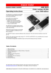
maxon motor
maxon motor control
Operating Instructions
4-Q-DC Servo Control LSC 30/2
Order number 250521
June 2010 Edition
The LSC 30/2 (Linear Servo Controller) is a linear
4-Q-Servoamplifier used to control DC motors up to
approx. 50 W that are powered by permanent magnets.
It allows the following operating modes:
• IxR compensation
• Voltage regulator
• Digital encoder control
• DC tacho control
• Current control
The required operating mode is easily selected using a DIP
switch.
There are also several ways of choosing the set value input:
• ± 10 V to connect to layout systems, such as a positioning
controller
• auxiliary voltages ± 3.9 V are already provided by the LSC
for use with external potentiometer
• well suited for fixed speed adjustment using internal
potentiometer
Its wide input voltage, ranging from 12 – 30 VDC, makes the LSC very flexible for use with different voltage
sources. The modular-style aluminum housing offers several fastening options, notably plugging into a 19”
rack (3HE). Separable screw terminal strips and a robust controller design make the amplifier ideal for
immediate use.
Table of contents
1
2
3
4
5
6
7
8
9
10
11
Safety Instructions ...........................................................................................................................................2
Technical Data .................................................................................................................................................3
Minimum External Wiring .................................................................................................................................4
Start-up Procedure...........................................................................................................................................6
Inputs and Outputs...........................................................................................................................................8
Operating Status Display ...............................................................................................................................12
Error Handling................................................................................................................................................12
EMC-compliant installation ............................................................................................................................13
Block Diagram................................................................................................................................................13
Dimension Drawing........................................................................................................................................14
Spare Parts List .............................................................................................................................................14
The latest edition of these operating instructions may be downloaded from the Internet as a PDF-file under
www.maxonmotor.com category Service & Downloads, Order number 250521 or
in the e-shop http://shop.maxonmotor.com.
maxon motor
4-Q-DC Servo Control LSC 30/2
Operating Instructions
1 Safety Instructions
Skilled personnel
Only skilled, experienced personnel should install and start the equipment
Statutory regulations
The user must ensure that the amplifier and the components belonging to it
are assembled and connected according to local statutory regulations.
Load disconnected
For initial operation, the motor should be free running, i.e. with the load
disconnected.
Additional safety equipment
Any electronic equipment is, in principle, not fail-safe. Machines and
apparatus must therefore be fitted with independent monitoring and safety
equipment. If the equipment breaks down, if it is operated incorrectly, if the
control unit breaks down or if the cables break etc., it must be ensured that
the drive or the complete apparatus is kept in a safe operating mode.
Repairs
Repairs may only be carried out by authorized personnel or the
manufacturer. It is dangerous for the user to open the unit or carry out any
repairs.
Danger
Ensure that no apparatus is connected to the electrical supply during
installation of the LSC 30/2! After switching on, do not touch any live parts!
Max. supply voltage
Make sure that the supply voltage is between 12 and 30 VDC. Voltages
higher than 32 VDC or of the wrong polarity will destroy the unit.
Electrostatic sensitive device (ESD)
2 maxon motor control
June 2010 Edition / Subject to change
maxon motor
Operating Instructions
4-Q-DC Servo Control LSC 30/2
2 Technical Data
2.1
Electrical data
Supply voltage VCC.....................................................................................................12 – 30 VDC
Max. output voltage.................................................................................................................25 V
Max. output current Imax.............................................................................................................2 A
Max. power output .................................................................................................................50 W
It is advisable to consider mounting on a heat sinking surface if ambient temperature is high and
there is a high power loss in the LSC !
2.2
Inputs
Set value “+Set / -Set”.......................... configurable ....................... -10 ... +10 V or -3.9 ... +3.9 V
Disable “Dis IN”.................................... Disable ....................................................... min. VCC - 1 V
Enable..................................................... max. Gnd + 1 V
DC tacho “+T / -T” .................................................................................min. 2 VDC, max. 50 VDC
Encoder signals “Ch A / Ch B” .................................................................max. 100 kHz, TTL level
2.3
Outputs
Status reading “Ready” ........................ Open collector .........................max. 30 VDC (IL < 20 mA)
Error .......................................... “Ready” = high impedant
Ready........................................................“Ready” = Gnd
2.4
Voltage output
Auxiliary voltages “+Vaux / -Vaux” ..........................+3.9 VDC, max. 2 mA / -3.9 VDC, max. 2 mA
Encoder supply voltage “+Venc” ...................................................................+5 VDC, max. 80 mA
2.5
Motor connections
Motor +; Motor -
2.6
Trim potentiometers
nmax
IxR compensation
Offset
Imax
gain
2.7
Protection
Heat monitoring of power stage ....................................................................................... T > 85°C
2.8
LED indicator
green LED..........................................................................................................................READY
red LED............................................................................................................................. ERROR
2.9
Ambient temperature / humidity range
Operation ........................................................................................................................ 0...+45°C
Storage ........................................................................................................................-40...+85°C
No condensation ............................................................................................................. 20...80 %
2.10
Mechanical data
Weight...................................................................................................................... approx. 330 g
Mounting plate ...................................................................................................... for 4 screws M4
Dimensions .............................................................................see dimension drawing, chapter 10
2.11
Terminals
separable PCB terminals ................................................................................................... 16-pole
Pitch ..................................................................... 3.5 mm
suitable for wire cross-section....................... AWG 28-18
0.14 ... 1 mm2 multiple-stranded; 0.14 ... 1.3 mm2 single wire
June 2010 Edition / Subject to change
maxon motor control 3
maxon motor
4-Q-DC Servo Control LSC 30/2
Operating Instructions
3 Minimum External Wiring
7
8
9
Gnd
6
+Venc
5
16
4
10 11 12 13 14 15 16
15
3
T/ChA
9
+T/ChB
8
14
7
Ready
6
13
5
Dis +V
+Set
4
12
Vaux
Set
3
Dis IN
Gnd
+Vaux
2
11
Motor
+Vcc
1
10
+Motor
12...30 VDC
1
Power
supply
SigGnd
Operating mode
2
3.1
Voltage
Regulator
1 2
OFF
ON
OFF
IxR
IxR
1 2
Gnd
+5 V
Ch B
Ch A
1 2
unten
13
14
15
16
ON
Tacho
Tacho
OFF
OFF
ON
Encoder
Encoder
1 2
13
14
ON
OFF
ON
4 maxon motor control
Current
1 2
June 2010 Edition / Subject to change
maxon motor
Operating Instructions
7
8
9
3
4
5
6
7
8
9
7
8
Gnd
6
+Venc
Set
+Set
5
T/ChA
Vaux
4
+T/ChB
Gnd
+Vaux
3
Ready
Motor
+Vcc
2
Dis +V
+Motor
1
1
Dis IN
SigGnd
Set value input
2
Set value -10 ... +10V
OFF
ON
8
9
+3.9V
Motor turns clockwise
0V
50kΩ
Motor turns counterclockwise
OFF
-3.9V
ON
7
Motor turns counterclockwise
P3
Motor turns clockwise
8
Offset
OFF
ON
June 2010 Edition / Subject to change
internal
internal
7
with external
potentiometer
-3.9 ... +3.9 V
6
with internal
potentiometer
P3
5
external
positive set value: motor turns clockwise
negative set value: motor turns counterclockwise
with external
set vallue
-10 ... +10 V
16
15
14
13
12
11
10 11 12 13 14 15 16
10
3.2
4-Q-DC Servo Control LSC 30/2
maxon motor control 5
maxon motor
4-Q-DC Servo Control LSC 30/2
Operating Instructions
4 Start-up Procedure
4.1
Power supply layout
Any available power supply can be used as long as it meets the minimum
requirements set out below.
During set-up and adjustment phases, we recommend separating the motor
mechanically from the machine to prevent damage from uncontrolled motion.
Power supply requirements
Output voltage
VCC min. 12 VDC; VCC max. 30 VDC
Ripple
<5%
Output current
depending on load, continuous max. 2A
The required voltage can be calculated as follows:
Known values:
Ö Operating torque MB [mNm]
Ö Operating speed nB [rpm]
Ö Nominal motor voltage UN [V]
Ö Motor no-load speed at UN, n0 [rpm]
Ö Speed/torque gradient of motor ∆n/∆M [rpm/mNm]
Sought values:
Ö
Supply voltage VCC [V]
Solution:
VCC =
UN
∆n
⋅ (n B +
⋅ M B ) + 5V
n0
∆M
Choose a power supply capable of supplying this calculated voltage under load.
The formula takes into account a 5 V maximum voltage drop at the power
stage.
4.2
Function of potentiometers
Potentiometer
Function
Turning direction
left
P1
nmax
P2
IxR
P3
Offset
P4
Imax
P5
gain
1
6 maxon motor control
right
P1
nmax
maximum speed
at maximum set value
Speed lower
Speed higher
P2
IxR
IxR compensation
weak
compensation
strong
compensation
P3
Offset 1
Adjustment = 0 rpm
at 0 V set value
P4
Imax
Current limit
P5
gain
Speed control gain
Motor turns
CCW
lower
min. approx. 0 A
lower
Motor turns
CW
higher
max. approx. 2 A
higher
P3 can also be used for the set value input (see 5.1.1)
June 2010 Edition / Subject to change
maxon motor
Operating Instructions
4-Q-DC Servo Control LSC 30/2
4.3
Adjusting the potentiometers
4.3.1
Pre-adjustment
With pre-adjustment, the potentiometers are set in a preferred position.
Units in the original packing are already pre-set.
Pre-adjustment of potentiometers
4.3.2
P1
nmax
P1
nmax
50 %
P2
IxR
P2
IxR
0%
P3
Offset
P3
Offset
50 %
P4
Imax
P4
Imax
50 %
P5
gain
P5
gain
10 %
Adjustment
Encoder operation
DC tacho operation
Voltage regulator
IxR compensation
Current regulator
Apply max. set value (10 V or 3.9 V) and turn potentiometer P1 nmax until
required max. speed is reached.
Adjust
potentiometer P4 Imax to required limit value.
2.
Limited current in the 0…2 A range can be adjusted in linear fashion with
the P4 potentiometer.
Important: The limit value Imax should be below the nominal current
(max. permissible continuous current) as per motor data sheet.
3. Slowly increase potentiometer P5 gain until the gain is set sufficiently
high.
Important: If the motor is unsteady, vibrates or makes noises, the
selected amplification is too high.
4. Apply 0 V set value and adjust the motor to speed 0 rpm with
potentiometer P3 Offset.
Important: DIP switch S9 must be set in the “ON Д position for offset
adjustment.
Applicable to IxR compensation only:
5. Slowly increase potentiometer P2 IxR until compensation is set
sufficiently high so that the motor speed does not drop or only drops very
slightly at higher motor load.
Important: If the motor is unsteady, vibrates or makes noises, the
selected compensation is too high.
1.
1.
2.
Adjust potentiometer P4 Imax to required limit value.
Limited current in the 0…2 A range can be adjusted in linear fashion with
the P4 potentiometer.
Important: The limit value Imax should be below the nominal current
(max. permissible continuous current) as per motor data sheet.
Apply 0 V set value and adjust the motor to current 0 A with
potentiometer P3 Offset.
Important: DIP switch S9 must be set in the “ON Д position for offset
adjustment.
Note:
• DIP switch S10 in position:
“ON Д: Set value range -3.9 ... +3.9 V equivalent to approx. -2 ... +2 A
motor current
“OFF Ï”: Set value range -10 ... +10 V equivalent to approx. -2 ... +2 A
motor current
• In current regulator operation, potentiometers P1 nmax, P2 IxR and P5 gain
are not active.
June 2010 Edition / Subject to change
maxon motor control 7
maxon motor
4-Q-DC Servo Control LSC 30/2
Operating Instructions
5 Inputs and Outputs
5.1
Inputs
5.1.1
Set value “Set”
The set value can be applied externally via an analogue voltage or internally
using potentiometer P3.
If the set value is applied externally using the “+Set” and “-Set” connections,
DIP switch S9 must be in the “ONД position.
Two different ranges can be selected to apply an external analogue set value.
The required range is determined by the position of DIP switch S10.
Set value range -10 ... +10 V
Input voltage range
Input wiring
Input impedance
positive set value
negative set value
DIP switch S10
DIP switch S9
-10 ... +10V
differential
200 kΩ (differential)
(+Set) > (-Set)
positive motor voltage or current
(+Set) < (-Set)
negative motor voltage or current
OFFÏ
ONÐ
Use of external potentiometer
Set value range -3.9 ... +3.9 V Input voltage range
Input wiring
Input impedance
positive set value
negative set value
DIP switch S10
DIP switch S9
recommended potentiometer
-3.9 ... +3.9 V
differential
200 kΩ (differential)
(+Set) > (-Set)
positive motor voltage or current
(+Set) < (-Set)
negative motor voltage or current
ONÐ
ONÐ
50 kΩ (linear)
Use of internal potentiometer P3
If the set value is adjusted internally via potentiometer P3, DIP switch S9 must
be in the “OFFÏ” position.
P3 = 50 ... 100 % (right end stop)
P3 = 50 ... 0 % (left end stop)
Input wiring
DIP switch S10
DIP switch S9
8 maxon motor control
positive motor voltage or current
negative motor voltage or current
(+Set) = (-Set)
short-circuited
optional
OFFÏ
June 2010 Edition / Subject to change
maxon motor
Operating Instructions
5.1.2
4-Q-DC Servo Control LSC 30/2
“Disable”
Enabling or disabling the power stage.
Release “Enable”
Block “Disable”
If the “Dis IN” connection is not connected or at Gnd potential,
the power stage is activated (Enable).
minimum input voltage
Gnd
maximum input voltage
+1 VDC referenced to Gnd
maximum input current
2 mA
If the “Dis IN” terminal is connected with “Dis+V” or
the voltage is higher than VCC -1V, the power stage becomes high impedant and
the motor shaft freewheels and slows down (Disable).
minimum input voltage
VCC - 1 VDC
VCC
maximum input voltage
2 mA
maximum input current
Wiring examples:
a) Switch open = “Disable”; switch closed = “Enable”
“+Vcc”
“Dis IN”
“Gnd”
3
4k7
0.25W
4k7
0.25W
4k7
0.25W
4k7
0.25W
10
4
b) Switch open = “Enable”; switch closed = “Disable”
“Dis+V” terminal [11] or “+Vcc” terminal [3]
“Dis IN”
5.1.3
10
DC tacho
+T
-T
positive tacho voltage
negative tacho voltage
minimum input voltage
maximum input voltage
Input impedance
terminal [14]
terminal [13]
2.0 V
50.0 V
approx. 20 kΩ
Speed control range:
The speed range is set using Potentiometer P1 nmax (max. speed at maximum
set value).
For full speed control with ± 10 V or ± 3.9 V, the tacho input voltage range must
be at least ± 2 V.
Example for a DC-tacho with 0.52 V / 1000 rpm:
2.0 V tacho voltage is equivalent to a speed of approx 3850 rpm. If the full set
value range has been used, the lowest adjustable speed with the nmax
potentiometer is 3850 rpm.
Lower speed ranges can be reached through a reduced set value range or by
using a DC tacho with a higher output voltage, such as 5 V / 1000 rpm.
June 2010 Edition / Subject to change
maxon motor control 9
maxon motor
4-Q-DC Servo Control LSC 30/2
5.1.4
Operating Instructions
Encoder
ChA
ChB
Channel A
Channel B
Encoder supply voltage +Venc
max. encoder input frequency
Voltage level
terminal [13]
terminal [14]
+5 VDC, max. 80 mA
DIP switch S8 OFFÏ:
DIP switch S8 ONÐ:
TTL
low
high
100 kHz
6 kHz
max. 0.8 V
min. 2.0 V
The maximum encoder input frequency can be selected with DIP switch S8.
Standard adjustment is max. encoder frequency of 100 kHz.
DIP switch S8 OFFÏ: “high"
Max. input frequency is 100 kHz
Encoder pulses maximum motor
per revolution
speed
6 000 rpm
1000
512
500
256
128
11 719 rpm
12 000 rpm
23 437 rpm
46 874 rpm
DIP switch S8 ONÐ: “low"
Max. input frequency is 6 kHz
Encoder pulses maximum motor
per revolution
speed
128
2 812 rpm
64
5 625 rpm
32
11 250 rpm
16
22 500 rpm
Note:
To achieve good control characteristics, encoders should be operated at a small
number of pulses per revolution with the DIP switch S8 in position ONÐ “low”.
10 maxon motor control
June 2010 Edition / Subject to change
maxon motor
Operating Instructions
4-Q-DC Servo Control LSC 30/2
5.2
Outputs
5.2.1
Auxiliary voltage “+Vaux” and “-Vaux”
Auxiliary voltage for supplying an external potentiometer (50 kΩ).
5.2.2
+Vaux
positive auxiliary voltage
Output voltage
Max. output current
terminal [5]
+3.9 VDC referenced to Sig_Gnd
2 mA
-Vaux
negative auxiliary voltage
Output voltage
Max. output current
terminal [6]
-3.9 VDC referenced to Sig_Gnd
2 mA
Encoder supply “+Venc”
Auxiliary voltage for supplying the encoder
+Venc
5.2.3
Encoder supply voltage
Output voltage
Max. output current
terminal [16]
+5.0 VDC referenced to Gnd
80 mA
Status reading “Ready”
The readiness or error status can be reported to a higher level control through
the “Ready signal”. In normal circumstances, i.e. with no errors, the “Open
Collector” output is switched to Gnd.
In the event of an error (overheating), the output transistor is blocked.
max. 30V
“Ready”
12
Ima x ≤ 20 mA
Gnd
Input voltage range
max. load current
June 2010 Edition / Subject to change
max. 30 VDC
20 mA
maxon motor control 11
maxon motor
4-Q-DC Servo Control LSC 30/2
Operating Instructions
6 Operating Status Display
A red and green LED shows the operating mode.
6.1
No LED
Reason:
• No supply voltage
• Fuse faulty
• Wrong polarity of supply voltage
6.2
Green LED
• Supply voltage applied
• No error status (overheating)
6.3
Red LED
If the power stage temperature exceeds a limit of approx. 85°C,
the power stage is switched off. (Disable - status).
The red LED comes on and the green LED goes out.
If the power stage temperature falls below approx. 60°C, the motor is restarted.
(Enable - status)
The red LED goes out and the green LED comes on.
Reason:
• High ambient temperature
• High power loss in the LSC
• Bad convection
• Heat sinking surface too small
7 Error Handling
Error
Motor does not turn
Speed not controlled
12 maxon motor control
Possible cause of error
Supply voltage VCC< 12 VDC
Disable not activated
Overheating disconnection active
Set value input 0 V
Incorrect operating mode selected
Bad contact
Incorrect wiring
Current limit too low
Encoder mode: encoder signals
Tacho mode: tacho signals
IxR mode: compensation incorrect
Action
Check terminal [3] voltage “VCC”
Check terminal [10] “Dis IN”
Loss output in the LSC too high
Check terminal [7] “-Set” and [8] “+Set”
Check adjustments at DIP switch
Check terminals
Check wiring
Check adjustment Potentiometer P4 Imax
Check “ChA” [13] “ChB” [14] sequence
Check polarity “-T” [13] and “+T” [14]
Check adjustment Potentiometer P2 IxR
June 2010 Edition / Subject to change
maxon motor
Operating Instructions
8
4-Q-DC Servo Control LSC 30/2
EMC-compliant installation
Power supply (+VCC - Power Gnd)
•
No shielding normally required.
•
Star point-shaped wiring if several amplifiers are supplied by the same power supply.
Motor cable
•
No shielding normally required.
Encoder cable
•
Although the LSC 30/2 does not have a line receiver, using an encoder with a line driver is
recommended as this improves interference resistance.
•
Use cable shielding in electromagnetically harsh environment.
•
Connect shielding on both sides (LSC housing).
•
Use separate cable.
Analogue signals (Set, Tacho, Vaux)
•
No shielding normally required.
•
Use cable shielding with analogue signals with small signal level and electromagnetically
harsh environment.
•
Normally connect shielding on both sides (LSC housing). Place shielding on one side if
there are 50/60 Hz interference problems.
Digital signals (Disable, Ready)
•
No shielding necessary.
In practical terms, only the complete equipment, comprising all individual components
(motor, amplifier, power supply unit, EMC filter, cabling etc.) can undergo an EMC test to
ensure interference-free CE-approved operation.
9 Block Diagram
-Vaux
Sig Gnd +Vaux
Dis +V Dis IN Ready
+5V
DIP10
-3.9V/2mA
+3.9V/2mA
+3.9V
+Vcc
+Venc
Supply
-3.9V
+Set value
-Set value
+Vcc 12-30VDC
Control &
Protection
Logic
DIP7
Gnd
+5V/80mA
Gnd
P5 gain
P4 I max
PI
Speed Control
Current
Limit
DIP8
Ch A
DIP6
F/V Converter
Ch B
PI
Current
Control
+Motor
Linear
Power
Stage
-Motor
DIP1
+Tacho
-Tacho
DIP5
DIP9
P1 n max
P3 Offset
P2 IxR
DIP3
Current
Detector
DIP4
Voltage
Detector
DIP2
June 2010 Edition / Subject to change
maxon motor control 13
maxon motor
4-Q-DC Servo Control LSC 30/2
Operating Instructions
10 Dimension Drawing
Dimensions in [mm]
11 Spare Parts List
14 maxon motor control
maxon motor order number
Designation
282310
16 poles pluggable PCB connector
pitch 3.5 mm
June 2010 Edition / Subject to change