1
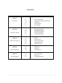
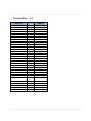
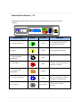
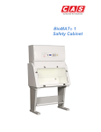
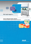
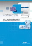
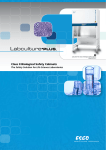
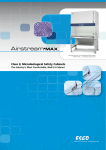
Horizontal Laminar
Flow Cabinet
Contained Air Solutions Ltd | Unit 4 Greengate | Middleton Junction | Manchester M24 1RU |
T +44 (0)161-655-8860 | F +44 (0)161-655-8865
[email protected] | www.containedairsolutions.co.uk
We reserve the right to change specification without notice. © 2009 Contained Air Solutions Ltd
Contents
Section
Description
Section 1
Your Manual
Section 2
Using your Cabinet
Section 3
Cabinet Control Panel
Section 4
Filter Replacement
Section 5
Service & Spares
1.1
1.2
1.3
1.4
1.5
General Description
Quality Assurance/CE compatibility
Installation
Technical Data
Your Manual
2.1
2.2
2.3
2.4
2.5
Switches & Indicators
Start Up Procedure
Shut Down Procedure
Cleaning Procedure
Ultraviolet Radiation
3.1
3.2
3.3
3.4
3.5
Display
Alarm Circuits
Electrical Protection
Fan Speed Control
Engineers Menu
4.1
4.2
4.3
HEPA Filter
Pre-Filter
General Notes
5.1
5.2
5.3
Service Schedule
Spares List
Drawing (attached)
General Description – 1.1
C.A.S. Horizontal Laminar Flow Workstations are designed to provide a localised clean air area,
for manipulations that require a particle free or sterile environment.
The unit carcase is manufactured from mild steel with a white epoxy coating to give a hard
durable finish. The working surface is stainless steel to resist scratches and abrasion and to be
free from discolouration by chemicals. Fluorescent lighting illuminates the working area.
The latest in microprocessor and fan technology is utilised to exceed the performance
requirements of the European Standard BSEN 14644 Class 3, 4 or 5 and EC GMP Grade A
Class F to BS 5295 Class 100 (Federal Standard 209E)
It should be remembered that CAS Horizontal Laminar Flow Workstations direct the air from
the work towards the operator. They must therefore not be used for work involving any
materials that can produce biological or chemical hazards to the worker. For protection
against such hazards Contained Air Solutions Limited produces a range of Microbiological and
Pharmaceutical Safety Cabinets.
This user manual has been prepared to give basic operating and maintenance instructions. It
is only ever intended to supplement existing in-house procedures and not to replace them. If
further advice on the use of this equipment is required, Contained Air Solutions Limited will be
pleased to assist where possible.
Quality Assurance – 1.2
Although fully tested before leaving our factory as part of the ISO 9001:2008 Quality
Assurance Programme, the specified performance will only be maintained if your cabinet is
sited correctly and regularly serviced. CAS can only accept responsibility for correct
functioning of your cabinet if: Ø The cabinet is correctly sited in the laboratory to avoid any adverse conditions within
the room that may affect the level of protection.
Ø It has been installed and commissioned by CAS trained personnel or approved
CAS agents.
Ø Extension, modification, relocation, repairs or other maintenance is carried out by
CAS personnel or persons authorised by CAS or, in the case of electrical work, by
qualified electricians.
Ø In the case of repair or maintenance, replacement parts supplied by CAS must
be used.
Ø The electrical installation surrounding the unit and to which it is connected comply
with the latest IEC regulations.
Ø The unit is used and maintained in compliance with the instructions contained in this
manual.
CE Declaration of Conformity
CAS declares that the equipment supplied conforms to the following CE directives—
Machinery 2006/42/EC
Electro Magnetic Compatibility 2004/108/EC
Low Voltage 2006/95/EC
Installation – 1.3
Horizontal Laminar Flow cabinets are sophisticated items of equipment containing delicate
filters which require expertise in their safe handling and installation into laboratories.
A poorly installed cabinet may compromise the protection provided by the cabinet to work
being handled.
·
Commissioning (On site optional extra)
When any cabinet is installed, it is necessary to carry out a number of commissioning checks in
order to ensure it is fully operational and that the performance on site satisfies the current
standard BS EN 14644 Class 3, 4 or 5. This includes testing the HEPA filters with a suitable
challenge aerosol and a particle count test to assess the cleanliness of the cabinet.
CAS employs a team of fully trained installation and commission engineers to carry out all
work necessary. This ensures that all new HLF cabinets operate to the desired performance.
·
Site Surveys
If you have any queries regarding the siting of your HLF cabinets we will be only too pleased to
arrange a site survey by one of our regionally based technical support staff.
·
Periodic Maintenance & Servicing
To maintain HLF cabinets at their optimum level of performance and to ensure lifetime
operation, regular servicing is necessary. CAS provides a full servicing and maintenance
scheme tailored to suit your individual needs. For more information on this please contact our
service department on 0161-655-8860.
Technical Data – 1.4
Cabinet Size
Dimensions
External Dimensions
Internal Dimensions
Work Tray
1200mm
(w/d/h)
(w/d/h)
(w/d)
1200/750/1302
1100/500/730
1100/500
Weight Typical
Kg
200
Loading Capacity
Work Surface
Kg
50
m/sec
0.45
Pa
Pa
250
350
HEPA Filter Data
HEPA Type
Efficiency
@ 0.3µ
H14 (EN1822)
99.999%
Heat Gains Typical
Recirc
Watts
500
Noise Typical
Noise Level
dB (A)
<60
Light Typical
Interior
Lux
800
Volts
AC
Hz
N/A
kW
A
230
Air Velocity Typical
Air Velocity
Pressure Drop Typical
Clean Filters
Dirty Filters
Electrical Data Typical
Voltage
Frequency
Phase
Power Consumption
Current
Internal Socket
50
Single
0.70
4
230v /13 Amp
Your Manual – 1.5
This user manual has been prepared to provide a basic operating and maintenance
instruction. It is intended to supplement existing in-house procedures and codes of practice,
and not to replace them. If further advice is required on the use or maintenance of this
equipment, the staff of Contained Air Solutions Ltd. will be pleased to assist wherever
possible.
Switches & Indicators – 2.1
The diagram below shows a typical control panel membrane layout for the HLF
cabinet.
0
LAMINAR FLOW
CAS
1
DESCRIPTION
LEGEND
COLOUR
FUNCTION
A – Cabinet Operation
Green
Starts / Stops power supply to
fans and control circuits.
B – Lights
Yellow
Controlling power to lights.
C – Gas Valve (NOT
APPLICABLE)
Black
D – Alarm Mute
Red
E – Fumigate (NOT
APPLICABLE)
Orange
F – UV Lights (Optional)
Blue
0
G – Key Switch
To mute audible alarm. Fault
indication on display will remain
until fault is rectified.
1
Grey Border
To activate power to UV Lights.
Will only operate when cabinet
and lights are switched OFF.
Key switch for supervisor control,
used to prevent cabinet
operation.
Start Up Procedure – 2.2
The following notes are for guidance where local laboratory instructions do not exist or are
inappropriate. They should complement, not replace, existing codes of practice issued by
your Laboratory Safety Officers.
Ø Ensure power supply to the cabinet is switched on, as evidenced by the main display
being illuminated. The key switch on the front of the cabinet must be turned to
position ‘1’ = (ON).
Ø Press the green switch ‘A’ on the control panel – this will energise the integral fan. The
main display will show `AIRFLOW STABILISING` for 60 seconds, once the airflow is
settled the display will show `LAMINAR FLOW AIRFLOW SAFE`. On start up the audible
alarm will sound until airflows are safe; this may be muted using the Alarm Mute
switch `D’.
Ø Switch on the interior lighting using switch ‘B’. Lighting can be activated when the
cabinet is OFF; this can be used if loading or un-loading the cabinet with equipment
prior to use.
Shut Down Procedure – 2.3
Ø The work area should be cleared of any apparatus / equipment and cleaned in
accordance with laboratory codes of practice. The cabinet should be left running for a
few minutes to clear any residual aerosols.
Ø Switch off the interior light using switch `B`
Ø Switch off the cabinet using switch `A`.
Cleaning Procedure – 2.4
Regular cleaning is very important to prevent the build-up of dirt and hence potentially
infectious material. Routine swabbing of work surfaces with 70% v/v IMS (ethanol) or IPA
(Isopropyl Alcohol) is recommended.
For cleaning the work surfaces, swabbing with a mild detergent in warm water is very
effective. Phenolic or Cresolic disinfectants should be avoided as they may stain the white
surfaces with a brownish colour. If they are used, any spillage should be quickly rinsed with
clean water and mopped up with an absorbent tissue. Most of the quaternary ammonium
compounds and the Glutaraldehyde based surface disinfectants are suitable.
NOTE: The rear wall of the working area is formed by the HEPA filter. Although protected by a
metal mesh, care must be taken not to damage the filter membrane, and splashing it should
be avoided if possible. If the protective grille has become soiled it may be cleaned by gently
wiping with a damp cloth.
If Hypochlorites are used to clean the stainless
steel of the cabinet they will initially cause rust
spots and over time may lead to further damage.
Warning
Ultraviolet Radiation (Optional) – 2.5
Ultraviolet Radiation (UV) lamps may be fitted as an optional extra; these can be fitted as new in
our factory or retrofitted at a later date on site. If installed the cabinet will have 2 short wavelength
Ultraviolet (UV) tubes emitting 254 nano metres fitted inside the work area of the cabinet.
As a safety feature the UV tubes are interlinked with the cabinet lights to prevent them being used
when the cabinet is in use.
Over time, the effective life of UV tubes is known to reduce; therefore we would recommend UV
tubes are replaced on an annual basis to ensure maximum efficiency.
Applications
Many bacteria are quite resistant to UV Radiation, and may require prolonged exposure for
sterilisation. Dry and/or protein covered organisms may be protected against UV and may be only
slightly affected if at all. However, moist, vegetative cells without too much protein covering are
killed with reasonable effectiveness after 3-4 hours exposure.
Extreme care must be exercised when using UV
radiation. Consult your Laboratory Safety Officer
prior to use.
Warning
UV Radiation can cause burns to unprotected skin
and it is very important not to look directly at the
illuminated tubes with the naked eye.
Display - 3.1
The cabinet display is located in the centre of the control membrane; it incorporates
backlighting to ensure all signs can be clearly seen from the operating position.
Typical display during normal operation shown below:
LAMINAR FLOW
AIRFLOW SAFE
In the event of an alarm condition the display will clearly indicate the fault; this will remain
displayed until the fault is rectified.
Typical display during alarm condition shown below:
LO W A IR FLO W
Should the cabinet produce an alarm condition it may be necessary to arrange for a Service
Engineer to attend site, in such cases please contact our Service Department on 0161-6556183.
Alarm Circuits – 3.2
There is only one standard alarm circuit on the Horizontal Laminar Flow cabinet.
1.
AIRFLOW
Sensed by an accurate pressure sensor mounted on the main printed circuit board
and connected via tubing to the sensing points within the cabinet body, this will sense low
airflow caused by fan failure or filter soiling, and transmit the signal to the display meter on
the front panel and alarm circuit. In the event the alarm is triggered the display will show
`LOW AIRFLOW`, and the audible alarm will sound, this can be muted using the alarm mute
button.
** The alarm circuit is activated each time the cabinet is switched on.
It is important to ensure that the pressure tubing is not damaged or split where it is connected
to the pressure sensor. The pressure sensor, in the event of inadequate airflow in either part
of the system, will cause the alarm circuit to be activated with a flashing red indicator on the
alarm mute button, an intermittent audible alarm tone, and the alarm system will clearly show
on the display. The audible alarm tone can be silenced by depressing the ‘alarm mute’ button
on the control panel after which the red light will remain continuously lit until the correct
airflow is reinstated or the cabinet is switched off.
Electrical Protection – 3.3
Ensure the Safety Cabinet is isolated from the
mains supply prior to opening access panels.
Warning
Fuses
There is one fuse mounted on the printed circuit board to protect the electrical circuits of the
cabinet. The cabinet controls are housed behind the front control panel which is secured with
two screws located across the bottom edge. Once removed the control panel will hinge
upwards to facilitate access to the main printed circuit board.
For full details on fuse rating and the circuits it protects please see the wiring diagram
attached to this manual.
Fan Speed Control – 3.4
The fan can be adjusted via the engineer’s menu please see section 3.5 for more information.
To maintain optimum performance during routine planned maintenance it may be necessary
to increase cabinet fan speed to overcome filter soiling. This can be adjusted via the front
control panel membrane using the Engineer’s Menu.
It is important any changes to fan speed must be
made by a CAS service engineer or alternative
competent service provider, failure to do this may
result in the warranty being invalid.
Warning
Engineer’s Menu – 3.5
It is important that any changes within the
Engineer’s Menu be conducted by a CAS service
engineer or alternative competent service provider;
failure to do so may result in the warranty being
invalid.
Warning
The buttons located on the front control membrane have a second function once access to
the Engineer’s Menu has been gained.
** In order to gain access to the Engineer’s Menu the cabinet must be switched OFF **
STANDARD SWITCH PANEL ARRANGEMENT
SOFT BUTTON ARRANGEMENT
TO ENTER `ENGINEERS MENU` BUTTON 1 SHOULD HELD DOWN FOR >5 SECONDS
TO EXIT `ENGINEERS MENU` BUTTON 1 SHOULD HELD DOWN FOR >5 SECONDS
USE BUTTON 2 TO START / STOP THE FANS
Engineer’s Menu Sequence
LO W A LA R M
4 0 Pa
Y ES
NO
FA N S PE ED
40 %
Y ES
NO
U .V . LIG H T IN G
0 6 0 M IN UT E S
Y ES
NO
HOURS RUN
08 HRS
Y ES
NO
C LE AR H O UR S R UN
Y ES
INIT IAL IS E V AL UE
Y ES
INIT IA LIS E (0 )
HEPA Filter – 4.1
The single HEPA filter is mounted immediately behind the working area. Access is
gained by removing the rear access panel, held in place by screws. The filter and air
equalisation plate is retained by screwed clamps. When these are released the plate
and used filter can be pulled free and removed. The frame surfaces should be cleaned
carefully and any grit particles removed. The new filter gasket should be lightly
greased with Dow Corning silicone grease or similar prior to being placed in position.
The clamps should be replaced and tightened so as to compress the gaskets by about
one third. Care must be exercised not to over-tighten and over compress the gasket.
The access panel must then be replaced after ensuring its gasket is in good condition.
IMPORTANT
Cabinet must be decontaminated prior to changing any HEPA filters, see section 2.6
Only replace or examine filters if authorised to do so by the Safety Officer or the person in
charge of the laboratory. To remove any filters wear disposable gloves, an apron, overalls
and appropriate face covering, especially eye protection.
Ensure the cabinet is isolated from the mains
supply prior to opening access panels.
Warning
Pre-Filter – 4.2
The pre-filter pads are located at the top of the cabinet and simply drop into place on
their retaining frame. The pre-filter pads should be examined frequently (Once each
month) for heavy soiling and replaced on a regular basis to prolong the life of the main
HEPA filter.
IMPORTANT
Only replace or examine filters if authorised to do so by the Safety Officer or the person
in charge of the laboratory. To remove any filters wear disposable gloves, an apron,
overalls and appropriate face covering, especially eye protection.
Ensure the cabinet is isolated from the mains
supply prior to opening access panels.
Warning
General Notes – 4.3
Ø The amount of equipment stored in the cabinet should be kept to a minimum to
reduce the disruption to the airflow patterns within the cabinet.
Ø A Bunsen burner should not be used inside the cabinet.
Ø The failsafe solenoid operated gas valve (If fitted) will only allow gas to flow when the
cabinet is switched on and there is a satisfactory airflow. Any interruption in the
power supply or failure of air supply necessitates manual resetting of the valve by
depressing the switch on the control panel marked ‘gas valve’.
Ø As a safety feature the UV tubes (If fitted) are interlinked with the cabinet lights to
prevent them being used when the cabinet is in use.
We recommend cabinet users to consult their own laboratory safety information. Other
publications available include:
Science Reviews Ltd, Occupational Hygiene Monograph No.9
British Standard BS EN 12469:2000 & 5726-2000 Part 5
Australian Standard AS2567
American National Sanitation Foundation Standard No. 49
We would also recommend the latest guidelines issued by the UK Advisory Committee on
Dangerous Pathogens (ACDP). These documents contain much useful information on the
performance, installation, testing, use and limitations of laminar flow cabinets.
Service Schedule 5.1
SERVICE SCHEDULE 5.1
Horizontal Laminar Flow Cabinets
Schedule of work included in service agreement
1
Filter Integrity Test (D.O.P) on all main filter(s) and seals
2
Airflow Profiling ensuring compliance to latest British & European Standards
3
Check and adjust alarm parameters & control functions as required
4
Air cleanliness test within work zone (particle counts)
5
Check and adjust electrical and electronic controls as related to the airflow system
6
Mechanically inspect cabinet components
7
Change main filters as necessary (Supply and fitting subject to additional charge)
8
Prepare computer generated Service Report
Above work to be carried out twice each service year
Spares List 5.2
Shown below are ordering codes for the most common parts used on the Horizontal Laminar
Flow cabinets. In addition to these items we stock a vast range of Spares, consumables and
optional extras. If you cannot see what you require please give us a call on the telephone
number shown below.
** Please note cabinet serial number must be quoted when ordering **
ORDERING CODES
Item
HLF 1200mm
HEPA Filter
112575566
Pre-Filter
30/30G4
49729347
Fan
FAN 030
Main PCB
ELC 346
Control Membrane
LAB 114
Light Tube
ELC 077
UV Light Tube (Optional)
ELC 061
Key Switch
ELC 199