1
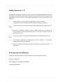
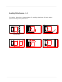
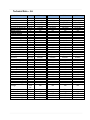
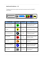
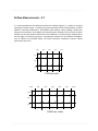
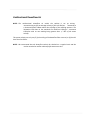
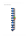
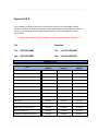
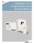
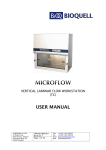
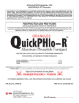
BioMAT® 2
Safety Cabinet
Contained Air Solutions Ltd | Unit 4 Greengate | Middleton Junction | Manchester M24 1RU |
T +44 (0)161-655-8860 | F +44 (0)161-655-8865
[email protected] | www.containedairsolutions.co.uk
We reserve the right to change specification without notice. © 2009 Contained Air Solutions Ltd
Contents
Section
Description
Section 1
Your Manual
Section 2
Using your Cabinet
Section 3
Cabinet Control Panel
Section 4
Filter Replacement
Section 5
Service & Spares
1.1
1.2
1.3
1.4
1.5
1.6
1.7
General Description
Quality Assurance/CE compatibility
Cabinet Siting
Installation
Avoiding Disturbances
Technical Data
Your Manual
2.1
2.2
2.3
2.4
2.5
2.6
2.7
2.8
Switches & Indicators
Start Up Procedure
Shut Down Procedure
Cleaning Procedure
Fumigation & Formalin Quantities
Fumigation Procedure
Airflow Measurements
Ultraviolet Radiation
3.1
3.2
3.3
3.4
3.5
Display
Alarm Circuits
Electrical Protection
Fan Speed Control
Engineers Menu
4.1
4.2
4.3
4.4
Downflow HEPA Filter
Re-circ HEPA Filter
Exhaust HEPA Filter
General Notes
5.1
5.2
5.3
5.4
Service Schedule
Spares List
Drawings (attached)
Wiring Diagrams (attached)
General Description – 1.1
Your BioMAT 2 Microbiological Safety Cabinet has been designed to provide optimum
performance for both operator and product protection. Using the latest in microprocessor and
fan technology, it is designed to exceed the performance requirements of the European
Microbiological Safety Cabinet Standard EN12469:2000. The safety cabinet carcass and all
seals are maintained under negative pressure ensuring air cannot leak out during normal
operation.
Class 2 Safety Cabinets offer both operator and product protection; they ensure any aerosols
generated within the cabinet are filtered via high efficiency filtration (HEPA) prior to being
dispersed back into the laboratory or to atmosphere. Operator protection is provided by an air
curtain across the working aperture of the front screen. Protection of the products from
external contamination is provided by a unidirectional downflow of sterile air into the working
area.
The Class 2 Microbiological Safety Cabinet can be supplied as standard in either of the
following two modes:
Ø Re-circulating Type – Exhaust air from the safety cabinet is passed through two
high efficiency filters (HEPA) before being released back into the laboratory. The
exhaust air is made up of approximately 40% of the total air volume handled by
the safety cabinet. Approximately 60% of the air is re-circulated within the safety
cabinet and passes through a high efficiency (HEPA) filter to ensure sterility
within the work area.
Ø Exhaust Type – Exhaust air from the safety cabinet is passed through a high
efficiency filter (HEPA) before being extracted to atmosphere through a fan
assisted extract system. The exhaust air is made up of approximately 40% of the
total air volume handled by the safety cabinet. Approximately 60% of the air is
re-circulated within the safety cabinet and passes through a high efficiency
(HEPA) filter to ensure sterility within the work area.
Quality Assurance – 1.2
Although fully tested before leaving our factory as part of the ISO 9001:2008 Quality Assurance
Programme, the specified performance will only be maintained if your cabinet is sited correctly
and regularly serviced. CAS can only accept responsibility for correct functioning of your
cabinet if: Ø
Safety Cabinet is correctly sited in the laboratory to avoid any adverse
conditions within the room that may affect the level of operator protection.
Ø
It has been installed and commissioned by CAS trained personnel or approved CAS
agents.
Ø Extension, modification, relocation, repairs or other maintenance is carried out by
CAS personnel or persons authorised by CAS or, in the case of electrical work, by
qualified electricians.
Ø
In the case of repair or maintenance, replacement parts supplied by CAS must be
used.
Ø
The electrical installation surrounding the unit and to which it is connected
comply with the latest IEC regulations.
Ø The unit is used and maintained in compliance with the instructions contained
this manual.
CE Declaration of Conformity
CAS declares that the equipment supplied conforms to the following CE directives—
Machinery 2006/42/EC
Electro Magnetic Compatibility 2004/108/EC
Low Voltage 2006/95/EC
in
Cabinet Siting – 1.3
The siting of your Safety Cabinet is extremely important. Air currents and the movement of
people in the laboratory can adversely affect the performance.
Safety Cabinets should be sited away from;
Ø
Doors and windows which open
Ø
Draughts caused by ventilation and air conditioning units
Ø
Pedestrian traffic routes
Ø
Other safety cabinets or fume cupboards
Ø
Adjacent fridge & Incubator doors
These points are of particular relevance to class 2 safety cabinets. The diagram shown below
indicates some suggested locations for the correct siting of safety cabinets and highlights some
situations which should be avoided.
3
4
SUPPLY GRILLE
1
2
HORIZONTAL
LAMINAR FLOW
Position 1
-
An acceptable site not affected by disruptive air currents
Position 2
-
Well sited
Position 3
-Poorly sited if windows open – If not it should be a safe distance
from the cabinet opposite.
Position 4
-Poorly sited – can be affected by air currents from the opening door,
through traffic and the horizontal laminar flow workstation
sited directly opposite.
Installation – 1.4
Safety Cabinets are sophisticated items of equipment containing delicate filters which require
expertise in their safe handling and installation into laboratories.
For exhaust type safety cabinets the exhaust ductwork route should ideally be surveyed and
ductwork installation be carried out by qualified engineers as it forms an integral part of the
system relating to the overall performance of the cabinet and is required to conform to various
safety standards.
A poorly installed cabinet may compromise the protection provided by the cabinet to both
personnel and work being handled and may present a hazard to other occupants of the
building and the public.
·
Make-up Air
It is important that any make-up air compensating for the air exhausted from the safety
cabinet does not cause draughts to the discomfort of the laboratory staff or detriment of the
cabinet performance.
Air supply diffusers should be positioned more than 1500mm away from the front of the safety
cabinet and have a maximum velocity of no more than 0.30m/sec.
·
Commissioning
When any safety cabinet is installed, it is necessary to carry out a number of commissioning
checks in order to ensure it is fully operational and that the performance on site satisfies the
current standard BS EN 12469:2000. This includes measuring the airflows, testing the HEPA
filters with a suitable challenge aerosol and a KI Discus Test (operator protection test) to assess
the containment of the cabinet.
CAS employs a team of fully trained installation and commission engineers to carry out all work
necessary. This ensures that all new safety cabinets operate to the desired performance.
·
Site Surveys
If you have any queries regarding the siting of your safety cabinets we will be only too pleased
to arrange a site survey by one of our regionally based technical support staff.
·
Periodic Maintenance & Servicing
To maintain safety cabinets at their optimum level of performance and to ensure lifetime
operation, regular servicing is necessary. CAS provides a full servicing and maintenance scheme
tailored to suit your individual needs. For more information on this please contact our service
department on 0161-655-8860.
Avoiding Disturbances – 1.5
300
The sketches below show recommendations for avoiding disturbances for both cabinet
operator and safety cabinet performance.
1500
1000
Keep pedestrians away from the front
of your safety cabinet
Keep clear of adjacent wall
Position well away from the door openings
Bench
300
C
2000
1500
Position clear of bench opposite
Keep clear of structural columns
Keep well away from opposite wall
Technical Data – 1.6
Cabinet Size
900mm
1200mm
1500mm
1800mm
(w/d/h)
(w/d/h)
(w/d)
(w/h)
900/640/1400
760/550/700
720/400
710/200
1200/640/1400
1060/550/700
1020/400
1010/200
1500/640/1520
1360/550/700
1320/400
1310/200
1800/640/1520
1660/550/700
1620/400
1610/200
Weight Typical
Kg
180
230
280
330
Loading Capacity
Work Surface
Kg
50
50
50
50
m³/sec
m³/sec
0.09
0.130
0.130
0.190
0.160
0.240
0.190
0.290
Pa
Pa
400
550
400
550
400
550
400
550
HEPA Filter Data
HEPA Type
Efficiency
@ 0.3µ
H14 (EN1822)
99.999%
H14 (EN1822)
99.999%
H14 (EN1822)
99.999%
H14 (EN1822)
99.999%
Heat Gains Typical
Exhaust
Re-circ
Watts
Watts
190
100
190
100
270
135
350
175
Noise Typical
Noise Level
dB (A)
<58
<58
<58
<58
Light Typical
White interior
St/St Interior
Lux
Lux
1000
800
1000
800
1000
800
1000
800
Duct Connection (Exh)
Mm
160
160
200
200
Volts
AC
Hz
N/A
kW
A
230
230
230
230
50
Single
0.19
3
230v /13 Amp
50
Single
0.19
3
230v /13 Amp
50
Single
0.27
5
230v /13 Amp
50
Single
0.35
7
230v /13 Amp
Dimensions
External Dimensions
Internal Dimensions
Work Tray
Opening to Work Area
Air Volumes Typical
Exhaust Air Volume
Re-circ Air Volume
Pressure Drop Typical
Exhaust Clean Filters
Exhaust Dirty Filters
Electrical Data Typical
Voltage
Frequency
Phase
Power Consumption
Current
Internal Socket(s)
Your Manual – 1.7
This user manual has been prepared to provide a basic operating and maintenance instruction.
It is intended to supplement existing in-house procedures and codes of practice, and not to
replace them. If further advice is required on the use or maintenance of this equipment, the
staff of Contained Air Solutions Ltd. will be pleased to assist wherever possible.
Switches & Indicators – 2.1
The diagram below shows a typical control panel membrane layout for the BioMAT 2
safety cabinet.
BioMAT2
0
AIRFLOW SAFE
1
BioMAT 2
CLASS2 MICRO
BIO
LOG
ICA
LSA
FETYC
ABINET
CO
MPLIESWITHBS EN12469:2000
DESCRIPTION
LEGEND
COLOUR
FUNCTION
A – Cabinet Operation
Green
Starts / Stops power supply to
fans and control circuits.
B – Lights
Yellow
Controlling power to lights.
C – Gas Valve (Optional)
Black
D – Alarm Mute
Red
E – Fumigate
Orange
F – UV Lights (Optional)
Blue
0
G – Key Switch
1
Grey Border
To activate solenoid Gas Valve.
Will only function when cabinet is
in safe working condition.
To mute audible alarm. Fault
indication on display will remain
until fault is rectified.
To activate fumigation cycle. Will
only operate when cabinet is
switched OFF.
To activate power to UV Lights.
Will only operate when cabinet
and lights are switched OFF.
Key switch for supervisor control,
used to prevent cabinet operation
during fumigation.
Start Up Procedure – 2.2
The following notes are for guidance where local laboratory instructions do not exist or are
inappropriate. They should complement, not replace, existing codes of practice issued by your
Laboratory Safety Officers.
Ø
Ensure power supply to the cabinet is switched on, as evidenced by the main display
being illuminated. The key switch on the front of the cabinet must be turned to position ‘1’ =
(ON).
Ø
Press the green switch ‘A’ on the control panel – this will energise the exhaust fan
followed by the downflow fans. The main display will show `AIRFLOW STABILISING` for 60
seconds, once airflows are settled the display will show `AIRFLOW SAFE`. On start up the
audible alarm will sound until airflows are safe; this may be muted using the Alarm Mute
switch `D’.
NOTE: Should the airflows change significantly and fall out of the specifications laid
down in EN12469:2000 cabinet alarms will be automatically activated.
Ø
Switch on the interior lighting using switch ‘B’. Lighting can be activated when the
cabinet is OFF; this can be used if loading or un-loading the cabinet with equipment prior to
use.
Shut Down Procedure – 2.3
Ø
The work area should be cleared of any apparatus / equipment and cleaned in
accordance with laboratory codes of practice. The cabinet should be left running for a few
minutes to clear any residual aerosols.
Ø
Switch off the interior light using switch `B`
Ø
Switch off the cabinet using switch `A`.
Ø
Place the closure panel / Night door over the working aperture once complete.
Cleaning Procedure – 2.4
Regular cleaning is very important to prevent the build-up of dirt and hence potentially
infectious material. Routine swabbing of work surfaces with 70% v/v IMS (ethanol) or IPA
(Isopropyl Alcohol) is recommended.
For cleaning the work surfaces, swabbing with a mild detergent in warm water is very
effective. Phenolic or Cresolic disinfectants should be avoided as they may stain the white
surfaces with a brownish colour. If they are used, any spillage should be quickly rinsed with
clean water and mopped up with an absorbent tissue. Most of the quaternary ammonium
compounds and the Glutaraldehyde based surface disinfectants are suitable.
To facilitate cleaning of the work zone and the interior, the whole front screen / visor may be
opened and lowered from the top, supported by the hinges at the lower edge. It is good
practice to clean the inside of the viewing screen to ensure adequate visibility of the working
zone. Always consult the Laboratory Safety Officer before carrying out this procedure.
If Hypochlorites are used to clean the stainless
steel interior of the safety cabinet they will
initially cause rust spots and over time may lead
to further damage.
Warning
Fumigation & Formalin Quantities – 2.5
When handling hazardous materials the air space inside the cabinet should be decontaminated
regularly and always before servicing and following any spillages. Fumigation by formaldehyde
gas is the recommended decontamination procedure for biological hazards although there are
alternative methods available including VHP decontamination and Ozone decontamination.
To facilitate the fumigation a sequence has been incorporated in the cabinet controls, this is
detailed under fumigation procedure.
A convenient way of generating sufficient formaldehyde is to boil off Formalin (40%
formaldehyde BP or equivalent) in a suitable vessel such as a formalin vaporiser. These are
available from CAS.
Always consult your Laboratory Safety Officer
prior to fumigation of a safety cabinet.
** If in doubt ask **
Formalin Quantities
The recommended quantity stated in BS EN12469:2000 on Page 40 Annex J, Part 2 is 60ml
formaldehyde solution mixed with 60ml distilled water per cubic meter of cabinet volume.
However this quantity is now considered in excess of that required to achieve a satisfactory kill.
We have therefore produced the following table based on quantities employed by users of
large numbers of Safety Cabinets.
If you still consider that the quantities recommended in the British Standard are to be used,
you may find on completion of the sterilisation cycle that high quantities of fluids containing
formaldehyde are present in the cabinet.
Cabinet Size
900mm
1200mm
1500mm
1800mm
Formalin
Distilled Water
15ml @40%
15ml
20ml @ 40%
20ml
25ml @ 40%
25ml
30ml @ 40%
25ml
Fumigation Procedure – 2.6
Ø
Switch off the cabinet fans by pressing the green button ‘A’ on the control panel.
Ø
For re-circulating type safety cabinets the fumigation extract kit (optional) should be
fitted to the cabinet discharge and ensure that the manual damper is fully closed. For cabinets
connected to a duct system proceed as follows:
§
Fill the formalin vaporiser with the correct amount of Formalin (see section 2.5 for
quantities) and screw on the aluminium cap – finger tight, having checked the gasket in the cap
is undamaged. If the vaporiser is free standing, place on the cabinet work tray, plug into
cabinet internal socket and switch on. Now fit the closure panel / night door, if using a
lightweight closure panel additional sealing tape will be required around the outside face to
ensure no leakage during fumigation. It is advisable to use a non permeable type tape that will
not leave a residue once removed.
§
Now press the fumigation button `E’ and the display will show `FUMIGATION IN
PROGRESS’. A countdown timer will be shown directly below in minutes e.g. `285 MINS`.
During the first hour of the fumigation cycle the internal fans (downflow fans) will cycle for 5
seconds at 20 minute intervals, this ensures formaldehyde is well dispersed within the cabinet.
Ensure all laboratory personnel are aware that
the fumigation is taking place; appropriate
warning notices should be put on all doors
entering the laboratory and on the cabinet being
fumigated.
Warning
Ø
The cabinet should be left for a minimum of 6 hours, preferably overnight.
Note: Once the ‘fumigate’ button has been activated DO NOT SWITCH CABINET ON
until the cycle has been completed.
Ø On completion the cabinet will display `FUMIGATION COMPLETE` and `READY TO
VENT`. When ready, press the fumigation button to exit the cycle and then press the
green button `A` to purge the cabinet of formaldehyde gas.
For re-circulating type safety cabinets press the ‘fumigate’ button to complete cycle and
open the manual shut-off damper on the fumigation adaptor kit (Optional) having first
fitted the extract tubing and placed the discharge point in a location approved by the
Laboratory Safety Officer.
** When fumigating a re-circulating type safety cabinet where venting is unobtainable,
a mobile carbon filter unit may be required. **
Ø Switch on the cabinet and then remove the sealing tape. To avoid formaldehyde being
drawn out of the cabinet remove the rubber bung when using a 100% sealing closure
panel.
Ø Within the first few minutes of purging, the majority of the formaldehyde gas within
the safety cabinet will be removed. However due to the fact that formaldehyde
adheres to the surfaces of the cabinet and within the media of HEPA
filters,
we
recommend that the cabinet be run continuously for at least 6 hours before the
cabinet is serviced or work re-commences.
Ø
Remove the (optional) fumigation kit from the cabinet discharge before
commencing to use the cabinet.
** Any poly-formaldehyde residue in the vaporiser may be removed by heating with water
containing a little mild detergent at neutral pH.
General Note
Other methods of generating formaldehyde and other methods of cabinet decontamination
can be employed; prior to using alternative methods your Laboratory Safety Officer should be
consulted. Contained Air Solutions will be pleased to advise if they are able, but a detailed
knowledge of every technique cannot be guaranteed.
If your cabinet is fitted with ports to allow fumigation using Vaporised Hydrogen
Peroxide (VHP) please refer to the VHP equipment manufacturer’s manual for the
correct application of this technique.
Airflow Measurements – 2.7
It is recommended that the downward airflow be checked regularly, i.e. weekly or monthly
according to cabinet usage. A rotating vane type anemometer with a head diameter of about
100mm is considered satisfactory. On 1200mm wide cabinets, take 8 readings, namely four
along a line one quarter of the depth of the working space forward of the rear wall, and four
along a line the same distance behind the front window on a horizontal plane 100mm above
the top edge of the working aperture. Anemometer positions for the 1200mm & 1800mm
sizes of cabinet are illustrated below. The results should be recorded to monitor cabinet
performance over time.
1/8
1/4
1/4
1/4
1/8
1/4
1/2
1/4
1200mm wide
1/12
1/6
1/6
1/6
1/6
1/4
1/2
1/4
1800mm wide
1/6
1/12
Unidirectional Downflow Air
NOTE: - The unidirectional downflow air within the cabinet is set up during
commissioning to give an average velocity of 0.3 to 0.35m/sec measured at
a horizontal plane 100mm above the top edge of the working aperture. The
limitations laid down in the standard are minimum 0.25m/sec - maximum
0.50m/sec with no one reading being greater than +/- 20% of the mean
velocity.
This preset velocity can only vary if (a) the soiling of the downflow filter occurred, or (b) should
there be a fan failure.
NOTE: - We recommend that the downflow velocity be checked on a regular basis and the
results recorded to monitor cabinet performance over time.
Ultraviolet Radiation (Optional) – 2.8
Ultraviolet Radiation (UV) lamps may be fitted as an optional extra; these can be fitted as new in
our factory or retrofitted at a later date on site. If installed the cabinet will have 2 short wavelength
Ultraviolet (UV) tubes emitting 254 nano metres fitted to the inside work area of the safety cabinet.
As a safety feature the UV tubes are interlinked with the cabinet lights to prevent them being used
when the cabinet is in use.
Over time, the effective life of UV tubes is known to reduce; therefore we would recommend UV
tubes are replaced on an annual basis to ensure maximum efficiency.
Applications
Many bacteria are quite resistant to UV Radiation, and may require prolonged exposure for
sterilisation. Dry and/or protein covered organisms may be protected against UV and may be only
slightly affected if at all. However, moist, vegetative cells without too much protein covering are
killed with reasonable effectiveness after 3-4 hours exposure.
Extreme care must be exercised when using UV
radiation. Consult your Laboratory Safety Officer
prior to use.
Warning
UV Radiation can cause burns to unprotected skin
and it is very important not to look directly at the
illuminated tubes with the naked eye.
Display - 3.1
The cabinet display is located in the centre of the control membrane; it incorporates
backlighting to ensure all signs can be clearly seen from the operating position.
Typical display during normal operation shown below:
AIRFLOW SAFE
BioMAT 2
In the event of an alarm condition the display will clearly indicate the fault; this will remain
displayed until the fault is rectified.
Typical display during alarm condition shown below:
DOWNFLOW FAIL
Should the cabinet produce an alarm condition it may be necessary to arrange for a Service
Engineer to attend site, in such cases please contact our Service Department on 0161-6556183.
Alarm Circuits – 3.2
There are three standard alarm circuits on the BioMAT 2 Re-circulating and Exhaust type Safety
Cabinets.
1.
INFLOW
Sensed by an accurate pressure sensor mounted on the main printed circuit board and
connected via tubing to the sensing points within the cabinet body, this will sense low airflow
caused by fan failure or filter soiling, and transmit the signal to the display meter on the front
panel and alarm circuit. In the event the alarm is triggered the display will show `LOW
AIRFLOW`, and the audible alarm will sound, this can be muted using the alarm mute button.
1.
DOWNFLOW
Sensed by an accurate pressure sensor mounted on the main printed circuit board and
connected via tubing to the sensing points within the cabinet body, this will sense low airflow
caused by fan failure or filter soiling, and transmit the signal to the display
meter on the
front panel and alarm circuit. In the event the alarm is triggered the display will show
`DOWNFLOW FAIL` and the audible alarm will sound, this can be muted using the alarm mute
button.
2.
FRONT SCREEN
Front screen position is monitored by a micro-switch fitted to the front screen
assembly. When opened the display will show `VISOR OPEN’ and an audible alarm will sound.
This can be muted using the alarm mute button.
** The alarm circuit is activated each time the cabinet is switched on.
It is important to ensure that the pressure tubing is not damaged or split where it is connected
to the pressure sensor. The pressure sensor, in the event of inadequate airflow in either part
of the system, will cause the alarm circuit to be activated with a flashing red indicator on the
alarm mute button, an intermittent audible alarm tone, and the alarm system will clearly show
on the display. The audible alarm tone can be silenced by depressing the ‘alarm mute’ button
on the control panel after which the red light will remain continuously lit until the correct
airflow is reinstated or the cabinet is switched off.
Electrical Protection – 3.3
Ensure the Safety Cabinet is isolated from the
mains supply prior to opening access panels.
Warning
Fuses
There are 11 fuses mounted on the printed circuit board to protect the electrical circuits of the
cabinet. The cabinet controls are housed behind the front control panel which is secured with
two screws located across the bottom edge. Once removed the control panel will hinge
upwards to facilitate access to the main printed circuit board.
For full details on fuse ratings and the circuits they protect please see the wiring diagram
attached to this manual.
Fan Speed Control – 3.4
Both the inflow and downflow fans can be adjusted via the engineer’s menu please see section
3.5 for more information.
To maintain optimum performance during routine planned maintenance it may be necessary
to increase cabinet fan speeds to overcome filter soiling. This can be adjusted via the front
control panel membrane using the Engineer’s Menu.
It is important any changes to fan speeds must be
made by a CAS service engineer or alternative
competent service provider, failure to do this may
result in the warranty being invalid.
Warning
Engineer’s Menu – 3.5
It is important any changes within the Engineer’s
Menu be conducted by a CAS service engineer or
alternative competent service provider; failure to
do so may result in the warranty being invalid.
Warning
The buttons located on the front control membrane have a second function once access to the
Engineer’s Menu has been gained.
** In order to gain access to the Engineer’s Menu the cabinet must be switched OFF **
STANDARD SWITCH PANEL ARRANGEMENT
SOFT BUTTON ARRANGEMENT
TO ENTER `ENGINEERS MENU` BUTTON 1 SHOULD HELD DOWN FOR >5 SECONDS
TO EXIT `ENGINEERS MENU` BUTTON 1 SHOULD HELD DOWN FOR >5 SECONDS
USE BUTTON 2 TO START / STOP THE FANS
Engineer’s Menu Sequence
LOW ALARM
40 Pa
YES
NO
HIGH ALARM
80 Pa
YES
NO
DOWNFLOW ALARM
YES
120 Pa
NO
INFLOW FAN
65 %
YES
NO
DOWNFLOW FAN
40 %
YES
NO
U.V. LIG HTING
060 MINUTES
YES
NO
TIM E ADJUST
14:54
YES
NO
EXHAUST SENSOR
YES
20 Pa
NO
SERVICE TIMER
YES
RESET
NO
INITIALISE VALUE
INITIALIS E (0)
YES
Downflow HEPA Filter – 4.1
The downflow filter is a single HEPA filter mounted immediately above the working area.
Access is gained by opening the control panel door.
IMPORTANT
Cabinet must be decontaminated prior to changing any HEPA filters, see section 2.6
Only replace or examine filters if authorised to do so by the Safety Officer or the person in
charge of the laboratory. To remove any filters wear disposable gloves, an apron, overalls
and appropriate face covering, especially eye protection.
Ensure the Safety Cabinet is isolated from the
mains supply prior to opening access panels.
Warning
The front control panel is hinged at the top and retained by fixing screws in the lower edge,
when opened it can be supported by two stays. Behind the front control panel is the main
access panel held in place by several screws. Care should be taken to ensure the panel is
supported prior to releasing the last screw.
Behind the access panel is the downflow fan module and the downflow HEPA filter. Turning
the jacking screw clockwise at each side a little at a time until free from the filter will raise the
fan module. The downflow filter may then be drawn forward and out of the cabinet body, this
can then be disposed of as recommended by site regulations.
To replace, first ensure that all surfaces have been cleaned and are free from matter.
Carefully remove the new filter from its protective packing.
Inspect both exposed surfaces for signs of damage. Any damage should be reported to the
supplier immediately.
The filter should be slid carefully into the cabinet taking care not to damage the gaskets, if
necessary by supporting the filter from within the work area. The fan module is then carefully
lowered by turning the jacking screws anti-clockwise a little at a time so as to compress the
filter gasket to approximately half its original thickness. The panels may then be replaced, and
the filter and its gasket tested for leaks by challenging with DOP or equivalent aerosol and
scanning the surface with the probe of a forward light scattering photometer.
Re-circ HEPA Filter – 4.2
The double HEPA filter is located on the top of the main body of the cabinet held in place by
two compression fasteners.
IMPORTANT
Cabinet must be decontaminated prior to changing any HEPA filters, see section 2.6
Only replace or examine filters if authorised to do so by the Safety Officer or the person in
charge of the laboratory. To remove any filters wear disposable gloves, an apron, overalls
and appropriate face covering, especially eye protection.
Ensure the Safety Cabinet is isolated from the
mains supply prior to opening access panels.
Warning
To remove filter, release fasteners, lift module until filter can be removed. Slide filter forward
and out and dispose of as recommended by site regulations
To replace, first ensure that all surfaces have been cleaned and are free from matter.
Remove new filter from its protective packing.
Inspect both exposed surfaces for signs of damage. Any damage should be reported to the
supplier immediately.
Slide filter carefully into position. Lock fasteners, ensuring filter is correctly positioned and
gaskets are compressed to about half their original thickness.
The filter and its gaskets should be tested for leaks by challenging with DOP or equivalent
aerosol and scanning the surface with the probe of a forward light scattering photometer.
Exhaust HEPA Filter – 4.3
The single HEPA filter is located on the top of the main body of the cabinet held in place by
either two compression fasteners or jacking screws.
IMPORTANT
Cabinet must be decontaminated prior to changing any HEPA filters, see section 2.6
Only replace or examine filters if authorised to do so by the Safety Officer or the person in
charge of the laboratory. To remove any filters wear disposable gloves, an apron, overalls
and appropriate face covering, especially eye protection.
Ensure the Safety Cabinet is isolated from the
mains supply prior to opening access panels.
Warning
To remove filter, release fasteners or jacking screws, lift module until filter can be removed.
Slide filter forward and out and dispose of as recommended by site regulations
To replace, first ensure that all surfaces have been cleaned and are free from matter.
Remove new filter from its protective packing.
Inspect both exposed surfaces for signs of damage. Any damage should be reported to the
supplier immediately.
Slide filter carefully into position. Lock fasteners or jacking screws, ensuring filter is correctly
positioned and gaskets are compressed to about half their original thickness.
The filter and its gaskets should be tested for leaks by challenging with DOP or equivalent
aerosol and scanning the surface with the probe of a forward light scattering photometer.
General Notes – 4.4
Ø
Do not store equipment inside the Microbiological Safety Cabinet. The amount of
equipment should be kept to a minimum to reduce the disruption to the airflow patterns
within the cabinet.
Ø
A Bunsen burner should not be used inside the cabinet.
Ø
Great care should be taken to prevent litter such as disposable gloves or tissues from
being sucked through the airways at the rear of the work area. These can lodge and reduce
the airflow through the cabinet. It is good practice to clean underneath the work tray
regularly. Always consult the Laboratory Safety Officer before carrying out this procedure.
Ø
The failsafe solenoid operated gas valve (If fitted) will only allow gas to flow when the
cabinet is switched on and there is a satisfactory airflow. Any interruption in the power supply
or failure of air supply necessitates manual resetting of the valve by depressing the switch on
the control panel marked ‘gas valve’.
Ø
As a safety feature the UV (If fitted) tubes are interlinked with the cabinet lights to
prevent them being used when the cabinet is in use.
We recommend cabinet users to consult their own laboratory safety information. Other
publications available include:
Science Reviews Ltd, Occupational Hygiene Monograph No.9
British Standard BS EN 12469:2000 & 5726-2000 Part 5
Australian Standard AS2567
American National Sanitation Foundation Standard No. 49
We would also recommend the latest guidelines issued by the UK Advisory Committee on
Dangerous Pathogens (ACDP). These documents contain much useful information on the
performance, installation, testing, use and limitations of Microbiological Safety Cabinets.
Service Schedule 5.1
SERVICE SCHEDULE 5.1
Class II Microbiological Safety Cabinets
Schedule of work included in service agreement
1
Filter Integrity Test (D.O.P) on all main filter(s) and seals
2
Airflow Profiling ensuring compliance to latest British & European Standards
3
Operator Protection Testing (K.I. Discus) 1 x Per Annum
4
Check and adjust alarm parameters & control functions as required
5
Check and adjust electrical and electronic controls as related to the airflow system
6
Check and adjust operation of exhaust system as required
7
Mechanically inspect cabinet components and duct connections (if fitted)
8
Change main filters as necessary (Supply and fitting subject to additional charge)
9
Prepare computer generated Service Report
Above work to be carried out twice each service year
(Operator Protection Test (K.I. Discus) carried out once per year unless instructed otherwise
Service schedules can be tailored to suit individual needs
For a competitive Quotation please contact our service
Department on
0161-655-8860
Spares List 5.2
Shown below are ordering codes for the most common parts used on the BioMAT 2 Safety
Cabinets. In addition to these items we stock a vast range of Spares, consumables and optional
extras. If you cannot see what you require please give us a call on the telephone number
shown below.
** Please note cabinet serial number must be quoted when ordering **
UK:
Tel:
Overseas:
0161-655-8860
Tel:
Fax: 0161-655-8865
+44-161-655-8860
Fax: +44-161-655-8865
ORDERING CODES
BioMAT 2
1200mm
BioMAT 2
1500mm
BioMAT 2
1800mm
Downflow HEPA Filter
FIL 001
FIL 025
FIL 005
Exhaust HEPA Filter
FIL 002
FIL 167
FIL 048
Recirc HEPA Filter
FIL 003
FIL 117
FIL 007
Downflow Fan
FAN 050
FAN 050
FAN 050
Exhaust Fan
FAN 050
FAN 057
FAN 057
Main PCB
ELC 325
ELC 325
ELC 325
Control Membrane
LAB 114
LAB 114
LAB 114
Light Tube
ELC 077
ELC 097
ELC 049
UV Light Tube
ELC 061
ELC 061
ELC 061
Key Switch
ELC 326
ELC326
ELC 326
Standard Closure Panel
CCM 725
CCM 800
CCM 772
100% Sealing Closure Panel
CCM 726
CCM 801
CCM 773
Formalin Vaporiser
CCP 083
CCP 083
CCP 083
Fumigation Adaptor Box (Recirc)
CCM 111
CCM 802
CCM 112
Item