1
ENGLISH
INSTALLATION/USER MANUAL
• Make sure to read the cautions for safety before installation and use, and use
it correctly.
• It is intended to keep protect the safety of the installer and user and to
prevent the property damage, etc.
• After reading the user manual, please keep it at a place where user can
access any time.
TYPE : ACP Lonworks (ACP Lonworks Gateway)
MODEL : PLNWKB000, PLNWKB100
P/NO : MFL67842102
www.lg.com
2
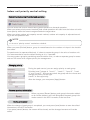
TIPS FOR SAVING ENERGY
ENGLISH
TIPS FOR SAVING ENERGY
Here are some tips that will help you minimize the power consumption when you use the air
conditioner. You can use your air conditioner more efficiently by referring to the instructions
below:
• Do not cool excessively indoors. This may be harmful for your health and may consume more
electricity.
• Block sunlight with blinds or curtains while you are operating the air conditioner.
• Keep doors or windows closed tightly while you are operating the air conditioner.
• Adjust the direction of the air flow vertically or horizontally to circulate indoor air.
• Speed up the fan to cool or warm indoor air quickly, in a short period of time.
• Open windows regularly for ventilation as the indoor air quality may deteriorate if the air conditioner is used for many hours.
• Clean the air filter once every 2 weeks. Dust and impurities collected in the air filter may block the
air flow or weaken the cooling / dehumidifying functions.
!
NOTE
• Lonworks Gateway (Following referred as ACP Lonworks)
ACP Lonworks-Free Volt (PLNWKB000)
ACP Lonworks-AC24V (PLNWKB100)
For your records
Staple your receipt to this page in case you need it to prove the date of purchase or for warranty
purposes. Write the model number and the serial number here:
Model number :
Serial number :
You can find them on a label on the side of each unit.
Dealer’s name :
Date of purchase :
IMPORTANT SAFETY INSTRUCTIONS
3
READ ALL INSTRUCTIONS BEFORE USING THE APPLIANCE.
Always comply with the following precautions to avoid dangerous situations and ensure peak
performance of your product
! WARNING
It can result in serious injury or death when the directions are ignored
! CAUTION
It can result in minor injury or product damage when the directions are ignored
! WARNING
• Installation or repairs made by unqualified persons can result in hazards to you and others.
• Installation MUST conform with local building codes or, in the absence of local codes, with
the Nation Electrical Code NFPA 70/ANSI C1-1003 or current edition and Canadian Electrical
Code Part1 CSA C.22.1.
• The information contained in the manual is intended for use by a qualified service technician
familiar with safety procedures and equipped with the proper tools and test instruments.
• Failure to carefully read and follow all instructions in this manual can result in equipment malfunction, property damage, personal injury and/or death.
Installation
• Any question about the product installation should be asked to the service center or the professional
installation agency.
- It may cause fire, electric shock, explosion or injury.
• Consult the service center or the professional installation agency about reinstalling the installed product.
- It may cause fire, electric shock, explosion or injury.
• Please use the standardized parts.
- It may cause fire, electric shock, explosion, injury, or failure.
• Do not keep or use combustible gas or inflammable material near the product.
- IT may cause fire or electric shock.
• Do not disassemble, repair or modify the product at random.
- It may cause failure of the product.
• Do not install where raindrop can fall.
- It may cause failure of the product.
• Do not install the product at wet place.
- It may cause failure of the product.
• Provided product and adaptor shall only be installed and used inside a building.
- It may cause fire or failure of the product.
*Do not install or use outside.
• Install stably in a place that can endure the weight of the ACP Lonworks.
- If the installation place is not strong enough, the ACP Lonworks may fall and damaged.
• Make sure to enquire to the specialty store of the product purchase or service center for electric works.
- It may cause fire or electric shock.
• Do not damage the power cord or bend it by force.
- It may cause fire or electric shock.
• You need to use a safely insulated power supply which follows IEC61558-2-6 and NEC Class2
- If you do not follow, It may cause fire, electric shock, explosion or injury.
• Do not connetion 220V power to 24V products
- If you do not follow, It may cause fire, electric shock, explosion or injury.
ENGLISH
IMPORTANT SAFETY INSTRUCTIONS
4
SAFETY PRECAUTIONS
ENGLISH
• Do not connect power cord to the control signal connector.
- It may cause fire or explosion.
Operation
• Do not change or extend the power cord with your own discretion.
- It may cause fire or electric shock
• Do not place any heating device near the product.
- It may cause fire.
• Do not use any heating device near the power cord.
- It may cause fire or electric shock.
• Do not let water flow into the product.
- It may cause electric shock or failure.
• Do not put heavy weight on the power cord.
- It may cause fire or electric shock.
• Do not put heavy weight on the product.
- It may cause the failure of the product.
• If the product is flooded, consult the service center or the professional installation agency.
- It may cause fire or electric shock.
• Let the children or the old and the weak be controlled by the guardian to use.
- It may cause accident or failure.
• Do not give any shock to the product.
- Any shock to the product may cause failure.
• Grab the head of the plug of the power cord to pull when disconnecting the plug, and do not touch
the plug with wet hands.
- It may cause fire or to deform the product.
• Do not use the product in certain environments as follows.
- If the product is used in a place with oil, steam, or sulfuric acid gas, performance may be degraded
or product may be damaged.
• Do not press the switch or button with sharp objects.
- It may cause electric shock or failure of the product.
• Please check the operation temperature.
- If the product is used in an environment with the temperature exceeding the operation boundary, it
may cause a severe damage.
Please check the usage temperature boundary in the manual. If there is no specified temperature,
please use the product within the boundary of 0~40°C.
• Do not put a container, etc. with water on the product.
- It may cause fire or electric shock.
• Do not touch the switch with wet hand.
- It may cause electric shock or failure of the product.
• Please read installation and user manual for connection with PC or peripheral devices.
- It may cause fire or failure of the product.
• If a warning window appears on PC, product stops, or it does not work, immediately stop the usage.
- It may cause fire or failure of the product.
• When doing service work or cleaning, please shut off the power to the equipment always.
- It causes the deformation of the product or fire.
! CAUTION
Operation
• Do not use strong detergent such as solvent, but a soft cloth.
- It may cause fire or to deform the product.
• Please check the rated capacity of the power.
- It may cause fire or failure of the product.
TABLE OF CONTENTS
5
ENGLISH
TABLE OF CONTENTS
2
3
6
6
8
9
11
TIPS FOR SAVING ENERGY
IMPORTANT SAFETY
INSTRUCTIONS
ACP LONWORKS FUNCTIONS AND SPECIFICATION
ACP Lonworks Functions
ACP Lonworks Components
Names of each part of ACP Lonworks
ACP Lonworks Hardware Specification
12 Operating ACP Lonworks with
ACCS
12
15
23
24
25
26
27
33
34
37
40
41
43
46
48
51
54
63
64
68
Review the initial ACCS screen
Controlling the Equipments
Ventilation Control Screen and unique features
AWHP Control Screen and unique features
AHU Control Screen and unique features
Chiller Control Screen and unique features
Setting the schedule
Controlling the peak operation ratio
Indoor unit priority control method
Outdoor unit capacity control method
Controlling demand power
Indoor unit priority control method
Outdoor unit capacity control method
Monitoring the equipment status
Reviewing the Error Log
Reviewing the power (power display interface)
Setting the system
Indoor unit priority control setting
Outdoor unit capacity control setting
Additional functions
80
80
82
83
85
86
87
89
89
89
91
92
94
95
96
97
98
98
99
99
102
104
106
107
107
108
109
114
114
115
69 Installing ACP Lonworks
119
69
70
121
71
72
74
75
76
76
78
79
Installing ACP Lonworks
Check points during the ACP Lonworks installation
Setting the indoor unit address
Setting the PI485 and connecting the cable
Installing ACP Lonworks and connecting
cables
Installing the ACP Lonworks in DIN RAIL
Connecting RS-485 cable to the ACP
Lonworks
Fixing the ACP Lonworks to the wall
Connecting Ethernet cable (LAN cable) to the
ACP Lonworks
Connecting LON communication cable(TP/FT10) of ACP Lonworks.
Before configuring the ACP Lonworks environment
Setting the ACP Lonworks network address
Entering into the environment setup mode
How to set network address
Setting IP address
Using dynamic IP using DHCP
Checking ACP Lonworks access
Selecting Peak or Demand
Setting the functions of the ACP Lonworks
Before setting the functions of the ACP
Lonworks
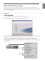
Selecting ACCS display language
Setting whether to use schedule function
Setting whether to use the power display
function
Setting whether to display error history
Setting whether to display cycle information
Setting whether to use FireAlarm function
Setting whether to use air conditioner 0.5°C
control function
Setting whether to use CH6 function
Software service function
Software update
Data backup
Data recovery
RS-485 data logging
Setting the module type of the ACP Lonworks
Before setting the module type of the ACP
Lonworks
Display the module type setting information
Accessing ACP Lonworks
Input indoor/outdoor unit and ventilation
equipment information
When ACP Lonworks is connected to AC
Manager
When ACP Lonworks is not connected to AC
Manager
Verifying and checking the ACP Lonworks
installation
Connecting with Lonworks BMS
122 NOTES
122
126
127
136
148
Troubleshooting
Guide to Open Source Software
Function Block
Control/Monitoring Point List
Network Variables
Ver 1.0.0
6
ACP LONWORKS FUNCTIONS AND SPECIFICATION
ENGLISH
ACP LONWORKS FUNCTIONS AND SPECIFICATION
ACP Lonworks(ACP Lonworks Gateway) is the central controller that can manage up to 64 equipments in one space individually or as combined.
- In case of air conditioner indoor unit, up to 64 indoor units
- In case of AHU unit, up to 16 units
- In case of Chiller unit, up to 15 units
h It is required a separate ACP Lonworks for each other product type(air conditioner, AHU or
Chiller). ACP Lonworks can't to connect air conditioner indoor unit, AHU unit or Chiller unit at
the same time.
ACP Lonworks Functions
Major functions of the ACP Lonworks are as follows.
Environment setting function using the ACP Lonworks external buttons
ACP Lonworks can use the external buttons installed outside of the ACP Lonworks to set the following functions.
- Set Network environment (IP address, Net mask, Gateway)
- Set the function to use between Peak/demand function
- Set the language to use in LG ACCS screen
- Set whether to use schedule function
- Set whether to use integrated power function
- Decide whether to use error history display function
- Decide whether to display outdoor freezing cycle related information
- SW upgrade function
- Data backup function
- Data recovery function
- RS-485 communication logging function
- Set CH6 for chiller interface
- Set the module type
PLNWKB000
PLNWKB000
ACP LONWORKS FUNCTIONS AND SPECIFICATION
7
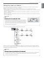
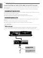
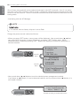
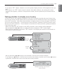
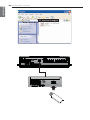
Without an installation of a separate PC program, when IP address of ACP Lonworks is input in
the address window using Internet Explorer, the central control program in ACP Lonworks web
server is automatically run, and the functions of various contents can be used.
Internet
PLNWKB000
Internet
Explorer
- Controlling of up to 64 air conditioner indoor
units
- Monitoring of error and operation status
- Controlling the peak power / demand power
- System setting function
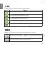
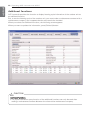
P\\X"! Devices that can interface with ACP Lonworks
Device
ACP Lonworks
AC Ez
O
AC Smart Premium
O
AC Manager Plus
O
Air Conditioner
O
Ventilation
O
AWHP
O
Fire Alarm
O
Chiller
O
AHU
O
ENGLISH
Embedded web server function
8
ACP Lonworks FUNCTIONS AND SPECIFICATION
ENGLISH
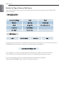
ACP Lonworks Components
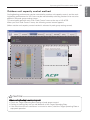
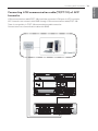
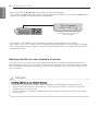
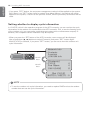
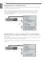
Inside the packaged box of the ACP Lonworks, there are the components as in the following
drawing. Open the packaged box of the ACP Lonworks, and check if all of the corresponding
components are included.
PLNWKB000
INSTALLATION/USER MANUAL
• Make sure to read the cautions for safety before installation and use, and use
it correctly.
• It is intended to keep protect the safety of the installer and user and to
prevent the property damage, etc.
• After reading the user manual, please keep it at a place where user can
access any time.
TYPE : ACP Lonworks (ACP Lonworks Gateway)
MODEL : PLNWKB000, PLNWKB100
P/NO : MFL67842102
ACP Lonworks
(ACP Lonworks Gateway)
www.lg.com
Quick Guide
Power Cord
250V AC, 3A
Power Supply Adaptor
Input: 100~240V
50/60Hz 1.2A
Output: DC 12V
3.33A, 40W MAX
ACP Lonworks
User’s Guide
!
NOTE
• May be different from the image that has been shown and items sold separately parts.
• Power Supply Adaptor and Power Cord are not included in PLNWKB100 (AC24V power use)
ACP LONWORKS FUNCTIONS AND SPECIFICATION
ENGLISH
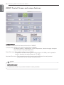
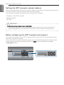
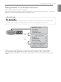
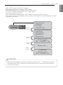
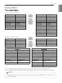
Names of each part of ACP Lonworks
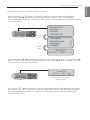
ACP Lonworks is composed as follows.
1
PLNWKB000
2
6
3
5
7
4
9
11
!
12
10
13
NOTE
• No. 3 and No. 4 may be different for each model.
9
8
10 ACP LONWORKS FUNCTIONS AND SPECIFICATION
ENGLISH
1
Cover
Front cover of the ACP Lonworks
2
RS-232 console port
Reserved communication port
3
Adaptor connection jack
Jack for DC 12V to connect to the power supply adaptor (not supported by PLNWKB100)
4
Power port
AC24V port for power connection (not supported by PLNWKB000)
5
Buttons and LCD
Buttons and LCD to set network environment and to display other information
6
Basic external input/output signal connectors
Connection ports to connect to external input/output signals (DI:2, DO:2)
7
RS-485 communication port
RS-485 communication ports to connect to air conditioner and ventilation equipment (4EA)
8
RS-485, LON communication ports and BMS connection button(SERVICE SWITCH)
RS-485 communication ports(2EA) and LON comunication port(1EA)
BMS connection button(SERVICE SWITCH)
9
Mini USB port
USB to Serial port for software debugging
10 USB port
For software update and data backup
11 Power switch
Switch to turn on or off the power of the ACP Lonworks
12 Ethernet port
Ethernet port to connect to internet and AC Manager
13 SD card slot
For RS-485 communication data backup.
! CAUTION
If four times the power connector for the connection, as shown by using the right connection, but please note that an electric shock.
Use the designated parts must be connected to a power source.
※ Connector manufacturers: PHOENIX CONTACT
PartNo: MVSTBR 2,5 / 2-ST-5, 08 2P 5.00MM
ACP LONWORKS FUNCTIONS AND SPECIFICATION
11
ENGLISH
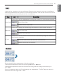
ACP Lonworks Hardware Specification
ACP Lonworks hardware specification is as follows.
Category
Description
Boundary of usage temperature 0°C~40°C
CPU
i.MX515 – 32Bit 800MHz speed
(Option:MPC5668G, 116MHz)
RAM
128MB DDR2 SDRAM * 2EA
ROM
4GB i-NAND Flash
Communication ports
External input/output ports
!
- Ethernet 10 / 100 BASE-T
- USB : USB Host (SW upgrade, data backup)
mini USB Device (Debug)
- RS-485 communication ports 6EA
- Lon communication port 1EA
- SD card slot (RS-485 communication logging)
- RS-232 Console Port (HMI)
- DI, DO
LED
27EA (RS communication status, Ethernet communication
status, power status, operation status)
LCD
20 ×4 Character-LCD (network environment setting and information display)
NOTE
License policy
This product follows GPL (General Public License) for the use of Embedded Linux.
12 Operating ACP Lonworks with ACCS
ENGLISH
Operating ACP Lonworks with ACCS
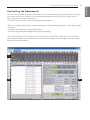
LG ACCS is a UI program of web server that can operate ACP Lonworks.
This chapter explains about the function and process to operate ACP Lonworks using LG ACCS.
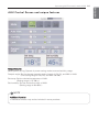
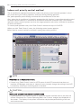
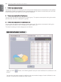
Review the initial ACCS screen
LG ACCS (Advanced Centralized Control System) is a program that is automatically run when you
access to ACP Lonworks web server. The user can control the ACP Lonworks and the equipments using LG ACCS and monitor various status information.
When you access LG ACCS, the following LG ACCS program is executed.
1
2
Operating ACP Lonworks with ACCS 13
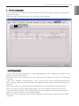
You can select the corresponding menu from the menu selection button to perform the functions
such as control and monitoring, etc.
ACP Lonworks has the following 9 menus.
Category
Description
It can perform the functions of operation status change, lock all, lock temperature, etc. of the equipments connected to the ACP Lonworks.
It can start or stop the equipments connected to the ACP Lonworks
according to preset schedule.
It can set the operation ratio of the entire air conditioner to set the peak
operation ratio to prevent the operation ratio of the air conditioner from
exceeding the set value.
It can use AC Manager to use peak control function.
It can monitor the operation status and error status of the equipments connected to the ACP Lonworks.
It can review the error history occurred in the equipments connected to
the ACP Lonworks.
It can review the power usage used by the equipments connected to the
ACP Lonworks.
It can register, change, or delete the information of the equipments connected to the ACP Lonworks.
It can see the cycle information, etc. of the outdoor unit connected to the
ACP Lonworks. (only if maintenance contract is made with a maintenance
company) Or, you can use the additional functions developed in the future.
ENGLISH
1 Menu selection button
14 Operating ACP Lonworks with ACCS
ENGLISH
2 Peak operation ratio control, network status display window
The running status of peak operation ratio control mode and the air status of the network are displayed with the following icons.
Category
Icon
Description
It is displayed when it is in peak operation ratio control mode.
Peak operation ratio
It is displayed when peak operation ratio control mode is turned
off.
It is displayed when error occurs during network connection.
Network connection status
It is displayed when it is properly connected to the network and
operating.
It is displayed when it is trying to connect to the network.
Operating ACP Lonworks with ACCS 15
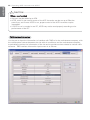
You can use LG ACCS to control the functions such as equipment grouping and selection, operation mode, air flow, air direction, lock, temperature adjustment and stop, etc. (Detail control
menu is different for each equipment.)
LG ACCS control functions have the following advantages.
- With the central control type, you can manage all of the installed equipments using the computer screen.
- Operation and monitoring can be easily done.
- It can be integrated and managed through group setting.
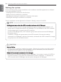
Click ‘Control Group Air Conditioner’ menu at the top of LG ACCS to control the air conditioner.
(This manual explains the air conditioner control as an example, and will explain only the unique
features for other products.)
1
2
3
ENGLISH
Controlling the Equipments
16 Operating ACP Lonworks with ACCS
ENGLISH
1 Air conditioner operation status window
In the air conditioner operation status window, operation status, operation mode, temperature of
the space where the indoor unit is currently installed, and desired temperature of individual air
conditioner are displayed.
Group name & Operation status lamp
At the top of the air conditioner operation status window, the name of the selected group and
the status of individual air conditioner are displayed with the lamps.
The operation status of maximum of 16 air conditioners is displayed in one screen.
Lamp indicates the status of the air conditioner with the color of the lamp. The status of the air
conditioner according to each color is as follows.
Lamp color
Status
Description
(Green)
On
It indicates that the air conditioner is operating normally.
(Gray)
Off
It indicates that the air conditioner is stopped.
Operating ACP Lonworks with ACCS 17
ENGLISH
Mode
In Mode, when the air conditioner is currently in operation, the mode operation is displayed with
an icon.
The operation modes displayed on the screen are as follows.
Type
Icon
Description
It is displayed when the air conditioner is currently in cooling operation.
It is displayed when the air conditioner is currently in dehumidification
operation.
It is displayed when the air conditioner is currently in wind only operation.
Normal
Operation
State
It is displayed when the air conditioner is currently in heating operation.
It is displayed when the air conditioner is currently in peak operation ratio
control state.
It is displayed when the air conditioner is currently in A/I operation.
A/I(Artificial Intelligence) operation is the automatic operation function for
the air conditioner sets the operation mode and air flow by itself according
to the indoor temperature.
It is displayed when an error occurred currently to the air conditioner.
Error State
It is displayed when an error occurred currently due to the network.
Room Temp & Set Temp
In the Room Temp, the temperature of the space where the air conditioner is currently installed
is displayed.
But, if the error indicator lamp is on, the number of the current temperature indicates the error
code, not the temperature.
The desired set in the air conditioner is displayed in the Set Temp. The Set Temp is not displayed
during wind only or dehumidification operation, or in an error state. For ventilation equipment,
Set Temp or Room Temp is not displayed. But, the Set Temp is displayed when the direct cooling type ventilation is set as the master.
18 Operating ACP Lonworks with ACCS
ENGLISH
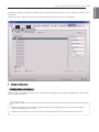
2 Air conditioner group and air conditioner selection window
In the air conditioner group and air conditioner selection window, the list of air conditioner groups
and the air conditioners set in the system is displayed.
Also, you can select an air conditioner group or air conditioner for air conditioner control.
List of air conditioner groups and list of air conditioners
In 'group', the list of air conditioner group set in the ACP Lonworks is displayed. If you select a
particular air conditioner group, the list of the air conditioners that belong to the corresponding air
conditioner group is displayed in ‘air conditioner’ on the right.
If you click the air conditioner group to select from the list, the corresponding group is selected,
and if you click again, the selection of the corresponding group is cancelled. Also, if you click
several groups, you can select several groups at the same time.
In 'air conditioner', the list of the air conditioners that belong to the particular air conditioner
group in the ACP Lonworks is displayed.
To select several air conditioners, drag with the mouse or select an air conditioner while pressing
down ctrl key, or you can select using shift key.
Operating ACP Lonworks with ACCS 19
It displays the air conditioner control setting selected from the list of the air conditioner group and
the air conditioner list to control.
Mode
The operation method of the air conditioner can be set at the mode. The modes to set are as follows:
Icon
Description
It operates the cooling operation. The cooling operation can set the desired temperature to 18°C ~ 30°C
Note: Setting the set temp
Because too much cooling is harmful for health, set the suitable desired temperature.
About 5°C is better for the difference between the indoor temperature and the outdoor temperature. If the set temp is higher than the indoor temperature during the cooling operation,
it does not operate the cooling operation, but the wind only operation.
ItNote:
drivesSetting
the heating
operation.
The heating operation can set the desired temperathe set
temp
ture to 18°C ~ 30°C
The excessive heating is harmful for the health, so set the suitable desired temperature.
About 5°C is better for the difference between the indoor temperature and the outdoor temperature. If the set temp is lower than the indoor temperature during the heating operation,
it does not operate the heating operation, but the ventilation.
The dry eliminates moisture. It can effectively eliminate moisture during the rainy
season or at the high humidity condition. When it is selected, the desired temperature cannot be set.
It circulates the fresh air. The ventilation only may be used in Spring and Autumn.
When it is selected, the desired temperature cannot be set.
AI operation automatically maintains the indoor temperature at its optimal state
according to the indoor temperature.
ENGLISH
3 Control & Monitoring Window
20 Operating ACP Lonworks with ACCS
ENGLISH
Fan Speed
It controls the air flow. The types of air flow to set are as follows:
Air flow
Description
It sets to ventilate with a small of air flow.
It sets to ventilate at the medium level of air flow.
It sets to ventilate at the high level of air flow.
It sets to automatically ventilate at the suitable level of air flow for the environment
with the indoor unit installed.
It sets to ventilate with the maximum air flow.
(It only appears when ventilation product is selected.)
Auto Swing
It sets the air direction of the current air conditioner to Up & down or Left & right.
Icon
Description
It executes the air direction operation of the air conditioner.
It stops the air direction operation of the air conditioner.
Operating ACP Lonworks with ACCS 21
ENGLISH
Lock
It sets the lock function of the air conditioner. When the lock function is set, the air conditioner
cannot be controlled by the wireless or wired remote controller. Use the lock function not for the
user individually, but to centrally control the air conditioner.
Type
Icon
Description
Control not to set the temperature by using the wireless or wired remote controller.
Temp Lock
Set the Temp Lock.
Deselect the set Temp Lock.
Control not to change the mode using the wireless or wired remote controller.
Mode lock
Set the mode lock.
Deselect the mode lock.
Control not to set the entire function of the air conditioner by using the wireless or
wired remote controller.
All Lock
Set the All Lock function for the entire air conditioner.
Deselect the set All Lock function.
Set Temp
Set the desired indoor temperature of the air conditioner.
The desired temperature can be set by clicking ▲ button or ▼ button.
The desired temperature can be set for both the cooling and the heating with the range of
18°C~30°C.
Click (°C) symbol to switch to (°F) for displaying the temperature. The Set Temp can be set in
Fahrenheit with the range of 64°F~86°F.
22 Operating ACP Lonworks with ACCS
ENGLISH
Temp. Range
Set the maximum/minimum temperature limit of the indoor where air conditioner is installed.
The maximum/minimum temperature can be set by clicking ▲ button or ▼ button.
The maximum temperature can be set with the range of 18°C~30°C, and the minimum temperature can be set with the range of 16°C~30°C.
Maximum temperature cannot be lower than the minimum temperature.
! CAUTION
Desired temperature & temperature limit
• The desired temperature is automatically changed when temperature limit range is changed
to prevent going outside the temperature limit range.
• Since the desired temperature range is 18°C~30°C, even if the minimum temperature of
temperature limit is 16°C, the desired temperature cannot go under 18°C.
Running & Stopping the operation
Click Run or Stop button to start or stop the air conditioner.
Button
Description
Operate the air conditioner according to the set value.
Stop the operating air conditioner.
!
NOTE
When a stopped indoor unit does not perform the central control command
• Some old model indoor units may not follow the central control command while it is not in operation.
• Therefore, you can order while it is in operation.
• For example, to change the set temperature and air direction of a stopped indoor unit, the set
temperature and air direction of the corresponding indoor unit may not be changed. In such case, if
you change the set temperature and air direction while the corresponding indoor unit is in operation, it
will be reflected properly to the indoor unit.
• With the same principle, for some indoor units, when the indoor unit in cooling operation with set air
direction is stopped, the air direction is stopped. And if the user starts the corresponding indoor unit
without setting air direction, the Auto Swing still remains at stopped state.
Operating ACP Lonworks with ACCS 23
Unique features
Mode
Heat
Exchange
Set both air intake and discharge to ventilate through electric heat
exchanger. (It is used in Summer/Winter when there is a big difference
of temperature and humidity between indoor and outdoor.)
Normal
Set the discharged air to ventilate without going through electric heat
exchanger. (It is used in Spring/Fall when there is a small difference of
temperature and humidity between indoor and outdoor.)
Auto
Measure the temperature of indoor and outdoor and automatically set
the temperature to maintain the optimal state. (It automatically controls
air intake and discharge to maintain uniform balance of the indoor air.)
Execute the power saving operation function. (Power saving operation
Power savoperates by finding the most efficient state of the ventilation equipment
ing
to save power consumption.)
Quick
Execute Quick ventilation function. (Rapid ventilation is the operation to
prevent the contaminated air or humidity of one room from spreading to
another room.)
Heater
Execute heater function. (Heater function is the operation to supply
warm air during Winter when the air outside is cold.)
Humid
Execute Humid function. (Humidification function is the operation to
increase humidity when the air is too dry.)
Options
※ Humid can only be turned on when the operation mode of the direct cooling type ventilation is
in heating mode.
!
NOTE
Additional function
• Additional function may not be included in some products.
ENGLISH
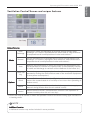
Ventilation Control Screen and unique features
24 Operating ACP Lonworks with ACCS
ENGLISH
AWHP Control Screen and unique features
Unique features
Heat tank: Turn on/off the Heat tank function of AWHP.
Current temp: Display the current temperature of AWHP.
(It displays water in temperature, room temperature, heat tank supply temperature, and solar heating temperature.)
Room Set temp: Set the Room Set temp of AWHP.
(If operation mode is cooling, the setting range is 16~30°c, and if operation
mode is heating, the setting range is 18~30°c.)
Heat tank Set temp: The temperature setting range may be different for each product.
Please refer to the manual of each product.
!
NOTE
Additional function
• Additional function may not be included in some products.
Operating ACP Lonworks with ACCS 25
Unique features
Mode power saving: Operate in power saving mode to save electricity usage.
Damper angle: Set the damper opening angle of each of OA, EA, and MIX of AHU.
(The setting range of OA, EA, and MIX is 0~90.)
Set temp: Set the desired temperature of AHU.
(Setting range is 18~30°c.)
Set humidity: Set the desired humidity of AHU.
(Setting range is 40~60%.)
!
NOTE
Additional function
• Additional function may not be included in some products.
ENGLISH
AHU Control Screen and unique features
26 Operating ACP Lonworks with ACCS
ENGLISH
Chiller Control Screen and unique features
Unique features
Alarm: Display cycle number and error number of the Chiller with error.
Setting: Set cooling temperature, heating temperature, and demand limit ratio of Chiller.
(Setting range of cooling temperature is 5~15°c, setting range of heating temperature is
40~55°c, and setting range of demand limit ratio is 0~100%.)
Chilled Water: Display Leaving, Entering, and ambient of the Chiller.
!
NOTE
Additional function
• Additional function may not be included in some products.
Operating ACP Lonworks with ACCS 27
It is the function to perform the reserved operation at the specified time by specifying the operation of the air conditioner. For example, for the case of the school, the air conditioner automatically starts and stops at the specified time by setting the schedule to attending school and returning
home.
The unnecessary operation and management cost of the air conditioner can be reduced by this
schedule function, and it can effectively save the energy because it is used only when necessary.
Schedule can be set by logging in as super user or manager.
! CAUTION
Saving after the system setup
• When ‘group setting completed’ button is pressed in ‘system setting’ menu, all schedule
information currently set will be initialized, so be careful.
Time of ACP Lonworks
• When a user access ACP Lonworks through web browser, the time of PC and ACP
Lonworks are automatically synchronized, and ACP Lonworks executes schedule function
based on this time. Therefore, always maintain the time of PC to be the current time.
!
NOTE
Schedule maintenance time
• When setting the schedule, 1~3 minute schedule setting is maintained for time the actual
schedule is set.
• For example, when you set the schedule for the unit to be turned off at 5:00, the operation
is turned off from 5:00 to 5:03. Therefore even when you try to operate the unit with the
wired remote controller, it may be turned off.
ENGLISH
Setting the schedule
28 Operating ACP Lonworks with ACCS
ENGLISH
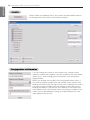
To set the schedule, click ‘Schedule’ menu at the top of LG ACCS. When you click ‘Schedule’
menu, the schedule setting screen appears as follows.
1
2
3
1
Calendar window
Basically, this month’s calendar is displayed, and today is highlighted.
Operating ACP Lonworks with ACCS 29
Schedule list
The entire list of the set schedule is displayed. If you select certain day from the calendar,
the schedule activated on that day will be displayed in bold and blue letters.
If you select a schedule from the schedule list, the contents of the schedule are displayed as in
the following screen.
If a schedule saved with different manager ID is selected, the schedule name is displayed in red
as in the following screen.
ENGLISH
2
30 Operating ACP Lonworks with ACCS
ENGLISH
3
Command button
Each button has the following meanings.
Button
Query/Modify
Add
Delete
Description
Show the contents of the selected schedule and display a new window for
edition
Add a new schedule
Delete the selected schedule
Add
When add schedule button is pressed, the following screen appears.
! CAUTION
• Please be aware that, if the schedule for the same equipment is registered with different
control commands for the same time, schedule may not run properly.
Example) Schedule1: 2011. 1. 1 1PM Indoor No. 00, 01, & 02 Cooling mode
Schedule2: 2011. 1. 1 1PM Indoor No. 00, 01, & 02 Heating mode
Schedule3: 2011. 1. 1 1PM Indoor No. 00, 01, & 02 Automatic mode
• As above, if 3 duplicate schedules are applied, any schedule can be applied to each of the
equipment.
Operating ACP Lonworks with ACCS 31
Description
Schedule Name
Nickname[Memo]
You can take a memo or make name for easy to memorize the schedule.
Repeated pattern
You can set the repeated pattern of the schedule.
If you select ‘day of week selection’, you can set the schedule to operate
only on the desired day of the week.
If you select ‘once’, the schedule operates once on the selected day and
time.
If you select ‘everyday’, the schedule operates everyday during the
selected period.
If you select ‘Mon.~Fri.’, the schedule operates on Monday ~ Friday during the selected period.
If you select ‘Mon.~Sat.’, the schedule operates on Monday ~ Saturday
during the selected period.
Period
Command
Configuration
You can set the schedule operation time in the units of 10 min. within
00:00 ~ 23:50.
It sets the control command.
It sets the control command for each of the equipment.
You can change only the desired attributes
Select units to apply It selects the equipment to apply the schedule.
the Schedule
You can select a group or individual equipment.
ENGLISH
Button
32 Operating ACP Lonworks with ACCS
ENGLISH
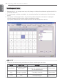
View/Change and Delete
1. Manager who is not a super user may only change or delete the schedules registered with his
or her own account.
2. To view/change or delete a schedule, the schedule shall be first selected as in the following
picture.
3. If you press view/change button, the previously added schedule information is displayed.
It can be changed with the same method as adding schedule.
If you press delete button, the selected schedule will be deleted from the list.
!
NOTE
• There are schedule setting authorities as follows according to user class.
Button
Query/Modify
Add
Delete
Super User
Manager
User
Can view all schedules
Can view or change
Can change the schedule created with
all schedules
the corresponding ID
No authority
Can add a schedule
No authority
Can add a schedule
Can delete all sched- Can delete schedules created with the
ules
corresponding ID
No authority
Operating ACP Lonworks with ACCS 33
It maintains the consumed power to be kept lower than or equal to the target power by monitoring the power consumption of the air conditioner. Peak operation ratio control function can control with two methods according to the set peak operation rules to save energy.
The first is to stop or operate with wind only operation in turn to satisfy the peak operation ratio
set by the user, and the second is to adjust the cooling/heating performance of the outdoor unit
without stopping the indoor unit operation to satisfy the peak operation ratio.
Peak operation ratio control function has the following advantages:
- Centrally control all installed air conditioners by using the computer screen.
- Monitor and control the peak operation ratio for 24 hours a day.
- Easily perform controlling and monitoring.
- Set the peak control function operation ratio (%).
- Control the operation switching period (5~15 minutes) of the air conditioner.
- Set the peak group to give priorities of 5 stages for each group
(Priorities have 5 stages of very low, low, normal, high, and very high, and the very low is the
first controlled group.)
!
NOTE
Changing the operation type
• Please refer to ‘page 62’ peak group setting for the change of indoor unit priority and
outdoor capacity control method of peak operation ratio control function.
! CAUTION
When ACP Lonworks interfaces with AC Manager
• When the ACP Lonworks is interconnected with the AC Manager, set Demand as ACP
Lonworks setting.
• The ACP Lonworks operates according to the demand setting of the AC Manager.
When cooling/heating is not running well
• Check the desired operation ratio setting of the peak power control.
• Cooling or heating may not run well according to the desired operation ratio.
ENGLISH
Controlling the peak operation ratio
34 Operating ACP Lonworks with ACCS
ENGLISH
Indoor unit priority control method
The air conditioner operated forcefully by indoor unit priority control method operates in wind
only mode during the cooling operation, and stops during heating operation.
But, peak operation period setting minimized the inconvenience of the user.
Also, when the air conditioner is forcefully operated by this function, it uses the automatic control
of central control method, so individual air conditioner cannot be controlled. But, if the current
operation status uses the power less than the target operation ratio value, individual air conditioner can be controlled.
To control peak operation ratio, click ‘Peak Control’ menu at the top of LG ACCS.
When you click ‘Peak Control’ menu, the following control screen appears.
(When priority control method is selected in peak group setting screen)
1
3
2
!
NOTE
When there is no Peak Control menu
• If there is no ‘Peak Control’ menu in ACCS menu of the ACP Lonworks that does not
interface AC Manager, and there is ‘demand’ menu instead, change the setting of the ACP
Lonworks by referring to ‘selecting peak or demand’.
! CAUTION
When peak operation ratio control function is used
• If peak operation ratio control function is used, the function shall be used or set after the
current information for ‘Current Operating Rate’ and ‘Current’ category are displayed on
the screen. The display of the power information may be delayed according to the network environment.
Operating ACP Lonworks with ACCS 35
Power consumption monitor
The peak control setting information and the operation information are displayed in the power
consumption monitor.
- Function operation status
- Current operation Rate
- Target Operating Rate
- Cycle
Function operation status
The operation status of the current peak control is displayed in the function operation status.
The types of the displayed operation status are as follows.
Operation status
Description
Peak operation ratio control function is in operation.
It is displayed when peak operation ratio control function is stopped.
Current power consumption and Current Operation Rate
“Current Operation Rate” displays at what % is the power consumption of the currently operated air conditioner compared to all air conditioners.
Desired power consumption and Target Operating Rate
“Target Operating Rate” displays at what % is the power consumption to be permitted by the user compared to all air conditioners.
Cycle
It displays the period to stop the peak operation.
For example, if it is set to 5 min. period, the air conditioners operate at peak operation every 5 min. are converted to adjust all air conditioners to stop at the same time.
Operation conversion period may be adjusted in the range of 5 min. ~ 15 min.
ENGLISH
1
36 Operating ACP Lonworks with ACCS
ENGLISH
2
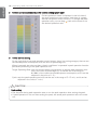
Current operation status and power control setting (graph type)
Current operation status is displayed in the left side of
the peak operation control screen, and there is a graph
that can set power control function. To change the peak
operation ratio, you can drag mark with mouse to set
the desired operation ratio.
3
Power control setting
On the right side of the peak operation control screen, there is a setting category that can set
the desired power consumption with the units of percentage (%).
When it exceeds the value set here, the air conditioner is operated in peak operation function
periodically according to the peak operation rule.
Target Operating Rate: sets the desired power consumption to operate peak operation function in the units of percentage (%). (It can be set in the range of
0~100% of the maximum possible power consumption, and it can be
adjusted in the units of 1 %.)
Cycle: sets the peak operation period (It can be set in the range of 5~15 min., and it can be
adjusted in the units of 1 min.)
! CAUTION
Peak setting
• Set the peak during peak operation state or run the peak operation after setting the peak.
• If peak operation is not run after setting the peak, the actual peak operation ratio will not be
set.
Operating ACP Lonworks with ACCS 37
Cooling/heating performance may be controlled by outdoor unit capacity control, and the cooling/heating performance for VIP room may be maintained by selecting outdoor units not to be
applied in the peak group setting screen.
To control peak operation ratio, click ‘Peak Control’ menu at the top of LG ACCS.
When you click ‘Peak Control’ menu, the following control screen appears.
(When outdoor unit capacity control method is selected in peak group setting screen)
1
3
2
! CAUTION
When cooling/heating is not running well
• Check the Target Operating Rate setting of peak power control.
• Cooling or heating may not run well because of the Target Operating Rate.
• If the wind from the air conditioner is not cool or warm, raise the Target Operating Rate or
stop peak operation.
ENGLISH
Outdoor unit capacity control method
38 Operating ACP Lonworks with ACCS
ENGLISH
1
Operation status monitor
Peak control setting information and operation information are displayed in operation status
monitor.
Function operation information
The current demand control operation status is displayed in the function operation status.
The types of the displayed operation status are as follows.
Operation status
Description
Peak operation ratio control function is in operation.
It is displayed when peak operation ratio control function is stopped.
Desired power consumption and Target Operating Rate
“Target Operating Rate” displays at what % is the power consumption to be permitted by the user compared to all air conditioners.
Operating ACP Lonworks with ACCS 39
Operation ratio control setting (graph type)
There is a graph that can set the peak operation ratio control function.
To change the peak operation ratio, you can drag ◀ mark with mouse to set the Target
Operating Rate.
The operation ratio of the outdoor capacity control method can be set to the following 9
stages.
9 stages of the operation ratio: 0, 40, 45, 50, 60, 70, 80, 90, 100%
3
Power control setting
On the right side of the peak operation control screen, there is a setting category that can set
the desired power consumption with the units of percentage (%).
It controls the performance of the outdoor unit not to exceed the value set here.
Desired operation ratio: sets the desired power consumption to run the peak operation function in the units of percentage (%).
(9 stages of the operation ratio: 0, 40, 45, 50, 60, 70, 80, 90, 100%)
! CAUTION
Peak setting
• Set the peak during peak operation state or run the peak operation after setting the peak.
• If peak operation is not run after setting the peak, the actual peak operation ratio will not be
set.
ENGLISH
2
40 Operating ACP Lonworks with ACCS
ENGLISH
Controlling demand power
It maintains the consumed power to be kept lower than or equal to the target power by monitoring the power consumption of the air conditioner.
It can control to save the energy by using the AC Manager connected to the ACP Lonworks to
forcefully start or stop the air conditioner.
It has the following advantages:
- Precise management by controlling the automatic operation ratio of the air conditioner by AC
Manager is possible.
- Monitor and control the peak power for 24 hours a day.
- Easy controlling and monitoring.
Operating ACP Lonworks with ACCS 41
The air conditioner forcefully operated by demand power control function operates in wind only
mode during cooling operation, and stops during heating operation.
But, even if the air conditioner operation is changed by forced operation, it operates in a way that
the user does not feel the change in terms of the effect of the cooling or heating.
While the air conditioner is forcefully operated by demand power control function, it uses the
automatic control of the central control method, air conditioner cannot be operated individually.
But, if the current operation state uses the power under the target operation ratio setting value,
air conditioner can be individually controlled.
To control demand power, click ‘Demand’ menu at the top of LG ACCS.
When you click ‘Demand’ menu, the following demand power control screen appears.
! CAUTION
When there is no demand menu
• When there is no ‘demand power’ menu in ACCS menu, and instead, there is a ‘Peak
Control’ menu, the ACP Lonworks setting is set to use peak control function. To use
demand power function, change the setting of the ACP Lonworks by referring to ‘selecting
peak or demand’.
ENGLISH
Indoor unit priority control method
42 Operating ACP Lonworks with ACCS
ENGLISH
1
Power consumption monitor
The demand control setting information and the operation information are displayed in the
power consumption monitor.
- Function operation status
- Current operation Rate
- Target Operating Rate
- Cycle
Function operation status
The operation status of the current demand control is displayed in the function operation status.
The types of the displayed operation status are as follows.
Operation status
Description
Demand control function is in operation.
It is displayed when demand control function is stopped.
Current power consumption and current operation rate
“Current operation rate” displays at what % is the power consumption of the currently operated air conditioner compared to all
air conditioners.
Desired power consumption and Target Operating Rate
“Target Operating Rate” displays at what % is the power consumption to be permitted by the user compared to all air conditioners.
Cycle
It displays the period to stop the peak operation.
For example, if it is set to 5 min. period, the air conditioners operate at peak operation every 5 min. are converted to adjust all air conditioners to stop at the same time.
Operating ACP Lonworks with ACCS 43
Cooling/heating performance may be controlled by outdoor unit capacity control, and the cooling/heating performance for VIP room may be maintained by selecting outdoor units not to be
applied in the peak group setting screen.
To control demand, click ‘Demand’ menu at the top of LG ACCS.
When you click ‘demand’ menu, the following control screen appears.
(When outdoor unit capacity control method is selected in peak group setting screen)
1
2
ENGLISH
Outdoor unit capacity control method
44 Operating ACP Lonworks with ACCS
ENGLISH
1
Operation status monitor
Demand control setting information and operation information are displayed in operation status monitor.
Function operation information
The current demand control operation status is displayed in the function operation status.
The types of the displayed operation status are as follows.
Operation status
Description
Demand control function is in operation.
It is displayed when demand control function is stopped.
Desired power consumption and Target Operating Rate
“Target Operating Rate” displays at what % is the power consumption to be permitted by the user compared to all air conditioners.
Operating ACP Lonworks with ACCS 45
Operation ratio control setting (graph type)
It displays the operation ratio controlled by the
demand controller.
The operation ratio of the outdoor capacity control
method is set to the following 9 stages.
9 stages of the operation ratio: 0, 40, 45, 50, 60, 70,
80, 90, 100%
! CAUTION
Demand control setting
• Demand control is set by the AC Manager connected outside, so the categories such as
desired operation ratio, operation conversion period, etc. may not be set in LG ACCS program.
When cooling/heating is not running well
• Set the desired operation ratio to be above 70~80% in AC Manager. Otherwise, cooling or
heating may not run well.
ENGLISH
2
46 Operating ACP Lonworks with ACCS
ENGLISH
Monitoring the equipment status
You can see the operation status and the error status of each of the equipment set in all air conditioner groups at the LG ACCS at a glance.
In order to view the status information of the equipment, click 'Monitoring' menu at the top of
the LG ACCS.
When you click 'Monitoring' menu, the following monitoring screen is displayed.
! CAUTION
Air conditioner communication error
• If communication errors occur in multiple air conditioners in the monitoring screen,
demand control cannot be performed and may exceed the contract power.
Operating ACP Lonworks with ACCS 47
Item
Name
Operation mode
Air flow
Air direction
Lock all
Temperature lock
Mode lock
Indoor temperature
Desired temperature
Description
Name of equipment currently registered at the system
Operation mode set in the equipment
The strength of the air of the supported equipment
Whether the air direction is set in the supported equipment
Whether lock all function is set
Whether temperature lock function is set
Whether mode lock function is set
Indoor temperature of the supported equipment
Desired temperature of the supported equipment
Maximum temperature
Maximum temperature of the air conditioner.
The range of the maximum temperature is 18~30°C.
Minimum temperature
Minimum temperature of the air conditioner.
The range of the minimum temperature is 16~30°C.
Operation Stop
Remark
Operation status of the equipment
The error code is displayed if the error is occurred.
- Network Error: NE
- System Error: SE
ENGLISH
The following information is displayed at the monitoring screen.
48 Operating ACP Lonworks with ACCS
ENGLISH
Reviewing the Error Log
The LG ACCS saves and records the information of the error occurred from all equipments connected to the ACP Lonworks.
You can see this error history at ' Error Log' menu of the LG ACCS.
In order to view the error history of the equipment, click the ‘Error Log’ menu at the top of the
LG ACCS.
When you click ' Error Log' menu, the following error history screen is displayed.
2
1
3
Operating ACP Lonworks with ACCS 49
ENGLISH
1
Querying the Error Log
You can set and query the information about the error
occurred within the desired period.
The start date and the end date of the period to query
can be set by pressing each calendar button
within
the query period.
After setting the query period, when you click the [Query]
button
, the information about the error occurred
within the period is displayed.
2
Saving and Printing
[Delete chosen errors] button is used to completely delete the error displayed in the error history
list within the system.
After selecting the error in the error history list and deleting it by pressing the button, when you
press [confirm] button, the corresponding error will be completely deleted from ACP Lonworks.
If you don’t press [confirm] button after deleting an error by pressing [Delete chosen errors] button, it will be erased from the current screen, but it will show again in the future error query.
When you press [Save] button, the queried error history can be saved as the file with the Excel
format.
50 Operating ACP Lonworks with ACCS
ENGLISH
3
Error log list
It displays the history list of the errors occurred within the query period.
The following information is displayed in the error history list.
Item
Description
History of the occurrence and normalization of an error
Icon
Error occurred in the network
Error occurred in the system(outdoor and indoor unit)
Occurrence Date Date when the error was occurred
Occurrence Time Time when the error was occurred
Unit Name
Name of the equipment with error
Error code
Code number of the occurred error
Detail lnfo
Description of the occurred error
Operating ACP Lonworks with ACCS 51
ENGLISH
Reviewing the power (power display interface)
The LG ACCS offers the power display interface function to check and manage the power of all
indoor units of the air conditioners connected to the ACP Lonworks. If this function is used,
when the outdoor unit is shared in officetel, residential-commercial building, and school, it can be
effectively controlled since the power consumption of each indoor unit is displayed.
Because the power display interface function remotely reads the power consumption without the
separate inspection program, it can easily check the power consumption on which the billing can
be done.
In order to use the power display interface function to check the power consumption, click
‘Wattmeter’ menu at the top of LG ACCS. When you click ‘Wattmeter’ menu, the following
power screen appears.
4
1
2
3
5
52 Operating ACP Lonworks with ACCS
ENGLISH
1
Power consumption monitor
At the top, the result of summing all the current accumulated power consumptions of the power
distribution indicator connected to the air conditioners and the power consumed by the air conditioners during the query period at the right are displayed.
2
Power consumption list of each group
You can view the power consumption of each group. The power consumption during the certain
period set by the user is displayed in groups.
3
Power consumption list for each indoor unit
You can view the power consumption of each indoor unit. The power consumption during the
certain period set by the user is displayed for each indoor unit.
The detail meanings of each category are as follows.
Detail history of each air conditioner
When you click
played.
Button, the following detail history for each individual air conditioner is dis-
You can also view daily usages in addition to the accumulated usages of each individual air conditioner in individual air conditioner detail history.
Operating ACP Lonworks with ACCS 53
Printing and saving
You can output the power of each group or each indoor unit displayed on the screen to a printer,
or save as an Excel file.
5
Setting the power consumption query period
You can set the period for query of the power consumption in the right side of "Wattmeter"
screen.
Monthly Enquiry
Monthly Enquiry is the function to view the usage from
the base date set by the user up to today.
History Lookup
History Lookup is the function for the user to select and
view the period of up to 3 months from today.
If you click the query button, the power consumption
during the set period is displayed on the screen.
ENGLISH
4
54 Operating ACP Lonworks with ACCS
ENGLISH
Setting the system
For the following cases, the air conditioner or the ventilator should be registered at or deleted
from the system by LG ACCS.
- Installing the ACP Lonworks for the first time
- Adding a new air conditioner or ventilator
- Changing the existing air conditioner or ventilator information
- Deleting the existing air conditioner or ventilator
The air conditioner can be registered or deleted in 'Setting' menu of LG ACCS.
!
NOTE
Setting group name when the ACP Lonworks interfaces with AC Manager
• The ACP Lonworks and AC manager has different group management boundaries, so if
group name is changed and saved in AC Manager, it is not reflected to the ACP Lonworks,
and the default value is saved in the ACP Lonworks.
(In case of AC Manager Plus, ACP Lonworks group name can be set as set AC Manager
Plus group name.)
Therefore, to change the group name of the ACP Lonworks, first save the setting
information in AC Manager, send the information, and access the ACP Lonworks to change
the group name with the desired name.
! CAUTION
System Setting
• 'Setting menu' is used for installing the product. Because the product should be installed
by the professional engineer with knowledge on the air conditioner, the user should not
operate this menu with his or her own discretion.
When ACP Lonworks interfaces with AC Manager
• When the ACP Lonworks interfaces with AC Manager, if the system is set by LG ACCS of
the ACP Lonworks, it may cause the malfunction of the air conditioner. To interface the
ACP Lonworks with AC Manager, set the system through the AC Manager.
Operating ACP Lonworks with ACCS 55
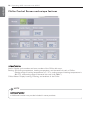
1
1
2
Group Configuration
Locking indoor unit address
When indoor unit address lock is set, central control address cannot be changed from the indoor
unit remote controller.
! CAUTION
• Beware that the central control address cannot be changed from the remote controller
when the address lock is set.
• Address lock function is limited to some indoor/outdoor units and remote controllers.
ENGLISH
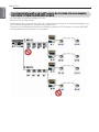
In order to register, delete or modify the air conditioner at the system, click 'Setting' menu of the
LG ACCS.
When you click ' Setting' menu, the following system setup screen is displayed.
56 Operating ACP Lonworks with ACCS
ENGLISH
Installation
When indoor unit address lock is set, central control address cannot
be changed from the indoor unit remote controller.
Changing outdoor unit information
You can change the name of the outdoor unit, central control
address, outdoor unit capacity, and the number of the connected
indoor units. After changing the information, you must press
[Apply] button.
When you change the number of the connected indoor units, if
you input a smaller number than the number of the indoor units
already connected, the last input indoor unit is deleted first, and if
you input a larger number than the number of the indoor units
already connected, it will ask the first address of the indoor unit
to be added, and it will add the indoor units by the number of the
indoor units to be added by finding an empty address from the
input address one by one.
Operating ACP Lonworks with ACCS 57
You can change the name of the indoor unit, central control
address, and indoor unit capacity. After changing the information, you must press [Apply] button.
! CAUTION
Outdoor unit and indoor unit capacity
• When peak/demand control function is used, the indoor unit capacity must be input in the
units of Watt.
• The air conditioner power consumption can be controlled not to exceed the set value
through this value.
Indoor unit power consumption marking method (unit: Watt)
• Power consumption of nth indoor unit =
(Outdoor unit power consumption + Total power consumption of
the indoor unit) x power consumption of nth indoor unit
Total power consumption of indoor unit
Add/delete outdoor unit
To add an indoor unit, press [Add an outdoor] button.
Add outdoor unit, and change outdoor unit information as necessary.
Input the number of the connected indoor units, and when [Apply] button
is pressed, it will ask the first address of the indoor unit to be added, and
it will add the indoor units by the number of the indoor units to be added
by finding an empty address from the input address one by one.
When you select an outdoor unit and press [Outdoor delete] button, the
corresponding outdoor unit will be deleted.
At this time, the indoor units connected to the selected outdoor unit will
be deleted as well.
ENGLISH
Changing indoor unit information
58 Operating ACP Lonworks with ACCS
ENGLISH
Add/delete indoor unit
When you add or delete indoor unit, you can do it by changing
the number of the connected indoor units connected to the outdoor unit, but when you add or delete one by one, you can also
do it by right click and popup menu.
When you press [Add an air-conditioner] button in the popup
menu, air conditioner indoor unit will be added.
Add ventilator / direct cooling type ventilator
To add a ventilator or direct cooling type ventilator, you shall first
add ventilator / direct cooling type ventilator group.
After adding ventilator / direct cooling type ventilator group and
input of the number of ventilator and direct cooling type ventilator
products, press [apply the changes] button.
Or, as in the case of adding air conditioner, you can add the ventilator or direct cooling type ventilator product one by one through
the popup menu. Ventilator or direct cooling type ventilator may
be added under ventilator / direct cooling type ventilator group.
Add AWHP
To add AWHP, right click, and add through the popup menu.
When you press [Add an AWHP] button in the popup menu,
AWHP will be added. AWHP may be added only under outdoor
unit group.
Operating ACP Lonworks with ACCS 59
To add AHU, right click, and add through the popup menu. When
you press [Add an AHU] button in the popup menu, AHU will be
added. AHU is added independently without going under outdoor unit group or ventilator / direct cooling type group.
Add Chiller
To add Chiller, right click, and add through the popup menu.
When you press [Add a Chiller] button in the popup menu, Chiller
will be added. Chiller is added independently without going
under outdoor unit group or ventilator / direct cooling type group.
!
NOTE
• The sum of the connected equipments may not exceed 64.
- In case of air conditioner indoor unit, up to 64 indoor units (air conditioner indoor unit,
ventilator, direct cooling type ventilator and AWHP.)
- In case of AHU unit, up to 16 units
- In case of Chiller unit, up to 15 units
※It is required a separate ACP Lonworks for each other product type. (ACP Lonworks can't
to connect air conditioner indoor unit, AHU unit or Chiller unit at the same time.)
ENGLISH
Add AHU
60 Operating ACP Lonworks with ACCS
ENGLISH
Auto search
When you first register indoor unit / outdoor unit /
ventilator, etc., it is convenient if you use the
automatic search function.
When you press automatic search button, it
searches the indoor unit and ventilator products
connected to the ACP Lonworks.
It takes about 5~10 min. for automatic search.
Moving indoor unit
You can select indoor unit and move to another outdoor unit. When you move an indoor unit,
click one indoor unit with the mouse, and drag it onto another outdoor unit.
·
Operating ACP Lonworks with ACCS 61
When you press [Smart Group Setting] button, the control group is
automatically created based on the outdoor unit and ventilator group
information input in the installation status.
Users may change the control group as they wish as necessary.
·
Installation status
Control Group
Recovery of previous information
If you press [Revert] button, the group information edited so far
is deleted, and it brings back the group information saved in the
ACP Lonworks at the last time.
Completing group setting
When the changes of the information in installation status are completed, you must press [save]
button to save the edited information in the ACP Lonworks. If you press [cancel] button, the
screen will be closed, and the changed information will not be saved.
After changing the information of the installation status, you must change the information of the
peak group and the group information as well.
ENGLISH
Smart Group Setting
62 Operating ACP Lonworks with ACCS
ENGLISH
Peak Group
During the peak control, you can control with priority for each
group. To set the peak group, press [Peak Group] button, and
the following screen will appear.
In this screen, you can select peak operation method, and for priority control method, set peak
group to set the priority of each group.
For outdoor capacity control method, you can set the outdoors that the peak control is not
applied to.
Operating ACP Lonworks with ACCS 63
Control method during Peak/demand operation
You can select the control method during peak operation or demand operation.
When you select priority control method, peak mode operation will start from the indoor unit with
lower priority when the current usage exceeds the target value.
When you select outdoor unit capacity control method, outdoor unit capacity is adjusted according to the set operation ratio.
!
NOTE
• It is set to ‘priority control’ method as a default.
When you press [Default] button, group is created based on the outdoor unit input in the installation status.
For peak control to operate effectively, it is best to create the group in the units of outdoor unit.
It is recommended to use the default setting as it is, if possible.
You may create a group by combining several outdoor units, or make a separate group for cases
such as VIP rooms with a higher priority for management.
Changing priority
During the peak control, you can assign priority to each group.
Priorities have 5 stages of “Level 1”, “Level 2”, “Level 3”, “Level
4”, and “Level 5”, and you can select the group with the mouse and
change the priority on the right.
(Level 5 is the top priority)
After the change, you must press [Apply] button.
Recover previous information
When you press [Revert] button, peak group information edited
so far will be deleted, and it will bring back the peak group information saved in the ACP Lonworks at the last time.
Saving and cancel
When the change of peak group is completed, you must press [save] button to save the edited
information in the ACP Lonworks.
If you press [cancel] button, the screen will be closed, and the changed contents will not be
saved.
ENGLISH
Indoor unit priority control setting
64 Operating ACP Lonworks with ACCS
ENGLISH
Outdoor unit capacity control setting
When you select outdoor unit capacity control, it will convert to the above screen.
The control is performed in the units of outdoor unit in outdoor unit capacity control method, so a
separate group cannot be set.
However, considering various usages, you can set outdoor units that the capacity control is not
applied to, for separate management of the cases such as VIP rooms.
Changing whether to apply
User may decide whether to apply capacity control by selecting the
corresponding outdoor unit as in the figure.
After the change, you must press [Apply] button.
Operating ACP Lonworks with ACCS 65
General Configuration
You can add user ID in addition to the installation information or group setting, or change other
setting information.
When you enter the setting screen, the following screen appears.
2
User Management
You can input manager information in “User Management” menu. Manager information is the
authority to log in to LG ACCS.
When you press [User Add] button, you can input new user, password, authority, and the group
to control.
“User” and “manager” have authorities, “user” may use only control and monitoring functions,
and “manager” may use installation status information, general setting, schedule, and all other
functions.
When you select a user and press [User Delete] button, the selected user will be deleted.
When you select a user and press [Edit] button, you can change the authority of the user.
If you press [Revert] button, the edited contents will not be saved, but the contents currently
saved in the ACP Lonworks will be displayed again.
When you press [Save] button, the contents displayed on the screen will be saved in the ACP
Lonworks.
ENGLISH
2
66 Operating ACP Lonworks with ACCS
ENGLISH
! CAUTION
When a user is added
• Account may be added up to 256.
• ACCS, which is the control screen of the ACP Lonworks can be run up to 50 at the
same time, and if more ACCS is run, proper control of the ACP Lonworks may be
impossible.
• If ACCS is run in overlap in one PC, ACCS may not be used properly according to the
performance of the PC.
TMS interface information
It is the part to input the information to interface with TMS to for the maintenance company, with
the maintenance contract between the site with air conditioner and the maintenance company,
to periodically monitor the information of the site and to provide services related to various maintenances. TMS interface information input screen is as follows.
Operating ACP Lonworks with ACCS 67
SVCnet System Url
Server’s port
Site Name
ACP Lonworks Name
Site Node
Site Address
Observation Period
Description
Input internet address of TMS system.
Input communication port number of TMS system. (select 1 from
21,23, and 80)
Input the name of the site.
Input the name of the ACP Lonworks.
Site code is the unique code of each site.
When you press [request site code] on the right, the request for site
code registration is submitted online, and within about 1 min., when
you press [Query] button, you can check the issued site code.
Input the address of the site.
Input the monitoring period in the units of min. (minimum monitoring
period is 10 min.)
! CAUTION
Saving
• When the contents of the table are changed, you must press [save] button to save the
changed information.
TMS interface information
• The information related to TMS interface must be handled by the installation technician
equipped with the installation qualification. Even if you input the above information, you
may not immediately be able to use TMS interface.
If you have relevant questions or requests, please contact the service center or installation
specialty store acknowledged by LG.
ENGLISH
Item
68 Operating ACP Lonworks with ACCS
ENGLISH
Additional functions
ACP Lonworks provides the function to display freezing cycle information of the outdoor unit as
an additional function.
But, to see the freezing cycle of the outdoor unit, you must make a maintenance contract with a
maintenance company, and a separate device may need to be installed.
When you select the additional functions, the following screen appears.
When you want to update the information, press [Refresh] button.
! CAUTION
Additional functions
• The cycle information query function of the additional functions can only be used after
making a maintenance contract between the site and the maintenance company.
Installing ACP Lonworks 69
Installing ACP Lonworks
This chapter describes how to install the ACP Lonworks to use.
In order to use the ACP Lonworks, the installation should be performed by the following order.
STEP 1. Check the cautions during the ACP Lonworks installation
Before installing the ACP Lonworks, check the cautions.
STEP 2. Study the cable connections diagram of the entire system
Study the cable connection diagram of the site where the ACP Lonworks is installed.
STEP 3. Set the indoor unit address
Set the address of the ACP Lonworks not to be overlapped with the connecting indoor unit.
STEP 4. Set PI485 and connect cables
Set DIP switch of PI485 correctly, and connect RS-485 communication cable.
STEP 5. Install ACP Lonworks and connect cables
Install the ACP Lonworks, and set network and other settings.
STEP 6. Set ACP Lonworks network address
Set the network address to be able to access the ACP Lonworks through internet.
STEP 7. Set ACP Lonworks functions
Set language, peak/demand, whether to use schedule, whether to use
power display, etc.
STEP 8. Set ACP Lonworks module type
Set connected product type.
STEP 9. Set ACCS access environment
Set the access environment in LG ACCS, which is the operation program of
the ACP Lonworks.
STEP 10. Input indoor unit and ventilator information
Set the access environment in LG ACCS, which is the operation program of
the ACP Lonworks.
STEP 11. Verify and check ACP Lonworks installation
Verify and check whether the ACP Lonworks is properly installed.
! CAUTION
Installing the ACP Lonworks
The ACP Lonworks installation work needs the professional technique.
Therefore, the installation described in this chapter should be performed by the certified
installation professional. Consult the service center or the professional installation agency
certified by us about any question or request related to the installation.
ENGLISH
Installing ACP Lonworks
70 Installing ACP Lonworks
ENGLISH
Check points during the ACP Lonworks installation
• The number of PI485 connected to one RS-485 communication line
ACP Lonworks provides 6 RS-485 ports. (CH 1~6)
- CH1~4 : ACP Lonworks provides 4 RS-485 ports for indoor unit connection. (Up to 64 indoor
units)
- CH5 : ACP Lonworks provides 1 RS-485 port for AHU unit connection. (Up to 16 AHU units)
- CH6 : ACP Lonworks provides 1 RS-485 port for Chiller unit connection. (Up to 15 Chiller
units)
Up to 16 PI485 for outdoor unit can be connected to one RS-485 port, and up to 31 PI485 for
SINGLE/ventilation can be connected.
• The number of the indoor units that can be connected to one ACP Lonworks
One ACP can be connected up to 64 indoor units.
To one RS-485 port, all of 64 indoor units, which is the maximum number that can be connected to the ACP Lonworks, may be connected.
But, to improve the communication performance of RS-485, it is recommended to be divided
and connected to 4 ports.
• RS-485 communication cable connection
There is a polarity in RS-485 communication cable connection, so be careful not to reverse the
connection of the two cables.
Do not let the length of RS-485 communication cable exceed total of 1 Km.
RS-485 communication cable must be connected with BUS type.
• IP address of the ACP Lonworks
IP address of the ACP Lonworks, address of Gateway, and Net mask must be requested to the
person in charge of the network of the corresponding site.
! CAUTION
RS-485 Connection of the ventilation equipment
• To connect ventilation equipment, it is recommended to use the ports other than RS485 communication ports which are connected to air conditioners.
Installing ACP Lonworks 71
By considering the entire installation configuration connecting to one ACP Lonworks, set the
address to each indoor unit not to be overlapped.
Address range that can be set to indoor units are determined as selected module type.
- Module 0 : 00~FF in hexadecimal can be set to the indoor unit address, but it can be connected
up to 64 indoor units only.
- Module 1 : 00~0F in hexadecimal can be set to the AHU unit address, and it can be connected
up to 16 AHU units.
- Module 2 : 01~0F in hexadecimal can be set to the Chiller unit address, and it can be connected
up to 15 Chiller units.
!
NOTE
Assigning indoor and outdoor unit number
• If the outdoor unit product is Multi V, it is recommended to
assign the address by setting the first digit of the address as
the number of the outdoor unit, and classifying the second
digit as the number or the indoor unit, for easy composition
and classification of the system.
Outdoor unit
(group) number
Indoor unit
number
The following example sets the address to the indoor unit.
PLNWKB000
ventilator
ventilator
When the ACP is interconnected with the AC Manager, the ventilator can be installed together
and controlled. The above figure shows the example that sets the addresses of 30 and 31 to the
ventilators and connects to the ACP.
!
NOTE
How to set the central control address of the indoor unit
• The central control address setting method may be different for each indoor unit product or
remote control type, so set the address by referring to the manual of the indoor unit
product or wired remote controller.
ENGLISH
Setting the indoor unit address
72 Installing ACP Lonworks
After setting the address of the indoor unit, install the PI485 and set the DIP switch.
And then, connect the RS485 cable for communication with the ACP.
!
NOTE
Installing the PI485
• Installing the PI485 depends on the outdoor unit.
• So, install the PI485 by referring to the PI485 manual or the installation technique information.
GND
BUS_A BUS_B
To connect PI485 and the ACP, two RS-485 cables need to be connected to BUS-A and BUS-B of
PI485. Connect RS-485 cable by referring to the following figure.
10V
ENGLISH
Setting the PI485 and connecting the cable
If several PI485 are connected to each other to be connected to one ACP, connect each BUS-A
and BUS-B of PI485 to be connected to BUS-A and BUS-B of another PI485.
Installing ACP Lonworks 73
QPv
gnd busa busb
QPv
gnd busa busb
QPv
gnd busa busb
PQCPC22A0
ENGLISH
The following figure is an example of connecting several PI485 with each other to connect to one
ACP.
74 Installing ACP Lonworks
ENGLISH
Installing ACP Lonworks and connecting cables
After setting PI485, the ACP Lonworks shall be installed in an adequate place, and RS-485 cable
shall be connected for the communication with PI485.
And, Ethernet cable (LAN cable) shall be connected for the connection with internet or AC
Manager.
To fix the ACP Lonworks, the following 2 methods may be used.
Install in DIN RAIL or fix to the wall considering the environment of the site.
Power
PLNWKB000
LAN cable
RS-485 cable
Installing ACP Lonworks 75
ACP Lonworks can be installed in DIN RAIL with width 35mm and height 7.5mm.
Proceed as the follows to install the ACP Lonworks in an adequate place.
The installation method of the ACP Lonworks is explained here with the example of installing the
ACP Lonworks in DIN RAIL.
- Decide the space to install the ACP Lonworks.
- Before installing the ACP Lonworks, check if it is the adequate place to connect the ACP
Lonworks with the power, RS-485, and LAN, LON cables.
- Install DIN RAIL.
- Hook the top part of the ACP Lonworks on DIN RAIL.
- Push the main body of the ACP Lonworks until you hear the sound of installation.
- Pull the ACP Lonworks to check if it is fixed.
① Hooking on DIN RAIL
DO1
DO2
DI1
DI2
PLNWKB000
CH1
CH2
CH3
CH4
CH5
CH6
LON
SVC
② Fixing to DIN RAIL
! CAUTION
• After installing to DIN RAIL, do not fix to the wall using screws.
• ACP Lonworks may be damaged.
• DIN Rail fixing Screw Spec: M3, screw head height 2.0 ~ 1.75 mm, screw head diameter
7.0 ~ 5.5 mm
ENGLISH
Installing the ACP Lonworks in DIN RAIL
76 Installing ACP Lonworks
ENGLISH
Fixing the ACP Lonworks to the wall
ACP Lonworks can be installed by fixing to the wall. To install the ACP Lonworks in an adequate
place, proceed according to the following explanation. It explains here on how to install the ACP
Lonworks with the example of installing the ACP Lonworks on the wall.
- Decide the space to install the ACP Lonworks.
Before installing the ACP Lonworks, check if it is the adequate place to connect the ACP
Lonworks with the power, RS-485, and LAN, LON cables.
- Fix to the wall using the driver. it can be fixed as in the following figure according to the location
to install.
PLNWKB000
Connecting RS-485 cable to the ACP Lonworks
After fixing the ACP Lonworks in the installation place, RS-485 cable that was connected to
PI485 shall be connected to the ACP Lonworks.
To connect RS-485 cable to the ACP Lonworks, proceed as the following order.
- First, among the connectors that can be connected to the ACP Lonworks , connect the end of
RS-485 cable connected to BUS-A of PI485 to Tx part.
Next, connect the end of RS-485 cable connected to BUS-B of PI485 to Rx part.
- RS-485 cable that was connected to PI485 shall be connected to CH port (RS-485 port) of the
ACP Lonworks.
There are 1~6 CH ports
It must be plugged into one of 1~4 ports for air conditioner and ventilator indoor units.
It must be plugged into one of 5 port for AHU units.
It must be plugged into one of 6 port for Chiller units.
Installing ACP Lonworks 77
Up to 16 outdoor units can be connected to one RS-485 port of the ACP Lonworks, and up to 64
indoor units(In case of AHU Unit, up to 16 AHU units/In case of Chiller units up to 15 chiller units)
can be connected to one ACP Lonworks.
If there are many outdoor units to connect, the outdoor unit connections shall be appropriately
connected to CH1 to CH4 in BUS format.
Otherwise, the ACP Lonworks may malfunction.
The following is an example of dividing to CH1 and CH2 and connecting in BUS format.
PLNWKB000
ACP Lonworks
The next shows the wrong example (STAR connection) of RS-485 connection of the ACP Lonworks.
PLNWKB000
ACP Lonworks
! CAUTION
• If a different type of connection is made other than BUS format as in the figure, the
product may malfunction. So be careful during the installation.
ENGLISH
Information: Connecting RS-485 of the ACP Lonworks
78 Installing ACP Lonworks
ENGLISH
Connecting Ethernet cable (LAN cable) to the ACP Lonworks
After connecting the ACP Lonworks and RS-485 cable, Ethernet cable shall be connected to the
ACP Lonworks .
ACP Lonworks may be connected to hub through Ethernet cable, or directly to AC Manager.
Connecting the ACP Lonworks and hub
It is the case of connecting the ACP Lonworks to the basic internet network installed at the site,
and it is generally connected to the hub.
In such case, Ethernet cable shall be connected as a direct cable.
Use Ethernet cable (direct cable) to connect to LAN port of the ACP Lonworks .
Connecting ACP Lonworks and PC
It is the case of installing AC Manager in a separate PC and connecting ACP Lonworks and PC
directly.
In such case, Ethernet cable shall be connected as a cross cable.
Use Ethernet cable (cross cable) to connect to LAN port of the ACP Lonworks .
! CAUTION
Ethernet cable types
• You must distinguish if the Ethernet cable to connect is a direct cable or a cross cable.
• Also, connect after checking the existence of problem in the cable using LAN tester.
Connection with hub
Direct cable
Direct connection with PC
Cross cable
Installing ACP Lonworks 79
LON communication cable(TP/FT-10) should be connected LON port of ACP Lonworks.
ACP Lonworks can connect with BMS through LON communication cable(TP/FT-10).
There is non-polarity in TP/FT-10 communication cable conection.
Connect two line communication cable with BMS.
ENGLISH
Connecting LON communication cable(TP/FT-10) of ACP
Lonworks.
80 Installing ACP Lonworks
ENGLISH
Setting the ACP Lonworks network address
After connecting the ACP Lonworks to various devices via the cable, the network environment of
the ACP Lonworks should be set by driving the ACP Lonworks.
The following information should be set for using the ACP Lonworks.
- IP address of the ACP Lonworks
- Gateway address
- Net mask
! CAUTION
Setting the network environment information
• If the above information is not entered, the communication error may be occurred or it
may be impossible to control by the ACP Lonworks. So, be careful to correctly input.
Before configuring the ACP Lonworks environment
The network environment of the ACP Lonworks can be set by the LCD and the buttons at the
front side of the ACP Lonworks.
The current ACP Lonworks information and the menu are displayed on the LCD, and the menu
can be changed and selected by pressing SET and
button and Up/Down/Left/Right
( ▲,▼,◀,▶) buttons.
PLNWKB000
Installing ACP Lonworks 81
Turn on the ACP Lonworks to set the network environment of the ACP Lonworks.
When the power switch is turned on, the ACP Lonworks booting screen is displayed on the LCD
as shown at the following figure, and when booting is completed, the initial ACP Lonworks
screen is displayed.
4/-TMK\ZWVQK[
?IQ\NWZJWW\QVOŊ
!
4/)+84WV_WZS[
;?^MZ
18! /?! NOTE
Software version
• The software version of the current ACP Lonworks
is displayed at the initial ACP Lonworks screen.
Also, the software version may be different
according to the manufacturing date of the ACP
Lonworks.
4/)+84WV_WZS[
;?^MZ
18! /?! ENGLISH
Turning on the ACP Lonworks
82 Installing ACP Lonworks
ENGLISH
Entering into the environment setup mode
Press 'SET' button of the ACP Lonworks to enter into the environment setup mode of the ACP
Lonworks. When the 'SET' button is pressed for the first time, the menu to set the IP address is
displayed as shown below.
ҥ6M\_WZS1VNW
+WV\MV\[
.]VK\QWV
476/?1VNW
Press up/down(▲, ▼) button to place the arrow on the desired function.
When you select [Network Info] and press "SET" button, it enters the No. 1 menu in the following figure. In [Network Info] menu, input the network information such as IP address of the ACP Lonworks.
When you select [Contents] and press "SET" button, it enters the No. 2 menu in the following figure.
In [Contents] menu, you can set the functions of the ACP Lonworks and select language to use.
When you select [Function] and press "SET" button, it enters the No. 3 menu in the following figure.
In [Function] menu, ACP Lonworks software service function is supported.
When you select [Function] and press "SET" button, it enters the No. 4 menu in the following figure.
In [LON GW Info] menu, you can set the module type of the ACP Lonworks as connected product.
4
5
^V H W `
OJ#Orqzrunv
Yhuvlrq#Lqirupdwlrq
LS#Dgguhvv
JZ#Dgguhvv
^V H W `
Frqwhqwv
Ixqfwlrq
ORQ#JZ#Lqir
^###`
^###`
6
7
#^Qhwzrun#Lqir`
LS 333133313331333
JZ 333133313331333
PV 333133313331333
PF 333333=33=33=33
GKFS#QR
#######^Frqwhqwv`
Shdn2Ghpdqg
Odqjxdjh
Vfkhgxoh
SGL
ORJ
DFS#LG
F\FOH
IluhDodup
FK9#XVDJH
318#Fwuo
3
3
3
3
3
3
3
3
3
3
#######^Ixqfwlrq`
V2Z#xsgdwh#
GE#edfn#xs#
GE#uhfryhu#
Gdwd#Orjjlqj
#^Vhw#ORQ#PRGXOH`
PRGXOH#VHOHFW=#3
DF@A3#2#DKX@A4#2#
FKLOOHU@A5
! CAUTION
• [Function] menu is used by the system air conditioner service technician, so user shall
never use this function.
If this function is incorrectly used, it may cause disorder of the ACP Lonworks.
Installing ACP Lonworks 83
In [Network Info] menu, use the category to set using “up” and “down” (▲, ▼) buttons.
IP, Gateway, and Net mask settings are displayed in the initial screen of [Network Info] menu,
and you can check MAC address and DHCP setting using “down” (▼) button.
down
{n
@i}
ip PPPNPPPNPPPNPPP
gw PPPNPPPNPPPNPPP
^ ms PPPNPPPNPPPNPPP
{n
@i}
⍫mc PPPPPPZPPZPPZPP
@@@dhcp@no
up
To change the network setting, locate the arrow on the corresponding setting position, and press
“SET” button to enter the corresponding setting screen.
{set}
{n
@i}
^ ip PPPNPPPNPPPNPPP
gw PPPNPPPNPPPNPPP
ms PPPNPPPNPPPNPPP
{s
@ip@a
}
PPPNPPPNPPPNPPP
{@ @}
ENGLISH
How to set network address
84 Installing ACP Lonworks
ENGLISH
The network address consists of four 3-digit numbers. In case of setting the network address,
the, name of the related address is displayed on the LCD of the ACP Lonworks, and press
Up/Down/Left/Right (▲, ▼, ◀, ▶) button to set.
Press Up/Down (▲, ▼) button to increase/decrease the number of the digit where the cursor is
on, and press Left/Right (◀, ▶) button to move the digit of the network address to the left or
right.
Example of pressing down (▼) button
PLNWKB000
Click
down
(▼)
button
{s
@ip@a
}
QYRNQVXNPPPNPPP
{s
@ip@a
}
QYRNQVWNPPPNPPP
Example of pressing right (▶) button
PLNWKB000
Click
right
(▶)
button
{s
@ip@a
}
QYRNQVXNPPPNPPP
{s
@ip@a
}
QYRNQVXNPPPNPPP
! CAUTION
Setting the network address
• The network address can be separated to 4 digits based on ., and each number shall be
255 or less.
• Number exceeding 255 may not be input.
!
NOTE
Assigning the network address
• Network address shall be assigned by the person in charge of the network of the
corresponding site. (IP address, Gateway address, Net mask)
• ACP Lonworks can use both fixed IP type and dynamic IP type, but fixed IP type is
recommended, and if dynamic IP type is used, it may cause inconvenience of the customer.
• Please refer to “Using dynamic IP using DHCP” for details.
• If fixed IP type is used, network address (IP address, Gateway address, and Net mask) shall
be assigned by the person in charge of the network of the corresponding site.
Installing ACP Lonworks 85
For user to use the functions of the ACP Lonworks through the web, a unique IP address may be
assigned to the ACP Lonworks or dynamic IP setting may be used. The next is how to set fixed
IP address. Please proceed according to the order.
- Press “SET” button of the ACP Lonworks. The following menu screen will be displayed.
If you press “SET” button again, [Network Info] setting screen will be displayed.
While IP is selected, pressing “SET” button will display the screen to input IP address.
Click SET
button
Click SET
button
^ n
@i
c
f
lon@gw@i
@@@{n
@i}
^ ip PPPNPPPNPPPNPPP
gw PPPNPPPNPPPNPPP
ms PPPNPPPNPPPNPPP
{s
@ip@a
}
PPPNPPPNPPPNPPP
- Use up, down, left, right (▲, ▼, ◀, ▶) buttons to input the desired IP address.
{s
@g@a
}
QVU@N@QXV@N@PPR@N@QPQ
Example of setting IP address
ENGLISH
Setting IP address
86 Installing ACP Lonworks
ENGLISH
Using dynamic IP using DHCP
For user to use the functions of the ACP Lonworks through the web, a unique IP address may be
assigned to the ACP Lonworks or dynamic IP setting may be used.
The next is how to set dynamic IP address.
Please proceed according to the order.
- Press “SET” button of the ACP Lonworks. The following menu screen will be displayed.
If you press “SET” button again, [Network Info] setting screen will be displayed.
While DHCP is selected, if you press “SET” button, you can input whether to use DHCP function.
Click SET
button
Click ▼ button
four times
Click SET
button
& 6M\_WZS1VNW
+WV\MV\[
.]VK\QWV
476/?1VNW
C6M\_WZS1VNWE
5+ """
& ,0+867
C;M\,0+8E
6W\=;-"
- Use up and down (▲, ▼) buttons to set whether to use DHCP function.
When you press up (▲) button, DHCP function is set to use, and if down (▼) button is pressed,
DHCP is set for no-use.
- To use dynamic IP, set to use DHCP function.
C;M\,0+8E
6W\=;-"
Example of setting to use DHCP
function
! CAUTION
• If dynamic IP type is used, the IP in use is returned by DHCP server and may not be able to
access the ACP Lonworks.
In such case, you can check the newly set IP address in the front LCD of the ACP
Lonworks.
• If you input the ACP Lonworks IP address in the web browser, you can run the ACP
Lonworks program again.
Installing ACP Lonworks 87
It checks whether the ACP Lonworks network address setting is properly done.
You can check the possibility of accessing the ACP Lonworks through PING test.
You can open the following DOS window through Windows "Start", "Run", "cmd" input.
In DOS screen, input "ping <ACP Lonworks IP address>" as follows to run PING test.
When the network setting is properly done
When the network setting is not properly done
ENGLISH
Checking ACP Lonworks access
88 Installing ACP Lonworks
ENGLISH
!
NOTE
When you connected the ACP Lonworks and PC through a cross cable, but you cannot
access the ACP Lonworks
• Check IP address of the ACP Lonworks and IP address of the PC.
Ex) If IP address of the ACP Lonworks is 192.168.1.101 and Net mask is 255.255.255.0,
check if the first three digits of the IP address of the PC is the same as the first three
digits of the IP address of the ACP Lonworks.
In such case, the IP address of the PC shall start with 192.168.1, and it shall be
different from the IP address of the ACP Lonworks. Set as follows, and try again.
- Setting of the ACP Lonworks
IP address: 192.168.1.112
Gateway address: 192.168.1.1
Subnet Mask: 255.255.255.0
- Setting of the PC
IP address: 192.168.1.113
Gateway address: 192.168.1.1
Subnet Mask: 255.255.255.0
• Check the status of the Ethernet cable (LAN cable).
!
NOTE
When PC and ACP Lonworks are connected together in a hub or a switch hub, and you
cannot access the ACP Lonworks.
• If it is right after changing the IP setting of the ACP Lonworks, reset the power of the ACP Lonworks.
• If it is right after connecting LAN cable to the hub or switch, it may take time for the hub or
the switch to recognize the ACP Lonworks. In such case, it may help to turn off and turn
on the power of the hub or the switch.
• Check the status of the Ethernet cable (LAN cable).
• Check ARP table of the PC to see if the IP address of the ACP Lonworks correctly
corresponds to the MAC address. If duplicate MAC addresses correspond to one IP
address, or if different address from the MAC address of the PC is output, there may be a
host with the same IP address as the IP address of the ACP Lonworks. In such case, the
IP address of the ACP Lonworks or the IP address of the corresponding host shall be
changed.
How to check ARP table
Installing ACP Lonworks 89
The following functions can be set by using the menu of the ACP Lonworks:
- Select Peak or Demand
- Web screen language selection
- Schedule function
- Power display function
- Error history display function
- Outdoor unit cycle information display function
- Setting the attributes of CH6 (not supported in Standard)
- Setting whether to use air conditioner 0.5°C control function
Before setting the functions of the ACP Lonworks
The function setting of the ACP Lonworks should be changed depending on the case that only
the ACP Lonworks is used or the case that the ACP Lonworks is interconnected with the external devices such as AC Manager, power distribution indicator, and Demand controller.
In general, the function of the ACP Lonworks should be set and used as follows:
When only ACP Lonworks is When ACP Lonworks interfaces
used
with AC Manager
Peak or demand selection
function
Set to peak function
Set to demand function
Schedule function
Set to use schedule function
Set to no-use of schedule
function
Power display function
Set to use if it interfaces with power distribution indicator, and
set to no-use if it does not interface..
! CAUTION
Setting to use the power display
• If the ACP Lonworks and the power distribution indicator are not connected, the power
display function should be set to no-use.
• If it is set to use, be careful since the control speed of the ACP Lonworks will be slower.
Selecting Peak or Demand
The ACP Lonworks offers the function to manage the power consumed by the connected air
conditioner, by which the electric charges can be effectively saved. The ACP Lonworks offers
two functions to limit the maximum power consumption of the air conditioner as follows:
- Peak: The maximum power consumption of the air conditioner can be managed by setting the
maximum usage operation ratio in the ACP Lonworks.
- Demand: It is set when it interfaces with AC Manger.
When this function is set, the maximum usage operation ratio can be set in AC Manager to
manage the maximum power consumption of the air conditioner.
ENGLISH
Setting the functions of the ACP Lonworks
90 Installing ACP Lonworks
ENGLISH
One of these two methods can be selected and used in the ACP Lonworks. And, if it is set by
the menu of the ACP Lonworks, the UI screen is differently displayed when accessing the web
screen to set the function. The ACP Lonworks should be set to the Demand function for the following cases:
- Interfacing with the AC Manager
!
NOTE
Default value
• The default value at factory ship-out is set to Peak.
Change the power control method as follows:
- When you press 'SET' button, menu screen will be displayed. Use up and down (▲, ▼) buttons of the ACP Lonworks to select [Contents], and press “SET” button again. While
[Peak/Demand] is selected, pressing “SET” button will display the screen to select peak or
demand method.
Click SET
button
Click SET
button
n
@i
^ c
f
lon@gw@i
@@@@@{c
}
^ p
Od
l
s
P
P
P
{s
@p
d
}
pkHPI@O@dmdHQI@Z@P
- Use up and down (▲, ▼) buttons to set the desired power management method.
If you press up (▲) button, it is set to demand method, and if you press down (▼) button, it is
set to peak method.
{s
@p
d
}
pkHPI@O@dmdHQI@Z@Q
Example of setting to use demand function
Installing ACP Lonworks 91
The ACP Lonworks offers the web server function. So, when the user accesses the ACP
Lonworks by using the Internet Explorer at the computer connecting to the ACP Lonworks, the
LG ACCS (Advanced Centralized Control System), the control program to use the functions of the
ACP Lonworks, is displayed.
!
NOTE
How to use LG ACCS
• For more information on how to use LG ACCS, see “page 12”.
The following figure is the initial screen of the LG ACCS program.
The LG ACCS is offered with the Korean version and the English version, which can be changed
by the user's setting. Change the language setting of the LG ACCS as follows:
- When you press the 'SET' button of the ACP Lonworks, menu screen will be displayed.
Use up and down (▲, ▼) buttons to select [Contents], and press “SET” button again.
While [Language] is selected, if you press “SET” button, it will display the screen to set the display language.
PLNWKB000
Click SET
button
Click SET
button
6M\_WZS1VNW
& +WV\MV\[
.]VK\QWV
476/?1VNW
C+WV\MV\[E
8MIS,MUIVL
& 4IVO]IOM
;KPML]TM
C;M\4IVO]IOME
3:-6"
ENGLISH
Selecting ACCS display language
92 Installing ACP Lonworks
ENGLISH
- Use up and down (▲, ▼) buttons to select the desired language.
If you press up (▲) button, the screen will be displayed in English (1), and if down (▼) button is
pressed, the screen will be displayed in Korean (0).
C;M\4IVO]IOME
3:-6"
PLNWKB000
Example of setting to display LG
ACCS in English
- If you press “SET“ button, the set display language will be applied to the system.
But if there is no “SET” button input for certain time (about 10 sec.), the set display language
will not be applied to the system, it returns to the previous screen, and the previously set language will be used.
Setting whether to use schedule function
LG ACCS, which is the ACP Lonworks operation program, provides the schedule function to
automatically operate the air conditioner indoor unit connected to the ACP Lonworks at certain
time. Schedule setting function requires the decision whether to use schedule function in the
ACP Lonworks.
! CAUTION
Deciding whether to use schedule function
• When ACP Lonworks interfaces with AC Manager, AC Manager schedule function is
used in the ACP Lonworks with priority, so the schedule function in the ACP Lonworks
shall be set to not to be used.
If ACP Lonworks is operated independently, the schedule function of the ACP Lonworks
may be used.
Installing ACP Lonworks 93
- When you press the 'SET' button of the ACP Lonworks, menu screen will be displayed.
Use up and down (▲, ▼) buttons to select [Contents], and press “SET” button again.
While [Schedule] is selected, if you press “SET” button, it will display the screen to set whether
to use schedule.
PLNWKB000
Click SET
button
Click SET
button
6M\_WZS1VNW
& +WV\MV\[
.]VK\QWV
476/?1VNW
C+WV\MV\[E
8MIS,MUIVL
4IVO]IOM
& ;KPML]TM
C;M\;+0E
67<=;-"
- Use up and down (▲, ▼) buttons to set whether to use schedule function. If you press up (▲)
button, it will be set to use the schedule function, and if down (▼) button is pressed, it will be
set to not to use the schedule function.
C;M\;+0E
67<=;-"
PLNWKB000
Example of setting to use the
schedule function
- If you press “SET“ button, whether to use the schedule function will be applied to the system.
But if there is no “SET” button input for certain time (about 10 sec.), the set display language
will not be applied to the system, it returns to the previous screen, and the previously set
method will be used.
ENGLISH
Change whether to use schedule function as follows:
94 Installing ACP Lonworks
ENGLISH
Setting whether to use the power display function
LG ACCS, which is the operation program of the ACP Lonworks, provides the power display
interface function that can check and manage the power consumption of the air conditioner
indoor unit connected to the ACP Lonworks.
! CAUTION
Power display interface
• To use the power display interface function, the power distribution indicator needs to be
interfaced by being connected to PI485 which is connected to the ACP Lonworks
• Please refer to the corresponding product manual for installation and usage of the power
distribution indicator and PI485.
When the power distribution indicator is installed and if you want to use the power distribution
indicator interface function, whether to use shall be set in the ACP Lonworks. Change whether
to use the power display function as follows:
- When you press the 'SET' button of the ACP Lonworks, menu screen will be displayed.
Use up and down (▲, ▼) buttons to select [Contents], and press “SET” button again.
While [PDI] is selected, if you press “SET” button, it will display the screen to set whether to
use the power display function.
PLNWKB000
Click SET
button
Click SET
button
6M\_WZS1VNW
& +WV\MV\[
.]VK\QWV
476/?1VNW
C+WV\MV\[E
& 8,1
47/
)+81,
C;M\8,1E
67<=;-"
- Use up and down (▲, ▼) buttons to set whether to use the schedule function. If you press up
(▲) button, it will be set to use the schedule function, and if down (▼) button is pressed, it will
be set to not to use the schedule function.
C;M\8,1E
67<=;-"
PLNWKB000
Example of setting to use the
power display function
Installing ACP Lonworks 95
Setting whether to display error history
LG ACCS, which is the operation program of the ACP Lonworks, provides the error history function that can review several types of errors occurred in the air conditioner indoor units connected
to the ACP Lonworks. User may select whether to display the error history through LG ACCS at
his or her own convenience. To use the error history function, whether to use the function shall
be set in the ACP Lonworks. To set whether to use the error history function, please proceed as
in the following order.
- When you press the 'SET' button of the ACP Lonworks, menu screen will be displayed.
Use up and down (▲, ▼) buttons to select [Contents], and press “SET” button again.
While [LOG] is selected, if you press “SET” button, it will display the screen to set whether to
use the error history function.
PLNWKB000
Click SET
button
Click SET
button
6M\_WZS1VNW
& +WV\MV\[
.]VK\QWV
476/?1VNW
C+WV\MV\[E
8,1
& 47/
)+81,
C;M\47/E
67<=;-"
- Use up and down (▲, ▼) buttons to set whether to use the error history function.
If you press up (▲) button, it will be set to use the error history function, and if down (▼) button
is pressed, it will be set to not to use the error history function.
C;M\47/E
67<=;-"
PLNWKB000
Example of setting to use the error
history function
ENGLISH
- If you press “SET“ button, whether to use the power display function will be applied to the system.
But if there is no “SET” button input for certain time (about 10 sec.), the setting will not be
applied to the system, it returns to the previous screen, and the previously set method will be
used.
96 Installing ACP Lonworks
ENGLISH
- If you press “SET“ button, the set power management method will be applied to the system.
But if there is no “SET” button input for certain time (about 10 sec.), the setting will not be
applied to the system, it returns to the previous screen, and the previously set method will be
used.
Setting whether to display cycle information
In LG ACCS, which is the operation program of the ACP Lonworks, you can monitor the cycle
information of the outdoor unit connected to the ACP Lonworks. But, to see the freezing cycle
of the outdoor unit, you must make a maintenance contract with a maintenance company in
advance, and a separate device installation may be required.
- When you press the 'SET' button of the ACP Lonworks, menu screen will be displayed.
Use up and down (▲, ▼) buttons to select [Contents], and press “SET” button again.
While [CYCLE] is selected, if you press “SET” button, you can set to view the outdoor unit
cycle information.
PLNWKB000
Click SET
button
Click SET
button
n
@i
^ c
f
lon@gw@i
{c
}
^ cycle
f
@a
chV@usage
P
P
d
{s
@cycle}
notHPI@O@useHQI@Z@P
!
NOTE
• To see the outdoor unit cycle information, you need to replace PI485 and set the outdoor
number that can see the cycle information.
Installing ACP Lonworks 97
ACP Lonworks provides Fire Alarm function.
After connecting the fire sensor to ACP Lonworks DI1, if the fire sensor detects fire, it stops the
operations of all connected equipments except the Chiller.
! CAUTION
Fire Alarm interface
• To use the Fire Alarm function, fire sensor needs to be connected to ACP Lonworks DI1.
• Please refer to each fire sensor product manual for detail usage of fire sensors.
PLNWKB000
Click SET
button
Click SET
button
n
@i
^ c
f
lon@gw@i
@@@@@@@{c
}
cycle
^ f
a
chV@usage
P
P
d
{s
@f
a}
notHPI@O@useHQI@Z@P
- When you press the 'SET' button of the ACP Lonworks, menu screen will be displayed.
Use up and down (▲, ▼) buttons to select [Contents], and press “SET” button again.
While [FireAlarm] is selected, if you press “SET” button, you can set whether to use the Fire
Alarm.
ENGLISH
Setting whether to use FireAlarm function
98 Installing ACP Lonworks
ENGLISH
Setting whether to use CH6 function
To connect to the Chiller from the ACP Lonworks, M (Chiller) shall be selected in CH6 USAGE.
D (demand controller) setting is not used.
- When you press the 'SET' button of the ACP Lonworks, menu screen will be displayed.
Use up and down (▲, ▼) buttons to select [Contents], and press “SET” button again.
While [CH6 USAGE] is selected, if you press “SET” button, you can select one from D
(Demand) or M (Modbus).
PLNWKB000
Click SET
button
Click SET
button
n
@i
^ c
f
lon@gw@i
@@@@@@{c
}
cycle
f
@a
^ chV@usage
P
P
d
{s
@chV@usage}
d
OmZ@@d
Setting whether to use air conditioner 0.5°C control function
You can control the desired temperature of the air conditioner in the units of 1°C or 0.5°C in the
ACP Lonworks.
It is set to control in the units of 1°C at the product ship-out, and if you want the control in the
units of 0.5°C, change the setting as in the following order.
- Caution: 0.5°C control function usage is limited for some indoor/outdoor units or remote controllers.
Click SET
button
PLNWKB000
Click SET
button
n
@i
^ c
f
lon@gw@i
{c
}
^ PNU@c
{s
@PNUc}
^ notHPIOuseHQIZ@Q
Q
Installing ACP Lonworks 99
The following software service function can be run using the menu of the ACP Lonworks.
This function shall only be used by the specialized service technician, and negligent use may
cause failure of the ACP Lonworks system.
- Software update
- Data backup
- Data recovery
- RS-485 data logging
Software update
When it is necessary to update the ACP Lonworks software, it must be carried out by the specialized service technician.
Software update can be done with USB memory.
Proceed in the following order.
- Create “ramdisk” folder in USB memory.
- Put the S/W file to update in “ramdisk” folder.
At this time, only one S/W file must be put. (New version software file can be downloaded from
LG Electronics System Air Conditioner homepage.)
ENGLISH
Software service function
100 Installing ACP Lonworks
ENGLISH
E: may be changed.
Installing ACP Lonworks 101
PQCPC22A0
Click SET
button
Click SET
button
6M\_WZS1VNW
+WV\MV\[
& .]VK\QWV
476/?1VNW
C.]VK\QWVE
& ;?]XLI\M
,*JIKS]X
,*ZMKW^MZ
C;?]XLI\ME
;-<"AM[-;+"6W
Click SET
button
8TMI[M_IQ\
Wait for
10~20 sec.
C+WUXTM\MLE
:M[\IZ\VW_'
;-<"AM[-;+"6W
! CAUTION
• While software update is in progress and while “Please wait…” is displayed, turning off
the power of the ACP Lonworks or removing USB memory may cause severe disorder
of the ACP Lonworks.
ENGLISH
- Press “SET” button of the ACP Lonworks.
Select [Function] menu, and press “SET” button.
Select [S/W update] menu, and press “SET” button again.
To run the software update, press “SET” button again.
Wait while software is running.
After completing the update, press “SET” button to restart the ACP Lonworks.
Even when you do not immediately restart, update will be applied only after rebooting the ACP
Lonworks in the future.
102 Installing ACP Lonworks
ENGLISH
Data backup
If ACP Lonworks data backup is necessary, it must be carried out by the specialized service technician.
Data backup can be done with USB memory or SD card.
Proceed in the following order.
- Insert USB memory or SD card into the ACP Lonworks.
(Refer to software update for USB memory insertion.)
Installing ACP Lonworks 103
ENGLISH
- Press “SET” button of the ACP Lonworks.
Select [Function] menu, and press “SET” button.
Select [DB back up] menu, and press “SET” button again.
Select [USB] or [SD card], and press “SET” button.
After completing backup, remove USB memory.
PLNWKB000
Click SET
button
Click SET
button
Click SET
button
Remove USB
memory or SD card
6M\_WZS1VNW
+WV\MV\[
& .]VK\QWV
476/?1VNW
C.]VK\QWVE
;?]XLI\M
& ,*JIKS]X
,*ZMKW^MZ
C,*JIKS]XE
& =;*
;,KIZL
C+WUXTM\MLE
:MUW^M=;*
WZ;,KIZL
! CAUTION
• Before data backup is completed, turning off the power of the ACP Lonworks or removing USB memory or SD card may cause severe disorder of the ACP Lonworks.
104 Installing ACP Lonworks
ENGLISH
Data recovery
If ACP Lonworks data recovery is necessary, it must be carried out by the specialized service
technician.
Data recovery can be done with USB memory or SD card.
Proceed in the following order.
- Save the database file to recover in USB memory or SD card.
Save the files in “db” folder as follows.
Installing ACP Lonworks 105
PLNWKB000
Click SET
button
Click SET
button
Click SET
button
Automatic
restart of ACP
6M\_WZS1VNW
+WV\MV\[
& .]VK\QWV
476/?1VNW
C.]VK\QWVE
;?]XLI\M
,*JIKS]X
& ,*ZMKW^MZ
C,*ZMKW^MZE
& =;*
;,KIZL
C+WUXTM\MLE
:MUW^M=;*
WZ;,KIZL
C+WUXTM\MLE
)]\W:M[\IZ\
! CAUTION
• Before data recovery is completed, turning off the power of the ACP Lonworks or
removing USB memory or SD card may cause severe disorder of the ACP Lonworks.
ENGLISH
- Insert USB memory or SD card into the ACP Lonworks. (Refer to software update and data
backup)
- Press “SET” button of the ACP Lonworks.
Select [Function] menu, and press “SET” button.
Select [DB recover] menu, and press “SET” button again.
Select [USB] or [SD card], and press “SET” button.
Remove USB memory after completing the data recovery.
ACP Lonworks is automatically restarted for data recovery.
106 Installing ACP Lonworks
ENGLISH
RS-485 data logging
If ACP Lonworks RS-485 data logging is necessary, it must be carried out by the specialized service technician.
Data logging can be done with SD card.
Proceed in the following order.
- Insert SD card into the ACP Lonworks. (Refer to data backup)
- Press “SET” button of the ACP Lonworks.
Select [Function] menu, and press “SET” button.
Select [Data Logging] menu, and press “SET” button again.
Select whether to set data logging.
PLNWKB000
Click SET
button
Click down
(▼) button
Click SET
button
6M\_WZS1VNW
+WV\MV\[
& .]VK\QWV
476/?1VNW
C.]VK\QWVE
;?]XLI\M
,*JIKS]X
& ,*ZMKW^MZ
C.]VK\QWVE
& ,I\I4WOOQVO
C;M\,I\I4WOOQVOE
6W\=;-"
Installing ACP Lonworks 107
The following functions can be set module type by using the menu of the ACP Lonworks.
- Setting the module type
Before setting the module type of the ACP Lonworks
The module type setting of ACP Lonworks is set by using the LCD and button in front side of
ACP Lonworks.
Module information and menu of ACP Lonworks is displayed in LCD, it can be set or changed the
menu by pressing the SET,
, up, down, left, right (▲, ▼, ◀, ▶) button.
PLNWKB000
! CAUTION
• It is required a separate ACP Lonworks for each other product type(air conditioner, AHU
or Chiller).
ACP Lonworks can't to connect airconditioner indoor unit, AHU unit or Chiller unit at the
same time.
ENGLISH
Setting the module type of the ACP Lonworks
108 Installing ACP Lonworks
ENGLISH
Display the module type setting information
Control/monitoring and BMS connecting functions of corresponding product is provided to ACP
Lonworks by selecting product information.
Proceed in the following order to see the set module type information in ACP Lonworks.
- Press "SET" button of ACP Lonworks.
Select [LON GW Info] menu by using up,down(▲, ▼) button, and press “SET” button.
- Select the module type by using up,down(▲, ▼) button , and press the "SET"button.
PLNWKB000
Click SET
button
6M\_WZS1VNW
+WV\MV\[
.]VK\QWV
& 476/?1VNW
C;M\47657,=4-E
57,=4-;-4-+<"
)+%&)0=%&
+0144-:%&
Select the module type as connected product type.
- Module 0 : For air conditioner and ventilator indoor unit connection
- Module 1 : For AHU unit connection
- Module 2 : For Chiller unit connection
Installing ACP Lonworks 109
User may control the functions of the ACP Lonworks using LG ACCS program of the ACP
Lonworks in the computer connected to the ACP Lonworks through network. LG ACCS
(Advanced Centralized Control System) is the ACP Lonworks function control program developed
in Java language. When the user accesses the A0P using Internet Explorer, LG ACCS is automatically run.
- It runs Internet Explorer in the PC connected to the ACP Lonworks through internet or internal
network. Input IP address set in the ACP Lonworks in the address window, and press [Enter]
key. When the address is input correctly, the following screen is displayed.
- At this time, when you click the icon, the following program is automatically installed.
ENGLISH
Accessing ACP Lonworks
110 Installing ACP Lonworks
ENGLISH
- If the following page is displayed, install Java according to the figure.
- Click ‘here’.
- Click ‘Agree and Start Free Download’.
Installing ACP Lonworks 111
- Install by clicking ‘Install’.
! CAUTION
• It is recommended to install with 7 or later which is the current Java version.
(Lower Version may not run properly.)
ENGLISH
- Click ‘Run’.
112 Installing ACP Lonworks
ENGLISH
- When the program is installed, the following screen is displayed.
At this time, press Run. If you don’t want to see this message again, check in “I always trust
the contents of this poster”.
- Click “Run” button.
- When the program installation is completed, the log in screen is displayed as follows.
If it is the first installation, it access as the super user.
Installing ACP Lonworks 113
ENGLISH
- When the program is run properly, the following screen is displayed.
114 Installing ACP Lonworks
ENGLISH
Input indoor/outdoor unit and ventilation equipment information
If you finished the installations of the above stages, now you need to input the information of the
indoor/outdoor unit and ventilation equipment connected to the ACP Lonworks. Such information must be input to be able to control the air conditioners with the ACP Lonworks.
There are two methods to input the information of indoor/outdoor unit and ventilation equipment
according to the situations.
- When ACP Lonworks is connected to AC Manager, register information using AC Manager.
- If ACP Lonworks is not connected to AC Manager, use LG ACCS program of the ACP Lonworks
to register the information.
When ACP Lonworks is connected to AC Manager
If the ACP Lonworks is connected by installing AC Manager in a certain PC, the information set in
AC Manager is automatically input to the ACP Lonworks. Therefore, air conditioner may be controlled without the input of indoor/outdoor unit and ventilation equipment information into the
ACP Lonworks.
! CAUTION
When AC Manager is used
• When AC Manager is used, input the indoor/outdoor unit and ventilation equipment setting
information in AC Manager.
• Please refer to AC Manager installation/user manual for detail usage of AC Manager.
Installing ACP Lonworks 115
When ACP Lonworks is not connected to AC Manager, you can input the information of the
indoor unit and ventilation equipment using LG ACCS (Advanced Centralized Control System) program of the ACP Lonworks.
Automatic search
You can automatically search the address of the indoor unit.
To automatically search the indoor unit, proceed in the following order.
- Select 'system setting' menu.
"Click"
ENGLISH
When ACP Lonworks is not connected to AC Manager
116 Installing ACP Lonworks
ENGLISH
- Click 'installation status' button.
"Click"
- Click 'automatic search' button.
"Click"
- When you click 'yes' button, the ACP Lonworks searches the address of the installed indoor units.
"Click"
Installing ACP Lonworks 117
ENGLISH
<Screen during the search>
<Screen after completing the search>
!
NOTE
Searching the installed indoor units
• When you press 'yes', it searches the indoor units with the hexadecimal address of 00~FF
and the ventilators with the hexadecimal address of 00~FF.
118 Installing ACP Lonworks
ENGLISH
- Click ‘save’ button.
"Click"
Group setting
When all of the information of the installed indoor units is displayed through automatic search,
you need to set the groups.
Group is the combining of the indoor units with the common attributes for convenient control.
For example, you can make the groups of 1st grade and 2nd grade, or 1st floor and 2nd floor.
- Click 'automatic creation of control group' button to automatically classify the groups based on
the outdoor unit.
"Click"
"Click"
- If necessary, to move an indoor unit to another group, click the indoor unit with the mouse, and
move the indoor unit to another group without removing the hand from the mouse. (You can
select multiple indoor units by pressing Ctrl key of the keyboard.)
- To change the name of a group or indoor unit, change the name in the right side window, and
click ‘apply’ button.
- When the group setting is completed, click ‘group setting completed’ button.
- When you wait for about 2 min., you can normally control the indoor unit/ventilator.
Installing ACP Lonworks 119
After installing the ACP Lonworks, you can check the status of the ACP Lonworks according to
the following flowchart.
Check the connection of indoor unit air conditioner
First, you need to check if the indoor unit air conditioner is connected by running LG ACCS of the
ACP Lonworks.
Check the ACP Lonworks status according to the following flowchart.
Air conditioner is not searched in
ACCS of the ACP Lonworks
Yes
Success
Yes
Are all the indoor units
connected?
Carry out PING test in command
prompt window of the PC
Is LG-NET LED of
ACP Lonworks
blinking?
Fail
Yes
- Check the IP and Gateway address of
the ACP Lonworks
- Check the problem of LAN cable
Use of hub: direct cable
Hub not used: cross cable
- Check if IP of the PC can communicate
with the ACP Lonworks (If it is a private
IP, the first three digits must be the
same for communication.)
No
Is the connection made in
the units of the outdoor
unit?
Yes
Do PI485 LED02G and 03G
keep blinking?
No
- Check the installation connection of the
corresponding PI485 again
- Check the corresponding PI485 Dip
switch
- Check problem of indoor/outdoor unit
communication
- Check indoor unit address setting
No
Are there more than 16
indoor units installed to one
outdoor unit?
No
- Check address setting of the
indoor unit again
- Check the normal communication
status of the indoor/outdoor
Yes
- Check PI485 model name
- Use PMNFP14A1
Yes
- Check communication cable
connections
- After reset of ACP Lonworks,
check again, If there is a problem,
review the replacement of the
ACP Lonworks
- Check polarity of the
corresponding PI485 A/B line
- Check outdoor unit number and
PI485 number
- Check the connection between
PI485 and the ACP Lonworks
No
ENGLISH
Verifying and checking the ACP Lonworks installation
120 Installing ACP Lonworks
ENGLISH
ACP Lonworks status monitoring after executing lock all and temperature lock
Run LG ACCS of the ACP Lonworks to select all indoor units, and execute lock all function.
Afterwards, execute temperature lock function again, and monitor the status of the ACP
Lonworks.
Check the status of the ACP Lonworks according to the following flowchart.
After selecting all indoor units,
execute lock all and temperature
lock
Are lock all
released in some
indoor units?
Is the
temperature lock
unlocked?
No
Yes
Yes
When you set the system in ACP
Lonworks or AC Manager, temperature
lock (individual lock) is unlocked, so
execute temperature lock (individual
lock) again.
Are lock all
released in some
indoor units?
No
Insert 2PIN connector into PI485.
Check outdoor unit S/W version
through MV and perform
on-boarding (upgrade) of the
program to Version34 or higher.
Carry out on-boarding of PI485
software or check the number to
replace with product with the
function.
Check if the indoor unit power is
shut down. If indoor unit is reset,
lock all will be released, so execute
lock all again.
Yes
Installing ACP Lonworks 121
After connecting with Lonworks BMS(Lonworks Building Management System), press Service
Switch of ACP Lonworks.
Then Service LED will be turned on and the Neuron ID will be sent to Lonworks BMS.
Check that Service LED is changed to normal condition(LED OFF) within 10 minutes.
If Service LED is change to normal condition, it is installed normally.
ACP Lonworks
SERVICE SWITCH
ENGLISH
Connecting with Lonworks BMS
122 NOTES
ENGLISH
NOTES
Troubleshooting
During the use of the ACP Lonworks, if unexpected problem occurs, please find the solution by
studying the following list.
When Tx or Rx LED of CH1~4 port is not blinking during the product installation
When Tx or Rx LED of CH1~4 port is not blinking during the product installation, run it after setting the indoor and outdoor unit groups.
When GUI cannot be operated in LG ACCS, which is the operation program of the ACP Lonworks
- When GUI cannot be operated in LG ACCS, which is the operation program of the ACP Lonworks, close Explorer window, and run new Explorer to access again.
- Close all iexplorer.exe process in Task Manager, and access to the ACP Lonworks again.
After running Task Manager, you can select
‘Task Manager’ in the popup menu window
displayed by clicking the right button of the
mouse on the menu bar of the window.
NOTES 123
When the ventilation equipment is displayed as a network error state (code 242) as followed, in
LG ACCS, which is the web server program of the ACP Lonworks, please check the following
categories.
- Check if the BUS-A and BUS-B of RS-485 cable are incorrectly connected.
- Check if there is a communication defect between the remote controller and the indoor unit.
- Check if the PI485 DIP switch is incorrectly set.
- Check if the indoor unit address for the central control is not set.
The CH242 (network error) keeps occurring and disappearing in the ACP Lonworks controller.
- Case of incorrect connection of RS-485 communication line
If each communication line is connected altogether as in the following figure, the communication
line must be separated.
PLNWKB000
)+84WV_WZS[
- Duplicate setting of the indoor unit address
It is the case of two or more indoor units are set with the same address. It may be the case of
several indoor units having the default address 00 by not setting the central control address from
the beginning for some indoor units.
In such case, assign unique address to each indoor unit not to have indoor unit with a duplicate
address.
ENGLISH
When the ventilation equipment is displayed as a network error state (code 242) in LG ACCS of the ACP Lonworks
124 NOTES
ENGLISH
It is installed by interfacing AC Ez and the ACP Lonworks, but some indoor units are not recognized,
or not properly performing the central control commands.
- It is the case of incorrect setting of AC Ez.
Set all AC Ez to Slave mode.
- If the indoor unit to control with AC Ez is in another physical line as in the following figure, the
AC Ez cannot recognize the corresponding indoor unit.
Therefore, the connections need to be modified to have the AC Ez to be in the same RS-485
communication line the indoor unit to control.
PLNWKB000
ACP Lonworks
NOTES 125
- PI485 and outdoor unit may not be doubly connected. Please refer to the following picture to
check the connection status of the communication line.
Normal communication line connection
PI485
Main PCB
Wrong connection
When the image of LG ACCS is broken and you cannot see the screen such as the temperature well
- Close LG ACCS, and rerun.
※Cautions
- If PC is used for a long period of time, or several application programs are used at the same
time, PC performance may be degraded and may affect the ACP Lonworks UI.
- When you use LG ACCS, it is recommended to close other application programs.
- It is recommended to use LG ACCS only during the control and monitoring.
(Maximum of 3 hours of usage is recommended according to the PC environment.)
ENGLISH
When the outdoor unit is Multi V Super Ⅱ , and central control is not well performed
with 16 room central controller or ACP Lonworks, and the indoor units malfunction
such as some indoor units automatically becoming locked state or automatically
converting to cooling during heating operation
126 NOTES
ENGLISH
Guide to Open Source Software
The following GPL/LGPL execution file and libraries used for this product follows GPL/LGPL
license contract.
GPL execution file
LGPL library
If you request source code to LG Electronics through the following e-mail, we will send them in
CD-ROM with the payment necessary for medium and transportation.
[email protected]
This suggestion is valid for 3 years after you received this product from LG Electronics.
You can receive the original GPL/LGPL license from http://www.systemaircon.com.
Part of the software used for this product follows the following copyright.
Copyright ⓒ1998-2002 Daniel Veillard. All Rights Reserved
NOTES 127
ENGLISH
Function Block
n Air conditioner Objects
① Standard Function Block
SNVT_switch
SNVT_hvac_mode
SNVT_switch
SNVT_temp_p
SNVT_switch
SNVT_switch
SNVT_switch
SNVT_switch
SNVT_switch
SNVT_temp_p
SNVT_temp_p
nviOnOff
nviHeatCool
nviLock
nviSetPoint
nviFanSpeedCmd
nviSwing_Heater
nviModlok
nviFanlok
nviTmplok_Humid
nviLow_HW_Tmp
nviUp_Tmp
② General Function Block
SNVT_count
SNVT_lev_percent
SNVT_Switch
SNVT_switch
SNVT_switch
SNVT_temp_p
nviPeakSwTime
nviPeakTgtRate
nviTempUnit
nviAllTemplock
nviTotalOnOff
nviTotalTemp
Control
On/Off
Operation Mode
Lock
Temperature
Fan Level
Fan Direction Auto
Mode Lock
Fan Level Lock
Temperature Lock
Temperature Lower Limit
Temperature Higher Limit
Peak Convert Cycle
Peak Setting
Temperature Unit
Total Temperature Lock
Total OnOff
Total Temperature
SCC
(8500)FB
Indoor
unit
Network
Variables
SCC
(8500)FB
Indoor
unit
Network
Variables
SNVT_switch
SNVT_hvac_mode
SNVT_switch
SNVT_temp_p
SNVT_switch
SNVT_switch
SNVT_switch
SNVT_switch
SNVT_switch
SNVT_temp_p
SNVT_temp_p
SNVT_count
SNVT_count
SNVT_temp_p
SNVT_hvac_status
SNVT_count_f
nvoOnOff
nvoHeatCool
nvoLock
nvoSetPoint
nvoFanSpeed
nvoSwing_Heater
nvoModlok
nvoFanlok
nvoTmplok_Humid
nvoLow_HW_Tmp
nvoUp_Sol_Tmp
nvoPType
nvoPAddr
nvoSpaceTemp
nvoUnitStatus
nvoAccuPw
SNVT_count
SNVT_lev_percent
SNVT_Switch
SNVT_lev_percent
SNVT_count_f
nvoPeakSwTime
nvoPeakTgtRate
nvoTempUnit
nvoPeakCurRate
nvoTotalAccuPw
Monitoring
On/Off
Operation Mode
Lock
Temperature
Fan Level
Fan Direction Auto
Mode Lock
Fan Level Lock
Temperature Lock
Temperature Lower Limit
Temperature Higher Limit Product Type
Product Address
Current Temperature
Error monitor
Power
Peak Convert Cycle
Peak Setting
Temperature Unit
Peak Current Operating Percent
Total Accumulate Power
• You can enable control and monitoring as shown in the figure for one air conditioner unit.
• The network variable can differ from the actual. (Refer to the XIF file for correct network variable.)
!
NOTE
• The appendix carries information necessary for interfacing with BMS and not necessary for
actual installation.
128 NOTES
ENGLISH
n ERV Objects
① Standard Function Block
SNVT_switch
SNVT_hvac_mode
SNVT_switch
SNVT_switch
SNVT_switch
SNVT_switch
SNVT_count
nviOnOff
nviHeatCool
nviLock
nviFanSpeedCmd
nviSwing_Heater
nviFilt_Tmpsel
nviUsrmod
② General Function Block
SNVT_Switch
nviTotalOnOff
Control
On/Off
Operation Mode
Lock
Fan Level
Heater
Filter
Additional Functionality Total OnOff
SCC
(8500)FB
ERV
Network
Variables
SNVT_switch
SNVT_hvac_mode
SNVT_switch
SNVT_switch
SNVT_switch
SNVT_switch
SNVT_count
SNVT_count
SNVT_count
SNVT_hvac_status
nvoOnOff
nvoHeatCool
nvoLock
nvoFanSpeed
nvoSwing_Heater
nvoFilt_Tmpsel
nvoUsrmod
nvoPType
nvoPAddr
nvoUnitStatus
SCC
(8500)FB
ERV
Network
Variables
Monitoring
On/Off
Operation Mode
Lock
Fan Level
Heater
Filter
Additional Functionality Product Type
Product Address
Error
• You can enable control and monitoring as shown in the figure for one ERV unit.
• The network variable can differ from the actual. (Refer to the XIF file for correct network variable.)
!
NOTE
• The appendix carries information necessary for interfacing with BMS and not necessary for
actual installation.
NOTES 129
ENGLISH
n ERV DX Objects
① Standard Function Block
SNVT_switch
SNVT_hvac_mode
SNVT_switch
SNVT_temp_p
SNVT_switch
SNVT_switch
SNVT_switch
SNVT_count
SNVT_switch
SNVT_switch
SNVT_hvac_mode
nviOnOff
nviHeatCool
nviLock
nviSetPoint
nviFanSpeedCmd
nviSwing_Heater
nviTmplok_Humid
nviUsrmod
nviFilt_Tmpsel
nviIDUrun_HWEn
nviIDUmod
② General Function Block
SNVT_Switch
SNVT_switch
SNVT_temp_p
nviTempUnit
nviTotalOnOff
nviTotalTemp
Control
Operation Mode
On/Off
Fan Level
Lock
Filter
Heater
Additional Functionality Total OnOff
SCC
(8500)FB
ERV DX
Network
Variables
SNVT_switch
SNVT_hvac_mode
SNVT_switch
SNVT_temp_p
SNVT_switch
SNVT_switch
SNVT_switch
SNVT_count
SNVT_switch
SNVT_switch
SNVT_hvac_mode
SNVT_count
SNVT_count
SNVT_hvac_status
SNVT_switch
nvoOnOff
nvoHeatCool
nvoLock
nvoSetPoint
nvoFanSpeed
nvoSwing_Heater
nvoTmplok_Humid
nvoUsrmod
nvoFilt_Tmpsel
nvoIDUrun_HWEn
nvoIDUmod
nvoPType
nvoPAddr
nvoUnitStatus
nvoMS_HWmod
SNVT_Switch
nvoTempUnit
SCC
(8500)FB
ERV DX
Network
Variables
Monitoring
Operation Mode
On/Off
Fan Level
Lock
Filter
Heater
Additional Functionality Product Type
Error
Product Address
• You can enable control and monitoring as shown in the figure for one ERV DX unit.
• The network variable can differ from the actual. (Refer to the XIF file for correct network variable.)
!
NOTE
• The appendix carries information necessary for interfacing with BMS and not necessary for
actual installation.
130 NOTES
ENGLISH
n AWHP Objects
① Standard Function Block
SNVT_switch
SNVT_hvac_mode
SNVT_switch
SNVT_temp_p
SNVT_temp_p
SNVT_switch
nviOnOff
nviHeatCool
nviLock
nviSetPoint
nviLow_HW_Tmp
nviIDUrun_HWEn
SCC
(8500)FB
AWHP
Network
Variables
SNVT_switch
SNVT_hvac_mode
SNVT_switch
SNVT_temp_p
SNVT_temp_p
SNVT_temp_p
SNVT_switch
SNVT_switch
SNVT_count
SNVT_count
SNVT_temp_p
SNVT_hvac_status
SNVT_temp_p
SNVT_temp_p
SNVT_temp_p
SNVT_switch
nvoOnOff
nvoHeatCool
nvoLock
nvoSetPoint
nvoLow_HW_Tmp
nvoUp_Sol_Tmp
nvoFilt_Tmpsel
nvoIDUrun_HWEn
nvoPType
nvoPAddr
nvoSpaceTemp
nvoUnitStatus
nvoTankTmp
nvoInTmp
nvoOutTmp
nvoMS_HWmod
SCC
(8500)FB
② General Function Block
SNVT_switch
SNVT_switch
On/Off
Lock
Hot Water Supply
Temperature
Total OnOff
nviTotalOnOff
nviTotalTemp
Control
Operation Mode
Temperature
Hot Water Operation
Total Temperature
AWHP
Network
Variables
Monitoring
Operation Mode
On/Off
Temperature
Lock
Solar Heat Source
Hot Water Supply
Temperature
Temperature
Hot Water Operation
Temperature Select
Product Address
Product Type
Error
Current Temperature
Hot Water Tank
Temperature
Pipe Out Temperature
Pipe In Temperature
Hot Water Only Mode
• You can enable control and monitoring as shown in the figure for one AWHP unit.
• The network variable can differ from the actual. (Refer to the XIF file for correct network variable.)
!
NOTE
• The appendix carries information necessary for interfacing with BMS and not necessary for
actual installation.
NOTES 131
ENGLISH
n AHU Objects
① Standard Function Block
SNVT_switch
SNVT_hvac_mode
SNVT_switch
SNVT_switch
SNVT_switch
SNVT_switch
SNVT_temp_p
SNVT_lev_percent
SNVT_lev_percent
SNVT_lev_percent
SNVT_lev_percent
SNVT_lev_percent
SNVT_lev_percent
SNVT_lev_percent
SNVT_lev_percent
SNVT_lev_percent
SNVT_lev_percent
nviOnOff
nviHeatCool
nviLock
nviSetRH
nviEconEnable
nviFireDetect
nviSetpoint
nviSpaceRH
nviOAD_C
nviEAD_C
nviMXD_C
nviOAD_H
nviEAD_H
nviMXD_H
nviOAD_F
nviEAD_F
nviMXD_F
② General Function Block
SNVT_switch
SNVT_temp_p
SNVT_Switch
nviTotalOnOff
nviTotalTemp
nviTempUnit
SCC
(8500)FB
AHU
Network
Variables
SNVT_switch
SNVT_hvac_mode
SNVT_switch
SNVT_switch
SNVT_switch
SNVT_switch
SNVT_temp_p
SNVT_lev_percent
SNVT_lev_percent
SNVT_lev_percent
SNVT_lev_percent
SNVT_lev_percent
SNVT_lev_percent
SNVT_lev_percent
SNVT_lev_percent
SNVT_lev_percent
SNVT_lev_percent
SNVT_hvac_status
SNVT_temp_p
SNVT_temp_p
SNVT_temp_p
SNVT_temp_p
SNVT_lev_percent
SNVT_lev_percent
SNVT_lev_percent
SNVT_lev_percent
SNVT_switch
SNVT_ppm
SNVT_ppm
SNVT_lev_percent
SNVT_lev_percent
SNVT_lev_percent
SNVT_switch
SNVT_switch
SNVT_switch
SNVT_switch
SNVT_count
SNVT_count
nvoOnOff
nvoHeatCool
nvoLock
nvoSetRH
nvoAutoVent
nvoFireDetect
nvoSetpoint
nvoSpaceRH
nvoOAD_C
nvoEAD_C
nvoMXD_C
nvoOAD_H
nvoEAD_H
nvoMXD_H
nvoOAD_F
nvoEAD_F
nvoMXD_F
nvoUnitStatus
nvoSupplyTemp
nvoOutdoorTemp
nvoVentTemp
nvoMixTemp
nvoSupplyRH
nvoOutdoorRH
nvoVentRH
nvoMixRH
nvoFilter
nvoSpaceCO2
nvoSpaceVOC
nvoOAD_P
nvoEAD_P
nvoMXD_P
nvoSupplyFAN
nvoVentFAN
nvoHeater
nvoHumid
nvoProductType
nvoProductAddr
SNVT_Switch
nvoTempUnit
SCC
(8500)FB
AHU
Network
Variables
132 NOTES
ENGLISH
On/Off
Lock
AutoVent
Temperature
Cool OA Damper
Cool MIX Damper
Heat EA Damper
Fan OA Damper
Fan MIX Damper
Total Temperature
Control
Operation Mode
Humidification
Fire Detect
Humidity
Cool EA Damper
Heat OA Damper
Heat MIX Damper
Fan EA Damper
Total OnOff
Temperature Unit
Monitoring
Operation Mode
On/Off
Humidification
Lock
Fire Detect
AutoVent
Humidity
Temperature
Cool EA Damper
Cool OA Damper
Heat OA Damper
Cool MIX Damper
Heat MIX Damper
Heat EA Damper
Fan EA Damper
Fan OA Damper
Error
Fan MIX Damper
Outer Temperature
Supply Temperature
Mixing Temperature
Vent Temperature
Outer Humidity
Supply Humidity
Mixing Humidity
Vent Humidity
CO2 Concentration
Filter Clean
Current OA Damper
VOC Concentration
Current MIX Damper
Current EA Damper
Vent FAN
Supply FAN
Humidification
Heater
Product Address
Product Type
Temperature Unit
• You can enable control and monitoring as shown in the figure for one AHU unit.
• The network variable can differ from the actual. (Refer to the XIF file for correct network variable.)
!
NOTE
• The appendix carries information necessary for interfacing with BMS and not necessary for
actual installation.
NOTES 133
ENGLISH
n Chiller Objects
① Standard Function Block
SNVT_switch
SNVT_switch
SNVT_switch
SNVT_switch
SNVT_lev_percent
SNVT_temp_p
SNVT_temp_p
SNVT_hvac_mode
nviOnOff
nviAlarmRelease
nviCWFrostP
nviChillWFrostP
nviDemandLimit
nviCoolwaterTemp
nviHotwaterTemp
nviHeatCool
SCC
(8500)FB
Chiller
Network
Variables
SNVT_switch
SNVT_switch
SNVT_switch
SNVT_switch
SNVT_lev_percent
SNVT_temp_p
SNVT_temp_p
SNVT_hvac_mode
SNVT_switch
SNVT_switch
SNVT_switch
SNVT_switch
SNVT_switch
SNVT_switch
SNVT_switch
SNVT_switch
SNVT_switch
SNVT_switch
SNVT_switch
SNVT_switch
SNVT_switch
SNVT_switch
SNVT_switch
SNVT_switch
SNVT_switch
SNVT_switch
SNVT_switch
SNVT_switch
SNVT_switch
SNVT_count
SNVT_temp_p
SNVT_temp_p
SNVT_temp_p
SNVT_temp_p
SNVT_temp_p
SNVT_press_f
SNVT_press_f
SNVT_amp_ac
SNVT_time_sec
SNVT_hvac_status
SNVT_switch
SNVT_switch
SNVT_time_hour
SNVT_time_hour
SNVT_freq_hz
SNVT_freq_hz
SNVT_freq_hz
SNVT_temp_p
SNVT_temp_p
SNVT_temp_p
nvoOnOff
nvoAlarmRelease
nvoCWFrostP
nvoCWFlowSW
nvoDemandLimit
nvoCoolwaterTemp
nvoHotwaterTemp
nvoHeatCool
nvoChillWFlowSW
nvoCWFlowSW
nvoChillWPumpOut
nvoCWPumpOut
nvoChillWPumplock
nvoCWPumplock
nvoComp1_1
nvoComp1_2
nvoComp1_3
nvoComp2_1
nvoComp2_2
nvoComp2_3
nvoFourway1
nvoFourway2
nvoFourway3
nvoHotgas1
nvoHotgas2
nvoHotgas3
nvoOilReturn1
nvoOilReturn2
nvoOilReturn3
nvoVersion
nvoChillWEnterT
nvoChillWLeaveT
nvoCWEnterT
nvoCWLeaveT
nvoOuterTemp
nvoHighPress1
nvoLowPress1
nvoRunCurrent
nvoTimeToStart
nvoErrCode
nvoErrProduct
nvoErrCycle
nvoAccuRunTimeH
nvoAccuRunTimeL
nvoInvComp1
nvoInvComp2
nvoInvComp3
nvoInvCDTemp1
nvoInvCDTemp2
nvoInvCDTemp3
134 NOTES
ENGLISH
SCC
(8500)FB
Chiller
Network
Variables
② General Function Block
SNVT_switch
SNVT_temp_p
SNVT_temp_p
nviTotalOnOff
nviTotalCWtemp
nviTotalHWtemp
SCC
(8500)FB
Chiller
Network
Variables
SNVT_temp_p
SNVT_temp_p
SNVT_temp_p
SNVT_lev_percent
SNVT_lev_percent
SNVT_lev_percent
SNVT_temp_p
SNVT_temp_p
SNVT_temp_p
SNVT_temp_p
SNVT_temp_p
SNVT_temp_p
SNVT_temp_p
SNVT_temp_p
SNVT_temp_p
SNVT_temp_p
SNVT_temp_p
SNVT_temp_p
SNVT_press_f
SNVT_press_f
SNVT_press_f
SNVT_press_f
SNVT_temp_p
SNVT_temp_p
SNVT_temp_p
SNVT_switch
SNVT_switch
SNVT_count
SNVT_count
nvoCompSuctTemp1
nvoCompSuctTemp2
nvoCompSuctTemp3
nvoEEVStatus1
nvoEEVStatus2
nvoEEVStatus3
nvoHexTemp1L
nvoHexTemp2L
nvoHexTemp3L
nvoLiquidTemp1
nvoLiquidTemp2
nvoLiquidTemp3
nvoStd1CDTemp1
nvoStd1CDTemp2
nvoStd1CDTemp3
nvoStd2CDTemp1
nvoStd2CDTemp2
nvoStd2CDTemp3
nvoHighPress2
nvoLowPress2
nvoHighPress3
nvoLowPress3
nvoHexTemp1R
nvoHexTemp2R
nvoHexTemp3R
nvoChillerGroup
nvoChillerType
nvoProductType
nvoProductAddr
NOTES 135
Monitoring
Alarm Release
On/Off
Chilled Water Frost
Cooling Water Frost
Protection
Protection
Cool Water Target
Demand limit Range
Temperature
Heat Water Target
Operation Mode
Temperature
Cooling Water flow
Chilled Water flow
switch
switch
Cooling Water Pump
Chilled Water Pump
Output
Output
Cooling Water Pump
Chilled Water Pump
Interlock
Interlock
2: STD Comp #1
2: STD Comp #2 (On/Off)
(On/Off)
Hot gas solenoid valve
4way coil monitor
On/Off
Oil return Solenoid valve Chiller MainPCB Version
Number
On/Off
Chilled Water Entering Chilled Water Leaving
Temperature
Temperature
Cooling Water Entering Cooling Water Leaving
Temperature
Temperature
Cycle High Pressure
Outer Temperature
Cycle Total Running
Cycle Low Pressure
Current
Error Code
Left to Start Time
Error Cycle
Error Product
Accumulated Running Accumulated Running
Time display-Hour(High) Time display-Hour(Low)
Comp. Discharge
Comp Running Status
Temperature
Comp. Suction
EEV Status Monitoring
Temperature
Liquid Temperature
HEX Temperature
STD Comp Discharge
STD Comp Discharge
Product Group
Product Type Information
Information
Product Address
Product Type
• You can enable control and monitoring as shown in the figure for one Chiller unit.
• The network variable can differ from the actual. (Refer to the XIF file for correct network variable.)
!
NOTE
• The appendix carries information necessary for interfacing with BMS and not necessary for
actual installation.
ENGLISH
Control
Alarm Release
Chilled Water Frost
Protection
Cool Water Target
Demand limit Range
Temperature
Heat Water Target
Operation Mode
Temperature
Total Cool Water
Total OnOff
Temperature
Total Heat Water
Temperature
On/Off
Cooling Water Frost
Protection
Operation Mode (setting)
Operation Mode (status)
Lock (setting)
Lock (status)
Temperature (setting)
Temperature (status)
Fan Level (setting)
Fan Level (status)
Fan Direction Auto (setting)
Fan Direction Auto (status)
Mode Lock (setting)
Mode Lock (status)
Fan Level Lock (setting)
Fan Level Lock (status)
Temperature Lock (setting)
Temperature Lock (status)
Temperature Lower Limit (setting) SNVT_temp_p
Temperature Lower Limit (status)
Temperature Higher Limit (setting) SNVT_temp_p
Temperature Higher Limit (status)
Product Type
Product Address
Current Temperature
Error
Power
3
4
5
6
7
8
9
10
11
12
13
14
15
16
17
18
19
20
21
22
23
24
25
26
27
SNVT_count_f
SNVT_hvac_status
SNVT_temp_p
SNVT_count
SNVT_count
SNVT_temp_p
SNVT_temp_p
SNVT_switch
SNVT_switch
SNVT_switch
SNVT_switch
SNVT_switch
SNVT_switch
SNVT_switch
SNVT_switch
SNVT_switch
SNVT_switch
SNVT_temp_p
SNVT_temp_p
SNVT_switch
SNVT_switch
SNVT_hvac_mode
SNVT_hvac_mode
SNVT_switch
On/Off (status)
SNVT_switch
On/Off (setting)
2
Object Type
1
Name
nvoAccuPw
nvoUnitStatus
nvoSpaceTemp
nvoPAddr
nvoPType
nvoUp_Sol_Tmp
nviUp_Tmp
nvoLow_HW_Tmp
nviLow_HW_Tmp
nvoTmplok_Humid
nviTmplok_Humid
nvoFanlok
nviFanlok
nvoModlok
nviModlok
nvoSwing_Heater
nviSwing_Heater
nvoFanSpeed
nviFanSpeedCmd
nvoSetPoint
nviSetPoint
nvoLock
nviLock
nvoHeatCool
nviHeatCool
nvoOnOff
nviOnOff
Network
Variable
output
output
output
output
output
output
input
output
input
output
input
output
input
output
input
output
input
output
input
output
input
output
input
output
input
output
input
Object
Type
100.0 1(ON)
100.0 1(ON)
0~16777215
mode/0/0/0/0/0/alarm
0~255
0~255
0
18~30
18~30
16~30
16~30
0.0 0(OFF)
0.0 0(OFF)
0.0 0(OFF)
0.0 0(OFF)
0.0 0(OFF)
0.0 0(OFF)
0.0 0(OFF)
0.0 0(OFF)
0.0 0(Auto)
0.0 0(Auto)
18~30
18~30
0.0 0(OFF)
0.0 0(OFF)
100.0 1(ON)
100.0 1(ON)
100.0 1(ON)
100.0 1(ON)
100.0 1(ON)
100.0 1(ON)
100.0 1(ON)
100.0 1(ON)
1.0 0(Low)
1.0 0(Low)
100.0 1(ON)
100.0 1(ON)
2.0 0(Med)
2.0 0(Med)
3.0 0(High)
3.0 0(High)
HVAC_AUTO(Auto) HVAC_HEAT(Heating) HVAC_COOL(Cooling) HVAC_FAN_ONLY(Fan) HVAC_DEHUMID(Dehumid)
HVAC_AUTO(Auto) HVAC_HEAT(Heating) HVAC_COOL(Cooling) HVAC_FAN_ONLY(Fan) HVAC_DEHUMID(Dehumid)
0.0 0(OFF)
0.0 0(OFF)
Unit
ENGLISH
Point
#
136 NOTES
Control/Monitoring Point list
n Air conditioner control/monitoring Point
① Air conditioner NV List
Function
Peak Convert Cycle(Sec) (setting)
Peak Convert Cycle(Sec) (status)
Peak Setting(%) (setting)
Peak Setting(%) (status)
Temperature Unit (setting)
Temperature Unit (status)
Total Temperature Lock
Total OnOff
Total Temperature
Peak Current Operating Ratio(%)
Total Accumulate Power(Kwh)
1
2
3
4
5
6
7
8
9
10
11
SNVT_count_f
SNVT_lev_percent
SNVT_temp_p
SNVT_switch
SNVT_switch
SNVT_switch
SNVT_switch
SNVT_lev_percent
SNVT_lev_percent
SNVT_count
SNVT_count
Object Type
nvoTotalAccuPw
nvoPeakCurRate
nviTotalTemp
nviTotalOnOff
nviAllTemplock
nvoTempUnit
nviTempUnit
nvoPeakTgtRate
nviPeakTgtRate
nvoPeakSwTime
nviPeakSwTime
Network
Variable
output
output
input
input
input
output
input
output
input
output
input
Type
0~16777215
0~100
18~30
0.0 0(OFF)
0.0 0(OFF)
0.0 0()
0.0 0()
0~100
0~100
300~900
300~900
Value
100.0 1()
100.0 1(ON)
100.0 1(ON)
100.0 1()
② Air conditioner NV List (General)
ENGLISH
No
NOTES 137
Operation Mode (setting)
Operation Mode (status)
Lock (setting)
Lock (status)
Fan Level (setting)
Fan Level (status)
Heater (setting)
Heater (status)
Additional Functionality (setting)
Additional Functionality (status)
Filter (setting)
Filter (status)
Product Type
Product Address
Error
3
4
5
6
7
8
9
10
11
12
13
14
15
16
17
1
Total OnOff
Function
On/Off (status)
2
SNVT_switch
Object Type
SNVT_hvac_status
SNVT_count
SNVT_count
SNVT_switch
SNVT_switch
SNVT_count
SNVT_count
SNVT_switch
SNVT_switch
SNVT_switch
SNVT_switch
SNVT_switch
SNVT_switch
SNVT_hvac_mode
SNVT_hvac_mode
SNVT_switch
SNVT_switch
Object Type
nviTotalOnOff
Network
Variable
nvoUnitStatus
nvoPAddr
nvoPType
nvoFilt_Tmpsel
nviFilt_Tmpsel
nvoUsrmod
nviUsrmod
nvoSwing_Heater
nviSwing_Heater
nvoFanSpeed
nviFanSpeedCmd
nvoLock
nviLock
nvoHeatCool
nviHeatCool
nvoOnOff
nviOnOff
Network
Variable
input
Type
output
output
output
output
input
output
input
output
input
output
input
output
input
output
input
output
input
Object
Type
100.0 1(ON)
100.0 1(ON)
100.0 1(ON)
100.0 1(ON)
1(QUICK)
1(QUICK)
100.0 1(ON)
100.0 1(ON)
1.0 0(Low)
1.0 0(Low)
100.0 1(ON)
100.0 1(ON)
Value
HVAC_FAN_ONLY(Fan)
HVAC_FAN_ONLY(Fan)
0.0 0(OFF)
mode/0/0/0/0/0/alarm
0~255
1
0.0 0(OFF)
0.0 0(OFF)
0(NONE)
0(NONE)
0.0 0(OFF)
0.0 0(OFF)
0.0 0(Auto)
0.0 0(Auto)
0.0 0(OFF)
0.0 0(OFF)
HVAC_HEAT(Heating)
HVAC_HEAT(Heating)
0.0 0(OFF)
0.0 0(OFF)
Unit
2(POWER SAVE)
2(POWER SAVE)
3.0 0(High)
3.0 0(High)
HVAC_AUTO(Auto)
HVAC_AUTO(Auto)
100.0 1(ON)
4.0 0(SuperHigh)
4.0 0(SuperHigh)
① ERV NV List
No
On/Off (setting)
1
Name
ENGLISH
Point
#
138 NOTES
n ERV control/monitoring Point
② ERV NV List(General)
On/Off (setting)
On/Off (status)
Operation Mode (setting)
Operation Mode (status)
Lock (setting)
Lock (status)
Temperature (setting)
Temperature (status)
Fan Level (setting)
Fan Level (status)
Heater (setting)
Heater (status)
Humidification (setting)
Humidification (status)
Additional Functionality (setting)
Additional Functionality (status)
Filter (setting)
Filter (status)
AC Operation (setting)
AC Operation (status)
AC Mode (setting)
AC Mode (status)
Product Type
Product Address
Error
Master/Slave
1
2
3
4
5
6
7
8
9
10
11
12
13
14
15
16
17
18
19
20
21
22
23
24
25
26
Name
SNVT_switch
SNVT_hvac_status
SNVT_count
SNVT_count
SNVT_hvac_mode
SNVT_hvac_mode
SNVT_switch
SNVT_switch
SNVT_switch
SNVT_switch
SNVT_count
SNVT_count
SNVT_switch
SNVT_switch
SNVT_switch
SNVT_switch
SNVT_switch
SNVT_switch
SNVT_temp_p
SNVT_temp_p
SNVT_switch
SNVT_switch
SNVT_hvac_mode
SNVT_hvac_mode
SNVT_switch
SNVT_switch
Object Type
nvoMS_HWmod
nvoUnitStatus
nvoPAddr
nvoPType
nvoIDUmod
nviIDUmod
nvoIDUrun_HWEn
nviIDUrun_HWEn
nvoFilt_Tmpsel
nviFilt_Tmpsel
nvoUsrmod
nviUsrmod
nvoTmplok_Humid
nviTmplok_Humid
nvoSwing_Heater
nviSwing_Heater
nvoFanSpeed
nviFanSpeedCmd
nvoSetPoint
nviSetPoint
nvoLock
nviLock
nvoHeatCool
nviHeatCool
nvoOnOff
nviOnOff
Network
Variable
output
output
output
output
output
input
output
input
output
input
output
input
output
input
output
input
output
input
output
input
output
input
output
input
output
input
Object
Type
0.0 0(OFF)
0.0 0(Slave)
mode/0/0/0/0/0/alarm
0~255
2
HVAC_COOL(Cooling)
HVAC_COOL(Cooling)
0.0 0(OFF)
0.0 0(OFF)
0.0 0(OFF)
0.0 0(OFF)
0(NONE)
0(NONE)
0.0 0(OFF)
0.0 0(OFF)
0.0 0(OFF)
0.0 0(OFF)
0.0 0(Auto)
0.0 0(Auto)
18~30
18~30
0.0 0(OFF)
0.0 0(OFF)
HVAC_HEAT(Heating)
HVAC_HEAT(Heating)
0.0 0(OFF)
100.0 1(ON)
100.0 1(Master)
HVAC_HEAT(Heating)
HVAC_HEAT(Heating)
100.0 1(ON)
100.0 1(ON)
100.0 1(ON)
100.0 1(ON)
1(QUICK)
1(QUICK)
100.0 1(ON)
100.0 1(ON)
100.0 1(ON)
100.0 1(ON)
1.0 0(Low)
1.0 0(Low)
100.0 1(ON)
100.0 1(ON)
HVAC_FAN_ONLY(Fan)
HVAC_FAN_ONLY(Fan)
100.0 1(ON)
Unit
HVAC_AUTO(Auto)
HVAC_AUTO(Auto)
HVAC_AUTO(Auto)
2(POWER SAVE)
2(POWER SAVE)
3.0 0(High)
3.0 0(High)
HVAC_AUTO(Auto)
4.0 0(PowerHigh)
4.0 0(PowerHigh)
① ERV DX NV List
n ERV DX control/monitoring Point
ENGLISH
Point
#
NOTES 139
Function
Temperature Unit (setting)
Temperature Unit (status)
Total OnOff
Total Temperature
1
2
3
4
SNVT_temp_p
SNVT_switch
SNVT_switch
SNVT_switch
Object Type
nviTotalTemp
nviTotalOnOff
nvoTempUnit
nviTempUnit
Network
Variable
input
input
output
input
Type
18~30
0.0 0(OFF)
0.0 0()
0.0 0()
Value
100.0 1(ON)
100.0 1()
100.0 1()
ENGLISH
No
140 NOTES
② ERV DX NV List(General)
On/Off (setting)
On/Off (status)
Operation Mode (setting)
Operation Mode (status)
Lock (setting)
Lock (status)
Temperature (setting)
Temperature (status)
Hot Water Operation (setting)
Hot Water Operation (status)
Hot Water Supply Temperature (setting)
Hot Water Supply Temperature (status)
Temperature Select (status)
Product Type
Product Address
Current Temperature
Error
Hot Water Only Mode
Hot Water Tank Temperature
Pipe In Temperature
Pipe Out Temperature
Solar Heat Source Temperature
1
2
3
4
5
6
7
8
9
10
11
12
13
14
15
16
17
18
19
20
21
22
Name
SNVT_temp_p
SNVT_temp_p
SNVT_temp_p
SNVT_temp_p
SNVT_switch
SNVT_hvac_status
SNVT_temp_p
SNVT_count
SNVT_count
SNVT_switch
SNVT_temp_p
SNVT_temp_p
SNVT_switch
SNVT_switch
SNVT_temp_p
SNVT_temp_p
SNVT_switch
SNVT_switch
SNVT_hvac_mode
SNVT_hvac_mode
SNVT_switch
SNVT_switch
Object Type
nvoUp_Sol_Tmp
nvoOutTmp
nvoInTmp
nvoTankTmp
nvoMS_HWmod
nvoUnitStatus
nvoSpaceTemp
nvoPAddr
nvoPType
nvoFilt_Tmpsel
nvoLow_HW_Tmp
nviLow_HW_Tmp
nvoIDUrun_HWEn
nviIDUrun_HWEn
nvoSetPoint
nviSetPoint
nvoLock
nviLock
nvoHeatCool
nviHeatCool
nvoOnOff
nviOnOff
Network
Variable
output
output
output
output
output
output
output
output
output
output
output
input
output
input
output
input
output
input
output
input
output
input
Object
Type
0~99
0~99
0~99
0~99
0.0 0(OFF)
mode/0/0/0/0/0/alarm
0~255
0~255
3(AWHP)
0.0 0(Air)
25~80
25~80
0.0 0(OFF)
0.0 0(OFF)
18~30
18~30
0.0 0(OFF)
0.0 0(OFF)
HVAC_COOL(Cooling)
HVAC_COOL(Cooling)
0.0 0(OFF)
0.0 0(OFF)
100.0 1(ON)
4(Hydrokit)
100.0 1(Water)
100.0 1(ON)
100.0 1(ON)
100.0 1(ON)
100.0 1(ON)
HVAC_HEAT(Heating)
HVAC_HEAT(Heating)
100.0 1(ON)
100.0 1(ON)
Unit
7(Heat_Only_AWHP)
HVAC_AUTO(Auto)
HVAC_AUTO(Auto)
8(Cascade)
① AWHP NV List
n AWHP control/monitoring Point
ENGLISH
Point
#
NOTES 141
Total OnOff
Total Temperature
1
2
Function
SNVT_temp_p
SNVT_switch
Object Type
nviTotalTemp
nviTotalOnOff
Network
Variable
input
input
Type
18~30
0.0 0(OFF)
Value
100.0 1(ON)
ENGLISH
No
142 NOTES
② AWHP NV List (General)
On/Off (setting)
On/Off (status)
Operation Mode (setting)
Operation Mode (status)
Lock (setting)
Lock (status)
Humidification (setting)
Humidification (status)
AutoVent (setting)
AutoVent (status)
Fire Detect (setting)
Fire Detect (status)
Temperature (setting)
Temperature (status)
Humidity (setting)
Humidity (status)
Cool OA Damper (setting)
Cool OA Damper (status)
Cool EA Damper (setting)
Cool EA Damper (status)
Cool MIX Damper (setting)
Cool MIX Damper (status)
Heat OA Damper (setting)
Heat OA Damper (status)
Heat EA Damper (setting)
Heat EA Damper (status)
Heat MIX Damper (setting)
Heat MIX Damper (status)
Fan OA Damper (setting)
Fan OA Damper (status)
Fan EA Damper (setting)
Fan EA Damper (status)
1
2
3
4
5
6
7
8
9
10
11
12
13
14
15
16
17
18
19
20
21
22
23
24
25
26
27
28
29
30
31
32
Name
SNVT_lev_percent
SNVT_lev_percent
SNVT_lev_percent
SNVT_lev_percent
SNVT_lev_percent
SNVT_lev_percent
SNVT_lev_percent
SNVT_lev_percent
SNVT_lev_percent
SNVT_lev_percent
SNVT_lev_percent
SNVT_lev_percent
SNVT_lev_percent
SNVT_lev_percent
SNVT_lev_percent
SNVT_lev_percent
SNVT_lev_percent
SNVT_lev_percent
SNVT_temp_p
SNVT_temp_p
SNVT_switch
SNVT_switch
SNVT_switch
SNVT_switch
SNVT_switch
SNVT_switch
SNVT_switch
SNVT_switch
SNVT_hvac_mode
SNVT_hvac_mode
SNVT_switch
SNVT_switch
Object Type
nvoEAD_F
nviEAD_F
nvoOAD_F
nviOAD_F
nvoMXD_H
nviMXD_H
nvoEAD_H
nviEAD_H
nvoOAD_H
nviOAD_H
nvoMXD_C
nviMXD_C
nvoEAD_C
nviEAD_C
nvoOAD_C
nviOAD_C
nvoSpaceRH
nviSpaceRH
nvoSetpoint
nviSetpoint
nviFireDetect
nviFireDetect
nvoAutoVent
nviEconEnable
nvoSetRH
nviSetRH
nvoLock
nviLock
nvoHeatCool
nviHeatCool
nvoOnOff
nviOnOff
Network
Variable
output
input
output
input
output
input
output
input
output
input
output
input
output
input
output
input
output
input
output
input
output
input
output
input
output
input
output
input
output
input
output
input
Object
Type
100.0 1(ON)
100.0 1(ON)
0~90
0~90
0~90
0~90
0~90
0~90
0~90
0~90
0~90
0~90
0~90
0~90
0~90
0~90
0~90
0~90
40~60
40~60
18~30
18~30
0.0 0(OFF)
0.0 0(OFF)
0.0 0(OFF)
0.0 0(OFF)
0.0 0(OFF)
0.0 0(OFF)
0.0 0(OFF)
0.0 0(OFF)
100.0 1(ON)
100.0 1(ON)
100.0 1(ON)
100.0 1(ON)
100.0 1(ON)
100.0 1(ON)
100.0 1(ON)
100.0 1(ON)
HVAC_COOL(Cooling) HVAC_HEAT(Heating) HVAC_DEHUMID(Dehumid)
HVAC_COOL(Cooling) HVAC_HEAT(Heating) HVAC_DEHUMID(Dehumid)
0.0 0(OFF)
0.0 0(OFF)
Unit
HVAC_FAN_ONLY(Fan) HVAC_ECONOMY(Power Save)
HVAC_FAN_ONLY(Fan) HVAC_ECONOMY(Power Save)
n AHU control/monitoring Point
① AHU NV List
ENGLISH
Point
#
NOTES 143
Error
Supply Temperature
Outer Temperature
Vent Temperature
Mixing Temperature
Supply Humidity
Outer Humidity
Vent Humidity
Mixing Humidity
Filter Clean
CO2 Concentration
VOC Concentration
Current OA Damper
Current EA Damper
Current MIX Damper
Supply FAN
Vent FAN
Heater
Humidification
Product Type
Product Address
35
36
37
38
39
40
41
42
43
44
45
46
47
48
49
50
51
52
53
54
55
Total OnOff
Total Temperature
Temperature Unit (setting)
Temperature Unit (status)
1
2
3
4
Function
Fan MIX Damper (status)
34
No
Fan MIX Damper (setting)
33
Name
SNVT_switch
SNVT_switch
SNVT_temp_p
SNVT_switch
Object Type
SNVT_count
SNVT_count
SNVT_switch
SNVT_switch
SNVT_switch
SNVT_switch
SNVT_lev_percent
SNVT_lev_percent
SNVT_lev_percent
SNVT_ppm
SNVT_ppm
SNVT_switch
SNVT_lev_percent
SNVT_lev_percent
SNVT_lev_percent
SNVT_lev_percent
SNVT_temp_p
SNVT_temp_p
SNVT_temp_p
SNVT_temp_p
SNVT_hvac_status
SNVT_lev_percent
SNVT_lev_percent
Object Type
nvoTempUnit
nviTempUnit
nviTotalTemp
output
input
input
input
Type
Network
Variable
nviTotalOnOff
output
output
output
output
output
output
output
output
output
output
output
output
output
output
output
output
output
output
output
output
output
output
input
Object
Type
nvoProductAddr
nvoProductType
nvoHumid
nvoHeater
nvoVentFAN
nvoSupplyFAN
nvoMXD_P
nvoEAD_P
nvoOAD_P
nvoSpaceVOC
nvoSpaceCO2
nvoFilter
nvoMixRH
nvoVentRH
nvoOutdoorRH
nvoSupplyRH
nvoMixTemp
nvoVentTemp
nvoOutdoorTemp
nvoSupplyTemp
nvoUnitStatus
nvoMXD_F
nviMXD_F
Network
Variable
0~15
5
0.0 0(OFF)
0.0 0(OFF)
0.0 0(OFF)
0.0 0(OFF)
0~90
0~90
0~90
0~2550
0~2550
0.0 0(OFF)
30~90
30~90
30~90
30~90
0~99
0~99
0~99
0~99
mode/0/0/0/0/0/alarm
0~90
0~90
0.0 0()
0.0 0()
18~30
0.0 0(OFF)
100.0 1(ON)
100.0 1(ON)
100.0 1(ON)
100.0 1(ON)
100.0 1(ON)
Value
Unit
100.0 1(°F)
100.0 1(°F)
100.0 1(ON)
ENGLISH
Point
#
144 NOTES
② AHU NV List(General)
On/Off
On/Off
Alarm Release
Cooling Water Frost Protection
Cooling Water Frost Protection
Chilled Water Frost Protection
Chilled Water Frost Protection
Chilled Water flow switch
Cooling Water flow switch
Chilled Water Pump Output
Cooling Water Pump Output
Chilled Water Pump Interlock
Cooling Water Pump Interlock
Cycle #1: STD Comp #1 (On/Off)
Cycle #2: STD Comp #1 (On/Off)
Cycle #3: STD Comp #1 (On/Off)
Cycle #1: STD Comp #2 (On/Off)
Cycle #2: STD Comp #2 (On/Off)
Cycle #3: STD Comp #2 (On/Off)
4way coil
4way coil
4way coil
Hotgas solenoid valve On/Off
Hotgas solenoid valve On/Off
Hotgas solenoid valve On/Off
Oil return Solenoid valve On/Off
Oil return Solenoid valve On/Off
Oil return Solenoid valve On/Off
Chiller MainPCB Version Number
Chilled Water Entering Temperature
Chilled Water Leaving Temperature
Cooling Water Entering Temperature
Cooling Water Leaving Temperature
1
2
3
4
5
6
7
8
9
10
11
12
13
14
15
16
17
18
19
20
21
22
23
24
25
26
27
28
29
30
31
32
33
Name
SNVT_temp_p
SNVT_temp_p
SNVT_temp_p
SNVT_temp_p
SNVT_count
SNVT_switch
SNVT_switch
SNVT_switch
SNVT_switch
SNVT_switch
SNVT_switch
SNVT_switch
SNVT_switch
SNVT_switch
SNVT_switch
SNVT_switch
SNVT_switch
SNVT_switch
SNVT_switch
SNVT_switch
SNVT_switch
SNVT_switch
SNVT_switch
SNVT_switch
SNVT_switch
SNVT_switch
SNVT_switch
SNVT_switch
SNVT_switch
SNVT_switch
SNVT_switch
SNVT_switch
SNVT_switch
Object Type
nvoCWLeaveT
nvoCWEnterT
nvoChillWLeaveT
nvoChillWEnterT
nvoVersion
nvoOilReturn3
nvoOilReturn2
nvoOilReturn1
nvoHotgas3
nvoHotgas2
nvoHotgas1
nvoFourway3
nvoFourway2
nvoFourway1
nvoComp2_3
nvoComp2_2
nvoComp2_1
nvoComp1_3
nvoComp1_2
nvoComp1_1
nvoCWPumplock
nvoChillWPumplock
nvoCWPumpOut
nvoChillWPumpOut
nvoCWFlowSW
nvoChillWFlowSW
nvoChillWFrostP
nviChillWFrostP
nvoCWFrostP
nviCWFrostP
nviAlarmRelease
nvoOnOff
nviOnOff
Network Variable
output
output
output
output
output
output
output
output
output
output
output
output
output
output
output
output
output
output
output
output
output
output
output
output
output
output
output
input
output
input
input
output
input
Object
Type
-32~90
-32~90
-32~90
-32~90
0.0 0(OFF)
0.0 0(OFF)
0.0 0(OFF)
0.0 0(OFF)
0.0 0(OFF)
0.0 0(OFF)
0.0 0(OFF)
0.0 0(OFF)
0.0 0(OFF)
0.0 0(OFF)
0.0 0(OFF)
0.0 0(OFF)
0.0 0(OFF)
0.0 0(OFF)
0.0 0(OFF)
0.0 0(OFF)
0.0 0(OFF)
0.0 0(OFF)
0.0 0(OFF)
0.0 0(OFF)
0.0 0(OFF)
0.0 0(OFF)
0.0 0(OFF)
0.0 0(OFF)
0.0 0(OFF)
0.0 0(OFF)
0.0 0(OFF)
0.0 0(OFF)
Unit
100.0 1(ON)
100.0 1(ON)
100.0 1(ON)
100.0 1(ON)
100.0 1(ON)
100.0 1(ON)
100.0 1(ON)
100.0 1(ON)
100.0 1(ON)
100.0 1(ON)
100.0 1(ON)
100.0 1(ON)
100.0 1(ON)
100.0 1(ON)
100.0 1(ON)
100.0 1(ON)
100.0 1(ON)
100.0 1(ON)
100.0 1(ON)
100.0 1(ON)
100.0 1(ON)
100.0 1(ON)
100.0 1(ON)
100.0 1(ON)
100.0 1(ON)
100.0 1(ON)
100.0 1(ON)
100.0 1(ON)
n Chiller control/monitoring Point
① Chiller NV List
ENGLISH
Point
#
NOTES 145
Cycle #1 Cycle Low Pressure
Cycle Total Running Current
Left to Start Time
Error Code
Error Product
Error Cycle
Accumulated Running Time -Hour(High) SNVT_time_hour
Accumulated Running Time -Hour(Low)
Cycle #1: Comp Running Status
Cycle #2: Comp Running Status
Cycle #3: Comp Running Status
cycle#1 Comp. Discharge Temperature
cycle#2 Comp. Discharge Temperature
cycle#3 Comp. Discharge Temperature
cycle#1 Comp. Suction Temperature
cycle#2 Comp. Suction Temperature
cycle#3 Comp. Suction Temperature
cycle#1 EEV Pulse
cycle#2 EEV Pulse
cycle#3 EEV Pulse
cycle#1 HEX Temperature (Left)
cycle#2 HEX Temperature (Left)
cycle#3 HEX Temperature (Left)
cycle#1 Liquid Temperature
cycle#2 Liquid Temperature
cycle#3 Liquid Temperature
cycle#1 STD#1 Comp Discharge
cycle#2 STD#1 Comp Discharge
cycle#3 STD#1 Comp Discharge
cycle#1 STD#2 Comp Discharge
cycle#2 STD#2 Comp Discharge
36
37
38
39
40
41
42
43
44
45
46
47
48
49
50
51
52
53
54
55
56
57
58
59
60
61
62
63
64
65
66
nvoCompSuctTemp3
nvoCompSuctTemp2
nvoCompSuctTemp1
nvoInvCDTemp3
nvoInvCDTemp2
nvoInvCDTemp1
nvoInvComp3
nvoInvComp2
nvoInvComp1
nvoAccuRunTimeL
nvoAccuRunTimeH
nvoErrCycle
nvoErrProduct
nvoErrCode
nvoTimeToStart
nvoRunCurrent
nvoLowPress1
nvoHighPress1
nvoOuterTemp
Network Variable
SNVT_temp_p
SNVT_temp_p
SNVT_temp_p
SNVT_temp_p
SNVT_temp_p
SNVT_temp_p
SNVT_temp_p
SNVT_temp_p
SNVT_temp_p
SNVT_temp_p
SNVT_temp_p
nvoStd2CDTemp2
nvoStd2CDTemp1
nvoStd1CDTemp3
nvoStd1CDTemp2
nvoStd1CDTemp1
nvoLiquidTemp3
nvoLiquidTemp2
nvoLiquidTemp1
nvoHexTemp3L
nvoHexTemp2L
nvoHexTemp1L
SNVT_lev_percent nvoEEVStatus3
SNVT_lev_percent nvoEEVStatus2
SNVT_lev_percent nvoEEVStatus1
SNVT_temp_p
SNVT_temp_p
SNVT_temp_p
SNVT_temp_p
SNVT_temp_p
SNVT_temp_p
SNVT_freq_hz
SNVT_freq_hz
SNVT_freq_hz
SNVT_time_hour
SNVT_switch
SNVT_switch
SNVT_hvac_status
SNVT_time_sec
SNVT_amp_ac
SNVT_press_f
SNVT_press_f
Cycle #1 Cycle High Pressure
SNVT_temp_p
Outer Temperature
35
Object Type
34
Name
output
output
output
output
output
output
output
output
output
output
output
output
output
output
output
output
output
output
output
output
output
output
output
output
output
output
output
output
output
output
output
output
output
Object
Type
0~100
0~100
0~100
0~100
0~100
-42~95
-42~95
-42~95
-42~95
-42~95
-42~95
0~100
0~100
0~100
0~100
0~100
0~100
0~100
0~100
0~100
1~3
1~3
1~3
0~9999
0~9999
Cycle Information 1~4, Cycle has no error: 0
Product Information 1~3
1~15: Common, 21~999: Outdoor Unit
0~1
0~90
0~90
0~90
-40~60
Unit
ENGLISH
Point
#
146 NOTES
Cycle #2 Cycle High Pressure
Cycle #2 Cycle Low Pressure
Cycle #3 Cycle High Pressure
Cycle #3 Cycle Low Pressure
cycle#1 HEX Temperature (Right)
cycle#2 HEX Temperature (Right)
cycle#3 HEX Temperature (Right)
Product Group Information
Product Type Information
Demand limit Range
Demand limit Range
Cool Water Target Temperature
Cool Water Target Temperature
Operation Mode
Operation Mode
Heat Water Target Temperature
Heat Water Target Temperature
Product Type
Product Address
68
69
70
71
72
73
74
75
76
77
78
79
80
81
82
83
84
85
86
Object Type
SNVT_count
SNVT_count
17
18
19
20
33
34
35
36
Air Cooling Method C/O 1 Cycle (20RT)
Air Cooling Method C/O 2 Cycle (40RT)
Air Cooling Method C/O 3 Cycle (60RT)
Air Cooling Method C/O 4 Cycle (80RT)
Air Cooling Method H/P 1 Cycle (20RT)
Air Cooling Method H/P 2 Cycle (40RT)
Air Cooling Method H/P 3 Cycle (60RT)
Air Cooling Method H/P 4 Cycle (80RT)
nvoProductAddr
nvoProductType
nvoHotwaterTemp
nviHotwaterTemp
nvoHeatCool
nviHeatCool
nvoCoolwaterTemp
nviCoolwaterTemp
nvoDemandLimit
nviDemandLimit
nvoChillerType
nvoChillerGroup
nvoHexTemp3R
nvoHexTemp2R
nvoHexTemp1R
nvoLowPress3
nvoHighPress3
nvoLowPress2
nvoHighPress2
nvoStd2CDTemp3
Network Variable
output
output
output
input
output
input
output
input
output
input
output
output
output
output
output
output
output
output
output
output
Object
Type
Total Cool Water Temperature
Total Heat Water Temperature
Function
3
Total OnOff
2
1
No
② Chiller NV List(Gerneral)
SNVT_temp_p
SNVT_temp_p
SNVT_hvac_mode
SNVT_hvac_mode
SNVT_temp_p
SNVT_temp_p
SNVT_lev_percent
SNVT_lev_percent
SNVT_count
SNVT_count
SNVT_temp_p
SNVT_temp_p
SNVT_temp_p
SNVT_press_f
SNVT_press_f
SNVT_press_f
SNVT_press_f
SNVT_temp_p
Table 1. Product Type Information
cycle#3 STD#2 Comp Discharge
67
Name
SNVT_temp_p
SNVT_temp_p
SNVT_switch
Object Type
1-15
6
40~55
40~55
nviTotalHWtemp
nviTotalCWtemp
nviTotalONOff
Network Variable
HVAC_COOL(Cooling)
HVAC_COOL(Cooling)
5~15
5~15
0~100
0~100
Table 1
1
-42~95
-42~95
-42~95
0~90
0~90
0~90
0~90
0~100
Unit
input
input
input
Type
HVAC_HEAT(Heating)
40~55
5~15
0.0 0(OFF)
100.0 1(ON)
Value
HVAC_HEAT(Heating)
ENGLISH
Point
#
NOTES 147
148 NOTES
ENGLISH
Network Variables
n Air conditioner, ERV, ERV DX, AWHP input/output
1) On/Off (Air conditioner, ERV, ERV DX, AWHP)
Input
Output
Function
Using NV
Operation
Function
Using NV
Operation
On/Off input
network variable : SNVT_switch, nviOnOff
On/Off control
On/Off display
network variable : SNVT_switch, nvoOnOff
On/Off monitor
h Valid Range
NV
SNVT_switch
Field
value
state
Operation
not used (set in 0% usually)
0 = OFF
1 = ON
2) Operation Mode (Air conditioner, ERV, ERV DX, AWHP)
Input
Output
Function
Using NV
Operation
Function
Using NV
Operation
Operation Mode input
network variable : SNVT_hvac_mode, nviHeatCool
Operation Mode control
Operation Mode display
network variable : SNVT_hvac_mode, nvoHeatCool
Operation Mode monitor
h Valid Range
NV
SNVT_hvac
_mode
Field
value
state
Operation
not used (set in 0% usually)
HVAC_AUTO = Auto
HVAC_HEAT = Heat
HVAC_COOL = Cool
HVAC_FAN_ONLY
= FAN (Air conditioner, AWHP)
= Normal (ERV, ERV DX)
HVAC_DEHUMID = Dehumid
NOTES 149
Function
Using NV
Operation
Function
Using NV
Operation
Input
Output
Lock input
network variable : SNVT_switch, nviLock
Lock control
Lock display
network variable : SNVT_switch, nvoLock
Lock monitor
h Valid Range
NV
Field
value
SNVT_switch
Operation
not used (set in 0% usually)
0 = OFF
1 = ON
state
4) Temperature (Air conditioner, ERV DX, AWHP)
Function
Using NV
Operation
Function
Using NV
Operation
Input
Output
Temperature input
network variable : SNVT_temp_p, nviSetPoint
Temperature control
Temperature display
network variable : SNVT_temp_p, nvoSetPoint
Temperature monitor
h Valid Range
NV
SNVT_temp_p
Operation
Air conditioner, ERV DX, AWHP(Air) : 18 ~ 30 °C
AWHP(Pipe Out) : 6 ~ 80°C
5) Fan Level (Air conditioner, ERV, ERV DX)
Input
Output
Function
Using NV
Operation
Function
Using NV
Operation
Fan Level input
network variable : SNVT_switch, nviFanSpeedCmd
Fan Level control
Fan Level display
network variable : SNVT_switch, nvoFanSpeed
Fan Level monitor
h Valid Range
NV
SNVT_switch
Field
value
state
Operation
0 = Auto
1 = Low
2 = Medium
3 = High
4 = SuperHigh
not used (set in 0% usually)
ENGLISH
3) Lock (Air conditioner, ERV, ERV DX, AWHP)
150 NOTES
ENGLISH
6) Fan Direction Auto(Air Conditioner), Heater(ERV, ERV DX)
Input
Output
Function
Using NV
Operation
Function
Using NV
Operation
Fan Direction Auto(Air conditioner), Heater(ERV, ERV DX) input
network variable : SNVT_switch, nviSwing_Heater
Fan Direction Auto(Air conditioner), Heater(ERV, ERV DX) control
Fan Direction Auto(Air conditioner), Heater(ERV, ERV DX) display
network variable : SNVT_switch, nvoSwing_Heater
Fan Direction Auto(Air conditioner), Heater(ERV, ERV DX) monitor
h Valid Range
NV
SNVT_switch
Field
value
Operation
not used (set in 0% usually)
0 = OFF
1 = ON
state
7) Mode Lock(Air conditioner)
Input
Output
Function
Using NV
Operation
Function
Using NV
Operation
Mode Lock(Air conditioner) input
network variable : SNVT_switch, nviModlok
Mode Lock(Air conditioner) control
Mode Lock(Air conditioner) display
network variable : SNVT_switch, nvoModlok
Mode Lock(Air conditioner) monitor
h Valid Range
NV
SNVT_switch
Field
value
Operation
not used (set in 0% usually)
0 = OFF
1 = ON
state
8) Fan Level Lock(Air conditioner)
Input
Output
Function
Using NV
Operation
Function
Using NV
Operation
Fan Level Lock(Air conditioner) input
network variable : SNVT_switch, nviFanlok
Fan Level Lock(Air conditioner) control
Fan Level Lock(Air conditioner) display
network variable : SNVT_switch, nvoFanlok
Fan Level Lock(Air conditioner) monitor
h Valid Range
NV
SNVT_switch
Field
value
state
Operation
not used (set in 0% usually)
0 = OFF
1 = ON
NOTES 151
Input
Output
Function
Using NV
Operation
Function
Using NV
Operation
Temperature Lock(Air conditioner), Humidification(ERV DX) input
network variable : SNVT_switch, nviTmplok_Humid
Temperature Lock(Air conditioner), Humidification(ERV DX) control
Temperature Lock(Air conditioner), Humidification(ERV DX) display
network variable : SNVT_switch, nvoTmplok_Humid
Temperature Lock(Air conditioner), Humidification(ERV DX) monitor
Field
value
Operation
not used (set in 0% usually)
0 = OFF
1 = ON
h Valid Range
NV
SNVT_switch
state
10) Temperature Lower Limit(Air conditioner), Hot Water Supply Temperature(AWHP)
Function
Using NV
Operation
Function
Using NV
Operation
Input
Output
Temperature Lower Limit(Air conditioner), Hot Water Supply Temperature(AWHP) input
network variable : SNVT_temp_p, nviLow_HW_Tmp
Temperature Lower Limit(Air conditioner), Hot Water Supply Temperature(AWHP) control
Temperature Lower Limit(Air conditioner), Hot Water Supply Temperature(AWHP) display
network variable : SNVT_temp_p, nvoLow_HW_Tmp
Temperature Lower Limit(Air conditioner), Hot Water Supply Temperature(AWHP) monitor
h Valid Range
NV
SNVT_temp_p
Operation
Temperature Lower Limit : 16 ~ 30 °C
Hot Water Supply Temperature : 30 ~ 80 °C
11) Temperature Higher Limit(Air conditioner), Solar Heat Source Temperature(AWHP)
Function
Using NV
Operation
Function
Using NV
Operation
Input
Output
Temperature Higher Limit(Air conditioner) input
network variable : SNVT_temp_p, nviUp_Tmp
Temperature Higher Limit(Air conditioner) control
Temperature Higher Limit(Air conditioner), Solar Heat Source Temperature(AWHP) display
network variable : SNVT_temp_p, nvoUp_Sol_Tmp
Temperature Higher Limit(Air conditioner), Solar Heat Source Temperature(AWHP) monitor
h Valid Range
NV
SNVT_switch
Operation
Temperature Higher Limit : 18 ~ 30 °C
Heat Source Temperature : 0 ~ 255 °C
ENGLISH
9) Temperature Lock(Air conditioner), Humidification(ERV DX)
152 NOTES
ENGLISH
12) Filter(ERV, ERV DX), Temperature Select(AWHP)
Input
Output
Function
Using NV
Operation
Function
Using NV
Operation
Filter(ERV, ERV DX) input
network variable : SNVT_switch, nviFilt_Tmpsel
Filter(ERV, ERV DX) control
Filter(ERV, ERV DX), Temperature Select(AWHP) display
network variable : SNVT_switch, nvoFilt_Tmpsel
Filter(ERV, ERV DX), Temperature Select(AWHP) monitor
h Valid Range
NV
SNVT_switch
Field
value
state
Operation
not used (set in 0% usually)
0 = OFF (ERV, ERV DX) Air(AWHP)
1 = ON (ERV, ERV DX) Pipe Out(AWHP)
13) AC Operation(ERV DX), Hot Water Operation(AWHP)
Input
Output
Function
Using NV
Operation
Function
Using NV
Operation
AC Operation(ERV DX), Hot Water Operation(AWHP) input
network variable : SNVT_switch, nviIDUrun_HWEn
AC Operation(ERV DX), Hot Water Operation(AWHP) control
AC Operation(ERV DX), Hot Water Operation(AWHP) display
network variable : SNVT_switch, nvoIDUrun_HWEn
AC Operation(ERV DX), Hot Water Operation(AWHP) monitor
h Valid Range
NV
SNVT_hvac
_mode
Field
value
state
Operation
not used (set in 0% usually)
0 = OFF
1 = ON
14) AC Mode(ERV DX)
Input
Output
Function
Using NV
Operation
Function
Using NV
Operation
AC Mode(ERV DX) input
network variable : SNVT_hvac_mode, nviIDUmod
AC Mode(ERV DX) control
AC Mode(ERV DX) display
network variable : SNVT_hvac_mode, nvoIDUmod
AC Mode(ERV DX) monitor
h Valid Range
NV
Field
Operation
value
not used (set in 0% usually)
HVAC_AUTO = Auto
SNVT_count
state
HVAC_HEAT = Heat
HVAC_COOL = Cool
NOTES 153
Input
Output
Function
Using NV
Operation
Function
Using NV
Operation
Additional Functionality(ERV, ERV DX) input
network variable : SNVT_count, nviUsrmod
Additional Functionality(ERV, ERV DX) control
Additional Functionality(ERV, ERV DX) display
network variable : SNVT_count, nvoUsrmod
Additional Functionality(ERV, ERV DX) monitor
h Valid Range
NV
Field
Operation
value
not used (set in 0% usually)
state
1 = QUICK
0 = NONE
SNVT_count
2 = POWER SAVE
ENGLISH
15) Additional Functionality(ERV, ERV DX)
154 NOTES
ENGLISH
n Air conditioner, ERV, ERV DX, AWHP output
1) Product Type (Air conditioner, ERV, ERV DX, AWHP)
Function Product Type display
Using NV network variable : SNVT_count, nvoPType
Operation Product Type monitor
Output
h Valid Range
NV
SNVT_count
Operation
0(AC), 1(Vent), 2(DXHRV), 3(SINGLE_AWHP), 4(HYDROKIT)
7(Heat_Only_AWHP), 8(Cascade)
2) Product Address (Air conditioner, ERV, ERV DX, AWHP)
Output
Function Product Address display
Using NV network variable : SNVT_count, nvoPAddr
Operation Product Address monitor
h Valid Range
NV
SNVT_count
Operation
0 ~ 255
3) Current Temperature (Air conditioner, AWHP)
Output
Function Current Temperature display
Using NV network variable : SNVT_temp_p, nvoSpaceTemp
Operation Current Temperature monitor
h Valid Range
NV
SNVT_temp_p
Operation
0 ~ 255
4) Error (Air conditioner, ERV, ERV DX, AWHP)
Output
Function Error display
Using NV network variable : SNVT_hvac_status, nvoUnitStatus
Operation Error monitor
h Valid Range
NV
SNVT_hvac
_status
Field
Mode
In_alarm
Operation
Current Operating Mode
Error Code
5) Power (Air conditioner)
Output
Function Power display
Using NV network variable : SNVT_count_f, nvoAccuPw
Operation Power monitor
h Valid Range
NV
SNVT_count_f
Operation
0 ~ 16777215
NOTES 155
Output
Function Master/Slave(ERV DX), Hot Water Only Mode(AWHP) display
Using NV network variable : SNVT_switch, nvoMS_HWmod
Operation Master/Slave(ERV DX), Hot Water Only Mode(AWHP) monitor
h Valid Range
NV
SNVT_switch
Field
value
state
Operation
not used (set in 0% usually)
0 = Slave(ERV DX), OFF(AWHP)
1 = Master(ERV DX), ON(AWHP)
7) Hot Water Tank Temperature(AWHP)
Output
Function Hot Water Tank Temperature(AWHP) display
Using NV network variable : SNVT_temp_p, nvoTankTmp
Operation Hot Water Tank Temperature(AWHP) monitor
h Valid Range
NV
SNVT_temp_p
Operation
0 ~ 255
8) Pipe In Temperature(AWHP)
Output
Function Pipe In Temperature(AWHP) display
Using NV network variable : SNVT_temp_p, nvoInTmp
Operation Pipe In Temperature(AWHP) monitor
h Valid Range
NV
SNVT_temp_p
Operation
0 ~ 255
9) Pipe Out Temperature(AWHP)
Output
Function Pipe Out Temperature(AWHP) display
Using NV network variable : SNVT_temp_p, nvoOutTmp
Operation Pipe Out Temperature(AWHP) monitor
h Valid Range
NV
SNVT_temp_p
Operation
0 ~ 255
ENGLISH
6) Master/Slave(ERV DX), Hot Water Only Mode(AWHP)
156 NOTES
ENGLISH
n Air conditioner, ERV, ERV DX, AWHP General input/output
1) Peak Convert Cycle (Air conditioner)
Input
Output
Function
Using NV
Operation
Function
Using NV
Operation
Peak Convert Cycle input
network variable : SNVT_count, nviPeakSwTime
Peak Convert Cycle control
Peak Convert Cycle display
network variable : SNVT_count, nvoPeakSwTime
Peak Convert Cycle monitor
h Valid Range
NV
SNVT_count
Operation
300~900 sec
2) Peak Setting (Air conditioner)
Input
Output
Function
Using NV
Operation
Function
Using NV
Operation
Peak Setting input
network variable : SNVT_lev_percent, nviPeakTgtRate
Peak Setting contorl
Peak Setting display
network variable : SNVT_lev_percent, nvoPeakTgtRate
Peak Setting monitor
h Valid Range
NV
SNVT_lev_percent
Operation
0 ~ 100 %
3) Temperature Unit (Air conditioner, ERV DX)
Input
Output
Function
Using NV
Operation
Function
Using NV
Operation
Temperature Unit input
network variable : SNVT_switch, nviTempUnit
Temperature Unit control
Temperature Unit display
network variable : SNVT_switch, nvoTempUnit
Temperature Unit monitor
h Valid Range
NV
SNVT_switch
Field
value
state
Operation
not used (set in 0% usually)
0 = Celcius
1 = Fahrenheit
NOTES 157
Input
Function Total Temperature Lock input
Using NV network variable : SNVT_switch, nviAllTemplock
Operation Total Temperature Lock control
h Valid Range
NV
SNVT_switch
Field
value
state
Operation
not used (set in 0% usually)
0 = OFF
1 = ON
5) Total OnOff (Air conditioner, ERV, ERV DX, AWHP)
Input
Function Total OnOff input
Using NV network variable : SNVT_switch, nviTotalOnOff
Operation Total OnOff control
h Valid Range
NV
SNVT_switch
Field
value
state
Operation
not used (set in 0% usually)
0 = Total Off
1 = Total On
6) Total Temperature (Air conditioner, ERV DX, AWHP)
Input
Function Total Temperature input
Using NV network variable : SNVT_temp_p, nviTotalTemp
Operation Total Temperature control
h Valid Range
NV
SNVT_temp_p
Operation
18 ~ 30 ºC
7) Peak Current Operating Percent (Air conditioner)
Input
Function Peak Current Operating Percent display
Using NV network variable : SNVT_lev_percent, nvoPeakCurRate
Operation Peak Current Operating Percent monitor
h Valid Range
NV
SNVT_lev_percent
Operation
0 ~ 100 %
8) Total Accumulate Power (Air conditioner)
Input
Function Total Accumulate Power display
Using NV network variable : SNVT_count_f, nvoTotalAccuPW
Operation Total Accumulate Power monitor
h Valid Range
NV
SNVT_count_f
Operation
0~16777215
ENGLISH
4) Total Temperature Lock (Air conditioner)
158 NOTES
ENGLISH
n AHU input/output
1) On/Off (AHU)
Input
Output
Function
Using NV
Operation
Function
Using NV
Operation
On/Off input
network variable : SNVT_switch, nviOnOff
On/Off control
On/Off display
network variable : SNVT_switch, nvoOnOff
On/Off monitor
h Valid Range
NV
SNVT_switch
Field
value
state
Operation
not used (set in 0% usually)
0 = OFF
1 = ON
2) Operation Mode (AHU)
Input
Output
Function
Using NV
Operation
Function
Using NV
Operation
Operation Mode input
network variable : SNVT_hvac_mode, nviHeatCool
Operation Mode control
Operation Mode display
network variable : SNVT_hvac_mode, nvoHeatCool
Operation Mode monitor
h Valid Range
NV
SNVT_hvac_
mode
Field
value
state
Operation
not used (set in 0% usually)
HVAC_COOL = Cool
HVAC_HEAT = Heat
HVAC_DEHUMID = Dehumid
HVAC_FAN_ONLY = Fan
HVAC_ECONOMY = Power Save
3) Lock (AHU)
Input
Output
Function
Using NV
Operation
Function
Using NV
Operation
Lock input
network variable : SNVT_switch, nviLock
Lock control
Lock display
network variable : SNVT_switch, nvoLock
Lock monitor
h Valid Range
NV
SNVT_switch
Field
value
state
Operation
not used (set in 0% usually)
0 = OFF
1 = ON
NOTES 159
Input
Output
Function
Using NV
Operation
Function
Using NV
Operation
Humidification input
network variable : SNVT_switch, nviSetRH
Humidification control
Humidification display
network variable : SNVT_switch, nvoSetRH
Humidification monitor
h Valid Range
NV
Field
value
SNVT_switch
state
Operation
not used (set in 0% usually)
0 = OFF
1 = ON
5) AutoVent (AHU)
Input
Output
Function
Using NV
Operation
Function
Using NV
Operation
AutoVent input
network variable : SNVT_switch, nviEconEnable
AutoVent control
AutoVent display
network variable : SNVT_switch, nvoAutoVent
AutoVent monitor
h Valid Range
NV
SNVT_switch
Field
value
state
Operation
not used (set in 0% usually)
0 = OFF
1 = ON
6) Fire Detect (AHU)
Input
Output
Function
Using NV
Operation
Function
Using NV
Operation
Fire Detect input
network variable : SNVT_switch, nviFireDetect
Fire Detect control
Fire Detect display
network variable : SNVT_switch, nvoFireDetect
Fire Detect monitor
h Valid Range
NV
SNVT_switch
Field
value
state
Operation
not used (set in 0% usually)
0 = OFF
1 = ON
ENGLISH
4) Humidification (AHU)
160 NOTES
ENGLISH
7) Temperature (AHU)
Input
Output
Function
Using NV
Operation
Function
Using NV
Operation
Temperature input
network variable : SNVT_temp_p, nviSetpoint
Temperature control
Temperature display
network variable : SNVT_temp_p, nvoSetpoint
Temperature monitor
h Valid Range
NV
SNVT_lev_percent
Operation
18 ~ 30 °C
8) Humidity (AHU)
Input
Output
Function
Using NV
Operation
Function
Using NV
Operation
Humidity input
network variable : SNVT_lev_percent, nviSpaceRH
Humidity control
Humidity display
network variable : SNVT_lev_percent, nvoSpaceRH
Humidity monitor
h Valid Range
NV
SNVT_lev_percent
Operation
40 ~ 60 %
9) Cool OA Damper (AHU)
Input
Output
Function
Using NV
Operation
Function
Using NV
Operation
Cool OA Damper input
network variable : SNVT_lev_percent, nviOAD_C
Cool OA Damper control
Cool OA Damper display
network variable : SNVT_lev_percent, nvoOAD_C
Cool OA Damper monitor
h Valid Range
NV
SNVT_lev_percent
Operation
0 ~ 90
10) Cool EA Damper (AHU)
Input
Output
Function
Using NV
Operation
Function
Using NV
Operation
Cool EA Damper input
network variable : SNVT_lev_percent, nviEAD_C
Cool EA Damper control
Cool EA Damper display
network variable : SNVT_lev_percent, nvoEAD_C
Cool EA Damper monitor
h Valid Range
NV
SNVT_lev_percent
Operation
0 ~ 90
NOTES 161
Input
Output
Function
Using NV
Operation
Function
Using NV
Operation
Cool MIX Damper input
network variable : SNVT_lev_percent, nviMXD_C
Cool MIX Damper control
Cool MIX Damper display
network variable : SNVT_lev_percent, nvoMXD_C
Cool MIX Damper monitor
h Valid Range
NV
SNVT_lev_percent
Operation
0 ~ 90
12) Heat OA Damper (AHU)
Input
Output
Function
Using NV
Operation
Function
Using NV
Operation
Heat OA Damper input
network variable : SNVT_lev_percent, nviOAD_H
Heat OA Damper control
Heat OA Damper display
network variable : SNVT_lev_percent, nvoOAD_H
Heat OA Damper monitor
h Valid Range
NV
SNVT_lev_percent
Operation
0 ~ 90
13) Heat EA Damper (AHU)
Input
Output
Function
Using NV
Operation
Function
Using NV
Operation
Heat EA Damper input
network variable : SNVT_lev_percent, nviEAD_H
Heat EA Damper control
Heat EA Damper display
network variable : SNVT_lev_percent, nvoEAD_H
Heat EA Damper monitor
h Valid Range
NV
SNVT_lev_percent
Operation
0 ~ 90
14) Heat MIX Damper (AHU)
Input
Output
Function
Using NV
Operation
Function
Using NV
Operation
Heat MIX Damper input
network variable : SNVT_lev_percent, nviMXD_H
Heat MIX Damper control
Heat MIX Damper display
network variable : SNVT_lev_percent, nvoMXD_H
Heat MIX Damper monitor
h Valid Range
NV
SNVT_lev_percent
Operation
0 ~ 90
ENGLISH
11) Cool MIX Damper (AHU)
162 NOTES
ENGLISH
15) Fan OA Damper
Input
Output
Function
Using NV
Operation
Function
Using NV
Operation
Fan OA Damper input
network variable : SNVT_lev_percent, nviOAD_F
Fan OA Damper control
Fan OA Damper display
network variable : SNVT_lev_percent, nvoOAD_F
Fan OA Damper monitor
h Valid Range
NV
SNVT_lev_percent
Operation
0 ~ 90
16) Fan EA Damper
Input
Output
Function
Using NV
Operation
Function
Using NV
Operation
Fan EA Damper input
network variable : SNVT_lev_percent, nviEAD_F
Fan EA Damper control
Fan EA Damper display
network variable : SNVT_lev_percent, nvoEAD_F
Fan EA Damper monitor
h Valid Range
NV
SNVT_lev_percent
Operation
0 ~ 90
17) Fan MIX Damper
Input
Output
Function
Using NV
Operation
Function
Using NV
Operation
Fan MIX Damper input
network variable : SNVT_lev_percent, nviMXD_F
Fan MIX Damper control
Fan MIX Damper display
network variable : SNVT_lev_percent, nvoMXD_F
Fan MIX Damper monitor
h Valid Range
NV
SNVT_lev_percent
Operation
0 ~ 90
NOTES 163
ENGLISH
n AHU output
1) Error (AHU)
Output
Function Error display
Using NV network variable : SNVT_hvac_status, nvoUnitStatus
Operation Error monitor
h Valid Range
NV
Field
SNVT_hvac_sta Mode
tus
In_alarm
Operation
Current Operating Mode
Error Code
2) Supply Temperature (AHU)
Output
Function Supply Temperature display
Using NV network variable : SNVT_temp_p, nvoSupplyTemp
Operation Supply Temperature monitor
h Valid Range
NV
SNVT_temp_p
Operation
-99 ~ 99 °C
3) Outer Temperature (AHU)
Output
Function Outer Temperature display
Using NV network variable : SNVT_temp_p, nvoOutdoorTemp
Operation Outer Temperature monitor
h Valid Range
NV
SNVT_temp_p
Operation
-99 ~ 99 °C
4) Vent Temperature (AHU)
Output
Function Vent Temperature display
Using NV network variable : SNVT_temp_p, nvoVentTemp
Operation Vent Temperature monitor
h Valid Range
NV
SNVT_temp_p
Operation
-99 ~ 99 °C
5) Mixing Temperature (AHU)
Output
Function Mixing Temperature display
Using NV network variable : SNVT_temp_p, nvoMixTemp
Operation Mixing Temperature monitor
h Valid Range
NV
SNVT_temp_p
Operation
-99 ~ 99 °C
164 NOTES
ENGLISH
6) Supply Humidity (AHU)
Output
Function Supply Humidity display
Using NV network variable : SNVT_lev_percent, nvoSupplyRH
Operation Supply Humidity monitor
h Valid Range
NV
SNVT_lev_percent
Operation
30 ~ 90 %
7) Outer Humidity (AHU)
Output
Function Outer Humidity display
Using NV network variable : SNVT_lev_percent, nvoOutdoorRH
Operation Outer Humidity monitor
h Valid Range
NV
SNVT_lev_percent
Operation
30 ~ 90 %
8) Vent Humidity (AHU)
Output
Function Vent Humidity display
Using NV network variable : SNVT_lev_percent, nvoVentRH
Operation Vent Humidity monitor
h Valid Range
NV
SNVT_lev_percent
Operation
30 ~ 90 %
9) Mixing Humidity (AHU)
Output
Function Mixing Humidity display
Using NV network variable : SNVT_lev_percent, nvoMixRH
Operation Mixing Humidity monitor
h Valid Range
NV
SNVT_lev_percent
Operation
30 ~ 90 %
10) Filter Clean (AHU)
Output
Function Filter Clean display
Using NV network variable : SNVT_switch, nvoFilter
Operation Filter Clean monitor
h Valid Range
NV
SNVT_switch
Field
value
state
Operation
not used (set in 0% usually)
0 = OFF
1 = ON
NOTES 165
Output
Function CO2 Concentration display
Using NV network variable : SNVT_ppm, nvoSpaceCO2
Operation CO2 Concentration monitor
h Valid Range
NV
SNVT_ppm
Operation
0~2550 ppm
12) VOC Concentration (AHU)
Output
Function VOC Concentration display
Using NV network variable : SNVT_ppm, nvoSpaceVOC
Operation VOC Concentration monitor
h Valid Range
NV
SNVT_ppm
Operation
0~2550 ppm
13) Current OA Damper (AHU)
Output
Function Current OA Damper display
Using NV network variable : SNVT_lev_percent, nvoOAD_P
Operation Current OA Damper monitor
h Valid Range
NV
SNVT_lev_percent
Operation
0 ~ 90
14) Current EA Damper (AHU)
Output
Function Current EA Damper display
Using NV network variable : SNVT_lev_percent, nvoEAD_P
Operation Current EA Damper monitor
h Valid Range
NV
SNVT_lev_percent
Operation
0 ~ 90
15) Current MIX Damper (AHU)
Output
Function Current MIX Damper display
Using NV network variable : SNVT_lev_percent, nvoMXD_P
Operation Current MIX Damper monitor
h Valid Range
NV
SNVT_lev_percent
Operation
0 ~ 90
ENGLISH
11) CO2 Concentration (AHU)
166 NOTES
ENGLISH
16) Supply FAN (AHU)
Output
Function Supply FAN display
Using NV network variable : SNVT_switch, nvoSupplyFAN
Operation Supply FAN monitor
h Valid Range
NV
Field
value
SNVT_switch
state
Operation
not used (set in 0% usually)
0 = OFF
1 = ON
17) Vent FAN (AHU)
Output
Function Vent FAN display
Using NV network variable : SNVT_switch, nvoVentFAN
Operation Vent FAN monitor
h Valid Range
NV
Field
value
SNVT_switch
state
Operation
not used (set in 0% usually)
0 = OFF
1 = ON
18) Heater (AHU)
Output
Function Heater display
Using NV network variable : SNVT_switch, nvoHeater
Operation Heater monitor
h Valid Range
NV
SNVT_switch
Field
value
state
Operation
not used (set in 0% usually)
0 = OFF
1 = ON
19) Humidification (AHU)
Output
Function Humidification display
Using NV network variable : SNVT_switch, nvoHumid
Operation Humidification monitor
h Valid Range
NV
SNVT_switch
Field
value
state
Operation
not used (set in 0% usually)
0 = OFF
1 = ON
NOTES 167
Output
Function Product Type display
Using NV network variable : SNVT_count, nvoProductType
Operation Product Type monitor
h Valid Range
NV
SNVT_count
Operation
5
21) Product Address (AHU)
Output
Function Product Address display
Using NV network variable : SNVT_count, nvoProductAddr
Operation Product Address monitor
h Valid Range
NV
SNVT_count
Operation
0 ~ 255
ENGLISH
20) Product Type (AHU)
168 NOTES
ENGLISH
n AHU General input/output
1) Total OnOff (AHU)
Input
Function Total OnOff input
Using NV network variable : SNVT_switch, nviTotalOnOff
Operation Total OnOff control
h Valid Range
NV
SNVT_switch
Field
value
state
Operation
not used (set in 0% usually)
0 = Total Off
1 = Total On
2) Total Temperature (AHU)
Input
Function Total Temperature input
Using NV network variable : SNVT_switch, nviTotalTemp
Operation Total Temperature control
h Valid Range
NV
SNVT_temp_p
Operation
18 ~ 30 °C
3) Temperature Unit (AHU)
Input
Output
Function
Using NV
Operation
Function
Using NV
Operation
Temperature Unit input
network variable : SNVT_switch, nviTempUnit
Temperature Unit control
Temperature Unit output
network variable : SNVT_switch, nvoTempUnit
Temperature Unit monitor
h Valid Range
NV
SNVT_switch
Field
value
state
Operation
not used (set in 0% usually)
0 = Celcius
1 = Fahrenheit
NOTES 169
ENGLISH
n Chiller input/output
1) On/Off (Chiller)
Input
Output
Function
Using NV
Operation
Function
Using NV
Operation
On/Off input
network variable : SNVT_switch, nviOnOff
On/Off control
On/Off display
network variable : SNVT_switch, nvoOnOff
On/Off monitor
h Valid Range
NV
SNVT_switch
Field
value
Operation
not used (set in 0% usually)
0 = OFF
1 = ON
state
2) Alarm Release (Chiller)
Input
Output
Function
Using NV
Operation
Function
Using NV
Operation
Alarm Release input
network variable : SNVT_switch, nviAlarmRelease
Alarm Release control
Alarm Release display
network variable : SNVT_switch, nvoAlarmRelease
Alarm Release monitor
h Valid Range
NV
SNVT_switch
Field
value
Operation
not used (set in 0% usually)
0 = OFF
1 = ON
state
3) Cooling Water Frost Protection (Chiller)
Input
Output
Function
Using NV
Operation
Function
Using NV
Operation
Cooling Water Frost Protection input
network variable : SNVT_switch, nviCWFrostP
Cooling Water Frost Protection control
Cooling Water Frost Protection display
network variable : SNVT_switch, nvoCWFrostP
Cooling Water Frost Protection monitor
h Valid Range
NV
SNVT_switch
Field
value
state
Operation
not used (set in 0% usually)
0 = OFF
1 = ON
170 NOTES
ENGLISH
4) Chilled Water Frost Protection (Chiller)
Input
Output
Function
Using NV
Operation
Function
Using NV
Operation
Chilled Water Frost Protection input
network variable : SNVT_switch, nviChillWFrostP
Chilled Water Frost Protection control
Chilled Water Frost Protection display
network variable : SNVT_switch, nvoChillWFrostP
Chilled Water Frost Protection monitor
h Valid Range
NV
SNVT_switch
Field
value
Operation
not used (set in 0% usually)
0 = OFF
1 = ON
state
5) Demand limit Range (Chiller)
Input
Output
Function
Using NV
Operation
Function
Using NV
Operation
Demand limit Range input
network variable : SNVT_lev_percent, nviDemandLimit
Demand limit Range control
Demand limit Range display
network variable : SNVT_lev_percent, nvoDemandLimit
Demand limit Range monitor
h Valid Range
NV
SNVT_lev_percent
Operation
0 ~ 100 %
6) Cool Water Target Temperature (Chiller)
Input
Output
Function
Using NV
Operation
Function
Using NV
Operation
Cool Water Target Temperature input
network variable : SNVT_temp_p, nviCoolwaterTemp
Cool Water Target Temperature control
Cool Water Target Temperature display
network variable : SNVT_temp_p, nvoCoolwaterTemp
Cool Water Target Temperature monitor
h Valid Range
NV
SNVT_lev_percent
Operation
5 ~ 15 °C
NOTES 171
Input
Output
Function
Using NV
Operation
Function
Using NV
Operation
Operation Mode input
network variable : SNVT_hvac_mode, nviHeatCool
Operation Mode control
Operation Mode display
network variable : SNVT_hvac_mode, nvoHeatCool
Operation Mode monitor
h Valid Range
NV
SNVT_hvac_
mode
Field
value
Operation
not used (set in 0% usually)
HVAC_COOL = Cool
HVAC_HEAT = Heat
state
8) Heat Water Target Temperature (Chiller)
Input
Output
Function
Using NV
Operation
Function
Using NV
Operation
Heat Water Target Temperature input
network variable : SNVT_temp_p, nviHotwaterTemp
Heat Water Target Temperature control
Heat Water Target Temperature display
network variable : SNVT_temp_p, nvoHotwaterTemp
Heat Water Target Temperature monitor
h Valid Range
NV
SNVT_temp_p
Operation
40 ~ 55 °C
ENGLISH
7) Operation Mode (Chiller)
172 NOTES
ENGLISH
n Chiller output
1) Chilled Water flow switch (Chiller)
Output
Function Chilled Water flow switch display
Using NV network variable : SNVT_switch, nvoChillWFlowSW
Operation Chilled Water flow switch monitor
h Valid Range
NV
SNVT_switch
Field
value
state
Operation
not used (set in 0% usually)
0 = OFF
1 = ON
2) Cooling Water flow switch (Chiller)
Output
Function Cooling Water flow switch display
Using NV network variable : SNVT_switch, nvoCWFlowSW
Operation Cooling Water flow switch monitor
h Valid Range
NV
SNVT_switch
Field
value
state
Operation
not used (set in 0% usually)
0 = OFF
1 = ON
3) Chilled Water Pump Output (Chiller)
Output
Function Chilled Water Pump Output display
Using NV network variable : SNVT_switch, nvoChillWPumpOut
Operation Chilled Water Pump Output monitor
h Valid Range
NV
SNVT_switch
Field
value
state
Operation
not used (set in 0% usually)
0 = OFF
1 = ON
4) Cooling Water Pump Output (Chiller)
Output
Function Cooling Water Pump Output display
Using NV network variable : SNVT_switch, nvoCWPumpOut
Operation Cooling Water Pump Output monitor
h Valid Range
NV
SNVT_switch
Field
value
state
Operation
not used (set in 0% usually)
0 = OFF
1 = ON
NOTES 173
Output
Function Chilled Water Pump Interlock display
Using NV network variable : SNVT_switch, nvoChillWPumplock
Operation Chilled Water Pump Interlock monitor
h Valid Range
NV
SNVT_switch
Field
value
Operation
not used (set in 0% usually)
0 = OFF
1 = ON
state
6) Cooling Water Pump Interlock (Chiller)
Output
Function Cooling Water Pump Interlock display
Using NV network variable : SNVT_switch, nvoCWPumplock
Operation Cooling Water Pump Interlock monitor
h Valid Range
NV
SNVT_switch
Field
value
state
Operation
not used (set in 0% usually)
0 = OFF
1 = ON
7) STD Comp #1 (On/Off)
Output
Function
STD Comp #1 (On/Off) display
Using NV
network variable : SNVT_switch, nvoComp1_1,
nvoComp1_2, nvoComp1_3
Operation STD Comp #1 (On/Off) monitor
h Valid Range
NV
SNVT_switch
Field
value
state
Operation
not used (set in 0% usually)
0 = OFF
1 = ON
8) STD Comp #2 (On/Off)
Output
Function
STD Comp #2 (On/Off) display
Using NV
network variable : SNVT_switch, nvoComp2_1,
nvoComp2_2, nvoComp2_3
Operation STD Comp #2 (On/Off) monitor
h Valid Range
NV
SNVT_switch
Field
value
state
Operation
not used (set in 0% usually)
0 = OFF
1 = ON
ENGLISH
5) Chilled Water Pump Interlock (Chiller)
174 NOTES
ENGLISH
9) 4way coil (Chiller)
Output
Function
4way coil display
Using NV
network variable : SNVT_switch, nvoFourway1,
nvoFourway2, nvoFourway3
Operation 4way coil monitor
h Valid Range
NV
SNVT_switch
Field
value
Operation
not used (set in 0% usually)
0 = OFF
1 = ON
state
10) Hotgas solenoid valve On/Off (Chiller)
Output
Function
Hotgas solenoid valve On/Off display
Using NV
network variable : SNVT_switch, nvoHotgas1,
nvoHotgas2, nvoHotgas3
Operation Hotgas solenoid valve On/Off monitor
h Valid Range
NV
SNVT_switch
Field
value
Operation
not used (set in 0% usually)
0 = OFF
1 = ON
state
11) Oil return Solenoid valve On/Off (Chiller)
Output
Function
Oil return Solenoid valve On/Off display
Using NV
network variable : SNVT_switch, nvoOilReturn1,
nvoOilReturn2, nvoOilReturn3
Operation Oil return Solenoid valve On/Off monitor
h Valid Range
NV
SNVT_switch
Field
value
Operation
not used (set in 0% usually)
0 = OFF
1 = ON
state
12) Chiller MainPCB Version Number (Chiller)
Output
Function Chiller MainPCB Version Number display
Using NV network variable : SNVT_count, nvoVersion
Operation Chiller MainPCB Version Number monitor
h Valid Range
NV
SNVT_count
Operation
(Year*15+Month)*50+Day, Year (2013 ’ 13)
NOTES 175
Output
Function Chilled Water Entering Temperature display
Using NV network variable : SNVT_temp_p, nvoChillWEnterT
Operation Chilled Water Entering Temperature monitor
h Valid Range
NV
SNVT_temp_p
Operation
-32 ~ 90 °C
14) Chilled Water Leaving Temperature (Chiller)
Output
Function Chilled Water Leaving Temperature display
Using NV network variable : SNVT_temp_p, nvoChillWLeaveT
Operation Chilled Water Leaving Temperature monitor
h Valid Range
NV
SNVT_temp_p
Operation
-32 ~ 90 °C
15) Cooling Water Entering Temperature (Chiller)
Output
Function Cooling Water Entering Temperature display
Using NV network variable : SNVT_temp_p, nvoCWEnterT
Operation Cooling Water Entering Temperature monitor
h Valid Range
NV
SNVT_temp_p
Operation
-32 ~ 90 °C
16) Cooling Water Leaving Temperature (Chiller)
Output
Function Cooling Water Leaving Temperature display
Using NV network variable : SNVT_temp_p, nvoCWLeaveT
Operation Cooling Water Leaving Temperature monitor
h Valid Range
NV
SNVT_temp_p
Operation
-32 ~ 90 °C
17) Outer Temperature (Chiller)
Output
Function Outer Temperature display
Using NV network variable : SNVT_temp_p, nvoOuterTemp
Operation Outer Temperature monitor
h Valid Range
NV
SNVT_temp_p
Operation
-40 ~ 60 °C
ENGLISH
13) Chilled Water Entering Temperature (Chiller)
176 NOTES
ENGLISH
18) Cycle High Pressure (Chiller)
Output
Function
Cycle High Pressure display
Using NV
network variable : SNVT_press_f, nvoHighPress1,
nvoHighPress2, nvoHighPress3
Operation Cycle High Pressure monitor
h Valid Range
NV
SNVT_press_f
Operation
0 ~ 90 [Mpa]
19) Cycle Low Pressure (Chiller)
Output
Function
Cycle Low Pressure display
Using NV
network variable : SNVT_press_f, nvoLowPress1,
nvoLowPress2, nvoLowPress3
Operation Cycle Low Pressure monitor
h Valid Range
NV
SNVT_press_f
Operation
0 ~ 90 [Mpa]
20) Cycle Total Running Current (Chiller)
Output
Function Cycle Total Running Current display
Using NV network variable : SNVT_amp_ac, nvoRunCurrent
Operation Cycle Total Running Current monitor
h Valid Range
NV
SNVT_amp_ac
Operation
0 ~ 90 [A]
21) Left to Start Time (Chiller)
Output
Function Left to Start Time display
Using NV network variable : SNVT_time_sec, nvoTimeToStart
Operation Left to Start Time monitor
h Valid Range
NV
SNVT_time_sec
Operation
0~1
22) Error Code (Chiller)
Output
Function Error Code display
Using NV network variable : SNVT_hvac_status, nvoErrCode
Operation Error Code monitor
h Valid Range
NV
SNVT_hvac_status
Operation
1~15: Common, 21~999: Outdoor Unit
NOTES 177
Output
Function Error Product display
Using NV network variable : SNVT_switch, nvoErrProduct
Operation Error Product monitor
h Valid Range
NV
SNVT_switch
Operation
Product Information 1~3
24) Error Cycle (Chiller)
Output
Function Error Cycle display
Using NV network variable : SNVT_switch, nvoErrCycle
Operation Error Cycle monitor
h Valid Range
NV
SNVT_switch
Operation
Cycle Information 1~4, Cycle has no error: 0
25) Accumulated Running Time display-Hour(High) (Chiller)
Output
Function Accumulated Running Time display-Hour(High) display
Using NV network variable : SNVT_time_hour, nvoAccuRunTimeH
Operation Accumulated Running Time display-Hour(High) monitor
h Valid Range
NV
SNVT_time_hour
Operation
0 ~ 9999
26) Accumulated Running Time display-Hour(Low) (Chiller)
Output
Function Accumulated Running Time display-Hour(Low) display
Using NV network variable : SNVT_time_hour, nvoAccuRunTimeL
Operation Accumulated Running Time display-Hour(Low) monitor
h Valid Range
NV
SNVT_time_hour
Operation
0 ~ 9999
27) Comp Running Status (Chiller)
Function
Output
Comp Running Status display
network variable : SNVT_freq_hz, nvoInvComp1,
Using NV
nvoInvComp2, nvoInvComp3
Operation Comp Running Status monitor
h Valid Range
NV
SNVT_freq_hz
Operation
1~3
ENGLISH
23) Error Product (Chiller)
178 NOTES
ENGLISH
28) Comp. Discharge Temperature (Chiller)
Function
Output
Comp. Discharge Temperature display
network variable : SNVT_temp_p, nvoInvCDTemp1,
Using NV
nvoInvCDTemp2, nvoInvCDTemp3
Operation Comp. Discharge Temperature monitor
h Valid Range
NV
SNVT_temp_p
Operation
0 ~ 100 °C
29) Comp. Suction Temperature (Chiller)
Function
Output
Comp. Suction Temperature display
network variable : SNVT_temp_p, nvoCompSuctTemp1,
Using NV
nvoCompSuctTemp2, nvoCompSuctTemp3
Operation Comp. Suction Temperature monitor
h Valid Range
NV
SNVT_temp_p
Operation
0 ~ 100 °C
30) EEV Status (Chiller)
Function
Output
EEV Pulse display
network variable : SNVT_lev_percent, nvoEEVStatus1,
Using NV
nvoEEVStatus2, nvoEEVStatus3
Operation EEV Status monitor
h Valid Range
NV
SNVT_lev_percent
Operation
0 ~ 100
31) HEX Temperature (Chiller)
Output
Function
HEX Temperature display
Using NV
network variable : SNVT_temp_p, nvoHexTemp1L, nvoHexTemp2L,
nvoHexTemp3L, nvoHexTemp1R, nvoHexTemp2R, nvoHexTemp3R
Operation HEX Temperature monitor
h Valid Range
NV
SNVT_temp_p
Operation
-42 ~ 95 °C
NOTES 179
Function
Output
Liquid Temperature display
network variable : SNVT_temp_p, nvoLiquidTemp1,
Using NV
nvoLiquidTemp2, nvoLiquidTemp3
Operation Liquid Temperature monitor
h Valid Range
NV
SNVT_temp_p
Operation
-42 ~ 95 °C
33) STD 1 Comp Discharge (Chiller)
Function
Output
STD Comp Discharge display
network variable : SNVT_temp_p, nvoStd1CDTemp1,
Using NV
nvoStd1CDTemp2, nvoStd1CDTemp3
Operation STD Comp Discharge monitor
h Valid Range
NV
SNVT_temp_p
Operation
0 ~ 100 °C
34) STD 2 Comp Discharge (Chiller)
Function
Output
STD Comp Discharge display
network variable : SNVT_temp_p, nvoStd2CDTemp1],
Using NV
nvoStd2CDTemp2, nvoStd2CDTemp3
Operation STD Comp Discharge monitor
h Valid Range
NV
SNVT_temp_p
Operation
0 ~ 100 °C
35) Product Group Information (Chiller)
Output
Function Product Group Information display
Using NV network variable : SNVT_count, nvoChillerGroup
Operation Product Group Information monitor
h Valid Range
NV
SNVT_count
Operation
2
36) Product Type Information (Chiller)
Output
Function Product Type Information display
Using NV network variable : SNVT_count, nvoChillerType
Operation Product Type Information monitor
h Valid Range
NV
SNVT_count
Operation
0 ~ 255
ENGLISH
32) Liquid Temperature (Chiller)
180 NOTES
ENGLISH
37) Product Type (Chiller)
Output
Function Product Type display
Using NV network variable : SNVT_count, nvoProductType
Operation Product Type monitor
h Valid Range
NV
SNVT_count
Operation
6
38) Product Address (Chiller)
Output
Function Product Address display
Using NV network variable : SNVT_count, nvoProductAddr
Operation Product Address monitor
h Valid Range
NV
SNVT_count
Operation
0 ~ 255
NOTES 181
ENGLISH
n Chiller general input/output
1) Total OnOff (Chiller)
Output
Function Total OnOff input
Using NV network variable : SNVT_temp_p, nviTotalOnOff
Operation Total OnOff control
h Valid Range
NV
SNVT_switch
Field
value
state
Operation
not used (set in 0% usually)
0 = Total Off
1 = Total On
2) Total Cool Water Temperature (Chiller)
Output
Function Total Cool Water Temperature input
Using NV network variable : SNVT_temp_p, nviTotalCWTemp
Operation Total Cool Water Temperature control
h Valid Range
NV
SNVT_temp_p
Operation
5 ~ 15 °C
3) Total Heat Water Temperature (Chiller)
Output
Function Total Heat Water Temperature input
Using NV network variable : SNVT_temp_p, nviTotalHWTemp
Operation Total Heat Water Temperature control
h Valid Range
NV
SNVT_temp_p
Operation
40 ~ 55 °C
182 NOTES
ENGLISH
Class A device
!
NOTE
This equipment has been tested and found to comply with the limits for a Class A digital device, pursuant to part 15 of the FCC Rules.
These limits are designed to pro-vide reasonable protection against harmful interference
when the equipment is operated in a commercial environment.
This equipment generates, uses, and can radiate radio frequency energy and, if not installed
and used in accordance with the instruction manual, may cause harmful interference to radio
communications. Operation of this equipment in a residential area is likely to cause harmful
interference in which case the user will be required to correct the interference at his own expense.
! CAUTION
Changes or modifications not expressly approved by the manufacturer responsible for
compliance could void the user’s authority to operate the equipment.
Disposal of your old appliance
1 When this crossed-out wheeled bin symbol is attached to a product it means the
product is covered by the European Directive 2002/96/EC.
2 All electrical and electronic products should be disposed of separately from the
municipal waste stream via designated collection facilities appointed by the government or the local authorities.
3 The correct disposal of your old appliance will help prevent potential negative
consequences for the environment and human health.
4 For more detailed information about disposal of your old appliance, please contact your city office, waste disposal service or the shop where you purchased the
product.