1
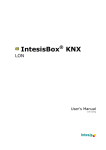
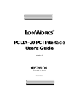
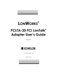
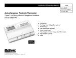
User Manual
UM 732-2
Group: Controls
Part Number: UM 732-2
Date: May 2004
Supersedes: UM 732-1
ServiceTools™ for MicroTech II™ Version 2.0 Applied Terminal
Systems User Manual
© 2004 McQuay International
Contents
General Information .............................................................................................................. 4
Purpose .................................................................................................................................................. 4
Description ............................................................................................................................................ 4
Hardware/Software Requirements......................................................................................................... 5
Component Data.................................................................................................................................... 5
Connecting ServiceTools for ATS ....................................................................................... 6
To Use ServiceTools for ATS ............................................................................................................... 6
Opening the ServiceTools for ATS Program ...................................................................... 9
How to Open an N2Open/Standalone Screen...................................................................................... 10
How to Open a BACnet Screen........................................................................................................... 13
How to Open a LONWORKS Screen..................................................................................................... 17
ServiceTools for ATS PlugIn .............................................................................................. 21
Downloads ........................................................................................................................... 24
Application Downloads ....................................................................................................................... 24
Local User Interface (LUI) Downloads............................................................................................... 27
Saving and Downloading Custom Configurations .............................................................................. 28
Loading Updated Applications to Your Computer.............................................................................. 29
Changing Network Parameters .......................................................................................... 30
Changing BACnet Network Parameters.............................................................................................. 30
Changing LONWORKS Network Parameters ......................................................................................... 32
Renaming the Device .......................................................................................................................... 32
2
UM 732-2
Limited Warranty
Consult your local McQuay Representative for warranty details. Refer to Form 933-43285Y. To find
your local McQuay Representative, go to www.mcquay.com.
Notice
©
2004 McQuay International, Minneapolis MN. All rights reserved throughout the world.
McQuay International reserves the right to change any information contained herein without prior
notice.
(™) (®) The following are trademarks or registered trademarks of their respective companies:
LonTalk and LONWORKS from Echelon Corporation, BACnet from ASHRAE, and Protocol
Selectability, MicroTech II, and AAF-HermanNelson from McQuay International.
License Agreement
ServiceTools for MicroTech II™ Applied Terminal Systems Unit Controllers software is the
exclusive property of McQuay International. It is restricted for use on a single computer. The
Licensing Agreement must be accepted by the user when installing the software. ServiceTools™ for
Applied Terminal Systems is provided as a tool for servicing McQuay MicroTech II™ Applied
Terminal Systems Unit Controllers exclusively and should never be used to access or alter
application software of other McQuay or non-McQuay products.
The program contents are confidential and may not be copied, de-compiled, disclosed, or used for
other purposes without the express written consent of McQuay International.
ServiceTools software is protected by federal copyright law. All unauthorized reproduction is
prohibited.
3
UM 732-2
General Information
Purpose
ServiceTools™ for MicroTech II™ Applied Terminal Systems (ServiceTools for ATS) provides a
method for accessing and modifying data and parameters on AAF®-HermanNelson® Applied
Terminal Systems equipped with the revolutionary new MicroTech II Unit Controllers the with the
Protocol Selectability™ feature. It allows qualified servicing and engineering personnel an easy
access to unit operating parameters and setup through their laptop PCs. In addition, it permits
downloading of applications and other data to MicroTech II ATS Unit Controllers.
The two-plug feature of the service cable provides access to MicroTech II ATS Unit Controllers
either through a network-communication module or by plugging it directly into the unit controller
board. For more information on the service cable, you can find the document (IM 762 “MicroTech
II™ ServiceTools™ Applied Terminal Systems Service Cable for AAF®HermanNelson® ATS
Controllers) at www.mcquay.com.
Note:
ServiceTools for ATS Service Cables may not be used to access LONWORKS®
Communication Modules. See the instruction under the section titled “To Use ServiceTools
for ATS” on page 6.
Description
The ServiceTools for ATS package includes the ServiceTools software and the Applied Terminal
Systems Service Cable. The software and special cable assembly provide a connection between your
computer and MicroTech II ATS unit controllers.
ServiceTools for ATS provides the following benefits:
♦
Easy configuration of stand-alone units
♦
Easy downloading of software
♦
Diagnostic tools
Note:
ServiceTools for ATS is designed for use on MicroTech II Applied Terminal System Unit
Controllers only. It may not be used on other McQuay product types, on other brands of
equipment, or on earlier AAF-HermanNelson product types.
The Applied Terminal Systems Service Cable connects MicroTech II ATS Unit Controllers that are
equipped with BACnet® communication modules, N2Open communication modules, or are standalone units, to the 9-pin serial port on your computer. The Applied Terminal Systems Service Cable
comes equipped with a 9-pin serial-cable PC connector and two 8’ long interface cables. One 8’ cable
has a three-terminal receptacle that fits into the network-connector plug on BACnet and N2 Open
communication modules. The other 8’ cable, which is designed to connect to Unit Controller boards
with no communication module installed (stand-alone), has a 12-pin connector that plugs onto the
JP1 pins on the board.
Figure 1. MicroTech II™ ServiceTools™ Applied Terminal Systems Service Cable for AAF®HermanNelson® ATS Controllers.
4
UM 732-2
Hardware/Software Requirements
Hardware Requirements
• Pentium class processor
• 128-MB RAM
• 1-GB hard-drive recommended (100-MB free disk space minimum)
• Color display with 2-MB video memory and 1024 X 768 resolution (800 X 600 resolution
minimum)
• 4X CD-ROM drive
• 9-pin serial connector (USB port with USP-to-serial-port adapter not supported)
Software Requirements
• Windows 98®
• Windows 2000® Service Pack 2
• Windows XP® Service Pack 1
• Windows NT® Service Pack 6
Note:
Although ServiceTools for ATS may operate on other Windows® platforms, McQuay
International supports only those listed above.
Component Data
The Applied Terminal Systems Service Cable connects to your PC via its 9-pin serial port. It receives
power from the computer through the serial cable. It connects to the ATS Unit Controller board by
these methods:
1.
For stand-alone units (no network communication modules installed) there is a 12-pin receptacle
located at the end of the cable labeled Stand Alone, that connects directly onto the 12-pin prong
terminals (JP1) on the unit controller board (see Figure 2).
2.
For N2 Open systems, ServiceTools for ATS has a 3-pin receptacle located at the end of the
cable labeled RS485, that connects to the prong 3-pin plug (SG1) on the communication module
(see Figure 3).
3.
For BACnet systems, ServiceTools for ATS has a 3-pin receptacle located at the end of the cable
labeled RS485, that connects to the prong 4-pin TB2 plug on the BACnet module (see Figure 4
for proper orientation).
Note:
5
ServiceTools for ATS can be connected to multiple networked units by removing the 3-pin
ServiceTools plug from the RS485 cable and connecting the wiring directly to the network
connector of one of the networked unit controllers.
UM 732-2
Connecting ServiceTools for ATS
!
WARNING
Electric shock hazard. Can cause personal injury or equipment damage.
This equipment must be properly grounded. Connections and service to the MicroTech II
control panel must be performed by personnel who are knowledgeable in operation of the
equipment being controlled
!
CAUTION
Static sensitive components. Can cause equipment damage.
Discharge all static electrical charge by touching the bare metal inside the control panel before
performing any service work. Never unplug cables, circuit board terminal blocks, or power
plugs while power is applied to the panel.
To Use ServiceTools for ATS
6
1.
Access the ATS Unit Controller panel and do the following:
•
On stand-alone (non-networked) systems, use the ServiceTools for ATS stand-alone (12-pin)
connector cable which is labeled Stand Alone to connect to the JP1 terminal on the unit
controller (see Figure 2).
•
On N2 Open systems, insert the 3-prong receptacle ServiceTools for ATS plug at the end of the
cable (labeled RS485) into the 3-prong (SG1) plug on the communication module, or remove the
3-prong receptacle and direct-wire the ServiceTools for ATS RS485 cable to the connector for a
network connection (see Figure 3).
•
On BACnet systems, carefully insert the three-prong ServiceTools for ATS plug at the end of the
cable labeled RS485 into the 4-prong plug (TB2) using the inner pins (RT+, RT-, and COM) on
the BACnet communication module (see Figure 4). To connect to multiple networked units,
remove the 3-prong receptacle from the RS485 cable and direct-wire the RS485 cable to the
network.
•
On LONWORKS systems where there is no access to an Echelon PCC-10 or SLTA-10 LonTalk
network adapter, turn off the power to the unit controller, remove the network communication
module from the Unit Controller board, unplug the network plug, and set the board aside in a
safe place. Then use the ServiceTools for ATS stand-alone (12-pin) connector to connect to the
unit controller’s JP1 terminal (see Figure 2) and reapply power.
•
On LONWORKS systems where there is no access to either an Echelon PCC-10 or SLTA-10
network adapter, insert the 2-wire Echelon approved network wire from the network adapter into
the A and B terminals (terminal TB1) on the unit controller’s plug for the LONWORKS
communication module. This connection will allow for direct connections to a single unit or a
global connection of multiple units (see Figure 3).
2.
3.
Connect the ServiceTools 9-pin cable labeled “Serial” to your computer’s 9-pin serial port.
Find and open the ServiceTools for ATS program. From your computer’s Start menu select:
Programs/McQuay ServiceTools/MicroTech II ATS (see Figure 5).
UM 732-2
Figure 2. Proper orientation of 12-pin Applied Terminal Systems Service Cable plug when
connecting it to the Unit Controller board
Figure 3. Typical ServiceTools for ATS connection to a single LONWORKS or N2 Open
Module or network connection (shown below)
7
UM 732-2
Figure 4. Proper orientation of the 3-pin ServiceTools for ATS network plug when inserting it
in the 4-pin TB2 plug on a BACnet communication module
Figure 5. How to locate the ServiceTools for ATS program on your computer
8
UM 732-2
Opening the ServiceTools for ATS Program
When you select the ServiceTools for ATS program, the box shown in Figure 6 will open. It offers
the following choices of connection types:
1.
LON
2.
BACnet
3.
N2Open/Standalone
Figure 6. Select the proper network type
Select the appropriate network type and click on Next.
After the program opens, you will see the screen that is displayed in Figure 7. This is the same screen
regardless of the protocol or the plug type (3-pin or 12-pin); the only difference is the program
identification in the top left-hand side (title bar) of the window.
Figure 7. Initial ServiceTools for ATS screen
COM1 is selected as the default communication port in the pull-down box on the top left-hand
corner of this screen. This is usually the only choice available on laptop computers. However, you
may also choose COM2 if that is an option and if the service cable is connected to the COM2 port.
Options vary depending on the connector or protocol type selected. Refer to the appropriate heading
below depending on your connector or protocol type.
9
UM 732-2
How to Open an N2Open/Standalone Screen
At the top of the page, click on the Network Interface menu. There are two options: Open and
Setting Port. The default for the Setting Port option is as shown below (see Figure 8). The default
Baud Rate is 9600.
Figure 8. Communication Settings for N2 Open
Next, select Open (under the Network Interface menu, see Figure 7). In the Network View column
the network interface type (N2Open) appears. Click on the network interface identification to enable
the Network menu (see Figure 9).
Figure 9. Finding the Unit Controller
Now follow these steps:
1. Click on the Network menu.
2. Select Find. This opens a box that offers the following options:
! AutoScan
!
By Address
!
Stop
Both of the available choices (AutoScan and By Address) provide methods for locating the
particular MicroTech II Unit Controller board(s) that you wish to connect to via ServiceTools for
ATS. If you chose the AutoScan option, a box similar to the one shown in Figure 10 will open.
10
UM 732-2
Figure 10. The Net Scanning Box
Choose the range that includes the device communication module address(s) as determined
by all the SW1 settings that you are looking for and select OK.
Select By Address to open a box similar to the one shown in Figure 11.
Figure 11. The Identify Device box
3.
Select the proper Device Address (as set by the 8-position address switch (SW1) on the
communication module) and click OK.
Once the desired unit controller or controllers are found, at least one device now displays in the
Network View box. Select a device to enable the Device menu (see Figure 12).
Note:
It may take a few moments to establish board communications. A green or red stoplight on
the task bar indicates whether to wait or to proceed.
Figure 12. Device selected
4.
11
Once the green stoplight appears, the following options shown in Figure 13 will display:
UM 732-2
•
Explore NVs and CPs
•
Remove From Network View
•
Add to Display View
•
Remove From Display View
•
Parameters
•
Data
•
Launch Plugin
•
Download Application
Figure 13. Options available under the Device menu
•
•
•
•
•
•
12
Explore NVs and CPs allows access to the individual data points. Contact McQuay Technical
Support for more information.
Remove from Network View limits the number of devices displayed in the Network View or
Display View windows.
Add to Display allows you to add several points of information to the Display View portion of
the screen.
Data screen offers no writable options.
Launch PlugIn opens the Plugin window, which will be covered in the ServiceTools for ATS
Plugin section.
Download Application is described in the Downloads section.
UM 732-2
How to Open a BACnet Screen
At the top of the page, click on the Network Interface menu. There are two options: Open and
Setting Port. The default setting for the Setting Port option is shown below (see Figure 14). The
default Baud Rate is 19200. If the network is set to another baud rate (e.g. 9600 or 38400), you must
first select the proper rate to communicate with the device via ServiceTools for ATS.
Figure 14. Network Interface Settings box
In the Network Interface Settings box, the options for This address and Max Master are both
factory-set to 33. The number in the This address box shows the unique address of ServiceTools for
ATS on the network, so its number (33 here) should never be set to be the same as any other BACnet
MS/TP device on the network. ServiceTools for ATS must be assigned a unique address when other
network addresses are used.
Max Master (also factory-set at the default of 33) must be set to an address that is equal to or higher
than the number typed in the This address box (up to the maximum MAC address of 126).
Next, select Open (under the Network Interface menu). In the lower left corner of the Network
View window, a green indicator followed by the statement MS/TP Ring Established should appear. If
not, verify proper Baud rate check for a solid connection to the communication module. Click on the
network interface identification and the Network menu will be enabled (see Figure 15).
13
UM 732-2
Figure 15. Addressing the Unit Controller Board
Now follow these steps:
1. Select the network (BACnetwork) then click on the Network menu (see Figure 16).
Figure 16. Select BACnetwork then select Network
2.
Select Find. This opens a box that offers the following options:
! AutoScan
!
By Address
!
Stop
Both of the available choices (AutoScan and By Address) provide methods for locating the
particular MicroTech II Unit Controller board(s) that you wish to connect via ServiceTools for
ATS.
• AutoScan opens a box similar to the one shown below in Figure 17.
Figure 17. The AutoScan Box
14
UM 732-2
Choose the range that includes the device MAC address(es) you are looking for and select OK.
•
By Address opens a box similar to the one shown below in Figure 18.
Figure 18. The Devices Identification Box
Select the proper Device Address (as set by the 8-position MAC address switch on the
communication module) and click OK.
3.
The device is now displayed in the Network View box. Selecting the device enables the Device
menu (see Figure 19).
Figure 19: Device Selected
Note:
It may take a few moments to establish board communications. A green or red stoplight on
the task bar indicates whether to wait or to proceed.
The options shown in Figure 20 now display the following:
• Explore NVs and CPs
• Remove From Network View
• Add to Display View
• Remove From Display View
• Parameters
• Data
• Launch Plugin
• Download Application
15
UM 732-2
Figure 20. Options available under the Device menu
•
•
•
•
Explore NVs and CPs allow access to the individual data points. Contact McQuay Technical
Support for more information.
Remove from Network View limits the number of devices displayed in the Network View or
Display View windows.
Add to Display View allows you to add several points of information to the Display View
portion of the screen.
Data provides the following screen options (see Figure 21).
Figure 21. BACnet Device Data screens
The only writable options here are the Device Object ID (Instance), the Device Name, and Max
Master (1-127). Changes to these settings will be covered under the section Changing BACnet
Network Parameters.
Note:
•
•
16
If the identification for the Application ID (under Value in the Single Item View box)
appear in RED LETTERS, this is an indication that the application loaded in the
communication module does not match the application loaded in the unit controller and
will require an application download through the network input.
Launch PlugIn opens the Plugin window, which will be covered in the SeviceTools for ATS
Plugin section.
Download Application is described in the Downloads section.
UM 732-2
How to Open a LONWORKS Screen
When an ATS Unit Controller is equipped with a LONWORKS communication module, there are two
ways of connecting to a PC to run ServiceTools for ATS.
1. Method 1: remove the communication module and connect directly to the Unit Controller board
via the stand-alone cable and 12-pin plug. If you select this method, go back to the heading
“How to Open an N2 Open/Standalone Screen”
2. Method 2: purchase a PCC-10 or SLTA-10 LonTalk network adapter from Echelon (not
supplied with ServiceTools for ATS). The PCC-10 LonTalk network adapter plugs into the
network-card slot on your laptop computer. The cable must be connected to the network plug on
the MicroTech II LONWORKS communication module. An SLTA-10 LonTalk adapter has a 9-pin
serial cable to connect to the 9-pin serial port in your computer.
After the program opens, the screen shown in Figure 22 appears. SLTALON1 or PCCLON1 is
selected by default in the pull-down box on the top left-hand corner of the screen. Change the default
to correspond with the appropriate LonTalk network adapter. Select PCCLON1 if you are using a
PCC-10 network adapter. Select SLTALON1 if you are using an SLTA-10. An SLTA-10 may
require the use the Link Manager program.
Note:
It may take a few moments to establish board communications. A green or red stoplight on
the task bar indicates whether to wait or to proceed.
Figure 22. Selecting the proper communication module
At the top of the page, click on the Network Interface menu and select Open (see Figure 23).
17
UM 732-2
Figure 23. Selecting Open from the Network Interface menu
This step brings up the network interface identification under the Network View box, and the
Network menu is enabled (see Figure 24).
Figure 24. Selecting the network
Under the Network menu, select Find. The following options are available for locating the unit
controller(s):
• AutoScan
• By Neuron ID
• By Service Pin
• Stop
•
18
AutoScan locates all the units that are on the same domain. To use this option, open the Settings
option and set the domain number (55 is the system default) and then select AutoScan (see
Figure 25).
UM 732-2
Figure 25. Change the domain number from 00 to the correct address (55 is the network
default)
•
Neuron ID is used to locate the unit if you know the communication module’s Neuron ID.
•
By Service Pin is used to locate the unit. The unit displays on the screen when By Service Pin is
selected and the service pin on the module is pushed in. Several service pins can be pushed in a
network situation to address and choose from several different units.
Once the unit controller(s) is (are) located, the board Neuron ID(s) is (are) then shown
(OOA234234800 for this particular unit controller). Select this identifier to activate the Device menu
at the top of the page (see Figure 26).
Figure 26. Options available under Device when the device is selected
19
UM 732-2
The Device menu allows access to the following options:
• Explore NVs and CPs
•
Remove from Network View
•
Add to Display View
•
Remove from Display View
•
Parameters
•
Data
•
Launch Plugin
•
Download Application
•
Rename
•
Reset
•
Change Status to
•
Explore NVs and CPs allow access to the individual data points. Contact McQuay Technical
Support for more information.
•
Remove from Network View limits the number of devices displayed in the Network View or
Display View windows.
•
Add to Display View/Remove from Display View allows you to add (or remove) several points
of information to the Display View portion of the screen.
•
Parameters offers a choice of advanced features such as Download or Save as.
•
Data requires resetting the service pin. Doing this activates the LONWORKS Device Data screen
(see Figure 27) that displays information about the communication module.
Figure 27. LONWORKS Device Data box
•
Launch PlugIn opens the Plugin window. Refer to the SeviceTools for ATS Plugin section for
more information.
•
Download Application is discussed in the Downloads section.
Note:
•
•
•
20
If the identification for the Application ID (under Value in the Single Item View box)
appear in RED LETTERS, this is an indication that the application loaded in the
communication module does not match the application loaded in the unit controller. This
requires an application download through the network input.
Rename opens a box that allows you to rename the device.
Reset virtually cycles the power to the Unit Controller board.
Change Status to offers a choice of advanced LONWORKS features such as: Clear status, On
Line, Soft Offline, Hard Offline, Configured, and Unconfigured.
UM 732-2
ServiceTools for ATS PlugIn
Figure 28. Status Plug-in Screen
Selecting Launch Plugin brings up the Status window, which may look similar to the one shown
above, depending on the software application displayed. The unit configuration (application type) is
shown in the yellow block on the top left-hand side of the page. This unit is configured as an Air
Source Heat Pump with Electric Heat. The diagram also shows the Unit Status, the Effective Space
Setpoints, the Faults, and other current operating conditions.
Figure 29. General Plug-in View
21
UM 732-2
The General tab displays a window similar to the one shown in Figure 29. The General tab gives
basic operating conditions and setpoints of the unit. Only options with a white background can be
changed by double-clicking on the reading. For example, double-clicking on the text displayed in the
Heat Cool Mode (defaulted to Invalid in Figure 29) opens the dialog box (see Figure 30). Click the
pull-down arrow to the right of the Invalid value to view the options that can be written to the
nviHeatCool network variable. Select the appropriate value and then select OK. The new value now
displays in both of the Heat Cool Mode fields (nviHeatCool and nvoHeatCool).
Figure 30. Edit Value box
Note:
Writing to network variables with the ServiceTools for ATS changes the values being
monitored and controlled by the BAS (building automation system) if one is present.
Changes made to local setpoints must be communicated to the system administrator
because such instructions might conflict with or override network communication or input
instructions.
Change other settings by clicking on the drop-down arrow located to the right of the (see Figure 31)
to display the available values. Choose the correct value and then the Write button to execute the
change. Verify that the write was stored by selecting the Refresh button.
Figure 31. Changing values in a Status/Configuration box
Some values are changed by highlighting them and entering a new value (see Figure 32). In this
example, select Write to complete the change.
Figure 32. Changing values by highlighting a number
22
UM 732-2
Figure 33. Temp/Setpts Window
Note:
The Temp Setpts (Temperature Setpoints) window shows all the current temperature
setpoints in degrees C. There is no provision for the settings to display in degrees F.
Note:
Exercise caution when writing to or modifying displayed settings. If the setting you change
is an input (not a configurable setting), the corresponding output overrides the locallywired input. For example, writing a value (such as 23C) to Space Temp in the Space
Temperature block overrides the space temperature sensor. The unit now recognizes this
value as the effective space temperature for control rather than the local hard-wired space
temperature sensor.
The remainder of the ServiceTools for ATS Plugin windows use the same format as illustrated in
Figure 33. The Master/Slave window shows the operating conditions when one unit is set up to
control the operation of another unit. The BI/BO Status window displays the status of unit binary
inputs and outputs.
23
UM 732-2
Downloads
Note:
Be aware that download commands consume bandwidth and should be avoided when other
supervisory controllers are active on the network.
Perform a power cycle after downloading an application so all memory locations are
properly cleared and/or setup.
Application Downloads
An Application Download must be performed whenever:
•
A communication module or unit controller board has been replaced or field installed and both
applications must be matched.
•
An updated application has been provided by McQuay International.
•
Custom application software has been provided by McQuay International.
The method for performing an Application Download depends on the network type (N2
Open/Standalone, BACnet, or LONWORKS). The download method for each network type is discussed
in the following sections.
Note:
BACnet or LONWORKS modules require that the application resident in the unit controller
matches the application in the communication module. When the applications do not
match, the identification for the Application ID (under Value in the Single Item View
box) appears in RED LETTERS (see Figure 34). This indicates that an application
download through the network input is required.
Figure 34. Red Application ID indicates that the applications loaded in the communication
module do not match the application loaded in the unit controller
24
UM 732-2
Application downloads (when used) must be performed through the communication modules so the
application in the module matches the application in the unit-controller board. When a
communication module is installed or replaced in the field, a download must be performed to verify
that the applications present in both the communication module and unit controller match.
Mismatched applications will cause the unit to stop communicating with the network.
Selecting Download Applications in any operating platform opens the window shown in
Figure 35, where each application type is listed. Application downloads can be found under
C:\Program Files\ McQuay ServiceTools\MicroTech II ATS\Applications. For more information,
refer to the Protocol Information document (ED15065) installed on your computer in the MicroTech
II ATS file under Help.
Figure 35. Applications available for download
Select the proper application download, select the file, and click on OK. During the download, a
series of progress bars appears similar to the one shown in Figure 36.
Figure 36. Download progress bars shown during the application download process
When the download is complete, and if the application in the communication module is the same as
that in the unit controller, the Application ID appears in black letters, as shown in Figure 37.
25
UM 732-2
Figure 37. Application ID is in black letters when the applications in the communication
module matches that loaded in the unit controller.
26
UM 732-2
Local User Interface (LUI) Downloads
A second download is required to match the LUI (keypad) display to the application after the initial
download. A new LUI download is required with each new application.
The LUI download is found on the PlugIn page under the Action menu. Select Display then
Download (see Figure 38).
Figure 38. Location of the LUI display configuration in the BACnet window
The LUI display configuration files are found under C:\Program Files\ McQuay
ServiceTools\MicroTech II ATS\Applications (see Figure 39). Double-click on the proper software
model, select the file (see Figure 40), then select Open and proceed with the brief download.
27
UM 732-2
Figure 39. LUI configuration options
Figure 40. Select the LUI configuration file then click on Open
Saving and Downloading Custom Configurations
To enter setup parameters and save them for future use or to reload the same data to several units,
perform the following: enter all changes in the PlugIn window, select Action, then Parameters, and
then Save As (see Figure 41). A window opens similar to Figures 39 and 40. Save the file for future
use.
Figure 41. To save or download unique setup parameters, select the Action drop-down
arrow, then Parameters, and either Save as or Download
28
UM 732-2
To download this special setup information, select the Action menu, then Parameters, and
Download. A window opens similar to those shown in Figures 39 and 40. Locate the setup file and
click Download. This automatically enters the previously saved unit controller data.
Loading Updated Applications to Your Computer
When McQuay International provides new or special applications, use the software tool
AppIndexMaker to load the new application(s) to your computer. To do this, first open Windows
Explorer and locate the tool under C:\Program Files\McQuay ServiceTools\MicroTech II
ATS\Applications. Paste the new application(s) in that folder, then move the old application (the one
that is being replaced) to the C:\Program Files\McQuay ServiceTools\MicroTech II ATS\Archived
Applications. After the old application is moved, open AppIndexMaker located in the Applications
folder (see Figure 42). There are two files named AppIndexMaker. Select the one that is displayed as
an application.
Figure 42. Locating AppIndexMaker in Windows Explorer
Figure 43 shows the AppIndexMaker window. Click on the button labeled Update file Index to
update the application files.
Figure 43. The AppIndexMaker window
29
UM 732-2
Changing Network Parameters
Settable network options are only available in LONWORKS and BACnet.
Changing BACnet Network Parameters
BACnet MS/TP network parameters are set at the factory with the following defaults:
• Device Object ID (Instance) – Last four digits of the unit serial number.
• Device Name (Device Object) – MTII UVUC #### (where #### represents the last 4 digits of
the unit serial number).
• Max Master (1-127) – 127.
Figure 44.BACnet MS/TP Device Data (Network) setup box
Changes to any of these network settings may be made in this (BACnet Info) window. More network
options are found in the PlugIn screen on the General page under the BACnet Status/Configuration
heading. The additional network parameter BACnet Baud Rate is also found here.
Figure 45. Network settings on the Plugin General page
30
UM 732-2
It may be necessary to change network parameters because of conflicting addresses, in order to
improve network operation, or to meet the requirements of the network administrator. Follow the
guidelines listed below when modifying network parameters.
Device Object Identifier
This must be a unique number on the network. For example, set the Device Object Identifier to 1 if
no other device on the network uses the Device Object ID (Instance) of 1.
Dev Obj Name
This name (which can use letters, numbers, spaces, or characters) must always be unique among all
other devices on the network. This name is also case sensitive, so it must be addressed using the
selected case size, spaces, and digits. For example, set the Dev Obj Name to read Unit 1 if no other
device on the network uses the Device Name, Unit 1.
BACnet Baud Rate
The number selected from the BACnet Baud Rate drop-down menu must correspond to the baud
rate that has been established for the network by the network administrator. All devices must be set to
the same baud rate to communicate. On a new network, the highest baud rate (19200) provides the
fastest communications. However, the slowest baud rate (9600) may be selected when required.
Max Master (1-127)
To speed communications, this number should be set no higher than the highest MAC Address
(setting on the communication card 8-position switch) in the network. For example, if there are eight
Unit Ventilator Unit Controllers on the network and their unique MAC addresses are set from 1 to 8
and the ServiceTools for ATS MAC address is set to 9 (see Figure 14), the number in this box should
be set to 9. This results in the network only polling these 9 devices.
BACnet Network Address
If the network number set by the system administrator does not match the default BACnet Network
Address, change the BACnet Network Address to the number established by the system
administrator. All devices on a network segment must have the same network address to
communicate.
Saving the Changes
After the parameters above have been changed, select Write to burn them into the chip memory.
31
UM 732-2
Changing LONWORKS Network Parameters
Two LONWORKS network parameters, Receive Heart Beat and Send Heart Beat intervals, can be
changed. Refer to Figure 46 under LON Status/Configure to view (but not change) the
communication card’s Neuron ID.
Figure 46. LONWORKS network parameters that can be changed
Receive Heart Beat
This configuration property is used to control the maximum amount of time that expires from the last
network-variable-input update before the controller starts to use its default or hard-wired values.
Send Heart Beat
This configurable property sets the maximum period of time between updates of certain networkvariable outputs.
Renaming the Device
If the system administrator requests that the devices be renamed prior to network integration, follow
the following steps:
Select the Device menu then select Rename (see Figure 47) from the ServiceTools for ATS initial
screen (not the PlugIn).
32
UM 732-2
Figure 47. How to rename the device
1.
The Device Rename box opens (see Figure 48). Change the device name.
Note:
The new device name must be limited to 6 characters.
Figure 48. Box for renaming the device
2.
Assigning a new device name changes the designation in the Network View box from the
Neuron ID number to the new device name.
Figure 49. The new device name
33
UM 732-2
This document contains the most current product information as of this printing. For the
most up-to-date product information, please go to www.mcquay.com.
(800) 432-1342, www.mcquay.com