1
Intelligent Discovery,
Configuration and
Composition of Devices
in a
Distributed System
Nicole Kaiyan
Thesis submitted for the degree of
Doctor of Philosophy
in the
School of Computer Science
Faculty of Engineering, Computer and Mathematical Sciences
The University of Adelaide
Adelaide SA 5005
AUSTRALIA
2014
ii
Abstract
Establishing access to the functionality of input/output devices across a distributed system
presents significant challenges worth investigating. To accomplish this requires locating
devices and understanding their identity so that requests for them can be satisfied. Current
systems require the domain of requestable devices be resolved beforehand and that they be
identified as discrete items. Additionally, configuring devices only happens if an operating
system has access to suitable drivers and composition is conducted by middleware
applications, without any system service awareness. These approaches restrict device use
in a distributed context and fail to provide a satisfactory solution.
This research has the goal of accomplishing access to devices in a distributed system
without such constraints. We present an approach where devices are described by a
language based upon a rich taxonomy of form and function. Requests for devices are
formulated using the same language and a matching process is employed to satisfy requests.
The devices capable of being matched may be rich in functionality, complex, consist of
sub-units, and include those yet to be developed. A taxonomy capturing the scope of form
and function populates the description space with terms relevant to devices.
The
description space is structured hierarchically to manage complexity. A contribution is also
made to improving the design and integration of operating systems components, in
particular, those services responsible for managing devices, from configuration through to
composition, and accomplishing such across a distributed system.
In this context,
configuration serves as a local system response to device connections, ensuring they
become operational then advertising their availability remotely. Distributed composition
services receive these notifications, adding device descriptions to a database for use when
matching requests.
We have adopted the language Prolog to describe devices and for implementing a
distributed system. It supports a database of device descriptions in the form of assertions
and provides powerful support for matching via an inference engine. The inference engine
systematically examines a potentially large and complex search space for an acceptable
extent of correspondence. Requests can be expressed minimally as those elements of a
device relevant to matching. A consequence of this style of matching is the ability to allow
requesters partial access to device functionality as a result of incomplete satisfaction.
Through awareness of the device domain, the composition process handles allocation of
control and access arbitration. A demonstration of structural matching is provided through
a fully worked example.
We set out to build a distributed system with sufficient capability to investigate
structural matching between requests for functionality and device identities. Furthermore,
to accomplish this dynamically when devices connect and permit access to their
functionality as the outcome of matching requests. The resultant schema presents a
comprehensive solution by combining a structured language, expressive enough to describe
current devices and future possibilities, with a tailored inference engine, designed to
compose an entire distributed system.
iii
iv
Acknowledgements
A research program spanning more than a decade would not have managed to sculpture a
significant contribution to knowledge without the collective support and contributions from
key people in my life.
Francis, in his role as principal advisor, receives a debt of thanks that runs deep. The
project that I came to you with required an extraordinary supervisor, to mould it into a
shape where it could fit it into a thesis. Together, we dared to dream of a better world, to
explore computer science at the edges of what was possible and to look up at the blue sky
and wonder.
Chris, as the overseeing advisor, always the sensible and wise one. I am grateful to
you for encouraging Francis and I to make something of this unique opportunity to work
together. Also, for the friendly fun evenings spent at your place discussing research, then
enjoying fine wine and food.
Peter, the enthusiastic researcher, astounding programmer and most of all a friend.
We met as both of us encountered the write up stage and, through our discussions, a
common interest in Operating Systems emerged. I look forward to the years ahead and the
chance to discuss how we might shape the discipline.
Significant friends from my journey are NV, Jonno, Richard and Thoran. I would not
have been able to figure out the important issues had each of you not been so enthusiastic
about chatting, showing insight, and encouraging me to keep gophering away. Michael B.
the mathematician, for his encouragement to stick at trying to explain the concept that I saw
outside the cave and not let wild horses drag me away from the project, no matter how hard
it becomes to make progress.
My sister, Shello, who acknowledged the sacrifices required of long term study and
the extreme financial struggle to keep the show going. You made a difference when there
was no one else I was able to turn to for support.
My mother and father, who have been there to provide support and encourage me to
keep going when I doubted my strength to continue.
Finally to my father, who such a long time ago impressed me with a grand typed
manuscript that was his PhD thesis. You inspired me to want to make my own contribution
to the world of intellectual enquiry.
v
vi
Statement of Originality
This work contains no material which has been accepted for the award of any other degree
or diploma in any university or other tertiary institution to Nicole Kaiyan and, to the best of
my knowledge and belief, contains no material previously published or written by another
person, except where due reference has been made in the text.
I give consent to this copy of my thesis, when deposited in the University Library,
being made available for loan and photocopying, subject to the provisions of the Copyright
Act 1968.
I also give permission for the digital version of my thesis to be made available on the
web, via the University’s digital research repository, the Library catalogue and also through
web search engines, unless permission has been granted by the University to restrict access
for a period of time.
____________
Nicole Kaiyan
2014
vii
viii
Contents
Abstract
Acknowledgements
Statement of Originality
List of Figures
1 Introduction
1.1
1.2
1.3
iii
v
vii
xiii
1
Home Automation
Analysing the Example
The Challenge
1
2
3
2 Issues with Distributed Systems
5
2.1 Building a Capacity to Endure
2.1.1
Model of the Process
2.2 Discovery
2.2.1 Achieving Remote Awareness
2.2.2
Shortcomings in Distributed Awareness
2.3 Configuration
2.3.1 Articulating System Dependencies
2.3.2
Impact of Dependencies
2.4 Composition
2.4.1
Describing Devices
2.4.2
Problems With Device Descriptions
2.4.3
The Distributed Match Process
2.4.4
Issues With Distributed Composition
2.5 Requirements of a System
2.5.1
Trends and Contexts
2.5.2 Arriving at the Technical Requirements
3 The Distributed System
5
5
7
7
10
13
13
24
26
26
36
36
40
41
41
42
43
3.1 Distributed Services
3.1.1
Distributed Agreement
3.1.2
Service Architecture for Composition
3.2 IO_Discovery Service
3.2.1
Tasks Performed by the IO_Discovery Service
3.2.2
Implementing the IO_Discovery Service
3.2.3
Interconnect Specification Changes
3.2.4
Requirements of Device Descriptions
3.2.5
Protocol Definitions
3.2.6
Records Maintained
3.2.7
Changes to Computer System Specifications
3.3 IO_Configuration Service
3.3.1
Tasks Performed by the IO_Configuration Service
3.3.2
Implementing the IO_Configuration Service
3.3.3
Interconnect Specification Changes
3.3.4
Requirements of Device Descriptions
3.3.5
Protocol Definitions
3.3.6
Records Maintained
3.3.7
Changes to Computer System Specifications
3.4 IO_Composition Service
3.4.1
Tasks Performed by the IO_Composition Service
3.4.2
Implementing the IO_Composition Service
ix
43
43
44
46
46
46
47
48
48
50
52
53
53
53
54
55
56
56
57
59
59
59
3.4.3
Requirements of the Match Process
3.4.4
Requirements of Device Descriptions
3.4.5
Protocol Definitions
3.4.6
Changes to Computer System Specifications
3.5 Support Services
3.5.1
IO_Resources
3.5.2
IO_Requesters
3.5.3
IO_Outlets
3.5.4
IO_Results
3.6 Event Sequencing
3.6.1
Device Connect
3.6.2
Device Disconnect
3.6.3
System Connect
3.6.4
System Disconnect
3.6.5
Requester Create
3.6.6
Requester Cancel
3.6.7
Perform Match
60
60
60
61
62
62
62
62
63
64
64
65
66
67
68
68
69
4 Taxonomy and Structural Description of Devices
73
4.1 Overcoming Named Type Restrictions
4.1.1 Assigning Types to Whole Devices
4.1.2 Assigning Types to Code Interfaces
4.1.3 Implied Device Properties
4.2 Exploring Structural Description
4.2.1
Properties to Describe Devices
4.2.2
Interaction at the User Interface
4.2.3
Physicality of Devices
4.2.4
Operational Control
4.2.5
Concurrency and Sharing Access
4.2.6
Non-Functional Aspects
4.2.7
Finer Grained Description
4.3 Building an I/O Taxonomy
4.3.1
Problems Encountered Compiling Taxonomies
4.3.2
Structurally Relating Terms
4.3.3 A Taxonomy of I/O
4.4 Device Typing
4.4.1
Structural Typing in a Distributed System
4.4.2
Describing a Device
4.4.3
Determining Equivalence
4.5 Request Formulation
4.5.1
What Makes Sense to Request
4.5.2 Adding Dimensions to Requests
4.5.3
Seeking Access and Needing to be Controlled
4.5.4
Determining Satisfaction
73
73
74
74
76
76
76
82
85
88
89
91
94
94
95
97
98
98
98
104
105
105
107
108
110
5 Composition
113
5.1 The Match Process
5.1.1
Systematically Satisfying A Request
5.1.2
Generating the Results
5.1.3
Dealing With Uncertainty
5.2 Process Enhancements
5.2.1 Arbitrating Access
5.2.2
Code Interfaces
5.2.3
Match Parameters
x
113
113
114
115
119
119
120
122
5.2.4
Quantitative Correspondence
5.2.5
Managing State
5.2.6
Match Conditions
5.3 Guiding the Search
5.3.1
Satisfying a Requester's External Access Point
5.3.2
Satisfying a Request Alternative
5.3.3
Satisfying a Request
5.3.4
Satisfying a RQGroup
5.4 Search Optimisation
5.4.1
By Structuring Requests and Devices
5.4.2
Match Process Optimisation
5.4.3
Managing Backtracking
6 Conclusion
124
125
127
130
130
132
133
136
139
139
139
140
143
6.1 Accomplishments
6.1.1
System Services
6.1.2
Taxonomy and Structural Description of Devices
6.1.3
Definition of the Process of Composition
6.2 Impact of Our Contribution
6.2.1 Achieving Context Awareness
6.2.2
Driverless Operating System
6.2.3
Matching Linked to Connection Events
6.2.4
Type System Evolution
6.2.5
Describe Devices to be Granted Access
Appendices
143
143
144
144
145
145
145
146
146
146
147
Appendix A - Audio Device Description
A.1.1 Griffin iMic v2
A.1.2 M-Audio Audiophile USB
A.1.3 Tascam US-224
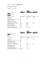
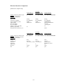
A.1.4 Device Comparison
Appendix B - A Worked Example
B.1.1 Introduction
B.1.2 The Participants
B.1.3 The Distributed System
B.1.4 The Match Process
147
147
150
153
156
158
158
158
160
162
Bibliography
183
xi
xii
List of Figures
2.1 - device and driver code dependencies upon system elements
2.10 - Universal Serial Bus (USB) Class Codes
2.14 - doing with images makes symbols model
3.2 - typical physical organisation of a system
3.3 - sphere of device responsibility example
3.4 - physical system connection topology example
3.5 - computer system organisation incorporating a processing module
3.6 - device connect
3.7 - device disconnect
3.8 - system connect
3.9 - system disconnect
3.10 - requester create
3.11 - requester cancel
3.12 - perform match (preamble)
3.13 - perform match (wrap up)
4.1 - Buxton’s taxonomy of continuous manual input devices
4.2 - Card’s Input Device Taxonomy
4.3 - ECMA User Interface Taxonomy
4.4 - Performance Characteristics for Communication Channels
4.5 - input/output model of the human senses
4.6 - PCI elaboration of engineering specifics
4.7 - Smotherman’s sequencing-based i/o taxonomy
4.8 - Miller's Systems Task Vocabulary
4.9 - category/subcategory decomposition into aspects/aspect values
4.10 - i/o taxonomy
5.1 - audio channel strip arrangement for Tascam US-224 audio device
A.1 - Griffin iMic v2 line drawing
A.3 - M-Audio Audiophile USB device front and back view
A.4 - M-Audio Audiophile device structure
A.5 - M-Tascam US-224 device front and back view
A.6 - Tascam US-224 device structure
B.1 - distributed system implementation - activity related to connection events
B.2 - distributed system implementation - activity related to the match process
xiii
14
29
33
49
51
51
57
64
65
66
67
68
69
70
70
77
78
79
80
81
82
85
86
96
97
135
147
150
152
153
155
160
161
xiv
1 Introduction
Establishing access to input/output(i/o) devices across a distributed system presents a
problem and poses significant challenges worthy of investigation. For effective use of
devices in a distributed system, they must be managed by software that enables access to
exported functionality in a reliable and consistent manner. The problem is that significant
differences exist between trying to access devices across a distributed system versus on a
computer system. For example, the range of devices available may be reduced and limited
functionality provided for distributed use.
Tackling this problem is relevant to using computers in the future. The ability to
access devices in a distributed context is becoming a significant factor in defining the
experience of computer use. We say this because the environment is already characterised
by resources being spread throughout. A plethora of computer systems and devices are
present and capable of being connected together. [Satyanarayanan, 2001]
Considering contexts of future use, the task of enabling access to devices is reliant
upon a distributed system meeting the following requirements:
(i) a flexible capacity to describe sought after devices
(ii) being made aware of devices in a context
(iii) responding to devices frequently coming and going
(iv) ensuring devices are made operational
(v) requests are matched to devices to grant access to them
An example to motivate our focus on devices within a distributed system is that provided
by building automation. The scenario of home automation provides a context which is long
lasting and involves dealing with devices to automate tasks. The actual system outlined
represents what is possible using existing technology.
1.1 Home Automation
Constructing a distributed system within a large contemporary home involves hardware and
software designed to integrate various audio/video and environmental tasks into a home
automation and entertainment system. Current commercial systems for home automation
offer a wide range of applications. [refer to Smart Home products; Savant_Systems, 2011,
Control4, 2013] The example chosen is an actual installation of a currently available
product. [Electronic_House, 2011] The implementation uses mobile phones or tablets as
touch screens to access sub-systems in the house. Configuration and control software
executes on a computer system acting as the server. There are wall mounted keypads used
for simple control operations. Sensors are used for detection, as are cameras, and spread
throughout the house are display screens and speakers.
In more detail, specialised control units (mobile phones and tablets) are used to
connect with and control displays, audiovisual components, lights, cameras, thermostats,
security systems and other home automation equipment. These units are distributed
throughout the house. The server is coupled with control units and provides a control
interface by virtue of an application. There is the option to display an interface on a
television and have navigation performed via a handheld remote control. The user interface
1
is consistent across control units and server application. They may be utilised to stream
audio/video content throughout and signal adjustments are possible per any custom setup
(e.g. close pool cover, adjust pool temperature or turn off games console). Separate from
these units are wall mounted keypads in each room, providing button controls over the
lights and buttons assigned to custom functions.
Motion detectors are used in rooms to detect occupants and adjust lights. Weather
sensors automatically switch on lights and thermostats permit temperature control.
Surveillance cameras, mounted strategically throughout the house, deliver pictures directly
to a selected display. An on-screen avatar reports visitors ringing a doorbell on the front
door. Further automation tasks include remote control of the shower according to
individual presets (e.g. temperature) or to start filling a bath. The server is utilised to store,
access and selectively distribute music, videos and television channels. It is also possible to
browse and share photos that are stored centrally. The system provides Internet access,
permitting the streaming of online videos and viewing of websites on any display screen. It
is even possible to view security cameras and interact with the control software when
remote to the house (e.g. to manage the temperature, turn lights on before returning or set
the timer on a video recorder). The system uses a photo of each room as a control template,
where lights may be switched, window shades altered, or audio/video components switched
on/off, all by touching that item in the image.
All of the equipment, be they server, mobile or audiovisual components are
constructed independently and must be logically integrated. The process of installation is
preceded by deciding which aspects of the house are to be automated. This includes the
selection and desired placement of components. Following this, the suite of control units
are programmed to facilitate sensor input and control output according to the configuration.
The mobile phones and tablets are loaded with a control application and integrated with the
servers. Then, settings are customised for the occupants. This may include user defined
control categories, environmental settings and custom interface elements.
1.2 Analysing the Example
The example was chosen to show that how a device is to be used must be determined prior
to installation. It demonstrates the extent of setup required to create a distributed system
within the context of a home. This involves tailoring server configuration to enable devices
to be controlled and linking input sensors and audiovisual feeds to particular input
channels. Then, there is the installation of custom application software on control devices
to permit them making any sense of the context. It demonstrates an architecture where the
operating system, on the server, mobile phones and tablets, has no awareness of the devices
used in the home. Finally, selection of devices and the specific control they accept is
evident in audiovisual components and simple switch operations for other equipment. In
other words, the system has a particular domain of useable devices irrespective of the effort
required to integrate them into the system.
Achieving any degree of automation within the home demonstrates the inherent
complexity to distributed systems. The programming of control units illustrates the
difficulties in making sense of other devices or even being made aware of the context of
use. This foreshadows potential problems with bringing additional control units into the
house and having them be used, or have additional devices be integrated into the suite of
audiovisual equipment (e.g. bringing another mobile phone into the house and having it be
2
able to control anything; or additional audiovisual component and ensure it may be
operated once plugged into the system). There is no treatment of how future devices are to
be handled. (e.g. future audiovisual equipment being controlled by the existing system).
1.3 The Challenge
The scenario is relevant to our work because the distributed system automating the context
of a home will need to endure, possibly for more than 30 years. During this time human
users will frequently come and go with devices. They can also be expected to arrive with
new devices. Furthermore, device input/output is a focus and remote control of them is a
feature. An objective of the system design is to automate tasks.
The actual example represents a bespoke solution and requires manual setup.
Alternate examples have adopted a similar approach, as have proposals for home
automation frameworks. [refer to the Aware Home, Android Home & C-Bus Automation
System; Abowd, Bobick et al., 2002, Clipsal_Integrated_Systems, 2005, Isaac, 2011] The
setup used extends beyond mere customisation of user interfaces, to nailing down a fixed
configuration for the entire system, ensuring control units are made aware of target devices
and the set of operations they perform. Upon closer examination, home automation is made
possible by three factors underpinning the system:
(i) the range of devices must be determined before installation,
(the capacity to describe devices is bounded)
(ii) all setup performed manually
(awareness of devices is fixed, no further devices can be brought inside & all
devices are configured at installation)
(iii) agreement has to be present at comparable levels of software on all systems
(control units are setup for access to set devices, there is no matching step)
These factors mean the system fails to meet the access requirements, stated earlier, for
ensuring future use and it will not work today unless all three have been observed.
The challenge is to devise ways of meeting these access requirements and to provide
a robust but more flexible and responsive distributed system. Our research, in the area of
operating systems and distributed systems, sets out to investigate provisioning access to
devices across a distributed system. We take up the challenge and look to building a
capacity to satisfy requests for devices not yet developed. Our goal is to build a distributed
system with the capacity to endure along with the home for the next 30 or more years.
Making progress towards improving the ability to utilise devices and lessen the
brittleness to system configuration would remove the need for a bespoke approach.
Additional control units could then be added to a context and future devices be incorporated
into the home. There is the potential to make a longer lasting contribution by attacking a
broader problem. In an environment where multiple devices are integrated into artifacts,
they are dealt with by fixing the system configuration at the time of engineering.
Enhancing our ability to deal with devices as they are discovered would enable access to
that functionality across separate engineering worlds. This would be noteworthy in
permitting distributed systems of devices to be constructed dynamically and reconfigured
into the future.
3
4
2 Issues with Distributed Systems
In this chapter, the technical requirements are established for building a distributed system.
We introduce a model of the process for gaining access to devices and use this to examine
existing work in distributed systems. The issues raised at each stage form a framework
within which a series of design requirements are derived.
2.1 Building a Capacity to Endure
Our analysis of the scenario of automating a home brought up the challenge of devising
more flexible ways of meeting device access requirements, whilst maintaining a robust
distributed system. This requires an approach that goes beyond a bespoke setup and static
configuration.
Our goal is to build a distributed system with a capacity to endure along with the
context which is long lasting, potentially spanning many decades. We intend to meet the
requirements, framing them as follows:
(i) capacity to describe and request devices, from those known to new devices and
ones not yet developed
(ii) provide device awareness
(iii) respond dynamically to devices connecting and disconnecting
(iv) ensure devices are prepared for operation
(v) match requests to devices through a process that results in granting access to them
Addressing these would contribute to future proofing the system.
2.1.1 Model of the Process
Before continuing, we define a distributed system as a cooperating set of computer systems
for which the abstraction of a single logical system is created. Its purpose is to share
resources that are physically encapsulated within computer systems and can only be
accessed from other systems by means of inter-communication. A computer system is
typified by an organisation where access to or from the processor and memory is mediated
through a device acting as a bridge. A range of further devices attach to a shared
interconnect originating from the other side of that bridge. [Stallings, 2000] Devices are
defined as a special type of resource that provides input/output to or from the physical
environment. It implements distinct functionality that is logically accessible.
To provide a context for discussing devices and requests for them, a description is
needed of the steps involved in establishing access to devices across a distributed system.
We introduce a model of this process and use the stages to structure our treatment of current
approaches to distributed systems. The key stages are drawn from those required on a
5
computer system and are the result of devices needing to be externally controlled. In broad
terms, the stages consist of:
• Discovery
involves disseminating awareness of device functionality in a distributed
system
Configuration
•
involves the preparation of a device for operation and participation in
Composition. Typically, this will involve consulting a device-based indication
of requirements, provisioning the system resources required and initialising
suitable software to perform tailored configuration of the device.
• Composition
defined as a process itself, for satisfying a request that is seeking access to
device functionality. Satisfaction involves matching a request to a pool of
device descriptions in accordance with a set of guidelines.
In the context above, device description is defined as a device based structure that indicates
the sort of functionality implemented. It is used by our work to contain structures defined
in subsequent chapters. The complement to device description is a request, which is
expressed as a logical structure using the same building blocks as a device description.
In the sections which follow, we use the three-stage model of the process to analyse
existing work and identify issues that arise within a distributed context.
6
2.2 Discovery
Significance to a distributed system
The intent behind a discovery step is to disseminate awareness of device functionality
across a distributed system. This means advising remote computer systems, where
requesters, representing software that is seeking access to a device, are located. It may also
be about advising other systems of requests requiring satisfaction. By advising we mean
disseminating notifications, which are generated by services on a computer system to
disseminate record that an event happened. This takes the form of a message sent from a
computer system to others in a distributed system. An event is defined as being generated
by services on a computer system and, typically, arises as a response to hardware signaling.
A service is a software unit that is a discrete part of an operating system. It provides an
interface that other software can access to perform tasks.
Acquiring and retaining awareness is a pre-condition for participation in composition.
Without it, reasoning on the validity of communication links is not possible. This is
because discovery is an important aspect of how connection or arrival events are handled
on a computer system and the wider distributed system. Determining which of these events
are relevant will define the sort of responsiveness built into the system.
Scope of possibilities
Providing access to resources on other computer systems is integral to providing a
distributed system. The scope for discovering these resources is reliant upon the way in
which the process of composition is driven. Also, the level of integration between
distributed software and the operating system on a computer system. A range of semantics
worth investigating consist of:
• what exactly is being discovered
• how is awareness achieved of devices or requesters on other computer systems
• how widespread is awareness within a distributed system
• what happens upon receiving a distributed notification
With a focus on discrete devices, our concern is to ascertain how awareness of connections
is achieved in a dynamic setting. This is coupled with how requests are uncovered and
acted upon.
2.2.1 Achieving Remote Awareness
A select set of distributed systems work illustrates existing approaches to discovery. Each
differs slightly in their handling of awareness. Our examination of discovery is kept
separate from composition. Where middleware is referred to, we think of this as a software
layer that provides distributed transparency, by defining protocols for communication
between corresponding layers on computer systems. It assumes a computer system has
already been configured by an operating system.
7
Publish/Subscribe
A Jini system consists of service providers, which include devices, and clients which make
use of them. [Waldo, 1998, Arnold, 1999, Sun Microsystems, 2000] The middleware is
written in Java, with clients and services constrained to have their interfaces expressed
similarly. Discovery defines the way a device service becomes part of a group (federation).
Then there is lookup which reflects the current members and acts as way of finding
services. The separate process approach is referred to as publish/subscribe.
Locating a look up service is the initial task for both services and clients. This
service is a specialised part of the Jini system. It is started independently to the process of
discovery, typically during system initialisation. It is responsible for taking device service
registrations, matching client requests and responding to these requests by listening on a
reserved port.
Devices and clients use network announcements, either multicasting messages where
a lookup service is unknown or unicasting to make contact outside of a local network but at
a known address. Jini relies upon a properly configured IP networking layer in system
software, which implies Ethernet/IEEE802 is the interconnect, and an HTTP server to
underpin execution of services.
The iRoom interactive spaces is middleware that provides event-based communication
through an intermediary which handles a variant of the publish/subscribe approach.
[Johanson, Fox et al., 2002] A management framework discovers information in the
following ways:
(vi) services periodically broadcast their presence, to a managing service, which
includes service descriptions (e.g. operations supported & their parameters)
written in a service description language.
(vii)when an appliance requests a user interface, from the managing service, it
supplies an appliance description that provides information about the appliance
(e.g. #pixels).
(viii)information about the workspace context is contained in a central datastore, this
includes physical locations and dimensions of various devices (e.g. lights &
displays), descriptive information about devices (e.g. “display1” is the “front
display”), and device relationship information (e.g. “projector2” projects onto
display “screen1”).
Multicasting
Bonjour, an Apple implementation of Zeroconf, is a service discovery protocol for locating
devices and the services that their operating systems offer on a local network.[Apple, 2005,
Cheshire and Steinberg, 2005] It is intended to work within a single broadcast domain,
typically a small IP-based network, using Ethernet/IEEE802 interconnect, without Domain
Name System (DNS) configuration. The core component for service discovery is Multicast
DNS (mDNS), implemented across a local network by computer systems storing their own
list of DNS resource records. When a mDNS client wants to know an address given a
network node's name, it sends requests to a reserved multicast address.
As the network scales, Zeroconf addresses service discovery requirements, across a
wide area, with a centralised repository for information (DNS server). This is combined
with protocols for registering device services plus updates and queries (DNS protocol), and
security mechanisms.
8
Zeroconf represents a refinement of an existing aspect to IP-networks, where service
discovery (DNS-SD) is accomplished by performing a lookup (on DNS pointer records)
using a service identifier within a domain. Responses list uniquely named instances of that
service across the local domain. These names can be browsed to select an appropriate
candidate.
Web services represent a range of specifications for a framework to support software
components exporting functionality that can be discovered and accessed over a network,
especially the Internet. Devices provide services which are defined by Devices Profile for
Web Services (DPWS), which builds on Web Services Description Language (WSDL).
[Weerawarana, Chinnici et al., 2002, Microsoft Corporation, 2006] DPWS pulls together a
core subset of the specifications, to define a minimal set of constraints for implementing
secure Web services.
Discovery is described by the Web Services Dynamic Discovery (WS-Discovery)
protocol. [Microsoft, 2005] In simple, ad-hoc deployments, involving a minimum of
network services, devices and clients respond directly to announcements from each other.
The principal approach, though, is for clients to search for device services by name, using
multicast (SOAP over UDP) on a local subnet. Devices listen for these messages and
respond with a service description back to the client when able to offer that service.
Alternatively, when a device connects to a network, it sends an announcement message
using multicast. By listening for such, clients can detect available services without the need
to probe.
Digital Living Network Alliance (DLNA) delivers media interoperability across a home
network and utilises the concept of devices, device services and control points as
requesters. [Allegro_Software, 2006, Digital_Living_Network_Alliance, 2013] It is based
on Universal Plug and Play (UPnP). [Internet_Engineering_Task_Force, 1999, Microsoft,
2000] TCP/IP, using Ethernet/IEEE802, forms the basis for all network connectivity. It
adds web standards (HTTP, HTML, XML & SOAP) to provide a framework for device
discovery, device and services description, control and presentation.
DLNA Discovery is based on the UPnP Forum Device Architecture. [UPnP, 2008b]
When a new device is added to a network, the service discovery protocol (SSDP) allows the
device to advertise its presence to the network. This message advertises its services and
location of a description. The number that must be sent varies according to the number of
distinct embedded devices and services contained therein. Due to the unreliable nature of
data communication, devices send a set of discovery messages multiple times with a delay
in between. When a control point discovers a new device, it must use the resource location
(URL) in the discovery message to retrieve a description (expressed in XML syntax and
based on a standard UPnP Device Template).
Alternatively, when a new control point is added to the network, SSDP allows it to
discover devices that are connected to the network. Thus, by listening to the standard
network address, control points and devices can be made aware of new services being
offered and respond to service requests. In each case, the response is a discovery message
that contains specifics about a device and its services. Any interested control point can
listen for device available notifications, whereas all devices must listen for search requests.
During discovery, IP multicast is used for real-time communication to associate a
sender with a group of interested receivers. This is accomplished by using specially
reserved addresses in IP networks where the source is not required to know about receivers
9
in the group. However, state information must be stored on intermediate network routers,
consisting of routing and forwarding entries for those interested. An entry is recorded for
each tree where a router has downstream receivers, with tree construction initiated by
receivers. When a sender uses multicast addressing for a message, intermediary routers
must make copies and send them to all receivers having joined a particular group.
2.2.2 Shortcomings in Distributed Awareness
Disseminating awareness is necessary for dynamic construction of a distributed system.
The examples presented, however, point to shortcomings in how existing approaches
handle discovery. A range of factors impact the flexibility and responsiveness of these
systems. These consist of the choice of interconnect used for networking, particular
software layers, the treatment of locality and an absence of distributed agreement. Each of
these are discussed in turn.
Assumed use of networking technology
Current work operates under an assumption that a specific interconnect is to be used for
networking computer systems and devices together. Others have observed near uniformity
to the use of Ethernet/IEEE802 as the interconnect for a distributed system. [Kindberg and
Fox, 2002] Additionally, this has seen widespread requirement for additional system
software to implement networking (namely TCP/IP).
A lack of diversity has resulted in the process itself being scoped by the capabilities
of the interconnect. Most particularly, discovery by using multicast on an IP subnet on top
of IEEE802. The gaining of awareness becomes framed in terms of the steps associated
with a functional description of the IEEE802 interconnect. [IEEE, 2001] This would be of
little concern if it provided all that a distributed system requires, but it does not. The
remaining points explain why alternatives are needed.
Absence of contextual awareness
An important consequence of the choice of interconnect is how locality is treated. By
locality we mean denoting where in the physical environment a device is operating or a
logical identifier on an interconnect for communication purposes. Proximity, on the other
hand, is a reference to nearness with respect to locality.
Location is handled in a similar manner across interconnects, assigning logical
identifiers to successive devices (e.g. Firewire, IEEE802, USB).
This affords a
transparency to where the device is physically and represents a straightforward way of
connecting computer systems and enabling communication between them. Consequently,
application of transparency extends to the building of middleware. [Saha and Mukherjee,
2003] A tension exists in circumstances where context awareness is required, a factor of
importance in dynamic distributed systems that prioritise physical integration.
The problem of linking the physical to the logical is exemplified by the CoolTown
project. [Kindberg and Barton, 2001] Physical proximity to tags or beacons are used across
the distributed context to facilitate discovery. A code is obtained, via a sensing mechanism,
and converted to a location-independent identifier or name for the resource (URN). This, in
turn, is resolved into a network locator (URL) for access to a webpage located on the
Internet.
10
Difficulties arise when attempting to map network location to the physical
environment (e.g. gaining access to the webpage for a printing device that is located where
in the environment?). Presently, this requires a manual configuration step prior and,
consequently, forces aspects of the distributed system to act as fixed infrastructure.
Obtaining proactive knowledge of the environment is needed for applications to make use
of context-awareness through appropriate interfaces provided by the system.
Dependence upon external network infrastructure
In choosing a style of communication where the sender of a message is unaware of who is
receiving them, existing systems have become dependent on an intermediary. The use of
multicasting is affected by network equipment, principally routers, which are nonparticipants in composition and lack awareness of higher level distributed protocols.
The essential point is that the ability for messages to be sent or received between
systems is not controllable by any of the participants or by software managing the
distributed system. This situation is the result of routers taking multicast registration from
interested listeners and handling delivery of messages to them. However, the extent of and
depth to the re-transmission of messages is configured alongside the network infrastructure
not the distributed system.
Removing this dependency upon equipment, that must be statically configured, is
necessary to improve distributed system robustness and ensure composition can happen
anywhere.
Lacking awareness of computer system events
Existing approaches are characterised by a sense of disconnection to their operation. What
is happening on each computer system is separate from the distributed system. This stems
from awareness not being provided or deemed to be an area of concern. The failure to
percolate events up, through intervening software layers, rests with the operating system
and middleware.
The events being talked about are generated on interconnects where a device
connection or disconnection registers at the hardware level, and is detected by all systems
attached to that interconnect.[e.g. Firewire; IEEE, 1995b] A lack of an equivalent
mechanism in the interconnect used by existing systems means widespread awareness of
any disconnections is problematic, be they device or other systems.
To compensate for a lack of explicit awareness, DLNA’s discovery messages (UPnPbased) include an expiration time and eventually expire on their own. The only advice
given for device disconnections is to re-multicast a message and control point departure
yields no action at all. [UPnP, 2008b] Similarly, Jini attempts to compensate for being
distributed by devices registering their services on a leased basis, which times out, meaning
it requires explicit renewal. [Sun Microsystems, 2003] An example of consistent linkage
through to process initiation is the Bluetooth interconnect, which implements hardware
level recognition of departure or arrival.
This means applications based on these
notifications can rely on them being carried up the protocol stack and discovery being
triggered. [Bluetooth SIG, 2009]
What discovery needs is linkage between low-level hardware events and the rest of
the process (configuration & composition).
This means deciding on which events
generated on a computer system are relevant to devices and determining what to do when
they happen. Then, what notifications to send to other systems and how to respond to such
when received from the wider distributed system.
11
Failure to reach distributed agreement
Despite the relative uniformity of expressing device functionality as services, and the use of
multicasting on IEEE802 interconnects, interoperability eludes existing work.
The
diversity to abstraction, which is covered in the next section, is a factor, as is a slightly
different framing of the process.
For interoperability to be a reality, there needs to be distributed agreement on what is
being discovered, be that a service, resource, device or a code interface? However, the
challenge continues to be seen as purely a practical obstacle of arriving at the same
vocabulary and syntax. [Kindberg and Fox, 2002] This fails to consider the semantics of
the process, which would lead to determining what notifications to send between
distributed system.
12
2.3 Configuration
Significance to a distributed system
A separate stage is required to prepare a device for operation and to ensure their
functionality is made accessible. Because devices require system resources to function, we
cannot assume configuration occurs without incident. Further, they lack autonomy, due to
needing external intervention to arbitrate access to them, control their operation and be
configured.
Uncovering those system relations which constrain device preparation becomes
critical in a context where they connect dynamically. It also has relevance beyond them
becoming operational. Configuration is how they are made ready to participate in
composition across a distributed system.
Scope of possibilities
Because constraints have the potential to prevent devices being configured, investigating
their impact is worthwhile. When they arise is not limited a device connecting to a system.
They emerge during development as constraints are placed on the design of devices and
driver code. The value in articulating them is to explicitly account for factors that affect the
process.
Our focus is to investigate relations between elements on a computer system. This
includes identifying the provider of resources required by a device and which system entity
is arbitrating or controlling them. At the same time, to articulate the constraints present and
the way existing systems have attempted to handle dependencies.
2.3.1 Articulating System Dependencies
Device Related System Elements
Whether permanently attached or connecting dynamically, device initialisation involves key
elements of a computer system. For our purposes, these elements consist of:
• devices
defined earlier and including interconnect bridges.
driver
code
•
is deployable software developed with the intention to configure and operate a
specific device.
• kernel code
is the section of an operating system that executes with security privileges and
is responsible for resource management of a computer system;
it comprises services providing interprocess communication, scheduling,
memory management and interrupt handling.
platform
configuration code
•
refers to software embedded in a system platform with responsibility for
performing bootstrapping;
it is tasked with establishing a viable logical configuration, enumerating
attached devices on known interconnects and, using a fixed pool of drivers, to
configure those devices required to load an operating system;
13
a system platform refers to a specification for a computer system, consisting of
a target processor and a suite of devices, intended as a guide for developing an
operating system.
• processor
- unit of general purpose code execution in a system;
implicitly includes memory.
• interconnect specification
- provides form and function underpinning for all devices that are developed to
connect to a particular interconnect;
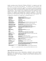
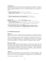
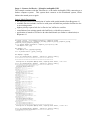
Although dependencies do exist between each of these system elements, our concern is to
narrow our treatment to those specifically related to the process of configuration. This
means examining the dependencies devices and their driver code have upon other elements
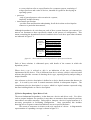
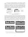
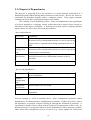
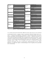
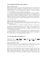
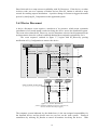
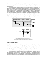
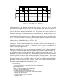
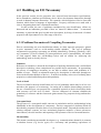
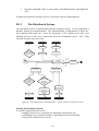
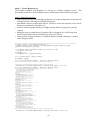
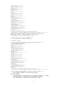
are indicated in figure 2.1.
driver code
i/o device
dependencies
upon
kernel code
platform configuration code
interconnect specification
processor
kernel code
driver code
dependencies
upon
platform configuration code
interconnect specification
processor
figure 2.1 - device and driver code dependencies upon system elements
Each of these relations is elaborated upon, with details of the context in which the
dependency arises.
Where device type is referred to, this is an indication of the sort of functionality
implemented by the device. This is different from device identity, which is a device based
structure that provides a means of denoting device type, reporting locality and providing a
unique identifier.
Also reference to device description is defined as a device based structure that denotes its
type. It is used by our work to contain structures defined in subsequent chapters. The
complement to device description is a request, which is a logical structure expressed using
the same building blocks as a device description.
[1] Device Dependency Upon Driver Code
The most fundamental dependency is that between a device and driver code. For driver
code to prepare hardware for operation, it must have an awareness that extends beyond any
interconnect accessible structures. Being able to interpret a device’s logical structure is a
necessary prerequisite to facilitating configuration.
Once operational, this includes
knowing how to sequence control and arbitrate access to specific hardware.
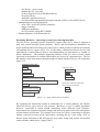
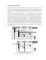
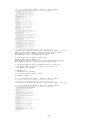
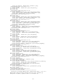
The extent of awareness is relative to the role expected of a driver. A diagrammatic
representation of expanding coverage is shown in figure 2.2.
14
specific driver code
standardised interface
driver code
interconnect
driver code
i/o device
figure 2.2 - relative driver coverage of a device
Coverage begins with access via a bridge to an interconnect, upon which the device is
attached (e.g. access to PCI interconnect configuration space on a device). It extends
through to standardised interfaces exported by a device (e.g. VGA graphics compatible
structures), to a specific device instance (e.g. specific graphics accelerator).
At a minimum, an interconnect bridge driver is aware of logical structures and access
mechanisms specific to that interconnect. This means it is able to access connected
devices. The dependency relation concerns extraction of an identification block during
configuration. An example is driver code for a PCI to Firewire bridge which can introspect
devices on the Firewire interconnect to discover their identity. [refer to Texas Instruments
TSB43AB23 based PCI adapter card; Texas Instruments, 2003]
Becoming more specific, a standardised interface driver includes interconnect
specified structures but extends comprehension to a set of interfaces and access
mechanisms for particular device hardware. The dependency is for configuration and
operation in compliance with a standard that establishes a distinct type around features
common to more than one device. The PCI to Firewire bridge cited above is Open Host
Controller Interface (OHCI) compliant and can be managed by a driver targeted at that
specification. In this case, additional features implemented by the bridge are simply not
recognised and, hence, not logically accessible. [refer to Firewire OHCI 1.1 specification;
OpenHCI, 2000, Texas Instruments, 2003]
For device specific drivers, coverage expands beyond interconnect specified
structures and any standardised interfaces, to those features implemented by a particular
device. The dependency is for tailored configuration and operation. A pertinent example is
a Matrox G400 AGP interconnect based graphics adapter, implementing a PowerMode suite
of features in addition to the Video Graphics Array (VGA) standard. A driver with full
awareness is needed for the device to exhibit any functionality beyond VGA compatibility.
[Matrox Graphics, 1999]
[2] Device Dependency Upon Interconnect Specification
An interconnect specification defines logical interfaces to facilitate reference by an
interconnect bridge driver. A device implements these structures to provide an indication of
its particular type and which system resources are required (e.g. interrupt signaling,
memory access). It also specifies the mechanisms through which logical access is to be
performed and organises the manner in which the device is to respond when this happens.
These aspects are outlined with reference to the Firewire interconnect.
15
At a basic level, an interconnect determines how a device attaches to a computer
system.
It determines the physical characteristics of that connection, from the
manifestation of the actual connector through to the particulars of electrical signaling. By
designing a device for attachment across an interconnect, it is implied that the underlying
specification has been adhered to in its entirety. The Firewire specification details a range
of connectors that can be employed. From the physical dimensions through to the
mechanical properties, it is expected that any use of them in a device is fully compliant.
Provisioning of device power, across the interconnect, is possible by virtue of cabling
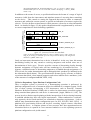
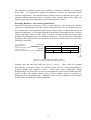
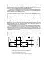
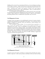
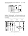
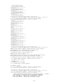
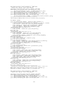
options, permitted as a result of the connector employed, as is shown in figure 2.3.
7.1mm
6
4
6.3mm
5mm
5.4mm
5
3
pins
1 - power supply
2 - ground
3, 4 - signal line A
5, 6 - signal line B
2
3 4 5 6
3.4mm
1
11mm
Firewire 400 6-pin connector
Firewire 400 4-pin connector
figure 2.3 - Firewire-400 4- or 6-pin cable connector
[IEEE, 1995b: 93, IEEE, 2000: 79]
At a different level, the specification defines the electrical signaling parameters required for
a device to connect and logically participate in communication. [IEEE, 1995b, IEEE, 2000]
The interconnect defines the manner of logical access, from simple data references, through
memory mapping, to the exchange of data packets. Firewire articulates device-based
structures in terms of a distinct address space, divided into buses, nodes and then device
memory. Access to interconnect addresses is via distinct packet-based communication,
ranging from asynchronous through isochronous to transmit data. The logical structure of
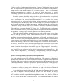
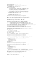
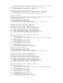
data packets delivered to or from a device are illustrated in figure 2.4. [IEEE, 1995b]
srcBusID
reserved
srcBusID
reserved
spd
destinationID
tLabel
rt
4
tCode
reserved
reserved
destinationOffsetHigh
reserved
spd
destinationID
destinationOffsetLow
tLabel
rt
rCode
6
tCode
reserved
reserved
reserved
quadletData
Asynchronous Transmit Read Request - Quadlet
Asynchronous Transmit Read Response - Quadlet
srcBusID
reserved
srcBusID
reserved
destinationID
spd
tLabel
rt
5
tCode
reserved
reserved
reserved
destinationID
destinationOffsetHigh
destinationOffsetLow
dataLength
spd
tLabel
rCode
rt
7
tCode
reserved
reserved
reserved
dataLength
reserved
reserved
data
Asynchronous Transmit Read Request - Block
Asynchronous Transmit Response - Block
figure 2.4 - range of Firewire packet formats for asynchronous data transmission
16
{destinationOffsetHigh & destinationOffsetLow refer to a device’s address space;
destinationID refers to the bus and node number identifying a device} [IEEE,
1995b: 152]
410
39h("9")
34h("4")
8 bits
8 bits
8 bits
rsvd
3 bits
8 bits
1 bit
1 bit
1 bit
1 bit
1 bit
cyc_clk_acc
max_
rec
8 bits
4 bits
gen
rsvd
33h("3")
8 bits
rsvd
31h("1")
irmc
cmc
isc
bmc
pmc
Bus Info Block
40C
408
404
In addition to the means of access, a specification dictates the format of a range of logical
structures visible from the interconnect and stipulates means of accessing those remaining
on the device. This extends to stating the approach that must be taken to enumerate
structures and, utilised in current systems, to provide an indication of resources required by
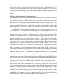
a device. Firewire defines an interconnect visible structure, referred to as a bus information
block. As detailed in figure 2.5, this guides identification and is supplemented by reference
to a more comprehensive block indicating capabilities.
link
_spd
BUS_ID
BUS_OPTIONS
3 bits
2 bits
3 bits
node_vendor_id
chip_id_hi
24 bits
8 bits
chip_id_lo
GLOBAL_UNIQUE_ID_HI
GLOBAL_UNIQUE_ID_LO
32 bits
figure 2.5 - format of Firewire bus info block
{starts at location FFFF F000 0404 in a device’s address space; node_vendor_id,
chip_id_hi & chip_lo combined represent unique EUI-64 identity code assigned to
that device} [IEEE, 2000: 170]
Lastly, an interconnect determines how a device is identified. At the very least, this means
determining locality but may extend to resolving uniqueness and include some sort of
determination of device type. Firewire provides a means of determining locality through
dynamic assignment of logical node and bus numbering for all attached devices. A
separate, centralised means of determining uniqueness is handled through assignment of a
EUI-64 code for vendor determination and to distinguish their products (as indicated in the
bus information block shown). The specification also dictates type by reference to fields in
a persistent data block, where named properties and values indicate device attributes. [refer
to the structure of configurationROM; IEEE, 1999]
[3] Device Dependency Upon Platform Configuration Code
Once a computer system is powered on, a bootstrapping operation is performed, by
platform configuration code, to enumerate all devices attached to a computer system. In the
case of those systems incorporating a PCI interconnect, such as PowerPC Common
Hardware Reference Platform (CHRP), this is realised as interconnect accessible registers
being consulted then updated as each device is enumerated. [Apple, IBM et al., 1995] The
process involves distinct steps beginning with the introspection of devices during bootstrap,
to establish whether they have any logical requirements. When conducted as a softwareonly approach, device-based structures are consulted to determine requirements. [refer to
address map determination under configuration space for PCI; PCI-SIG, 2002: 205-8] A
platform-level provisioning follows and involves recording logical resource allocations
back with the device. A complete picture of how resources have been apportioned across
all attached devices is captured in a tree structure handed over to the operating system as
platform configuration code yields control.
17
Resolving whether a system is viable depends on arriving at a conflict free allocation
of logical resources, be that apportioning regions of memory or allocating interrupt signal
lines. The requirement for logical resource provisioning acts to break device independence,
through reliance upon external software for an essential element. This is exacerbated by
platform configuration code needing to be aware of which interconnect, to ensure
provisioning appropriate driver code to even locate the device and permit minimal device
access.
In earlier systems, physically setting switches on devices themselves accomplished
resource assignment to permit access and signal events. The particular requirements varied
across interconnects but required manual determination of a conflict free system
configuration.[refer to background to developing software approaches to replace physical
switch settings; Intel and Microsoft, 1994] An early example of device-based assignment is
that of systems employing the Unibus interconnect. Although utilising the connection slot
to determine locality, it relied upon device switches to determine which memory address
region that particular device type’s registers were to be mapped. [refer to discussion of
setting addresses for memory mapping i/o; Varga, 2010] The historical trend to performing
conflict resolution in software, principally by platform configuration code, has not removed
the dependency. It simply targets resolving platform level reliability concerns.
With the gradual expansion of interconnect types and possible target devices from
which to load the operating system, a different set of issues has arisen for platform
configuration. The execution environment, prior to loading an operating system, is not
intended to incorporate functionality akin to that once an operating system kernel takes
control. Its objective is to enumerate attached devices, perform a conflict-free allocation of
system resources and configure sufficient devices to permit loading the operating system.
However, the handling of devices is far from thorough and is restricted to those for which it
has a driver. The flow on effect is to reduce operating system awareness of devices to the
contents of the tree structure, handed over by platform configuration code, which may not
contain all attached devices due to interconnect types not being recognised. Furthermore,
the operating system is unable to rely upon any firmware driver code having executed,
hence it must resort to performing its own device configuration across the entire tree. The
overall effect is duplication of responsibility, most particularly, code for loading an
operating system and a suite of drivers, each implementing limited functionality.
[4] Driver Code Dependency Upon Interconnect Specification
A consequence of a device being designed to connect via an interconnect is the need for
driver code to also be aware of the underlying specification. This comprises definitions of
logically visible structures. It extends to how access to them is expressed and a functional
description of the process of device control and communication. We mentioned earlier that
a device implementation embodies dependencies upon the interconnect. With respect to
driver code, we can characterise its dependencies as comprising a distinct code block with
interconnect awareness and another concerned with the functionality a device implements.
To illustrate the utility in drawing such a distinction, we look at two devices of identical
task functionality but interfacing to a computer system via differing connections.
A two-dimensional mouse with a left and right button demonstrates the effect upon
driver code of adopting a different connection interface. In either instance, the device
adopts a communication protocol where multiple data bytes are sent containing change in X
and Y coordinate position along with left and right button status. One, however, utilises a
RS-232-C serial and the other a USB interconnect. The former transfers data at a rate of
18
1200 bits per second and employs a system interrupt per single byte transferred. It uses
ports from i/o space to read successive bytes received from device. [USARSystems, 1997]
The USB version transfers data in the form of discrete packets, at rate of up to 1.1Mbps, to
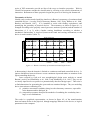
a buffer with system memory. A system interrupt is generated once multiple bytes have
been sent from the device.[STMicroelectronics, 1999, Compaq, Hewlett Packard et al.,
2000]
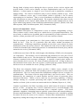
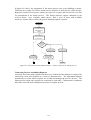
[5] Driver Code Dependency Upon Kernel Code
This dependency can be characterised statically in terms of structure definitions, as well as
dynamically, by the manner in which a driver interacts with the kernel. In particular, the
code structure of a driver is defined by the kernel. The nature of such being an executable
unit means it must comply with requirements set down by the target operating system. This
includes managing driver lifecycle within the runtime environment and provisioning system
resources required for the driver, as distinct from the device. The manner of access to the
kernel is specified, for allocation, control and arbitration of logical resources for driver and
device during operation.
Broad reliance upon a particular kernel is due to more than just the driver being a unit
of executable code. It is tailored for a particular purpose. During configuration, a driver’s
external references to the operating system are not dynamically composed, that have
already been statically resolved at development time. The inherent awareness of the
semantics and syntax of services is evidence of their tight integration into the kernel. The
extent of compliance includes adopting the kernel’s security model, in terms of memory
and input/output access, along with interrupt signaling. This extends to the execution
model, defining the extent of arbitrated access to and the dynamic picture of what driver
code looks like to the rest of the system. It encompasses how driver code references
external software, be they to elements of the kernel or other software. There is little
variance to the pattern across commercial operating systems. Some effort has been
expended to tackle the knowledge required for code development, through incorporation of
driver requirements in object-oriented code libraries, as in Apple’s I/O Kit. [Apple, 2007]
This enables key details to be implemented within a system library pertaining to interfacing
with the kernel and reduces the steps to be undertaken when developing a driver for that
particular operating system. It accomplishes hiding the complexity but in no way tackles
removal of the dependency. A clearer illustration of the extent of engineering required is
that of the Device Driver Environment (DDE) provided for the L4 operating system, to
permit drivers targeted at the Linux kernel to execute in a different context.[Helmuth, 2003]
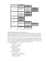
The extensive array of services is presented in figure 2.6 and must be implemented fully in
order to encapsulate the driver and create the illusion that a different kernel is present. This
provides a succinct overview of the dependency as it stands in a current operating system.
The nature of this dependency is best understood in terms of the evolving nature of
device related code. Prior to the emergence of drivers as loadable units, any i/o-related
code was an integral part of an operating system kernel. With the advent of interconnects
capable of accepting any device controller that adhered to their specification, the tight
coupling of an operating system to the hardware was broken. This led to providing
additional code, after the operating system had been developed for a target system, in order
to make sense of the new device. This is characterised by the RT-11 operating system for
the PDP-11 series computer systems. It handles particular devices connecting to Unibus
via code distinct from the kernel and separately loadable. [Digital, 1984]
19
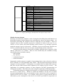
Interrupt Handling
● Request / Release Interrupt
● Initalize IRQ handling
● Get IRQ thread number
Memory Management
● kmem Allocation / Deallocation
● vmem Allocation / Deallocation
● Initalize LMM pools and initial regions
Address Conversion Linux' __va()/__pa() macro replacements
Page Allocation/Deallocation (mapping knowledge (addresses & sizes) remains in drivers)
Slab Caches (introduced for Linux USB drivers)
PCI Bus/Device Support
● Initalize PCI module
Exploration of bus/attached devices and drivers
Device setup (bus mastering, enable/disable)
Power Management related functions
PCI memory pools (consistent DMA mappings)
Configuration space access
Functions for Linux backward compatibility (drivers/pci/compatc)
Process Level Activities
● Get pointer to current task structure (this replaces the "current" macro)
● Add / Remove a caller as process level worker
● Initalize process module
● Create kernel thread
Scheduling Primitives (kernel/schedc)
Wait Queue - List Manipulation (kernel/forkc)
I/O Resource Management
● Allocate / Release I/O port / memory region
● Release any resource
● Check I/O port / memory region availability
● Remap / Unmap I/O memory from kernel address space
● Remap I/O memory into kernel address space (no cache)
Deferred Activities
● Initalize Softirq Thread(s)
Softirqs (include/linux/interrupth) (softirqs are multithreaded, not serialized BH-like activities)
Tasklets (kernel/softirqc & include/linux/interrupth) (tasklets are multithreaded analogue of BHs)
(differ from generic softirqs: one tasklet is running only on one CPU simultaneously;
differs from BHs: different tasklets may be run simultaneously on different CPUs)
Old-style Bottom Halves and Task Queues (kernel/softirqc)
Time and Timer Implementation
● Initialize Timer Thread
Linux Timer Handling (kernel/timerc)
figure 2.6 - overview of DDE/Linux2.6 environment for L4 kernel
{provides general Linux kernel interface emulation, for Linux device drivers under
L4, implemented as a set of interfaces to particular subsystems} [refer to Linux
Device Driver Environment Manual v0.5-2.4.27; Helmuth, 2003]
Despite drivers being separately deployable software units, kernel dictates contribute
additional complexity and bulk in terms of structure and the manner of communication.
These considerations are over and above device specific or even interconnect-related code.
Drivers based upon Windows Driver Model (WDM) for Microsoft’s XP/ Vista/ 7 operating
system necessitate developers being aware of support code requirements, and then to
include blocks of kernel code to enable execution. [Oney, 2003] The contingent nature of
these dependencies means they apply to only that kernel. This is despite driver code having
similar logical resource requirements irrespective of which kernel, such as requiring
memory allocation or access to a memory region. Attempts to address these issues have
resulted in tailored development environments for the preparation of drivers. These
environments endeavour to tackle complexity by defining a series of device types based
20
around those encountered on system platforms for which the operating system is targeted.
In the case of Apple’s I/O Kit, there is little support offered for device types outside those
chosen arbitrarily for inclusion with their development environment. [Apple, 2007]
Likewise, development under Microsoft’s WDM exhibits complexity due to the failure of
kernel to provision fault tolerance. This leads to drivers being expected to implement
recovery actions, such as orderly cancellation of i/o operations. [Oney, 2003] Attempts to
bridge the gap between realisation and requirements resulted in the Uniform Driver
Interface specification. [Project_UDI, 2001a, Project_UDI, 2001b] This effort sought to
encapsulate common driver functionality inside a portable environment which would
require limited interfacing for each kernel. Although promising the reuse of core
functionality for a particular driver, the engineering required results in complexity at the
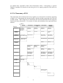
point where the environment interfaced to the kernel. This is illustrated in figure 2.7 for a
UDI-based driver for the USB interconnect.
Application Code
UDI USB interface
OpenUSBDI
Logical Device Drivers
UDI kernel interface
UDI
Core Functions
USB driver interface
USB Device Driver
USB Host Controller Driver
OHCI
UHCI
USB Host Controller
figure 2.7 - overview of a USB driver for UDI framework
{coloured area represents the encapsulated environment for a generalised USB
driver with the lower layers interfacing as required for each kernel}
[USB_Implementors_Forum, 2000]
The handling of drivers that, by necessity, require access to hardware has given rise to
problems for kernel stability where they are granted special privileges. With origins as i/o
control code for an operating system, drivers retain their role as part of the kernel. This
means they are granted privileged execution mode, whereas application code is protected
from interference and unable to do the same to other software. This is an implicit
acknowledgement of the tangled nature of interaction between drivers and the kernel. The
consequences of this are demonstrated in research into where operating system errors
originate. They found a higher degree of unreliability to driver code in comparison to the
rest of the kernel. [Chou, Yang et al., 2001]
There has been some work looking to articulate the dimensions of what the kernel is
to provision and the relationship between it and the device. The Singularity operating
system defines drivers as components, utilising interface contracts to specify the
dimensions of interaction with external entities. Specifying these in the form of a protocol
definitions accompanying the driver code permits verification at development time. [Hunt
and Larus, 2004, Hunt and Larus, 2007] Some recent efforts illustrate the difficulty in
tackling removal of privileges from driver execution. In Nexus, an attempt was made to
21
experiment with execution mode changes by elevating drivers to application code level.
This was combined with formal verification of driver structure and device accesses to
improve correctness. [Williams, Reynolds et al., 2008] This has been taken further in
Nooks by isolating drivers in a protected run-time environment. The aim was to prevent
their faults crashing the entire system and permit restarting the driver after a fault. [Swift,
Annamalai et al., 2006] These efforts collectively improve articulation of the driver-kernel
relation. They have an indirect focus on a reduction in driver execution privileges, which
arises as a result of coping with their dependencies.
[6] Driver Code Dependency Upon Processor
This dependency is static in terms of dictating a driver be expressed using a set of
instructions, including those for accessing device-based structures. The processor defined
instruction set serves as the eventual target for driver compilation. In its final form, a driver
contains a set of logical access types for i/o operations and a view of memory, in terms of
endianness (ordering of bytes for 16, 32 or 64-bit words). A fundamental constraint
imposed by a processor is for a driver to be presented in an executable form. This
represents an architectural dependency, requiring logical awareness of a target processor in
order to perform compilation or translation.
Techniques are available for modifying when executable code is generated. Firstly,
when code is compiled, by employing multi-architecture binaries, with a suite of target
processors contained in the code bundle.[refer to NeXTSTEP OS code development; NeXT,
1993] Alternatively, when loaded into memory at run-time, to execute code by translating
from a virtual processor definition [refer to Taos VPAsm; Taos, 1994] or to compile to an
intermediate form, then to native code for execution. [refer to LLVM definition; Lattner and
Adve, 2010] Lastly, when code is scheduled to run, to translate from code targeted at an
alternate processor as each block is executed. [refer to the appendix on Rosetta; Apple,
2009b]
Although means of alleviation exist, the role performed by a driver precludes their
use. The reason is related to its dependency upon kernel code. Drivers may require access
to privileged or system instructions of the processor (e.g. invalidating cache entries as part
of memory management) or have the processor be executing in the same security mode as
the kernel (e.g. updating the processor on the location of page tables being a privileged
operation). As such, existing approaches resort to operating system guidelines provided
with their development environment and compile drivers for a specific processor
architecture. [as in I/O Kit; Apple, 2009a]
[7] Device Dependency Upon Kernel Code
By definition a device relates to kernel code through its driver, since it alone is aware of the
specifics and can readily interface with the kernel. This would seem to preclude the
possibility of a dependency, however the need to perform configuration as a result of
dynamic connections means the entity controlling a computer system must handle these
events. It is also in recent initiatives, addressing security of system memory, using devicerelated memory management units, that we find dependent relations emerging.
The handling of device configuration as a result of dynamic connection events
involves allocating system resources. In this case, we are focussing on the operating
system being responsible. It remains a matter of maintaining system viability by avoiding
conflicts with the allocation of logical resources, be they memory regions or interrupt
signaling. The complexity inherent in accomplishing this task has seen research focus on
22
improving the logic of configuration and not merely the mechanisms. [Schupbach,
Baumann et al., 2011] Furthermore, the kernel must have an awareness of the interconnect
type to which the device has just connected. This means an operational interconnect bridge
driver for detecting the event and permitting minimal device access. In a similar manner to
device dependency upon platform configuration code, the kernel performing conflict
resolution targets system level reliability concerns, but in no way removes the dependency.
For performance reasons, devices have evolved to being granted direct access to
system memory for use as an input/output buffer. In the context of an operating system
employing virtual memory, the kernel is responsible for managing the virtual to physical
translation of access to system memory. Devices employing Direct Memory Access
(DMA), however, utilise purely physical addresses which raise security concerns since their
effects cannot be isolated. Recent efforts to address this issue have employed an I/O
Memory Management Unit (IOMMU) to manage device access to system memory.[Intel,
2008, Advanced Micro Devices, 2009]
Typically, this is situated in a processor
interconnect bridge device, it translates addresses, from device requests into system
memory addresses, and checks appropriate permissions on each access. The kernel is
required to assign each device a protection domain with the IOMMU. As such, a dependent
relation emerges for supply of memory regions in order to make use of device-related
memory management units.
[8] Device Dependency Upon Processor
Our investigation of dependencies has established that driver code executes upon and is
sensitive to particulars of the processor, whereas devices are linked to the specifics of the
interconnect to which they attach. In the case of the interconnect to which the processor
interfaces, a dependent relation exists in terms of defining the particulars of logically
invisible properties. These consist of electrical signaling and timing considerations.
Although all devices attaching to the same interconnect as the processor have to
observe compliance with the particulars of its specification, their dependence relation
extends no further. In earlier systems utilising Unibus [Varga, 2010] and platform designs
employing VESA Local Bus [refer to comparison discussion between VESA and PCI;
Shanley and Anderson, 1995] interconnects, this applies to all devices connecting to them.
Recent interconnects, namely HyperTransport [HyperTransport, 2008], used for direct
processor attachment have achieved a level of specification independence such that they are
no longer reliant upon consideration of the processor design.
[9] Driver Code Upon Platform Configuration Code
The boot process for a computer system has driver and platform configuration code as
distinct entities. They execute during different phases of system operation, one in order to
boot the operating system, the other once it becomes operational. System resource
provisioning is a dependency concern for the device itself but not its driver. On the
assumption that driver code will disregard the state it finds a device in and proceed to
configure from scratch, there is no dependency present.
23
2.3.2 Impact of Dependencies
The objective in preparing devices for operation is to permit dynamic construction of a
distributed system without placing undue restrictions on the process. Devices are, however,
constrained by dependent relations within a computer system. They require particular
conditions be met to have configuration happen successfully.
The criticality of each dependency varies. Some are fundamental to the organisation
of a device attached to a computer system, whilst others have aspects where removal or
alleviation would improve flexibility. A drawing out of those aspects requiring attention
appears below, for device then driver code dependencies:
• device dependencies
driver code
fundamental
kernel code
inherent task dependency to ensure system resource allocation;
alleviation involves independent structure to a device specifying
system resource requirements & stating requirement for use of
DMA
platform
configuration
code
inherent task dependency to ensure system resource allocation;
alleviation involves independent structure to a device specifying
system resource requirements
interconnect
specification
inherent aspect to device design;
partial alleviation involves independent structure to device
description
processor
isolated to processor interconnect attachment
• driver code dependencies
kernel code
removal required to ensure configuration is operating system
kernel independent
platform
configuration
code
n/a
interconnect
specification
inherent aspect to device design
processor
removal required to ensure configuration is processor
independent
Previous attempts to avoid an unusable device, when configuration encounters unmet
dependencies, are characterised by tackling them in isolation. Further, they fail to remove
the dependency in question, instead, focusing on reducing the likelihood of problems. A
representative sample of these efforts consist of physical co-deployment of driver code, on
persistent storage, as an approach taken by device manufacturers when releasing a product.
Other efforts have enlarged the universe of drivers (e.g. system updates for commercial
24
operating systems). Progress has been made in enhancing the portability of code for
execution across multiple processors. [e.g. Taos OS & LLVM; Edge Magazine, 1994,
Lattner and Adve, 2010] Also, some work towards driver code executing on multiple
kernels. [e.g. Linux drivers used with L4; Helmuth, 2003]
A comprehensive approach is required. One that targets all the non-fundamental and
non-inherent aspects to dependencies. Without their alleviation or removal, devices that
deploy independently or are developed after a system platform is defined, will not be able
to connect to computer systems and, unconditionally, be made operational. The flow on
effect for distributed systems is reduced flexibility and a brittleness to system
configuration.
25
2.4 Composition
Significance to a distributed system
The intent behind a composition stage is to establish access to devices by satisfying
requests. This process is predicated on having decided how devices are to be described and
requests framed.
Composition is the means by which access is granted to remote devices. Discovered
and configured devices plus requesters are who participates in a process conducted across a
distributed system. How satisfaction happens defines the extent of flexibility built into the
system. Composition also relates to what is required to formulate a request and describe a
device. When the process is conducted defines responsiveness. Where it happens could be
interpreted as affecting both responsiveness and flexibility.
Scope of possibilities
Being able to establish access to resources on other computer systems is integral to
providing a distributed system. Scoping of the process of composition responsible for
achieving such is worthy of investigation and involves asking:
• how is satisfaction achieved during matching
• who participates & what is being matched
• when is the process conducted
• where is the process conducted in a distributed system
Our focus divides the treatment of composition into two sections. Firstly, we examine how
devices are described and requests framed. Then, to look at the broader distributed process
through to establishing access.
2.4.1 Describing Devices
This section looks at the who and what of the process of composition by examining the
abstractions adopted to describe devices. Existing approaches are chosen from elements
relevant to and select examples of distributed systems. These range from descriptions of
hardware, operating system concepts, through to characterising device functionality.
Describing Hardware - Interface Description Languages (IDL)
Interface Description Languages (IDL) specify a functional interface to a device and are
used for driver code development and verification purposes. For Devil, from IRISA, the
interface represents the most minimal abstraction in the form of registers, ports and device
variables. They are expressed as discrete terms which are tightly bound to hardware level
concepts. [Merillon, Reveillere et al., 2000]
The Termite project, through device specifications, models a software view of device
behaviour as part of driver synthesis. Device registers that are accessible to a driver are
included, as is device reaction to reads and write to them. This reaction may include
updating registers or generating interrupts. It is derived from a register-transfer-level (RTL)
description of device written in a Hardware Description Language (HDL). [Ryzhyk, Chubb
et al., 2009]
26
The Singularity operating system uses a manifest, presented as metadata, to accompany
driver code. It is intended to simplify development of drivers by automating system
resource configuration. The manifest declares system resources required by driver code. A
minimal hardware abstraction refers to registers, ports, interrupt request lines (IRQ) and
memory (plus interconnect dependent terms). [Hunt and Larus, 2007]
Describing Hardware - Interconnect Specifications
Peripheral Component Interconnect (PCI) is representative of an interconnect that has
evolved to be independent from any system design and allows for an expanded range of
device attachment. In the published specification, a logical space is defined that devices are
required to implement. It is referenced during configuration to determine the type of device
attached. [PCI-SIG, 2002, PCI-SIG, 2003] The device resident structures accessible when
probing PCI configuration space are detailed in figure 2.8. Access consists of reading then
decoding vendor and product codes (denoted by circled A) followed by PCI class codes
(denoted by circled B).
default value
A
read & decode as
VIA Technologies, Inc.
VT6306 Firewire(1394a) controller
B
read & decode as
serial bus controller, Firewire(1394), OHCI, nn
3
2
byte
1
0
offset
30441106h
Device ID
Vendor ID
+00h
02800000h
Status
Command
+04h
0C0010nnh
BaseClassCode Sub Class Code
Prog.Interface
Revision ID
+08h
+0Ch
+FFh
figure 2.8 - PCI configuration space header
[for Firewire bridge device; Via Technologies, 2001]
Together class and sub-class define the type of a device. These codes are arranged
hierarchically, as shown in figure 2.9. [PCI-SIG, 2002: 267-75] Similar functionality is
grouped together and assigned a name.
Class codes guide enumeration, during
bootstrapping of a system, however, they are not intended to represent operational specifics.
Instead, vendor and product identity (plus revision number) must be referenced to
distinguish device implementations. Although vendor codes are guaranteed to be unique,
product codes are left for the vendor to maintain.
27
SCSI bus
IDE
floppy disk
mass storage
IPI
controller
RAID
ATA with single DMA / chained DMA
Ethernet
Token Ring
FDDI
ATM
network controller
ISDN
WorldFip
PICMG 2.14 Multi Computing
VGA-compatible
8514-compatible
display controller
XGA
3D
video
audio
multimedia device
computer telephony
RAM
memory controller
flash
host bridge
ISA / EISA / MCA
PCI-to-PCI /(+subtractive decode)/(+semi-transparent)
PCMCIA
bridge device
NuBus
CardBus
RACEway (ANSI/VITA 5-1994)
InfiniBand-to-PCI
generic XT-compatible serial
16450/16550/16650/16750/16850/16950-compatible
parallel port /(+bi-directional) / (+ECP 1.x compliant)
IEEE1284 controller / target
simple
multiple serial
communication
generic modem
controllers
Hayes compatible modem(16450/16550/16650/16750)
GBIP (IEEE488.1/2)
smart card
encryption/decryption network & computing en/decryption
entertainment en/decryption
controllers
generic 8259/ ISA/ EISA PCI
I/O / I/O(x) APIC
generic 8237/ ISA/ EISA DMA
base system
generic 8254/ ISA/ EISA(x2) system timer
peripherals
generic RTC/ ISA controller
generic PCI hot-plug controller
keyboard controller
digitizer (pen)
mouse controller
input devices
scanner controller
gameport controller (+generic)
generic docking stations
docking stations
386 / 486 / Pentium
Alpha
PowerPC
processors
MIPS
Co-processor
IEEE1394 (Firewire) /(+OHCI)
ACCESS bus
Serial Storage Architecture (SSA)
USB /(+UHCI)/(+OHCI)/(+EHCI)
Fibre Channel
serial bus controllers
System Management Bus (SMBus)
InfiniBand
IPMI SMIC / Keyboard Ctrlr / Block Transfer Interface
SERCOS interface standard
CANbus
iRDA compatible
consumer IR
RF
wireless controller
Bluetooth
broadband
intelligent i/o controllers i2o architecture specification 1.0
TV
satellite communication audio
voice
controllers
data
DPIO modules
data acquisition
performance counters
& signal processing
communications synch + time & freq test/measure
controllers
management card
figure 2.9 - Peripheral Component Interconnect (PCI) Class Codes
As a contrast, the Universal Serial Bus (USB) interconnect allows devices to be connected
or disconnected while a computer system is operational. [Hewlett Packard, Intel et al.,
2011] To permit such dynamism, a distinction is drawn between generic and device
specific functionality when determining the type of a device. USB uses the notion of a
class to scope the manner with which a device communicates with the host system. A class
is defined as a group of devices which have attributes or services in common. It is denoted
by the use of a code defined and maintained by the authors of the USB specification. Class
groupings, shown in figure 2.10, are intended to be used as a framework for defining
minimum functionality that must be implemented. [USB_Implementors_Forum, 2006a]
Reference to a USB class implies an understanding of how to logically access particular
device functionality.
28
use class information in the interface descriptor
Audio
Communication & CDC Control
Human Interface Device (HID)
Physical
Image
Printer
Mass Storage
Full speed hub
Hi-speed hub with single TT
Hi-speed hub with multiple TTs
Hub
CDC-Data
Smart Card
Content Security
Video
Personal Healthcare
Diagnostic Device
Wireless Controller
Miscellaneous
Application Specific
Bluetooth Programming Interface
UWB Radio Control Interface
Remote NDIS
Host Wire Adapter Control/Data interface
Device Wire Adapter Control/Data interface
Device Wire Adapter Isochronous interface
Active Sync device
Palm Sync
Interface Association Descriptor
Wire Adapter Multifunction Peripheral programming interface
Cable Based Association Framework
Device Firmware Upgrade
IRDA Bridge Device
USB Test & Measurement Device
USB Test & Measurement Device*
Vendor Specific
figure 2.10 - Universal Serial Bus (USB) Class Codes
Describing Hardware - Platform Configuration Code
The first example of platform configuration code is Open Firmware that, during system
initialisation, seeks to identify and ready select devices for operation. [IEEE, 1994,
Open_Firmware_Working_Group, 1996, Apple, 2000, Firmworks, 2005] It embodies a
conception of what types constitute a particular system according to the following codes:
Block & Byte, Network, Serial, Display, & Memory-Mapped Bus. Within these basic
types, abstract interfaces to expected functionality are specified.
On the other hand, Intel Architecture systems are covered by a series of platform
configuration specifications. [refer to EFI, ACPI, SMBIOS & PXE; Intel, 1999, Intel,
2002b, DMTF, 2004, Hewlett Packard, Intel Corporation et al., 2009, Unified_EFI_Forum,
2009]
The principle architectural standard, Extensible Firmware Interface (EFI)
distinguishes hardware as a set of processors and core components. These may produce
one or more interconnects attached directly to the processors, which may contain further
interconnects and/or device nodes, arranged in a hierarchical manner. A software execution
environment is defined, expressed as a driver model and a series of protocol interfaces
intended to persist beyond the boot process. [Intel, 2002b, Pierce, 2003,
Unified_EFI_Forum, 2009] An illustration of the scope and granularity of device
references is presented in figure 2.11. Platform elements are denoted by codes, where an
understanding of their functionality is assumed by their use.
29
Platform Elements
console
Protocol(s)
Simple Input
Simple Text Output
Protocol Interface
defines minimum input required to support 'ConsoleIn' device
control text-based output devices
graphical console
UGA Draw
provides basic abstraction to set video modes
& copy pixels to/from graphics controller’s frame buffer
provides basic abstraction to send I/O requests to graphics device & any
of its children
UGA I/O
pointer (console)
Simple Pointer
boot from disk
Block I/O
provides control over block devices
Disk I/O
used to abstract Block I/O interfaces
Simple File System
provides a minimal interface for file-type access to device
Unicode Collation
used to perform case-insensitive comparisons of Unicode strings
plus partition support for MBR, GPT, El Torito
boot from network
UNDI interface
Simple Network
byte-stream (e.g. UART)
Serial I/O
used to communicate with any type of character-based Device
PCI bus support
PCI Root Bridge I/O
provides basic Memory, I/O, PCI configuration, &
DMA interfaces used to abstract accesses to
PCI controllers behind a PCI Root Bridge Controller
provides basic Memory, I/O, PCI configuration, &
DMA interfaces to access a PCI controller
provides basic Memory, I/O, & PCI interfaces used to abstract accesses to
provides services to initialize a network interface,
transmit / receive packets, & close network interface
PXE Base Code
protocol used to control Preboot Execution Environment
(PXE) specification-compatible devices
plus Boot Integrity Services - to validate boot image
PCI I/O
Device I/O
devices
USB bus support
USB Host Controller
USB I/O
I/O subsystem using
SCSI command packets
provides services that allow information about
pointer device to be retrieved
SCSI Pass Thru
provides basic USB host controller management,
basic data transactions over USB bus, & USB root hub access
provides services to manage & communicate with USB devices
provides services allow SCSI Pass Thru commands
sent to SCSI devices attached to SCSI channel
figure 2.11 - fundamental elements of Extensible Firmware Interface (EFI)
Platform configuration responsibility has been extended past when an operating system
kernel gains control. The Advanced Configuration and Power Management (ACPI)
specification was developed to provide enhanced power management functionality. It
details a set of interfaces for device control that persist for use by an operating system.
[Hewlett Packard, Intel Corporation et al., 2009, Unified_EFI_Forum, 2009] These
platform-integrated devices are defined in the ACPI standard, some using identity codes
according to their functionality, others not assigned an ACPI code. A breakdown of these
functional groupings is as follows:
• ACPI namespace-based integrated device IDs:
-Generic Container Device
-Embedded Controller Device
-Control Method Battery - battery
-Fan - causes cooling when "on"
-Lid Device - lid status
-Power Button or Sleep Button Device - power button functionality
-PCI Interrupt Link Device - allocates an interrupt connected to a PCI interrupt pin
-Memory Device - memory subsystem
-SMBus 1.0 or 2.0 Host Controller
-Smart Battery Subsystem - power source
30
-AC Device - power source
-Module Device - bus node
-General Purpose Event (GPE) Block Device
-Processor Device
-Ambient Light Sensor Device
-I/O Advanced Programmable Interrupt Controller (APIC) or I/O SAPIC Device
• Additional devices not assigned IDs:
-ATA / IDE / serial ATA (SATA) controller
-floppy controller
-USB port capabilities
-PC/AT real time clock (RTC/CMOS)
Display
Adapters, ACPI Extensions for
•
Describing Hardware - Operating System Driver Development Kits
The first of two operating systems examined is Apple’s Mac OS X, which is targeted at
their own custom designed system platform. Driver code development is handled by an
object-oriented framework referred to as the I/O Kit, which provides a runtime environment
for handling drivers. [Apple, 2007] The I/O Kit draws a distinction between devices and
interconnects, treating both as devices, but distinguishing an interconnect as capable of
device attachment. The principle organising concept is that of a device family, which
represents an abstraction of common functionality for devices of a particular type. The I/O
Kit families, from interconnects through storage to human interface devices, are outlined in
figure 2.12.
ADB Apple Desktop Bus
Firewire
no device interfaces
FireWire DV
ATA and ATAPI
(digital video)
Audio
FireWire SBP-2
(serial bus protocol 2)
PC Card
Graphics
PCI and AGP
includes high level graphics-rendering services
HID (human interface devices)
includes game devices, audio, some displays, uninterruptible power supplies
I/O Kit used to obtain path in /dev folder
then device file access instead
Network
SCSI Architecture Model
Serial
(supports SCSI primary commands)
Storage
SCSI Parallel [plus SCSI]
USB
generic USB devices only
figure 2.12 - Apple I/O Kit Device Families
By organising the framework around an architecture for a current platform, the families
mirror the device types used in such systems. Reference to type is family dependent,
however, expression is based around identifying codes extracted from hardware.
Interconnects are referenced by name strings, and devices by numerical codes, particular to
an interconnect specification. For example, driver code for a device connecting via PCI has
identity expressed in terms of the interconnect, meaning the use of the string “PCI” to
denote which interconnect and PCI-specific class codes along with vendor and product
codes to denote which device. [Apple, 2007]
31
Another operating system, Microsoft’s Windows XP/Vista/7, is targeted at the Intel
Architecture IA-32 and x64 system platforms. The Windows Driver Kit (WDK) is the
device driver development environment supplied. It is designed to support layering where
devices are serviced by several driver modules. Some devices require a driver specifically
tailored to them. Others are intended to be managed by driver support for all devices from
a particular class. Once selected, a driver registers the device as a member of a device
interface class, denoting a logical grouping of operations it supports. This is done
according to a globally unique identifier code, assigned by Microsoft, for each device
interface class, with vendors able to define their own unique classes where required. This
is organised as a collection of i/o-related types, as detailed in figure 2.13:
Battery Devices
Biometric Device
Bluetooth Devices
CD-ROM Drives
Disk Drives
Display Adapters
Floppy Disk Controllers
Floppy Disk Drives
Hard Disk Controllers
Human Interface Devices
IEEE1284.4 Devices
IEEE1284.4 Print Functions
IEEE1394 Devices (61883)
IEEE1394 Devices (AVC)
IEEE1394 Devices (SBP2)
IEEE1394 Host Bus Controller
Imaging Device
IrDA Devices
Keyboard
Media Changers
Memory Technology
Modem
Monitor
Mouse
Multifunction Devices
Multimedia
Multiport Serial Adapters
Network Adapter
Network Client
Network Service
Network Transport
PCI SSL Accelerator
PCMCIA Adapters
Ports (COM & LPT ports)
Printers
Printers, Bus-specific class
Processors
SCSI & RAID Controllers
Smart Card Readers
Storage Volumes
System Devices
Tape Drives
USB
WindowsCE USB ActiveSync Devices
Windows SideShow
battery devices & UPS devices
all biometric-based personal identification devices
all Bluetooth devices
CD-ROM drives, including SCSI CD-ROM drives
hard disk drives
video adapters
floppy disk drive controllers
floppy disk drives
hard disk controllers, including ATA/ATAPI controllers but not SCSI & RAID
interactive input devices
Dot 4 devices that control the operation of multifunction peripherals
Dot4 print functions
Firewire devices that support IEC-61883 protocol audio & video streams
Firewire devices that support AVC protocol device class
Firewire devices that support SBP2 protocol device class
Firewire host controllers connected on a PCI bus, but not peripherals
still-image capture devices, digital cameras, & scanners
infrared devices
all keyboards
SCSI media changer devices
memory devices, such as flash memory cards
modem devices
display monitors
all mice & other kinds of pointing devices, such as trackballs
combo cards, such as a PCMCIA modem & netcard adapter
audio & DVD multimedia devices, joystick ports, & full-motion video capture
intelligent multiport serial cards,
NDIS miniport drivers
network &/or print providers
network services, such as redirectors & servers
NDIS protocols
devices that accelerate secure socket layer (SSL) cryptographic processing
PCMCIA & CardBus host controllers, but not peripherals
serial & parallel port devices
printers
SCSI/1394-enumerated printers for a specific bus
processor types
SCSI HBAs (Host Bus Adapters) & disk-array controllers
smart card readers
storage volumes as defined by the system-supplied logical volume manager
HALs, system buses & bridges, system ACPI driver & volume manager driver
tape drives, including all tape miniclass drivers
USB host controllers & USB hubs, but not peripherals
Windows CE ActiveSync devices
all devices compatible with SideShow; supported in Windows Vista & later
figure 2.13 - system-defined device classes provided by Windows Driver Kit
Operating System Abstractions of I/O
Highly abstracted access to device functionality is embodied in select system libraries
presented by the operating system, or frameworks extending system software. [Oliver,
Shcherbakov et al., 2010] Two separate examples are used to illustrate abstractions in use
within current systems.
32
A widespread pattern has been to reference devices, as if they were a file located at a
particular point in the file system namespace of an operating system. Opening and closing
a file is used to request access and communication is represented by reading and writing
data to the same file. [refer to UNIX special directory /dev; Leffler, McKusick et al., 1989]
The Plan 9 operating system extends the filesystem model to represent all resources,
including devices, as files. Even system interfaces are provided via special files. In this
way driver code interfaces are implemented as related but separate data, control and status
files. They are referenced by name and their contents accessed by read and write calls.
A further abstraction of devices arises at the user interface, in the concept of a workstation
(e.g. Xerox Star). It embodies concepts from research into aspects of human cognition.
The output device is a colour graphics display and input is enhanced by pointing and
selecting via a mouse. [Johnson, Roberts et al., 1989] The abstractions are based on an
underlying model, detailed in figure 2.14. [Kay, 1990: 197]
DOING
mouse
enactive
know where you are, manipulative
with
IMAGES
icons,
windows
iconic
recognise, compare, configure, concrete
makes
SYMBOLS
Smalltalk
programming
language
symbolic
tie together long chains of reasoning, abstract
figure 2.14 - doing with images makes symbols model
The output screen, a two-dimensional array of coloured pixels, is abstracted by collecting
groups of them together as icons or windows, and even text using varying fonts. Through
operating system support, input becomes tightly integrated with the generation of events,
involving control of the mouse to move a pointer, displayed on the screen, for selecting
symbols. Text generated by the keyboard is delivered to whichever requester is the
currently designated candidate for receiving communication by the user interface.
Extending Abstractions to the Distributed Context
The projects chosen extend an abstraction of a single computer system to the distributed
context. Devices on separate systems are managed as if they were part of the same virtual
system.
Microsoft Research’s HomeOS presents a computer system abstraction, where all devices
appear to be connected to a single computer. [Dixon, Mahajan et al., 2012] This is
embodied in the system management of the services exported by device drivers. Devices
are arranged in a tree hierarchy and subdivided into groups representing the physical spaces
within a home. Access control for devices is applied at the level of these groups.
Application requesters interact with a driver through services.
These service
interfaces are referred to as roles, with each role containing a list of operations. The names
assigned to roles are unique and imply semantics. Applications are realised as software
components and must provide a manifest describing the device services they require. A
manifest comprises mandatory and optional features. Each feature is a set of roles, with at
least one that is required.
33
As a contrast, Platform Composition, from Intel Research, integrates standard computer
systems (laptop, mobile phone), connected across a network, to support collaborative work.
[Want, Pering et al., 2008, Pering, Want et al., 2009] They set out to compose device
related resources on separate systems to enable them to act as a unified platform, this being
the abstraction. By adapting the supporting computer systems, ad-hoc tasks can be
performed using existing applications, which run unmodified.
Their focus is on the centralisation and coordination of the sharing process, to
combine resources that are available on nearby systems. Resources are common system
components expressed as services, with well defined behaviours and control mechanisms:
clipboard, storage (file system), display and USB interconnect-based keyboards and mice.
The implementation, referred to as the Composition Framework, represents a thin
middleware layer providing distributed transparency.
Defining Arbitrary Types for Devices
A representative example of arbitrary typing is contained in the Digital Living Network
Alliance (DLNA) standards for delivering media interoperability throughout a home.
[Allegro_Software, 2006, Digital_Living_Network_Alliance, 2013] DLNA is used for
music sharing and distributing digital video, and is based on Universal Plug and Play
(UPnP). [UPnP, 2008b] The fundamental device model for UPnP consists of Devices,
Services, and Control Points. Devices are network entities providing one or more services,
which are basic units of control, provide actions and have status via variables. Control
Points are network entities that are capable of discovering and controlling other devices.
The basic device model is extended through the UPnP AV specification. [UPnP,
2008a] This allows DLNA devices to interact with each other to pass digital content.
Interoperability guidelines define three categories: Home Network Device, Mobile
Handheld Device, Home Infrastructure Device. Across all categories are 12 device classes:
• Digital Media Server / Player / Renderer / Controller / Printer,
• Mobile Digital Media Server / Player / Controller / Uploader / Downloader,
• Mobile Network Connectivity Function, &
• Media Interoperability Unit.
The class names specify functional capabilities and are the level at which DLNA
certification is granted for audiovisual equipment.
Characterising Devices as Services
A series of projects express device functionality as services. Although they adopt a similar
approach, whereby service interfaces are requestable and not the device itself, they differ in
the abstraction used.
A Jini system consists of service providers inclusive of devices making resources as
services available. [Sun Microsystems, 2003] There may be more than one service
implemented by a device. Requesters, referred to as clients, make use of them, through a
lookup service, acting as a broker/trader/locator for a distributed system. All participants
are object-oriented, hence, of a particular class and utilise method invocations for remote
communication.
Middleware services are written in Java, as are the participants.
[Newmarch, 2006] In cases where a client is requesting a device service and is not aware
of an assigned service code, then a type must be specified. This is a list of classes, meant to
34
represent service interfaces. A list of known service types is defined independently to the
Jini specification.
The iRoom middleware is a prototype implementation of a service framework for
interactive spaces. It provides infrastructure support for user interface selection/adaptation/
generation. [Johanson, Fox et al., 2002] Devices (e.g. light, projector or a scanner) or
applications (e.g. web browser or presentation software) implement services. It is services
that are intended to be controlled directly through a dynamically generated user interface.
Bonjour, as Apple's implementation of Zeroconf, is a protocol for locating device services
on a local network. [Apple, 2005, Cheshire and Steinberg, 2005] Zeroconf expresses types
in terms of services not hardware. A service is viewed as a more comprehensive way of
describing device functionality. Service types are granted upon request, with a registry
being maintained through an industry body (DNS-SD.org). The arrangement of them can
be thought of as a fleet of protocols, where the original is referred to as the flagship and
forms a historical record. The use of sub-typing hierarchically structures the namespace
and serves to limit searches.
The SpeakEasy approach, from XeroxPARC, targets interoperability among a group of
devices, applications, and services. [Edwards, Newman et al., 2002] It is predicated on an
agreement to use a fixed set of interfaces, that are multi-purposed for ad-hoc
interoperability. Some degree of prior knowledge is required. In general, they must be
written to understand the type of thing with which they will interact, including the details of
communication as well as semantic knowledge such as when and how to communicate. All
Speakeasy devices, as services, implement a number of interfaces that fall into the
following categories (plus an indication of what functionality):
• Data transfer - how do entities exchange information with one another?
• Collection - how are entities on the network “grouped” for purposes of discovery &
aggregation?
• Metadata - how do entities on the network reveal and use descriptive contextual
information about themselves?
• Control - how do entities allow users (and other entities) to effect change in them?
Web Services represent a range of specifications for a basic framework to support software
components exporting functionality that can be discovered and accessed over a network,
especially the Internet. [Microsoft, 2005, Dong, Hussain et al., 2013] Although a device is
referred to as an apparatus through which a user can perceive and interact with the Web, it
is a provider of services. These are defined by Devices Profile for Web Services (DPWS).
[Microsoft, 2006] DPWS pulls together a core subset of the specifications, to define a
minimal set of constraints for implementing secure Web services. It also builds on Web
Services Description Language (WSDL).[Weerawarana, Chinnici et al., 2002] This is a
structured format (XML-based) for describing web services as a set of endpoints operating
on messages, containing either document- or procedure-oriented information. Part of a
service description is a definition for a target namespace.
35
2.4.2 Problems With Device Descriptions
The use of names for types
Whether assigned to whole devices or just service interfaces, the use of a name or code to
denote the type of device functionality is a predominant approach. It has the effect of
establishing the granularity to treatment of a device at that level. There is no variance. A
further consequence is an overly simplistic match algorithm. Effectively, matching
becomes an implied step, where it is a trivial aspect of discovery.
The only equality relation permitted when matching names is exact correspondence.
This is referred to as named type equivalence. [Connor, Brown et al., 1990] Past efforts, be
they interconnect specifications through operating system kernels or middleware, have
assigned a value to represent a particular type of device. The use of a code provides no
guidance as to the device’s structure or functionality. Instead, properties are implied by use
of the type and require that there be agreement regarding reference to a dictionary of names
or types. [Connor, 1990]
Hardware independent or arbitrary abstractions
At the lowest level of abstraction, attempts to describe hardware rely upon interconnects to
define concepts.
The differences between them preclude their use outside of the
interconnect concerned.
At another level, the use of hardware independent abstractions to describe device
functionality is combined with named types to refer to them. This is problematic as it
provides no guide to underlying physical properties. Furthermore, composition is faced
with matching the arbitrary term or having to reject it altogether. There is no in-between
and no further options are available.
From a whole device down to service interfaces, the focus of abstractions is centered
around functional aspects. Even at a finer granularity, there is an absence of reference to
non-functional aspects. Consequently, composition is unable to factor in consideration of
device properties beyond a name, denoting implied functionality.
2.4.3 The Distributed Match Process
This section looks at when, where and how composition happens, plus access
establishment, across a distributed system. It builds on the who and what of the process,
that we examined in the previous section.
Process of Composition - When
Composition occurs as a result of events happening across the distributed system. When
the process gets conducted is a matter of whether changes to requesters or devices act as
triggers and the extent of user involvement in mediation, or simply automatic.
DLNA delivers media interoperability across a home network and utilises the concept of
devices, device services and control points as requesters. [Allegro_Software, 2006,
Digital_Living_Network_Alliance, 2013] When a new device is added, it advertises to the
network. Whereas, when adding new control points, they seek to discover devices. Any
interested control point can listen for device available notifications. Whereas, all devices
36
must listen for search requests. The process is conducted by listening then matching and
responding if successful.
Microsoft’s HomeOS presents an abstraction, where all devices appear to be connected to a
single logical PC. [Dixon, Mahajan et al., 2012] Composition happens in the form of
determining whether an application will be able to function with the device services
currently available in the home. This occurs when adding a new application. The
management system software compares role names and compiles a list of device services
corresponding to the application request.
The iRoom interactive spaces implementation provides infrastructure support for user
interface selection/adaptation/generation. [Ponnekanti, Lee et al., 2001] Composition
happens in the context of needing to generate a user interface for control of services
implemented by devices or applications. User appliances (e.g. access/input devices)
request user interfaces for services from the management infrastructure (interface
manager). When a request is received, the interface manager selects a generator based on
the requesting appliance and the service for which the user interface was requested. Once
generated, the user interface is returned to the requesting appliance.
The SpeakEasy approach, at XeroxPARC, [Edwards, Newman et al., 2002] operates on the
premise that at run-time, human users will be the ultimate arbiters that decide when and
whether an interaction among compatible entities is to occur. They expose users to devicespecific notions via custom objects, in the form of mobile code, that implements a user
interface. There is an assumed agreement between applications on mechanisms for
acquiring and displaying a user interface but no knowledge of functionality underpinning
user interface controls.
Platform Composition, from Intel Research, integrates computing systems to support
collaborative work. [Want, Pering et al., 2008, Pering, Want et al., 2009] They set out to
make device related resources on separate systems accessible, to enable them to act as a
unified platform. Composition is explicit and involves the human user in connecting their
existing platform services together, using a graphical join-the-dots metaphor.
A
Composition Framework tool is used to orchestrate system connections amongst devices.
Once services are made available, through the operating system, the framework is no longer
involved.
Process of Composition - Where and How
The process of composition necessarily involves participants from across the entire
distributed system. Where it is conducted, however, may vary from being centralised to
involving a set of systems or on all computer systems. Additionally, how the process is
conducted is a matter of accounting for new devices and satisfying requests that arrive. The
complexity to the search is also related to the what is being matched.
The first example of HomeOS, from Microsoft Research, opts for user mediated
management of composition. [Dixon, Mahajan et al., 2012] This happens when a new
application or device is added to a centralised datastore (HomeStore) for the home network.
It is used to host all applications and drivers and indexes application manifests, devices and
exported services.
37
When installing an application, HomeOS walks the user through setting up access.
This task involves specifying which devices an application should be allowed to access.
Reference is made to a manifest, that an application provides, describing required services.
Since the number of devices may be large, only compatible (matched) device services are
shown. The user selects which services the application can access.
Adding a new device involves the user specifying its location and configuring which
applications should be granted access. This is simplified by only presenting applications
that are compatible (match) with the new device.
An example expanding the where is DLNA. It delivers media interoperability across a
home network, making use of UPnP to define composition. [Microsoft, 2000, UPnP, 2008b]
Devices send out messages advertising themselves, their services and the location of a
description. Control points, on the other hand, send messages searching for devices and/or
service types.
Matching is conducted on interested control points for new devices and on all devices
for a request. The algorithm in both cases involves matching a simple text string against
the search criteria. A control point matches when the available device or service type is the
same as it is requesting. On a device, the requested target matches if the device or service
type is supported by itself. By returning a response back to the original sender of the
message a device is said to be found on a network.
If a control point has received a response or has matched to one newly available, it
learns more by retrieving a device's description. This is accomplished by using the return
address and location provided by the device, in the discovery or response message. The
content is expressed in a particular format, including manufacturer-specific information
along with a list of services offered.
A contrasting example is the split process used in a Jini system. A lookup service acts as a
broker, dividing composition into two aspects, as detailed in figure 2.15. Discover defines
the way a device service becomes part of a Jini grouping (federation) and lookup reflects
the current members and acts as a way of finding services.
1
Jini Device
registrar
lookup service
registrar
2
4
client
5
registrar
service provider
service object
3
service object
6
7
figure 2.15 - Jini discover and lookup steps
1 - device announces presence to find a lookup service
2 - lookup service responds with proxy for later communication
3 - device registers a copy with lookup service
4 - client seeks to discover a lookup service
5 - lookup service responds with proxy initially
6 - lookup service responds to request with device service object
7 - client access device service via downloaded object
38
service object
Having found a lookup service during the discover process, device services register and
provide details of their service identity, an object implementation and a set of service
attributes. A client request is a single or a set of services and is matched by consulting a
lookup catalog. The search is conducted, using a service identity (GUID) or type. If the
GUID is unknown, service type is used instead, which is typically a list of classes
representing service interfaces. Then, a series of attributes are checked, where the value of
each will generate an exact or ignored match. The response returned to the client is in the
form of matched service objects, which enables the client to make method calls on a local
object whilst being unaware of the distributed communication protocol. [Waldo, 1998, Sun
Microsystems, 2000, Sun Microsystems, 2003, Newmarch, 2006]
Process of Composition - Access
The intended consequence of composition is access to software encapsulating a device.
Where variance occurs, is that it may be to a whole device or just partial functionality. The
sort of entity, to which access is granted, may be represented by an object reference, service
interface, remote procedure call, a set of files or even user interface controls.
The first example is the participants in a Jini system, which are all object-oriented and
based on Java. They are of a particular class and utilise method invocations for
communication. Following composition, matched services have proxy objects for them
distributed to where the client is located. This enables the client to use an object reference
to make local method calls, whilst being unaware of communication between proxy and the
remote device service. [Newmarch, 2006]
A different access form is DLNA, which begins with obtaining a UPnP service description,
via composition. This includes a list of commands and parameters for each, plus a list of
data variables for the service. The description (in a XML template) is retrieved using a web
reference contained in the messages exchanged. A requester (control point) invokes an
action from the device's service, via a form of remote procedure call. As long as discovery
advertisements from a device have not expired, a control point may assume that the device
and its services are available for access. [Allegro_Software, 2006]
The Desk Area Network (DAN) project provides a further access example in the
multimedia area. Within the DAN, the operating system is responsible for access control
and protection. This is to ensure that trusted components configure devices, as nodes, for
communication. The classes of device range from dumb, supervised to smart. They are
delineated by the complexity of control interface and the extent of processing power
associated with them. Where a device node has no processing capability, a software
manager running on a separate processing node exports a remote procedure call like
interface to clients. [refer to section on camera node device; Barham, Hayter et al., 1994]
Contrast is provided by the Plan 9 operating system, which treats all resources, including
devices, as files. A requester uses a service (connection server), accessed through a file
interface, to establish distributed connections from a computer system. The kernel
maintains a database of mapping between symbolic system names and network addresses.
[Presotto and Winterbottom, 1993] This enables the namespace to be extended by grafting
on remote file trees for access to i/o resources. Remote data communication, or control,
happens by reading and writing to the data or control file associated with a device.
39
Lastly, both the iRoom interactive spaces implementation [Ponnekanti, Lee et al., 2001] and
the SpeakEasy approach, at XeroxPARC, [Edwards, Newman et al., 2002] provide
infrastructure support for generating user interfaces for control of devices. The wrap up to
composition involves sending this interface, for a specific device service, to the requesting
appliance. It is the human user that is granted access to the device through the controls
provided in the user interface.
2.4.4 Issues With Distributed Composition
Spanning the when, where and how of the process, plus access establishment, there are
patterns to the key issues raised by distributing composition. These are summarised below.
Further failure to reach distributed agreement
Interoperability between different distributed systems eludes existing work. Our earlier
observation of a failure to find agreement on the semantics of discovery extends to
composition. This begins with differing mechanisms for initiating the process. It continues
with the protocols used to define how matching proceeds across a distributed system.
There is an inconsistent treatment of computer system events, leading to a wide disparity in
the distributed notifications used in existing systems. Lastly, incompatible structures mean
the exchange of data, relevant to matching, is not possible. Even the sharing of terms to
describe a device presents a problem.
Lack of automation to the process
Distributed composition is not treated as a process to be managed entirely by system
software. Although cooperation does occur at particular stages, such as matching of terms,
the distributed process is not conducted automatically. There is an explicit need for
participants to intervene to initiate steps or complete stages. The drawback with requiring
intervention is that the participants must be aware of semantics.
Reliability
A separation of composition from the flow of events on a computer system was observed in
the context of discovery. The consequences of distributing the process have largely been
ignored and allowances are not made for dynamic configuration. There is a failure to
acknowledge that when disconnections happen, compositional readjustment is required to
rectify broken communications links. As such, it is difficult for existing systems to
approach the reliability of the process being conducted on a single computer system.
There is an implicit acknowledgement that faults present a problem for maintaining
access in a distributed context. In resorting to the use of timeouts to detect them, existing
systems are not emphasizing responsiveness. As such, linkage between composition and
the time of the event is absent. Robustness is not a design priority.
Fault recovery during matching involves re-transmission of messages and only once
their validity expires. Typically, the absence of a response is interpreted as failure to
participate, when it may be due to distributed faults. Reliability to communication links in
existing systems is dependent upon such measures being present in the underlying
networking protocols. Lastly, interrupting the match process elicits a lazy response through
the use of timeouts, meaning services eventually realise a problem occurred and restart.
40
2.5 Requirements of a System
Our examination of existing work in distributed systems reveals significant issues exist at
each stage of the process. Before proposing means of resolving these shortcomings, we
identify key trends that are changing the context within which distributed systems operate.
A series of technical requirements are arrived at by systematically addressing the issues and
considering the trends.
2.5.1 Trends and Contexts
Trends Affecting Distributed Systems
Others have argued that distributed systems are undergoing a period of significant change
due to a series of influential trends. [Geihs, 2001, Satyanarayanan, 2001, Coulouris,
Dollimore et al., 2012] In broad terms, these consist of:
(i) pervasive networking
(computer systems becoming embedded in the surrounding environment)
(ii) ubiquitous & mobility
(highly mobile computer systems encountering variable connectivity)
(iii) multimedia services
(delivery of audiovisual data that requires quality of service guarantees)
(iv) distributed systems as a utility
(logical services exported for remote use)
The collective impact of these trends is they compound the shortcomings identified in each
stage of the process. Pervasive networking means there are a greater number of devices to
discover. Ubiquity and mobility force composition to be more frequent, to account for the
system being more dynamic.
However, if devices are described using named types, then matching considering
criteria such as service guarantees is not an option. Furthermore, if the requester has no
knowledge of a type, then there is little value in context awareness or having a responsive
system. There is a need for a more robust approach. Along with addressing the issues
raised, one that builds the trends into their approach as if they were a series of challenges.
Context of Computer System Design and Construction
Further complicating the trends is the context within which computer systems are designed
and constructed. We touched on these factors in terms of device configuration. They can
be summarised as:
(i) system elements are being allowed to evolve independently and deploy
separately to each other
(ii) computer systems are defined according to a system platform design
The impact of both is to impart greater brittleness to distributed systems. Although devices
outside of a system platform are still discoverable, it makes configuration more likely to
fail. This is due to placing boundaries on the universe of known devices for a platform and
allowing separate deployment of elements that have dependencies upon each other. As
such, the implications of trends happening within this context are that they aggravate the
shortcomings further.
41
2.5.2 Arriving at the Technical Requirements
We introduced a model of the process for establishing access to devices. It was used as a
framework for examining existing work in distributed systems. The result is that a series of
issues and shortcomings were revealed at each stage. In designing a new system, these
need to be addressed, or accounted for, and attention paid to the influential trends impacting
distributed systems. Additionally, there is a need to improve robustness and to enhance
flexibility, as well as making composition more responsive.
We comprehensively target the shortcomings by addressing each one below. Where a
need is identified, an improved approach is proposed. Alternatively, mention is made of the
breakthrough required. Collectively, these points represent the technical requirements of a
distributed system that would meet our stated goal of a capacity for it to endure:
1. automate the process of establishing access to devices
- this would address a shortcoming and the trends dictate greater responsiveness
2. expand awareness of the context, extending from events on a computer system
through to the environment
- this overcomes the issue of transparency precluding context awareness, &
addresses unreliability stemming from isolating the process of composition;
it also targets the trend towards greater interaction with the environment
3. adopt a more flexible approach to linking computer systems to form a distributed
system
- addresses the issue of the discovery stage being overly reliant upon a specific
interconnect
4. devise means of alleviating the key device dependencies
- comprehensive approach to the issue of brittleness to device configuration;
accounts for the trend of heightened frequency to encounters with new devices
5. adopt an abstraction that provides a rich description of devices and is based on actual
hardware
- this attends to the restrictions inherent in using named types for devices and
provides a means of describing devices not yet developed;
it considers greater expressiveness required for multimedia services and formulating
requests for devices embedded in the environment
6. define a process of composition that dynamically determines who participates, when
and where it is conducted in a distributed system
- provides a more flexible process for satisfying requests;
targets the trend of mobility with variable connectivity requiring a more robust
approach to matching
7. link the stages together; tying establishing access to the process of composition, then
linking configuration and composition to discovery
- addresses the need for greater reliability;
acknowledges the overall influence the trends have upon distributed systems
42
3 The Distributed System
In this chapter, we take the requirements for distributed services and present a design for
them.
At each stage, from discovery, through configuration to composition, the
requirements and changes necessary to implement the distributed system are outlined.
3.1 Distributed Services
Our aim is to create a highly responsive distributed system that will have the capacity to
endure. From the outset, we would like to minimise the extent of distributed agreement
required for its construction. Hence, the system being built does not utilise a distributed
operating system. Instead, , we maintain an operating system neutral stance and define a
minimal set of changes and requirements.
In this section, we propose a service architecture for the distributed system. The
following sections detail the implementation requirements and changes necessary for each
service. A concluding section provides a dynamic picture of how the system handles events
of significance to composition.
3.1.1 Distributed Agreement
Construction of a distributed system relies upon there being agreement between computer
systems. This is to facilitate communication and to coordinate tasks involving multiple
systems. In the context of our work, a common device abstraction is required, as is
agreement on the process of composition and to configure access to devices, to or from
other systems.
The extent of such agreement varies and may be realised at differing levels in the
software stack. At one extreme is the comprehensive, in dictating a distributed operating
system, where every computer system runs the same kernel. Because of the homogeneity,
all distributed services are guaranteed to be present on all systems.
This makes
communication straightforward since it can be defined once and applied across all systems.
A middle ground stance is possible where a minimal specification of system services,
defines those relevant to creating a distributed system and handling device configuration
and composition. The other option is to define an explicit software layer for distributed
communication between existing systems using current infrastructure. These systems may
employ a variety of operating systems. They form a distributed system by running
middleware that defines protocols for communication between them, across existing
networks.
A distributed operating system is not well suited to our needs because it mandates
considerable software outside of device handling. In constraining each computer system to
a broader system software implementation, this makes it harder to articulate the changes
needed or stipulate the requirements for implementing our approach to dealing with
43
devices. It also provides an abstraction of there being a single system which defeats the
purpose of our focus on the problem of remote access to resources.
Middleware is not advisable because it assumes a computer system has already been
configured by an operating system. Whereas, our concern is for the low level interaction
between hardware and software. There are configuration issues on a computer system that
need to be addressed and as well as making it possible to discover device connections. We
are seeking to reduce the changes required for a distributed system yet, tackle the
challenges facing them in a comprehensive fashion. This leads us to the middle ground, in
adopting a minimal specification of services to handle device discovery, configuration and
composition.
3.1.2 Service Architecture for Composition
The distributed services required relate to us targeting the separation of composition from
the flow of events in current systems. This isolation is overcome by providing distributed
awareness of devices connecting to a computer system and linking the process of device
discovery to their configuration, and participation in composition.
Each computer system is required to run a suite of services styled for discovery,
configuration and composition of devices. Collectively, they attend to the i/o-related needs
of a distributed system. These services handle current requirements, account for the trends
being experienced by distributed systems and have a capacity to endure.
The objective is to conduct composition in a more flexible and responsive manner.
This means addressing each of facets to the technical challenges, from the previous chapter,
of facilitating access to devices across a distributed system:
• where - matching can be conducted in any distributed context encountered
- maintain a record of others in proximity on each computer system
- a determination can be made as to which system will conduct matching
who
- participants can be determined dynamically as the process is invoked
•
- requesters have requests requiring satisfaction
- a pool of devices has resources available
• what - a taxonomy and structural description can be derived to greatly expand the
capacity to specify a sought after device
- use an agreed upon device abstraction
that seeks to address the needs of multimedia & distributed services
and can be employed to frame a device description and formulate requests
how
- process steps are determined for satisfying requests and granting logical access to
•
a device
- determine what constitutes satisfying a request
- determine how an arbitrary pool of devices can be composed
- link composition to granting logical access
• when - composition is conducted as a response to device connections to reconfigure a
distributed system
- link device connections to events on a computer system
- provide distributed awareness for events on a computer system
--assign responsibility for device configuration to a computer system
--devices are configured for operation
--computer systems account for requester arrival & departure
44
Between them, the services introduced in this chapter cover where, who and when. The
what and how have some of their requirements met too, but they are discussed in
subsequent chapters, concerning a taxonomy and structural description of devices, and the
composition process.
In accordance with our model of the process, the principal services concerned with
building a distributed system are IO_Discovery to handle the where and when and
IO_Configuration to deal with the who, by ensuring devices are made operational. Once
constructed, a IO_Composition service deals with the who and how to conduct the process
that will automatically establish access to devices.
45
3.2 IO_Discovery Service
The IO_Discovery service is tasked with managing awareness of device functionality in a
distributed system. It seeks to overcome the separation of composition from the flow of
events in existing systems. We address the shortcomings in current approaches by a
comprehensive raft of changes. From an expanded awareness of device connections,
through to recording distributed connections, this service maintains a dynamic picture of a
distributed system.
The primary aim of this service is to provide awareness, to the distributed system, of
hardware signaling, on each computer system, that is of relevance to composition. We
accomplish collective decision making on the assignment of responsibility for devices to
computer systems and where matching will occur in the distributed system.
3.2.1 Tasks Performed by the IO_Discovery Service
Enumerate the devices attached to a computer system
The first of the tasks performed by the IO_Discovery service is to account for those devices
permanently attached to a computer system. Once powered on, a system is assigned the
responsibility for making devices operational. As successive interconnects are probed,
notification is passed the IO_Configuration service and devices are made ready. Successive
interconnects are probed, as bridges are encountered, until there are no further devices
remaining to be configured. A sphere of devices is built through traversal of connection
paths out from a processing core.
Determine which computer system is to be assigned responsibility for a device
Another of the tasks performed by this service is to ensure new devices are assigned to a
computer system. This continues on from accounting for those permanently attached, to
the handling of device connections. We assume a signal is raised when devices connect to
an interconnect which is part of a system. This requires interpreting such as a notification.
Where a new device is encountered, a computer system is assigned responsibility for its
configuration.
Determine the computer system where composition is to be conducted
A further task performed by this service is to manage connections to other systems. This
continues on from the handling of device connections, in circumstances where a computer
system is interpreted as arriving or leaving, not just a device. Part of managing a record of
which systems form a cluster, is to determine the system where composition will be
conducted.
3.2.2 Implementing the IO_Discovery Service
We are concerned with facilitating distributed access to devices within a context of systems
being constructed out of independently deployed components and defined by platform
specifications. The nature of our contribution necessitates changes to fully implement the
46
IO_Discovery service. They impact a range of specifications, the definition of key
components and require protocols for distributed interaction between services running on
computer systems. The full raft of requirements are as follows:
(viii)changes to interconnect specifications
• device connections are logically visible
(ix) requirements of device descriptions
• indicate whether a device is already assigned to a system [dynamic]
(x) protocol definitions
• determine which computer system is to be assigned responsibility for a device
• enumerate the devices attached to a computer system
• determine where composition is to be conducted
(xi) system specific records to be maintained
• devices assigned to a computer system [dynamic]
• connections to other systems [dynamic]
• computer system selected to conduct composition [dynamic]
(xii)changes to computer system specifications
• service is embedded in a processing module & an integral part of system software
3.2.3 Interconnect Specification Changes
Device connections are logically visible
Discovery is the primary means by which a computer system is assigned responsibility for
device configuration. To enable this to happen involves some form of connection signaling
on the interconnects where a system is attached. This service is required to interpret this
signal as a connection or disconnection.
Within the distributed system, we draw a distinction between connection signaling
and notifications. It is one of an expanding context and increasing abstraction from
hardware. Signaling relates to hardware raising an interrupt, on an interconnect, as a device
connects/disconnects. Alternatively, it may provide a logically visible means of detection
by services running on a computer system. Whereas, notifications are generated by
services for instructing other services to perform tasks related to device composition across
a distributed system.
The construction of the distributed system is not restricted to having to use any
existing network infrastructure. We avoid mandating any underlying infrastructure to be
used to link computer systems. Instead, we define the distributed system by the capacity
for systems to communicate with each other, which is made possible by systems having
awareness of devices across multiple interconnects. We do, however, require interconnects
to raise system interrupts when devices connect or disconnect. Their specification must
detail the provisioning of hardware level connection signaling leading to interrupt
generation. Recent interconnects, such as USB [Anderson, 2001, Intel, 2002a] and
Firewire [OpenHCI, 2000], provide for a change in connection status on ports attached to
an interconnect bridge. An alternative is to express connection events in terms of polling or
time leases. [similar to Jini leasing; Waldo, 1998] Either is acceptable, as long as signaling
occurs, and is resolvable as a connection or disconnection.
The extent of computer system awareness is dependent on consideration of where the
device was, or is, connected. For an exclusive interconnect, to which no other system is
47
attached, the computer system concerned would be signaled through its interconnect bridge
device. Where two or more systems share an interconnect, each receives a signal and they
must collectively resolve who is to be assigned the device. The protocol for resolving
responsibility is detailed below. Assigning responsibility results in a selective approach to
notifying other systems of device connections, based around relevance to composition. The
system assigned to handle device configuration is tasked with generating that distributed
notification.
3.2.4 Requirements of Device Descriptions
Indicate whether a device is already assigned to a system [dynamic]
The process of enumerating devices attached to an interconnect is about establishing
whether they have already been assigned to another system. This is involves probing the
device to determine whether it has already been claimed by another system. We require a
device description to include an indication of whether responsibility has been assigned.
This status needs to reside on the device and be logically accessible by any system also
attached to the shared interconnect. It must be cleared as a device connects and be capable
of being dynamically set when assigned to a computer system.
This is the first of a series of requirements that distributed services place upon a
device description. The derivation of such, in the next chapter, draws upon these to tailor
composition for devices in a distributed system.
3.2.5 Protocol Definitions
Determine which computer system is to be assigned responsibility for a device
This service provides the role of managing a sphere of devices for which the computer
system is responsible. An initial accounting of those attached is conducted once a system is
powered on. Adjustments to the sphere are accomplished through connection signals
resolving as devices leaving or arriving. The process of interpreting connection signals is
discussed prior to looking at the construction an initial sphere.
Once a signal is raised on an interconnect, the IO_Discovery service proceeds to
resolve this as a system or device, either leaving or arriving. It is possible for signals to be
raised on any interconnect for which a particular system has an interconnect bridge
attached. Establishing what happened begins with a probe of the interconnect concerned.
Where device arrival is indicated, a check is made to determine whether it is already
claimed by another system. If not, determining whether a new device is joining involves
checking system records for whether other systems are present. Where an interconnect is
shared, multiple systems must negotiate device assignment according to a reliable
distributed decision making policy.[Lamport, Shostak et al., 1982] For device departure, a
check of a stored records is made to determine if that system was responsible. Otherwise,
another computer system may have left, requiring a further check to determine if the
departing device was recorded as a gateway for communication with that system. The
resolution pathways for enumeration are summarised in figure 3.1.
48
check device
for assigned flag
already assigned
system connects
none
check system records
for interconnect status
device
arrival
exclusive
device connects
shared
interconnect
signal
generated
probe interconnect &
check system records
to determine status
success
inter-system negotiation
for device assignment
device
removal
check system records
for assigned status
ignore
single
check system records
for device as gateway
to other system
other
fail
gateway
self
system disconnects
device disconnects
figure 3.1 - interconnect signaling resolution
When a device joins or departs, this service must adjust its records and concludes by
notifying the IO_Configuration service to configure or remove the device. Whereas, when
another system is arriving or leaving, the consequences of more than a single system
coming or going must be resolved. This involves modifying records kept concerning the
other systems in a cluster.
Enumerate the devices attached to a computer system
Accounting for permanently attached devices involves a different approach than a dynamic
connection, since there is an absence of signaling. As such, we deal with devices as a
system is powered on, through successive probing of interconnects. The process artificially
treats devices as connecting and automatically assigns responsibility to that system.
Bootstrapping of a typical system organisation, as depicted in figure 3.2, begins by
referencing a persistent record to determine whether any devices are attached directly to the
processor’s own local interconnect.
processing module
processor local interconnect
interconnect bridge
primary interconnect
i/o device
i/o device
interconnect bridge
i/o device
secondary interconnect
i/o device
i/o device
figure 3.2 - typical physical organisation of a system
A first device is selected, assigned to that computer system and notification passed to the
IO_Configuration service to prepare it for operation. When an interconnect bridge is
encountered, it is also configured for operation (for further details, refer to the discussion of
driver code dependencies under the IO_Configuration service). Thereafter, the bridge
driver is utilised to proceed with a probe of the secondary interconnect. This is where the
protocol becomes a tree traversal, with successive notifications sent to configure each of
these devices and continue probing successive interconnects as further bridges are
49
encountered. The process proceeds until there are no devices remaining to be configured
on interconnects attached to a particular processor. Through traversal of the connection
paths, a sphere of controlled devices is built around a core. This data structure serves as a
record of the physical links between devices and provides other services with a means of
mapping logical links through to physical paths.
Determine where composition is to be conducted
To facilitate distributed access to devices, composition must cross system boundaries. This
requires a protocol for determining upon which computer system the process will be
conducted. Each system has sole responsibility for managing its sphere of devices, and
those software entities requesting device functionality.
Distributing composition
necessitates dealing with the dynamic nature of the context, where the systems present are
undergoing continual adjustment. Our approach is to ensure any computer system is
capable of performing matching, even when isolated. Negotiations between multiple
systems over assignment, simply build on this basis.
To permit matching beyond a single system necessitates formation of a cluster within
which the process is to occur. We adopt a centralised allocation of device resources within
the cluster and ensure a unified process by conduct at a single location. The determination
of the systems comprising a cluster, and which is to conduct matching, involves a collective
assessment amongst those in proximity. Qualities of import may include system features
related to processing or device functionality. Alternatively, connection topology may be
influential or some other factor related to the physical environment (e.g. across the same
floor versus in another building). Other than suggesting a range of possible factors, any
attempt to propose intricate policies for particular distributed scenarios remains outside the
scope of our design. We assume a candidate system can be determined from within a
distributed cluster. Finally, a match re-determination is expected when a system arrives or
leaves.
In the process of determining where to match, other systems are discovered beyond
those adjacent. These systems, forming a match cluster, are retained but only minimal
routing information is kept. A system is merely required to pass along communication to
the next link.
3.2.6 Records Maintained
Devices assigned to a computer system [dynamic]
Maintaining an accurate account of the topology of devices, connected to each computer
system, is integral to being able to contribute them to participate in composition. Physical
connections can be represented by a tree, an example appears in figure 3.3. A processing
module (defined later under the IO_Configuration service) form the root and the structure
reflects the results of enumerating those devices attached directly to the processor’s own
interconnect and proceeding outward.
50
Processing
Module
1,bridge
2,other
3
4,bridge
6
7,other
5
8,other
figure 3.3 - sphere of device responsibility example
Once all of the devices, in the example above, have been enumerated and assigned to a
system, then an indicative expression of them, as Prolog programming language facts, is as
follows:
___________________________________________________
%device(computer system, device, bridge, upstream bridge, system responsible)
device(cs1, d1, bridge, processing_module, self).
device(cs1, d2, device, d1, other).
device(cs1, d3, device, d1, self).
device(cs1, d4, bridge, d1, self).
device(cs1, d5, device, d1, self).
device(cs1, d6, device, d4, self).
device(cs1, d7, device, d4, other).
device(cs1, d8, device, d4, other).
___________________________________________________
The role of a bridge to further interconnects is indicated, as are those devices on shared
interconnects assigned to other systems. These database entries for each computer system
are adjusted dynamically as devices connect or disconnect.
Connections to other systems [dynamic]
Building on the account of devices, a record of other systems linked to that computer
system is needed. The linkage between device and computer system is also an integral part
to establishing distributed communication. It is through these devices that communication
between processors must be physically routed.
An indication is provided of those adjacent but we avoid an expanded awareness of
the communication paths beyond immediate links. Establishing those systems which are
adjacent is achieved by extending device enumeration on shared interconnects. In
circumstances where devices are determined to be assigned to other systems, then
adjustments are made to the database of known systems. An example of a physical
connection topology where systems must be accounted for appears in figure 3.4.
1M
2
5
3
4
6
7
10
8
9
figure 3.4 - physical system connection topology example
Note that additional systems have been included to form a cluster that is involved in
matching. From the perspective of computer system six in the above topology, an
indicative expression of the connections to other systems is contained in the following
Prolog facts:
51
___________________________________________________
%system(name, accessed through device, adjacent)
%system(name, accessed through system)
system(cs1, cs3).
system(cs2, cs5).
system(cs3, d2, adjacent).
system(cs4, cs3).
system(cs5, d7, adjacent).
system(cs7, cs3).
system(cs8, cs10).
system(cs9, cs10).
system(cs10, d8, adjacent).
___________________________________________________
Of importance, is distinguishing those systems adjacent to a computer system. Where
adjacency is the case, the device, typically an interconnect bridge, is indicated as forming
the interface to devices from other systems. Where systems cannot communicate directly,
they are denoted as utilising an adjacent system as the gateway.
Computer system selected to conduct composition [dynamic]
In the process of nominating a computer system to conduct composition, a cluster of
systems is accounted for and a record kept as outlined above. Once a system is determined
for matching, a further record can be expressed in the database as:
___________________________________________________
match(cs1).
___________________________________________________
3.2.7 Changes to Computer System Specifications
Service is embedded in a processing module and an integral part of system software
Our intention is to target a context where independent deployment of computer system
elements occurs by stipulating where services must be located. At the same time, to build a
picture of a what a redefined approach to computer system design constitutes.
The IO_Discovery service is tasked with performing bootstrapping for a computer
system. It is the only low level code capable of enumerating permanently attached devices
and constructing a record of them to hand to the IO_Configuration service. As such, it
becomes the initial code to execute on a computer system and must be present when the
system is powered on.
We made adjustments that affect the deployment of services and redefine the concept
of a system platform. The IO_Discovery service is required to be embedded with the core
of each computer system. (further details regarding the deployment of services appears
under the IO_Configuration service). The IO_Discovery service must also form an integral
part of a processing module for a computer system (refer to redefined platform
specification discussion under IO_Configuration).
52
3.3 IO_Configuration Service
The IO_Configuration service is tasked with preparing a device for operation on a
computer system and participation in composition. Devices and their driver code require
external resources or explicit intervention to operate, which creates dependent relations
within a computer system. This service seeks to alleviate the constraints and reduce
brittleness to the process of configuring a device. Ours is a comprehensive approach that
stipulates changes and requirements to enhance our capacity to dynamically construct
distributed systems.
The aim of the IO_Configuration service is to accomplish configuring devices on the
computer system to which they are assigned. In doing so, to also prepare devices to
participate in composition across the distributed system.
3.3.1 Tasks Performed by the IO_Configuration Service
Manage computer system resources
A low level task performed by the IO_Configuration service is to manage the resources of a
computer system. The objective is to ensure a viable system configuration and that it
remains fully operational in the face of dynamic device connections. The resources
concerned those a device requires to operate. These include interrupts for signaling and
system memory regions for access to control registers residing on the device. A record of
system resources is used during enumeration to fulfill requirements as each device is
configured. This task requires that overlaps be avoided and no duplicate allocations. A
record of availability is dynamically adjusted as devices connect or disconnect.
Setup driver code automatically
Another of the tasks performed by this service is to setup driver code such that it is capable
of configuring and controlling a device. The critical dependency a device has upon driver
code requires that it be made ready prior to making the device operational. This involves
extracting the driver code block from a device description and performing code translation
to native processor code.
Configure devices for operation
The principal task performed by this service is to configure a device for operation.
Introspecting the device description is necessary to ascertain the system resource
requirements for a device. Once these are provisioned, driver code must also be readied.
The final aspect can only be accomplished using driver code. A protocol for initialisation is
defined that enables automated control of the driver to perform device configuration.
3.3.2 Implementing the IO_Configuration Service
Our concern is to facilitate access to devices across a distributed system. They must be
configured, however, to make them operational once assigned to a computer system.
Within a context of computer systems being constructed out of independently deployed
53
components and defined by platform specifications, this presents significant problems and
requires an integrated set of changes.
To fully implement the IO_Configuration service, we are proposing changes to
interconnect and computer system specifications, a redefined set of key components,
including driver code, and adding to the requirements of device descriptions. The full
range of requirements are as follows (with the targeted constraint indicated in italics):
(i) changes to interconnect specifications
• embedded device description in device identity block
device dependency upon interconnect specification
(ii) requirements of device descriptions
• indicate system resource requirements [static] & allocation [dynamic]
device dependency upon interconnect specification
• link device description to driver code
• embed driver code with device
device dependency upon driver code
[specific] driver code dependency upon interconnect specification
• driver code compilation to virtual processor assembler
driver code dependency upon processor
(iii) protocol definitions
• device configuration procedure for use by driver code
device dependency upon driver code
(iv) records maintained
• translation table for virtual to native code [static]
driver code dependency upon processor
(v) changes to computer system specifications
• define a processing module as the core of a computer system
device dependency upon platform configuration code & processor
• service embedded in a processing module and an integral part of system software
device dependency upon platform configuration code & kernel code
define
kernel interface for driver code use
•
driver code dependency upon kernel code
3.3.3 Interconnect Specification Changes
Embedded device description in device identity block
The motivation behind the changes required for this service is alleviation of dependencies.
A key one that devices have upon a computer system concerns interconnect specifications.
Implied by the design of a device is adherence, in full, to the specification for the
interconnect it uses to attach. We acknowledge fundamental characteristics defining how a
device connects, such as the mechanical structure of connectors, power consumption and
electrical signaling. This extends to providing an indication of system requirements, from
interrupts resources, memory reservation through to power requirements. All warrant
articulation to facilitate configuration. However, their logical structure does not need to be
interconnect specific.
We require the definition of a device identity block to be independent of any
interconnect. Keeping this block opaque to any interconnect specification alleviates
54
problems with requiring an understanding of them to decode its structure. In fact, logical
visibility of device structures from an interconnect need only include reference to the data
block location.
3.3.4 Requirements of Device Descriptions
Indicate system resource requirements [static] and their allocation [dynamic]
Providing an indication of system resource requirements is necessary to permit devices, that
are deployed separately, to be configured for operation. Whether these system resources
are interrupts, memory allocation or reservation, their expression is specific to an
interconnect, as is providing an indication with the device of what resource got allocated.
We stipulate that they be articulated in an independently defined device description.
This alleviates an important aspect of the dependency devices have upon interconnect
specifications. The IO_Configuration service, with an understanding of the structure of a
device description, can extract resource requirements and update details of dynamic
allocation.
Link device description to driver code
We acknowledge the dynamic nature of distributed systems and the importance of creating
a highly responsive system. A key requirement is utilising composition as a means of
reconfiguring communication links following disconnections. This means device access is
established through this process. Which, in turn, means driver code must be linked to
device descriptions. The IO_Composition service, with an understanding of a device
description, can attend to satisfying requests and utilise these links to configure access to a
device.
Embed driver code with device
The most fundamental device dependency is upon driver code for configuration and
operational control. In a context where drivers are deployed separately, more is needed
than improving the prospects of locating them to remove the problem. The criticality of the
dependency means physically bundling media containing driver code with the device is also
inadequate. Instead, we want to guarantee their presence and co-deployment is the best
option. In fact, we go further in requiring driver code be embedded within a device
description on each device. The IO_Configuration service, with knowledge of the structure
of a device description, can prepare driver code. The protocol for performing device
configuration is detailed below.
Embedding driver code with an interconnect bridge device, also targets a dependency
driver code has upon the interconnect specification concerning access specifics. Alongside
the driver implementing functionality pertaining to a device, distinct blocks are currently
required to have interconnect awareness. This is to access specific structures and details of
how to perform control and communication. Where drivers are guaranteed to be present,
and operational, their development becomes simpler and a cleaner separation of
responsibilities is possible.
Driver code compilation to virtual processor assembler
A fundamental constraint for driver code is to be presented in an executable form. This
requires awareness of the target processor in order to perform code compilation. The
55
dependency constrains code to be expressed in its final form, where there is a specified
manner of logical access for i/o operations and an established view of system memory.
Leaving operating system development environments to ensure correctness shifts the
constraint without addressing the problem. The dependency needs to be removed otherwise
drivers are implicitly bound to a processor, undermining any flexibility gained by resolving
other driver relations.
We are guided by virtual machine use of intermediate byte-code compilation in
defining a target instruction set based on a virtual processor. An observation is that
translation requires a one-to-one replacement of instructions, as distinct from compilation
where a single line of higher level programming language code may require multiple
assembly instructions. Once compiled to an intermediate assembler code then all that is
required is to generate corresponding native code by translating. The only wrinkle is the
need to express i/o access instructions in a processor-independent format.
With an intermediate target for compilation, it is possible to prepare driver code
without consideration of which processor. The device description is required to store the
intermediate code. The IO_Configuration service extracts a driver code block and makes
reference to a record, stored on that processing module, to translate the block to code
suitable for the processor. The translation table for virtual processor to native instruction
set is discussed below.
3.3.5 Protocol Definitions
Device configuration procedure for use by driver code
Utilising composition as a means of establishing access to devices implies they must have
been readied for participation in the process. The dependency a device has necessitates
drive code configuring it for operation. A protocol is required to dictate how driver code is
to be initialised and instructed to perform device configuration. This is to happen after the
driver code block has been extracted from a device description and translated to native code
for the processor.
We shift driver code bootstrapping away from being defined by contemporary
operating system development environments. Instead, an independent definition structures
them and provides an outline of the configuration process. This is required in the first
instance to develop driver code. Then, the IO_Configuration service, with an awareness of
code structure and the protocol for initialisation, attends to automatically controlling a
driver to perform device configuration and ready itself to control device operation.
3.3.6 Records Maintained
Translation table for virtual processor to native code [static]
The IO_Configuration service extracts driver code from a device description. This block is
compiled to an intermediate byte-code format, based on a virtual processor.
Architecturally, this means an instruction set that is defined for use as a target when
compiling higher level languages.
To complete removal of the dependency driver code has upon the processor, this
involves supplying details of the native processor to perform code translation. We
accomplish such by reference to a persistent resource consisting of a table detailing virtual
56
processor to native instruction set translation. The translation table includes details of how
processor-independent i/o access gets expressed in native instructions. This record is static
but specific to the processor for a computer system.
3.3.7 Changes to Computer System Specifications
Define a processing module as the core of a computer system
A trend when specifying interconnects has been to allow for dynamic device connections.
To account for this, we propose a processing module as a way of refining the concept of a
platform specification and to incorporate our concept of dynamic assignment of
responsibility for devices.
Computer systems represent a fundamental building block for the distributed system
and are the entities to which devices become associated. Architecturally, a system
describes where generalised processing capability is located. It must be of sufficient
capability to permit distributed services and driver code to execute in a cooperative
multitasking manner. In organisational terms, a computer system comprises a processing
module to which devices connect.
A minimal definition of a processing module consist of one or more general purpose
processors and associated main memory.
The processors are connected across an
interconnect to a specially tasked bridging device and a variety of devices are attached to an
interconnect on the other side. A typical computer system, is indicated in figure 3.5, with a
processing module at its core and a tiered layout for interconnects.
processing module
processor
main memory
IOMMU
processor local interconnect
interconnect bridge
primary
interconnect
i/o device
i/o device
interconnect bridge
i/o device
secondary
interconnect
i/o device
i/o device
figure 3.5 - computer system organisation incorporating a processing module
There is an additional constraint that must be tackled involving device access to system
memory by utilising an I/O Memory Management Unit (IOMMU). The dependency
concerns the need for it to be allocated memory regions. We extend the definition of a
processing module to incorporate an IOMMU, which is to be managed by kernel code in
conjunction with distributed services.
Service embedded in a processing module and an integral part of system software
Contemporary systems perform their resource allocation in software. This establishes a
device dependency upon platform configuration and kernel code, to reference logical
requirements, allocate resources then update device-based structures. We tackle both
dependencies together and independently define services to handle the task.
The
57
IO_Configuration service is tasked with ensuring devices attached to a computer system
become operational. It is the only low level code present, prior to devices becoming
operational and must complete its task to permit communication with external systems. As
such, it is required to be present when the system is powered on. Therefore, this service is
embedded with the core of each computer system and form an integral part of a processing
module.
Furthermore, a persistent resource consisting of a table detailing virtual processor to
native instruction set translation must also be embedded with the core to ensure driver code
can be readied.
Define kernel interface for driver code use
Despite driver code deploying separately, it must be tailored to a particular operating
system. Awareness of semantics and syntax is required for access to kernel services, to
provision system resources for the driver, not the device. This coupled with the kernel
dictating the structure of code, creates a tight binding and consequently a dependent
relation. Efforts focussed on improving problems of operating system stability have taken
existing drivers and isolated them from the rest of the kernel. Whilst this may improve
system reliability, it does not alleviate any dependencies. Guidance on how to accomplish
their removal comes from the Device Driver Environment permitting Linux operating
system drivers to execute under the L4 kernel.[Helmuth, 2003] As discussed earlier, they
provide a clear indication of the full range of services required to encapsulate a driver.
We require standardising the kernel interface referenced by driver code, to grant them
independence from operating systems. Kernel code, running on any processing module,
need only implement the specified interfaces to handle compliant drivers.
58
3.4 IO_Composition Service
The IO_Composition service is tasked with coordination of the match process in a
distributed system and linked to the IO_Discovery and IO_Configuration services. A
separation of responsibilities between services ensures a distributed system is already
constructed when the process of composition begins. The IO_Composition service
automates establishing access for requesters to devices.
The core objective of this service is to accomplish satisfaction of requests from a pool
of devices. The process is intended to be flexible, in dynamically handling who participates
and responsive, in being conducted when resources become available.
3.4.1 Tasks Performed by the IO_Composition Service
Manage distributed composition
The principal task performed by the IO_Composition service is to conduct matching across
a distributed system. Requesters and devices participate in a process on a computer system
that may be remote to either or both of them. Managing this in a distributed system is
divided into a preparatory and wrap up stage.
The preamble involves responding to a positive change in device resources by
triggering the process. Determining who will participate begins by all systems checking for
and submitting unsatisfied requests. Where at least one is received, further submission is
sought, of all devices with resources available. A queued request is selected and a solution
sought, from amongst the device pool, which satisfies the constraints.
As the process concludes, the results are applied back with the device to update
resource availability and with the requester to configure access. A pre-existing match may
have been improved upon and needs to be cancelled with the requester. Where this
happens, a positive change in resources triggers the process again.
3.4.2 Implementing the IO_Composition Service
We are concerned with automatically establishing access to devices across a distributed
system. This necessitates changes to implement this service. These consist of requirements
upon the process itself and adding to those upon device descriptions. A distributed protocol
for conducting the process is defined and changes proposed to computer system
specifications. The full spectrum of adjustments are as follows:
(i) requirements of the match process
• structure match results for remote application
(ii) requirements of device descriptions
• indicate device resource availability [dynamic]
(iii) protocol definitions
• determining participants [preamble]
• application of results [wrap up]
(iv) changes to computer system specifications
• service embedded in a processing module and an integral part of system software
59
3.4.3 Requirements of the Match Process
Structure match results for remote application
In circumstances where the application of results is likely to be remote from the other
participants, and from the computer system where matching was conducted, the structure of
results becomes important. This is particularly relevant where we want to provide a highly
responsive system and ensure that it is possible to recover from disconnections.
We can accomplish this by retaining results past their application, to be referenced
when removing a match. The distributed context dictates that results must be expressed in
a suitable form for communication back to the participants. Furthermore, by expressing
them in a suitable manner, results can be referenced to apply or remove a match and the
operation performed on either requester or device.
3.4.4 Requirements of Device Descriptions
Indicate device resource availability [dynamic]
In having the process of composition handle establishing access to a device, we would like
to avoid being constrained to apportioning them as a single unit. This means device access
gets expressed in terms of resources and how they are apportioned defines the scope of
access.
Devices must provide an indication of resources and the extent of permissible access.
We stipulate that resource availability be articulated in an independently defined device
description. The IO_Composition service, with an understanding of the structure of a
device description, can extract and manage arbitrating access to resources then dynamically
allocating them to requesters.
3.4.5 Protocol Definitions
Determining participants [preamble]
The process is initiated as a result of changes in the availability of device resources across
the distributed system. Determining whether change has occurred on a particular computer
system is linked to the support services, which are discussed in the next section. The
trigger for conduct is a positive change in device resources, on any system, resulting in the
IO_Composition service being notified to perform matching. Reference is made to a record
of the appointed match system and notification sent to IO_Composition on that system to
begin. Where this is the same system, the process simply commences.
On the assigned system, this service begins by distributing notification that requires a
check for unsatisfied requests. This involves a multicast to members of the cluster, using a
record maintained by IO_Discovery. As services on other systems determine that requests
are insufficiently satisfied, they are submitted back to match system and queued. The
process is only invoked when there are resources available. As such, it proceeds all the way
through to matching when at least one unsatisfied request is submitted.
A further notification is sent requiring a check for available devices. As systems
determine resources are available, devices are submitted back to the match system to form a
60
pool. The process selects the request at the front of the queue and proceeds to find a
solution which satisfies the constraints from amongst the pool.
Application of results [wrap up]
The outcome will be a request is unable to find satisfaction or else, a match will be found
amongst one or more devices. Results need to be applied back with both requester and
device(s), to configure access and update resource availability. In a distributed context,
application of them is likely to be on systems remote from where matching was conducted.
The results, packaged in a suitable form for distribution, are sent to the system where
the device is connected. Once they are applied, the record of resources available on that
system will reflect an allocation. Results are also sent to the system where the requester is
located. We assume they present a request as a series of options and rank them. This will
be discussed in the next chapter under request formulation. Consequently, the process may
satisfy an option of a higher ranking than an existing match. This means that, prior to
applying the result, a pre-existing match must be cancelled. If this happens, reference is
made to a stored result which is used for its removal with the requester. The result is also
sent to the system where the device, involved in the pre-existing match, is connected. To
finish, the new match is applied with the requester and access enabled according to the
results. Where a pre-existing match was cancelled, the positive change in device resources
triggers the process again.
3.4.6 Changes to Computer System Specifications
Service embedded in a processing module and an integral part of system software
Our intention is to target a context where independent deployment of computer system
elements occurs by stipulating where services must be located. At the same time, to build a
picture of a what a redefined approach to computer system design constitutes.
The IO_Composition service is tasked with configuring access to devices across a
distributed system. It is linked to the low level code for enumerating and discovering
devices. As such, it must be present, alongside the other services, to ensure robustness and
responsiveness.
We made adjustments that affect the deployment of the service and redefine the
concept of a system platform. The IO_Composition service is required to be embedded
with the core of each computer system and forms an integral part of a processing module
for a computer system.
61
3.5 Support Services
Further services provide support to IO_Discovery, IO_Configuration and IO_Composition
on each computer system. They are part of a clear separation of duties that contributes to a
simpler design. Defining these requirements is also part of distinguishing i/o-related
services from other system software. Each support service manages a particular aspect of
the distributed system, be that requesters, match results, external access points containing
requests or device resource availability.
3.5.1 IO_Resources
The IO_Resources support service is responsible for managing the allocation of device
resources for those assigned to a computer system. It also receives notifications to establish
or remove record of device resources. As part of composition, it performs checks of
records to determine whether any device has resources available, with the process triggered
as an affirmative response. During the match process, this service responds to a clusterwide call by submitting devices with resources available.
An initial resource record is established when devices are configured for operation
and adjusted as results are applied or removed. This service provides a way of checking an
entire system for device resource availability.
3.5.2 IO_Requesters
The IO_Requesters support service is concerned with managing requesters and is called
upon to allocate system memory and ready them for execution. These actions are
performed as a requester is deployed to execute on a computer system. The extraction
point could be from another system or a persistent storage unit for software.
This service draws upon an understanding of the specification for a requester to
perform transfer and setup. We define the structure of a requester in the next chapter. Once
a requester is ready, IO_Requesters notifies all systems within a cluster to check for device
resource availability, possibly leading to a triggering of composition. When a requester
leaves, an orderly tear down of structures happens. The freeing of device resources, by
virtue of cancelled requests, leads to a triggering of the match process.
3.5.3 IO_Outlets
The primary role of the IO_Outlets support service is to participate in the automatic
establishment of device access by managing external access points belonging to requesters.
By external access points, or outlets, we mean a logical structure used by services to
provide details of where to contact a device in a distributed system. They are associated
with a request that describes the sought after device. IO_Outlets also receives notifications
to establish the records for a requester, or remove them. As the process of composition
commences, it performs checks to determine if any requesters on a computer system have
62
outlets that insufficiently satisfied. In response, this service submits request structures
associated with an outlet.
An initial table of outlets is established when a requester arrives on a system and is
updated as match results are applied or removed. IO_Outlets is consulted as a way of
checking systems for any unsatisfied requests.
3.5.4 IO_Results
The IO_Results support service manages the results across the distributed system. Once
composition concludes, and results are received by a system, this service becomes the
coordinator for their application. It notifies IO_Resources and IO_Outlets services to
ensure the result is applied, or cancelled, with a particular requester or device.
Match results may be applied separately, and remotely from where the process was
conducted. As such, the collective record of results represents all resource allocation to or
from participants on that system. Across a match cluster, they form a dynamic picture of all
active communication links.
Results can be removed, as a symmetric operation to applying them, by simply
reversing the actions and order of their application. As this service receives notifications to
cancel matches, reference is made to stored records and reversal proceeds. Where system
disconnections occur, cancellation may involve multiple results. Either way, cancellation
of matches with requesters, becomes a trigger for composition.
63
3.6 Event Sequencing
Particular sequences of events arise on a computer system, that are significant to
establishing access to devices across a distributed system.
These involve devices
connecting or disconnecting, other systems connecting or disconnecting, requesters arriving
or leaving and initiating the match process. Collectively, the event sequences, outlined in
this section, provide an illustration of what is required to manage a distributed system.
They also demonstrate the level of service integration required to construct and maintain a
distributed system. Each of the event sequences shows the way in which the main and
support services are linked.
Having made the decision to automate configuring access, this impacts most events
with them concluding by initiating composition. This is done to avoid communication links
becoming unreliable following connects or disconnects.
When considering services cooperating across a distributed system, they are
discussed from the perspective of a particular computer system. It is, however, worth
pointing out that we could adopt the perspective of any one of the systems in the distributed
system. In which case, the event sequences would end up being framed slightly differently.
3.6.1 Device Connect
A device connect event sequence covers preparing a device for participation in
composition, by configuring it for operation and recording its availability. It happens as the
IO_Discovery service enumerates devices attached to a computer system when powered on.
It also occurs when a device connects to an interconnect, where the system is attached and,
subsequently, assigned responsibility for the new device.
The event sequence, outlined in figure 3.6, begins with IO_Discovery passing
notification to IO_Configuration to ready the device for operation.
discovery
configuration
resources
outlets
composition
local/
remote
device
connect
device_configure
requester_establish
device_establish
perform_match
figure 3.6 - device connect
{notes: solid lines indicate sequences which occur, whereas broken lines may happen
depending on circumstances; shaded area indicates where notifications are being exchanged
on the same computer system}
64
Part of this task is to setup resource availability with IO_Resources. If the device, or rather
its driver code, acts as a requester of further devices, then IO_Outlets is advised to setup
records for tracking request satisfaction. A positive change in resources triggers the match
process by notifying IO_Composition on the appointed system.
3.6.2 Device Disconnect
A device disconnect event requires a teardown of its presence, which mean systematic
cancellation of all stored match results involving the device across the distributed system.
The event arises when the IO_Discovery service determines a device has disconnected from
an interconnect where the system is attached that had been assigned responsibility for it.
The event sequence, outlined in figure 3.7, begins with IO_Discovery passing
notification to IO_Configuration to remove the device.
discovery
configuration
results
resources
outlets
composition
local/
remote
device
disconnect
device_remove
cancel_all_matches_involving_device
cancel_all_matches_involving_device
multicast
cancel_match_from_device
per match
cancel_match_from_requester
per match
perform_match
requester_remove
device_remove
resources
results
remote
remote
cancel_all_matches_involving_device
multicast
outlets
remote
cancel_match_from_device
per match
cancel_match_from_requester
per match
figure 3.7 - device disconnect
{notes: solid lines indicate sequences which occur,
whereas broken lines may happen}
The computer system indicated, by the shaded area, is the one assigned responsibility for
the departed device and the boxed areas are services on the same system. Removal
commences by advising IO_Results to cancel all matches involving the device. With
65
reference to stored results, each is reversed on the computer system. This involves
IO_Resources being advised to remove record of resource allocation. If the device acted as
a requester, then IO_Outlets tears down record of the match. Notification is also passed to
other systems that need to cancel with the other participant in a match. These systems
utilise their IO_Results service to perform match reversals. The task concludes by
removing all record of the device. Where the device acted as a requester and had a result
cancelled, the process is triggered by notifying IO_Composition on the appointed system.
3.6.3 System Connect
A system connect event involves one or more computer systems attaching to an existing
cluster of systems. It occurs when a device connects to an interconnect, where a system is
attached and its IO_Discovery service determines that the device has already been assigned
to another system.
The event sequence, outlined in figure 3.8, covers the composition related aspects of
resolving a system connecting to a cluster.
It begins with IO_Discovery passing
notification to IO_Resources. The computer system indicated, by the shaded area, is the
one where a system connect is raised and the boxed area represents services on remote
systems. The task begins by IO_Resources checking resource availability and notification
is passed to other systems to do likewise. They utilise their IO_Resources service to
perform a similar check. Where devices are found that have resources available, matching
is triggered and IO_Composition notified on the appointed system.
discovery
resources
resources
system
connect
check_for_available_devices
composition
local/
remote
remote
perform_match
check_for_available_devices
multicast
perform_match
figure 3.8 - system connect
{notes: solid lines indicate sequences which occur,
whereas broken lines may happen depending on circumstances}
Handling of this event involves cooperating IO_Discovery services adjusting records kept
on the cluster of systems present and may include nominating a new match system.
Because more than one system may be connecting, there are dynamics to be worked out
concerning the new cluster. Resolving these issues relies upon empirical investigation and
has been left to a future implementation. Hence, we assume their resolution prior to the
sequence indicated.
66
3.6.4 System Disconnect
A system disconnect event requires a teardown of a computer system’s presence, which
means cancellation of all stored results involving another across the distributed system. It
arises when a device disconnects from an interconnect, where a system is attached and its
IO_Discovery service determines that a device has detached but was assigned to another
system.
The event sequence, outlined in figure 3.9, covers composition related aspects of
resolving a system detaching from a cluster. It begins with IO_Discovery passing
notification to IO_Results to cancel all match results involving the system. The computer
system indicated, by the shaded area, is the one where a system disconnect is raised and the
boxed area represents services on remote systems. The task begins by referencing stored
results, to reverse those involving that system.
For each match with a device,
IO_Resources is advised to remove record of resource allocation. If the device acted as a
requester, or for requesters themselves, then IO_Outlets tears down record of the match.
Notification is also passed to other systems that need to cancel matches but did not receive
the event directly. They utilise their IO_Results service to perform match reversals. Where
device resources have become available, matching is triggered and composition notified on
the appointed system.
discovery
results
resources
outlets
composition
local/
remote
system
disconnect
cancel_all_matches_involving_system
cancel_all_matches_involving_system
cancel_match_from_device
multicast
per match
cancel_match_from_requester
per match
perform_match
results
remote
resources
remote
outlets
remote
cancel_all_matches_involving_system
multicast
cancel_match_from_device
cancel_match_from_requester
composition
local/
remote
per match
per match
perform_match
figure 3.9 - system disconnect
{notes: solid lines indicate sequences which occur,
whereas broken lines may happen depending on circumstances}
67
Handling of this event involves cooperating IO_Discovery services adjusting records kept
on the cluster of systems. Because more than one system may have disconnected, this
involves shrinking an existing cluster and may involve appointing a different system to be
match. Resolving issues related to the dynamics of clusters relies upon empirical
investigation and has been left to a future implementation. Hence, we assume they have
been resolved prior to the sequence indicated.
It is also possible to have multiple gateways to other systems by virtue of more than
one interconnect being shared by bridging devices from the same systems. A determination
is made of when a gateway to a system has been removed. However, issues related to
determining alternate routes of communication is beyond the scope of our work.
3.6.5 Requester Create
A requester create event sequence covers establishing those aspects of a requester related to
composition and readying them for participation in the process. The event occurs when a
requester is deployed to a particular system and notification is passed through to the
IO_Requesters support service.
The event sequence, outlined in figure 3.10, covers tasks relevant to composition. As
such, it begins with notification that a requester has been deployed and needs to be
established on the system. This is accomplished by advising IO_Outlets to establish
external access point records containing requests. The computer system indicated, by the
shaded area, is the one receiving the deployment and the boxed area represents services on
remote systems. Once established, IO_Resources is notified to check resource availability
and notify other systems to do likewise. They utilise their IO_Resources service to perform
the check. Where devices are found with resources available, matching is triggered and
composition notified on the appointed system.
requesters
outlets
resources
resources
remote
requester
create
composition
local
/remote
requester_establish
check_for_available_devices
check_for_available_devices
perform_match
multicast
perform_match
figure 3.10 - requester create
{notes: solid lines indicate sequences which occur,
whereas broken lines may happen depending on circumstances}
3.6.6 Requester Cancel
A requester cancel event requires a teardown of a requester and, specifically, those aspects
related to composition. It also means systematic cancellation of all stored results involving
68
the requester across the distributed system. The event happens when a requester is
removed from a particular system and notification is passed through to the IO_Requesters
support service.
The event sequence, outlined in figure 3.11, covers tasks relevant to composition. It
begins with notification that a requester requires removal. The computer system indicated,
by the shaded area, is the one requiring teardown and the boxed area represents services on
remote systems. Removal commences by advising IO_Results to cancel all match results
involving the requester. With reference to stored results, they are reversed on that system.
For each, IO_Outlets tears down record of the match. Notification is also passed to other
systems that need to cancel with the other participant. They utilise their IO_Results service
to perform match reversals. The task concludes by removing all record of the requester.
Where at least one result was reversed, the process is triggered and IO_Composition
notified on the appointed system.
requesters
requester
cancel
outlets
results
resources
composition
local/
remote
cancel_all_matches_involving_requester
cancel_all_matches_from_requester
requester_remove
cancel_match_from_requester
per match
results
remote
multicast
perform_match
resources
remote
cancel_all_matches_from_requester
multicast
cancel_match_from_requester
per match
figure 3.11 - requester cancel
{notes: solid lines indicate sequences which occur,
whereas broken lines may happen depending on circumstances}
3.6.7 Perform Match
A perform match event is about conducting composition across a distributed system. It is
divided into a preparatory and wrap up stage. The preamble determines participants and
submits them to the appointed system. Then, the process seeks to satisfy a request from
amongst a pool of devices. Following this, a wrap up involves results being sent back to
the device to update resource availability and the requester to configure access. This event
arises as the distributed system response to a positive change in device resources.
The event sequence, outlined in figure 3.12, covers the preamble. It begins with the
IO_Composition service receiving a perform match notification. The computer system
indicated, by the shaded area, is where matching is conducted and the boxed areas represent
services on remote systems. Once triggered, IO_Composition distributes notification to the
69
cluster of systems, requiring them to check for unsatisfied requests. As the IO_Outlets
support service, on every system, determines that requests are insufficiently satisfied, they
are submitted and queued.
composition
outlets
resources
local/
remote
perform_match
local/
remote
submit_unsatisfied_requests
multicast
submit_request
per request
submit_available_devices
multicast
submit_device
per device
figure 3.12 - perform match (preamble)
{notes: solid lines indicate sequences which occur,
whereas broken lines may happen depending on circumstances}
This is followed by IO_Composition distributing a further notification, to all in the cluster,
to submit device with resources available. The IO_Resources service, on every system,
performs a check and, where they are available, resources are submitted. A request is
selected and the process tries to find a solution which satisfies the constraints from amongst
the pool of devices.
The event sequence, outlined in figure 3.13, covers the wrap up. Composition
continues when the outcome is that a match was found amongst one or more devices.
system where
newly matched device
is connected
composition
results
resources
system where
requester
is located
results
local/remote
outlets
system where
pre-existing matched device
is connected
results
local/remote
resources
local/remote
apply_match_with_device
apply_match_with_device
apply_match_with_requester
cancel_match_from_requester
apply_match_with_requester
cancel_match_
from_requester
perform_match
figure 3.13 - perform match (wrap up)
{notes: solid lines indicate sequences which occur,
whereas broken lines may happen depending on circumstances;
shaded & boxed area indicate separate systems}
70
Results need to be applied back with both requester and device(s), to configure access and
update resource availability.
Firstly, IO_Composition distributes the results to the
system(s) where newly matched device(s) are connected. The IO_Results support service
on these systems handles applying the match by advising IO_Resources to adjust the record
of resource allocation.
IO_Composition sends the result to the system where the requester is located.
IO_Results handles applying the match by notifying IO_Outlets to record details, including
configuring access. Where a result is of a higher ranking than an existing match, it must be
cancelled before applying the new. IO_Results references record of the pre-existing match
to advise IO_Outlets to tear down record with the requester. Notification is also sent to the
system(s) where the device(s) are connected that are part of the pre-existing match. Their
IO_Results support service references stored results to advise IO_Resources to adjust
record of resource allocation. Where a pre-existing match got cancelled, resources became
available, therefore the process is re-triggered and IO_Composition notified.
71
72
4 Taxonomy and Structural
Description of Devices
In this chapter, we define a logically visible means of describing devices and structuring
requests for their functionality across a distributed system. An taxonomy is built from an
investigation of properties describing device form and function. A structural description,
using terms from the taxonomy, defines how to describe devices. Formulation of requests
is also outlined using the taxonomy
4.1 Overcoming Named Type Restrictions
A useful starting point for our work is devising means of overcoming restrictions, discussed
earlier, that are inherent in the use of named types. This requires expanding our awareness
of a device, beneath that of a whole and outside of logical interfaces. In particular,
articulating properties that are implied by reference to a named type.
!
4.1.1 Assigning Types to Whole Devices
Overview of the restriction
The most prevalent assignment of types is at the granularity of a whole device. This
practice is widespread, happening at all levels of software responsible for device
configuration and extending to abstractions used to represent hardware. Identifying the
type of a device, attached to a computer system, is reliant upon interconnect specifications
through to platform configuration code. [refer to PCI interconnect & EFI platform; PCISIG, 2003, Unified_EFI_Forum, 2009] With names assigned, denoting discrete devices,
the only possible means of discerning what is connected is at the level of a whole. This
rigidity persists with the abstractions used for driver code development environments. The
types available refer to whole devices and identification of functionality at any other
granularity is not accommodated. [refer to Apple IOKit framework; Apple, 2007] In a
distributed context, middleware has adopted a coarser granularity, where multiple devices
are denoted by use of a name. [refer to ubiquitous computing; Kindberg and Fox, 2002]
Making reference to artifacts, comprising multiple devices, moves even further away from
getting at the functionality comprising each device.
How to overcome these restrictions
To be in a position where functionality can be articulated, we need to avoid a course
grained approach to setting types. This requires identifying devices by finer means than
reference to a whole. We propose accomplishing this by identifying elements of discrete
functionality and avoiding typing at a courser level.
73
Benefits to removal and usefulness to composition
Identification at a finer granularity affects not only the size of what is being requested but
also the functionality being accessed. We would be able to break the link between
requesting a whole to gain access to aspects of a device.
Rather than the brittleness of matches returning access to all or nothing, the process
could accommodate requests formulated for elemental level access. It would permit
multiple requesters to access differing sections of a device.
4.1.2 Assigning Types to Code Interfaces
Overview of the restriction
An alternate approach to device typing is assigning them to code interfaces. The names
used to distinguish which interface represent abstractions of functionality away from
hardware. Typically, they are expressed as services and become the requestable entity, not
the device itself. Our examination of device description revealed services differ in the
abstractions used. [Edwards, Newman et al., 2002, Johanson, Fox et al., 2002, Sun
Microsystems, 2003, Cheshire and Steinberg, 2005, Dong, Hussain et al., 2013]
Additionally, names are used to type content, where requesters are required to understand
names for profiles that represent general behaviours a device employs to communicate (e.g.
streaming audio from a media source to sink). [Bluetooth SIG, 2009]
How to overcome these restrictions
Where expression of functionality is highly abstracted, composition becomes a matter of
matching requests for arbitrary software concepts. This is an important observation
because devices are special. They have a physicality that defines their form and function.
Describing them is not arbitrary, it is based on physical world concepts. Therefore, seeking
hardware independence defeats the benefits to considering devices in the first place.
Our proposal is to avoid abstracting away from the concrete. Instead, to adopt a
minimal hardware dependent abstraction. Finer grained requests are achievable by
expanding awareness of what constitutes a device, outside of logical access concerns.
Benefits to removal and usefulness to composition
We are proposing requests targeted at specific functionality but without requiring them to
be abstracted away from hardware. This provides a middle ground that breaks the
requirement for requesters to be aware of arbitrary names for interfaces. The advantage is
to separate typing from being associated with logical access.
We are advocating coherence, by requests being made for functionality to then be
granted access to related interfaces. Rather than having to identify and match separate
interfaces. The usefulness would come from the flexibility this affords requests.
4.1.3 Implied Device Properties
Overview of the restriction
Consideration of form and function during composition is simply not possible where types
are denoted exclusively by names. This is because knowledge of device properties is
74
implied by such references. Difficulties with their articulation, for use during composition,
stem from their inaccessibility and a lack of consistency.
Properties are defined in published specifications for interconnects and device
datasheets but they are inconsistently provided with logical visibility. The absence of a full
account of them, combined with a lack of consistency to those that are accessible, restricts
composition to matching named types. Any properties articulated are referenced only by
driver code when configuring and operating a device.
Interface Definition Languages demonstrate the utility in expanding description by
specifying logical access to hardware and communication with a device. Device interface
specifications articulate key properties (ports, registers, & device variables) which are used
to generate driver code stubs to operate a device. [e.g. Devil IDL; Reveillere and Muller,
2001] Functionality is formalised as a series of events for later verification of code and a
specification developed by modeling device behaviour from the perspective of a driver.
[e.g. Termite project; Ryzhyk, Chubb et al., 2009] Both approaches validate a link between
formal specification of device properties and more effective realisation of logical control.
However, they advocate no change to composition.
Virtual Machine Monitors (VMM) perform the task of emulating a system platform,
including devices, by providing a guest operating system with the illusion of access to
actual hardware. [Whitaker, Shaw et al., 2002] As such, hardware functionality is
articulated in software, requiring an account of both logically accessible and implied
aspects of devices. [Sugerman, Venkitachalam et al., 2001, Barham, Dragovic et al., 2003,
Garfinkel, Rosenblum et al., 2003] Despite such properties being articulated in the VMM,
they remain implied for composition, since virtual devices are matched with guest software
requests using named types.
How to overcome these restrictions
Our proposal is to articulate the properties that are implicitly associated with named types.
Then, to make these properties integral to the specification of device type. This task is to
be accomplished through a structured breakdown of devices into elements of form and
function.
In accordance with the discussion so far, we suggest adopting a minimal abstraction
of hardware. This has the advantage of enabling us to draw upon the physicalness of
devices, a point also raised in the previous section. That is, they are manifest in the
environment, present an explicit interface to it and their functionality is implemented by
physically discernible elements.
Benefits to removal and usefulness to composition
Articulating the full range of device properties and granting them logical visibility, through
incorporation into the expression of identity, permits their consideration during
composition. This extends requests beyond concern for logical control, where factors can
be included that are form-related aspects of a device and outside of logical interfaces.
The utility in our proposal is added flexibility, to formulate requests in a completely
different way to previous efforts. Making properties part of the expression of type changes
what is capable of being requested. No longer is composition a matter of matching codes to
identify devices. Rather, sought after functionality can be explicitly described and backed
with properties related to form, such as elements of the user interface.
75
4.2 Exploring Structural Description
To overcome the restrictions inherent in the use of named types, we intend to change the
way in which devices are identified. Our proposed course of action is to formulate a device
description at a finer granularity than a whole, at the level of elements of discrete
functionality.
The description, built out of device elements, is to be used in composition. Its utility
will be to provide a more flexible process of satisfying requests. It is intended to be more
than a substitute mechanism for arranging logical access. Rather, the ability to articulate
non-functional properties and explore describing logical control is about providing
flexibility to how a request is formulated.
Device description is to be realised using a minimal abstraction of hardware. The
task ahead is to articulate the properties that are implicitly associated with named types in
existing systems. Then, to take these and structure a breakdown of devices into elements of
form and function.
4.2.1 Properties to Describe Devices
The derivation of properties is accomplished by consulting a spectrum of sources relevant
to building a description of what devices are and what they do:
(i) human computer interaction including virtual environments,
(ii) interconnect specifications & platform configuration code,
(iii) operating system frameworks for device driver code development, and
(iv) device datasheets from the manufacturer.
Some of these sources mention properties associated with a device type, whilst others
define qualities without such references. We organise the discussion which follows
according to the categories these properties describe:
• characterising interaction at the user interface
• physicality of devices
• concurrency of access
• operational control of and by device elements
• non-functional aspects of device operation
• finer grained description of a whole device
Once articulated, these properties will be hierarchically related to construct an taxonomy.
In a later section, the taxonomy will be used as a basis for describing devices.
4.2.2 Interaction at the User Interface
Human Computer Interaction (HCI) research has paid considerable attention to interaction
at the interface, in pursuit of raising usability. [Carroll and Kellogg, 1989] The interface
presented to the human user comprises elements of one or more devices. Characterising the
interface in a device description would provide the requester with the ability to specify
those properties and have composition seek to satisfy such from the devices available. A
76
series of HCI taxonomies provide an idea of the scope to interface properties. Work in
Virtual Environments extends the classification by referring to the sensory dimensions of
interaction. Refinement of these properties begins the process of deriving our framework.
Taxonomies of devices
Notable early work towards classifying interfaces is Buxton’s taxonomy of continuous hand
controlled devices. [see also Foley's taxonomy; Buxton, 1983, Foley, Wallace et al., 1984,
Baecker and Buxton, 1987] It is intended to assist with finding equivalences and
quantifying the generality of physical devices. The taxonomy, as shown in figure 4.1, is
arranged according to the property sensed (pressure, motion or position) and the number of
dimensions (1, 2 or 3), with a further sensing breakdown according to whether a
mechanical intermediary is involved (between the hand and sensing mechanism) or the
device is touch sensitive (M or T).
Number of Dimensions
2
Pressure
Property Sensed
Motion
Position
1
Rotary Pot
Continuous
Rotary Pot
Sliding Pot
Treadmill
Tablet & Puck
Tablet &
Stylus
Light Pen
Touch Tablet
Touch Screen
Torque
Sensor
linear
puck
Isotonic
Joystick
stylus finger
horizontal
stylus finger
vertical
3D Joystick
M
T
Sprung
Joystick
Trackball
Mouse
Ferinstat
rotary
3
3D Trackball
M
X/Y Pad
T
Isometric
Joystick
T
small fixed
location
small fixed
with twist
figure 4.1 - Buxton’s taxonomy of continuous manual input devices
A shortcoming is that the domain is limited to continuous and hand controlled devices. It
ignores distinctions between discrete versus continuous input and makes no mention of the
agent controlling the device.
Later research by Card et.al. uses morphological design space analysis to extend
Buxton’s work.[Card, MacKinlay et al., 1990, Card, MacKinlay et al., 1991] They set out
to classify input devices as points in a parametrically described design space. Their aim is
to find abstractions for generating the space and test contained designs. They see modeling
device interaction as consisting of a:
(i) primitive movement vocabulary that gives the elementary sentences, expressible
in the human machine dialogue, &
(ii) composition operators that provide methods of combining the vocabulary into a
large set of combinations.
The result is a graphical representation, as shown in figure 4.2, of the transformation
between human action in the physical, through mappings inherent in the device, to logical
parameters in the computer.
77
Linear
Y
Rotary
rY
rZ
R
dR
F
T
dF
dT
Delta
Torque
Selection
Torque
Force
rX
Delta
Angle
Delta
Force
Z
Angle
Move- Position
ment
X
P
dP
Volume
Station
3
Mouse
1 10 100 ∞ 1 10 100 ∞ 1 10 100 ∞ 1 10 100 ∞ 1 10 100 ∞ 1 10 100 ∞
Measure
Measure
Measure
Measure
Measure
Measure
figure 4.2 - Card’s Input Device Taxonomy
Circles are used in the diagram to indicate that a device senses one of the physical
properties shown on the vertical axis along one of the linear or rotary dimensions shown on
the horizontal axis. For example, the circle representing the radio volume control indicates
a device that senses an angle around the Z axis. The position in a column indicates the
number of values that are sensed (the measure of the domain set). Another example is the
circle representing the selection control represents a discrete device. Lines are used to
connect the circles of composite devices. A black line represents a merge composition (such
as the X and Y components of a mouse). The dashed line represents a layout composition
(such as the three buttons on a mouse, represented by a circle with a 3 in it to indicate
identical devices) [Card, MacKinlay et al., 1991: 106]
Card et.al. do not separate devices from consideration of the man-machine
interaction. Their research extends previous taxonomic efforts and has the capacity to
account for a greater range of devices. Its descriptive power, however, is bounded by the
choice to focus upon input devices.
The European Computer Manufacturers Association (ECMA) describe a set of
devices as examples for a user interface taxonomy contained in their architectural model.
They present a categorisation for input then output devices, which are detailed in figure 4.3.
A definition of each is provided and select devices mentioned from existing systems. The
derivation of categories for input devices is based around types of interaction tasks, namely
selection, position, orientation, path, quantify, text capture and image capture. These terms
find mention in earlier work on graphical user interfaces. [Foley, Wallace et al., 1984] The
division of output devices is according to those of a static and permanent nature and others
providing dynamic, temporary output. [refer to ECMA User Interface Taxonomy TR/61;
European Computer Manufacturers Association, 1992]
A. input device taxonomy
selection - choosing from a set of alternatives
e.g. mouse, tablet, light pen, pen, touch panel or screen, joystick, trackball, keyboard,
eye tracker, wheel, glove, gesture suit
position - indicating a location
e.g. mouse, tablet, light pen, pen, touch screen, joystick, trackball, keyboard, eye tracker, wheel, glove, gesture suit
orientation - orientation of an entity in a 2- or 3-dimensional space
e.g. joystick,, keyboard, glove, gesture suit
path - generating a series of positions or orientations over time
e.g. mouse, tablet, light pen, touch panel or screen, joystick, trackball, keyboard,
eye tracker, wheel, glove, gesture suit
quantify - specifying a value to quantify a measure
e.g. switches, keyboard, mouse, wheel, microphone
text capture - entering text directly
e.g. keyboard, mouse
78
image capture - entering an image directly
e.g. video, scanner
B. output device taxonomy
static output - providing an image on a permanent directly readable medium
e.g. printers, plotters
dynamic output - providing variable information on a non-permanent medium
e.g. screen, head mounted display, loudspeakers, light
figure 4.3 - ECMA User Interface Taxonomy
A description of the device examples is provided, expressed in terms of the significant
properties characterising them. Unfortunately, lacking an organising principle, this reduces
the utility to their description. Of note, is the exclusion of compound devices, that is, those
having a combination of input and/or output functionality. ECMA consider these as lacking
distinctiveness and choose to avoid adding further categories. Instead they view them as
combinations of input and/or output functionality already described by the taxonomy. The
taxonomy fails to extend our understanding, since the use of devices as examples only
serves to reinforce properties being associated with a whole. Rather than describing
elements of each device, they see them as parts of an interface in the interaction between
human user and computer.
Classifying interfaces in Virtual Environments
The concern of Virtual Environments (VE) is '...real-time interactive graphics with threedimensional models, when combined with a display technology that gives the user
immersion in the model world and direct manipulation.' [Fuchs and Bishop, 1992: 4]
Existing VE systems employ a strictly limited set of devices, comprising displays enhanced
by artifacts embodying auditory and haptic modalities.
Some have suggested that problems inherent in VE systems stem from an inadequate
interface to the capacity of human senses. Collectively, they explore the possibilities for
future devices. [Aukstakalnis and Blatner, 1992, Kalawsky, 1993, Ellis, 1994] Their
discussion of potentials is important because it focusses around understanding interaction
through the human perceptual system, rather than actual devices. Significantly, Ellis
describes input and output channels through human interface requirements by taking the
human sensorium as a structuring element. The resultant breakdown of the communication
between human user and simulation hardware is indicated in figure 4.4. [Ellis, 1994: 19]
This serves to quantify interaction, providing a useful set of properties relevant to the
devices employed in computer systems studied. It also serves, however, to underline the
perception that VEs principally rely upon visual display devices, complemented with
additional means of interaction. This implies a heavy focus on virtualising rather than
incorporating new devices. Consequently, they avoid making comparisons between the
utility of devices employed and other two-dimensional technologies.
79
bandwidth
resolution
20-100 msec
20-100Hz
visual
monocular
2 arcmin/pixel
within 5° central vision
100 msec
0.1-5Hz
DISPLAYS
dynamic range
8-bit scale/color
60° field
30° stereo overlap
30° field overlap
stereoscopic
2° disparity range
2 arcmin/pixel within central vision 0.1-6 meter single convergence
5 msec
0-10kHz
20 msec
50-100Hz
haptic
tactile
10-100 micron vibration
1-2mm spatial resolution
kinesthetic/force
0.1 newton
1 msec
20Hz-20kHz
audio
sound
frequency 0.02-3Hz, power 2 dB
50-500 msec
3-6Hz
directional sound
relative direction: 1° @ 5° C.E.P.
absolute direction: 20-30°
signal / noise
25:1
contrast ratio
120:1
disparity ratio
8-bit
20N @ DC to 1N @ 10Hz
6 bits 1-10cm
200:1
RMS ratio
64:1
RMS ratio
16-bits
60 dB
40:1
RMS ratio
4 pi steradians
20-30:1 solid
angle ration
human operator
simulation hardware
transmission
delay
vocal (synthetic speech)
10-100 msec
1.5-2 words/sec
90-95% recognition
in 50000 word vocabulary
potentially unlimited
CONTROLS
manipulative (mice, joystick, pedals, trackers, etc)
10 msec
3-10Hz
100Hz for force
reflection
1-2 sec
1-2 words/sec
0.2° joint angle
1-4 bits/dof (discrete control)
10 bits/dof (continuous control)
range: exoskeletal limb motion
20N @ DC to 1N @ 10Hz
200:1
RMS ratio
20000 words
100:1
RMS ratio
vocal (speech recognition)
<5% probability of misrecognition
figure 4.4 - Performance Characteristics for Communication Channels
Sensory modality of interaction
Human Computer Interaction and Virtual Environment research describe devices in terms
of the interface presented to the human user during task conduct. Broadening the
categories used for describing interfaces is possible through reference to the sensory
dimensions of that interaction. Existing systems, however, provide a limited perspective on
what is possible. To provide greater descriptive capability, it is necessary to step outside of
them by making reference to the human perceptual system. The task of deriving a sensory
model was completed in earlier work by the author on Virtual Environments and is
presented in figure 4.5. [Kaiyan, 1993: 32-9] Senses are referred to as those for perceiving,
via stimulation of sensory organs, as in vision, hearing, touch, smell and taste and indefinite
body feelings, as in orientation and balance. These are broken down further into mutually
exclusive sub-categories and find application in both input and output interaction channels.
80
2D
Vision
Monocular
Binocular
3D
Speech
Hearing
Music
Non-Speech
Audio
Environmental
Noise
Wetness
Temperature
Pressure
Softness
Roughness
Sharpness
Sensation
Touch
Texture
Mono
Stereo
Quadraphonic
Spatial Sounds
Isolated Sounds
Scent
Odor
Aroma
Sour
Salt
Sweet
Bitter
Smell
Taste
Radial Symmetry
Asymmetry
2D
Balance
Bilateral Symmetry
3D
Consistency
Regularity
Arrangement
Asymmetry
Egocentric
Orientation
Immediate
Distant
Exocentric
figure 4.5 - input/output model of the human senses
Properties related to the interface and interaction
A series of groupings emerge as properties are distilled from the material we presented. Of
importance is identifying the user interface as a distinct element and to indicate it
physically manifests in the environment. This extends to the functionality provided by the
device as being implemented by physical elements. Even to noting whether the interface
presented is self contained or contributes to a larger grouping. Further aspects are to
describe an interface by outlining the sensory dimensions applicable to interaction with the
device. Then, to look at detailing the mechanical structure of the interface and, for each
element, to show the primitive sets of steps covering how they operate. Expressed as a
series of terms that characterise these properties, they break down as:
[i] user interface
functionality (e.g. physical)
interface (e.g. physical)
discreteness (e.g. self)
[ii] sensory mapping
primary (e.g. touch)
secondary (e.g. sensation)
aspect (e.g. pressure)
[iii] mechanical structure
interface element (e.g. switch)
element subtype (e.g. slider switch)
direction (e.g. input)
operation (e.g. on,off)
81
4.2.3 Physicality of Devices
Devices are manifest in the physical environment. Describing factors related to physical
form would provide the requester with the ability to specify particulars of relevance to task
conduct in the environment and have them be considered during composition. Further
properties concern mechanical structure, electrical interfaces, connectors, through to
detailing device power requirements. In particular cases, synchronous operation implies
timing concerns. Work toward discerning properties of the physical is covered by
interconnect specifications as determinants of physical connections and power
management. Exemplars illustrate the range of properties contained within.
Physical connections
In an environment where devices are developed separately and deployed independently to a
computer system, there must exist means of ensuring that device attachment happens
without incident. Presently, these requirements find mention in reference material used to
engineer devices and accompanying product manuals. In external documentation is where
the physical connection is stipulated, including the dimensions, description of physical
materials and mechanical properties. The specification for the interconnect used for the
connection becomes a central repository of details referenced during development of a
device. [refer to adapter card connectors in mechanical chapter of PCI interconnect
specification; PCI-SIG, 2002] The uncovering of physical details extends to engineering
outlines, permitting embedding of devices as part of a system platform. These appear in the
specifications for interconnect chipsets and include discrete devices embedded in a system
design. [refer to appendix on mechanical details of Matrox G400 graphics chip
specification; Matrox Graphics, 1999] Additionally, the user manual accompanying a
device contains information of relevance to operating a device, from the physical
dimensions and weight through to the manufacturer’s recommended operating conditions.
Even overviews provided in a product brochures provide greater descriptive information on
a device than can be gleamed at the logical level. [refer to physical dimensions appendix of
Tascam US-428 audio controller manual; TEAC, 2007b]
The PCI specification [PCI-SIG, 2002] illustrates a decomposition of engineering
specifics into a mechanical, electrical and bus operation level. These are detailed in figure
4.6 along with an indication of the relevant aspects.
A. Mechanical level
(i) physical dimensions, with tolerance values (connector arrangement, form factor of the connector and card, spatial restraints
upon card to facilitate attachment to a computer system,
(ii) physical description (32- or 64-bit connector type, 3.3 or 5V power signaling environment keying)
(iii) physical requirements (connector casing and card materials, contacts materials)
(iv) physical performance (contact durability, mating force during card insertion, operating temperature, thermal shock)
B. Electrical level
(i) signal definition (contact pin assignment [connector, expansion card] )
(ii) synchronous timing (signaling, clock & bus timing specifications)
(iii) physical requirements (contact & insulation resistance, capacitance, current / voltage rating, signal loading, power dissipation)
(iv) power provision [system mainboard]
(v) engineering implementation (clock skew, reset assertion, control signals [mainboard], trace length limits [expansion card] )
C. Bus Operation level
(i) commands (types, usage rules),
(ii) protocols (control transfer, addressing - memory/configuration space decoding, ),
(iii) transactions (ordering, posting, termination),
(iv) arbitration / control (bus master, signaling),
(v) timing - latency considerations
(vi) other bus operations (device selection, interrupt acknowledge),
(vii) error functions (parity generate/check, error reporting/recovery)
figure 4.6 - PCI elaboration of engineering specifics
82
These distinctions are interconnect specific but they demonstrate a depth to device
description despite lacking logical visibility. Mechanically, the specification stipulates
requirements for a system platform connector and for devices as adapter cards. The
electrical level assigns signal lines to contacts at the connection point, with attention paid to
timing constraints outlined for signaling with reference to a clock. The purpose of pins at
this interface are defined, then an indication of expected timing for correspondence
between groups of signaling lines. The effect is to overlay the physical with electrical
considerations relevant to implementing a compliant device. This is extended with
engineering considerations, as they relate to enabling proper electrical function, to facilitate
communication to or from a device. Building on signaling basics, is operation of the
interconnect, with consideration of interoperability between multiple devices and a bridge
between interconnects. From control of data transfers through to arbitrating access to the
interconnect, this level incorporates dimensions of timing concerns and recovery when
signaling errors occur. [PCI revision 2.3; PCI-SIG, 2002]
The USB interconnect also adopts a decomposition of the physical interface into
electrical and mechanical specifications. At the electrical level, this includes transmission
of a clock signal alongside data and similar attention paid to timing concerns.
Mechanically, cables and a range of connectors are precisely drawn and engineering
tolerances detailed. [USB 2.0; Compaq, Hewlett Packard et al., 2000]
The Firewire interconnect, likewise, presents precise mechanical details for cables
and connectors, plus alternatives for differing use scenarios. It also outlines timing for data
signaling across the interconnect and dictates the requirements to implement a clock to
facilitate synchronous operation. [Firewire400; IEEE, 1995b, Firewire400; IEEE, 2000]
Power requirements
Interconnect specifications stipulate power requirements to be implemented by compliant
devices. These amount to whether power can be supplied from the interconnect or sourced
back from the device. Included are particulars of budgeting supply across multiple devices
and managing a device transitioning from lower to higher consumption. Across a range of
interconnects, they lack consistency to their use of terminology. Furthermore, a differing
assortment of factors define power management for each specification. It is left to driver
code to determine correct settings to ensure a system continues to be viable.
In the case of Firewire, [IEEE, 1995b, IEEE, 2000] devices (nodes) may be
engineered as a power source, power sink or neither, and, importantly, may change roles as
required. The method by which its power class is indicated to others is via packet
transmission or embedded in interconnect-accessible data structures. The specification
stipulates that when implemented over cable, the interconnect may be unpowered or
powered from more than one power source. Those devices providing power must meet
particular requirements including over-voltage and short-circuit protection. Where others
detect cable power at the connector (nominal range 8-30 volts), they are required to make
this indication logically visible via device-based state. Devices using cable power must
also meet requirements related to sinking current (up to 1.5amps) and maximum
consumption of power (3watts). [refer to section 8.3 - cable power & ground; IEEE, 2000:
79+]
For USB, power source and sink requirements differ across device classes, from root
ports (host) and self-powered hubs, to low- and high-powered devices plus self-powered
devices. Supply, however, may only be delivered to downstream devices from the host.
The concept of unit load is used for management and redefined in later specifications (for
83
SuperSpeed 150mA). Notions of low and high power draw are expressed in terms of unit
loads (1 for low & up to 6 for high). Restrictions are placed upon devices when suspended
(up to 12.5mA) and at low draw, which is stipulated as the initial powered mode.
Transition to high draw is under driver control, which is assigned responsibility for
ensuring the availability of power. [Hewlett Packard, Intel et al., 2011]
The PCI specification stipulates the maximum power draw allowed of any connected
device (25watts) and devices are not to source power back to the interconnect. Then,
assuming system platforms will not provide such to each connector, the specification
recommends devices power up in a reduced-power state (consuming at most 10watts).
While in this state, devices must provide access to their PCI Configuration Space,
containing device identity, and are required to perform boot related functions as instructed.
Driver code is left with the responsibility for managing power consumption and enabling
full power use. [refer to 4.4.2.2-Power Consumption; PCI-SIG, 2002]
Finally, the recently introduced Thunderbolt interconnect utilises copper in preference
to the originally choice of optical fibre, so that it can provide for a device to source power
(max.10watts). [Hachman, 2011]
Properties related to the physical
The headings distilled from the discussion begin with physical manifestation of a device.
This, combined with mechanical structures, provide sufficient coverage to permit
manufacture, at the same time as offering a brief overview of dimensions and weight. A
distinct element is electrical interfaces which describe signal input/output to/from a device.
This means specifying the connector, to ensure independently developed cables can attach
to particular ports, through to signaling details, such as whether analog or digital, to guide
making connections with the external world. Additional form related features are power
management and timing matters. Expressed as a range of terms charactering physical
properties, they break down as:
[i] physical manifestation
dimensions (e.g. length 100mm, breadth 50m, height 45mm)
weight (e.g. 456grams)
[ii] electrical interface
characteristics (impedance, dynamic range, signal endedness, data format)
[iii] mechanical structure
cabling (e.g. true)
connector (e.g. mini stereo socket)
signal lines (e.g. 3)
direction (e.g. output)
[iiv] power management
sink (consumption rate)
supply (consumption rate)
states (e.g. always on)
[v] timing
power on (e.g. >7s)
clock (generator, rate, states, sink)
84
4.2.4 Operational Control
We set out to attribute control to discrete elements beneath a whole device. With an ability
to capture such a description of logical control, a requester could specify what it is capable
of controlling. Composition would determine which elements of a device correspond as
open to being controlled.
Our approach avoids coming at describing logical control by attributing existing
driver code interfaces to discrete elements. Instead, this is about uncovering the operation
of a device in terms of articulating control requirements and the functionality being
controlled. A further aspect is to account for system resource requirements, necessary for
control, at a finer granularity than a whole.
Decomposing control
Decomposing control is about detailing how a device is directed to perform particular tasks.
HCI research has focussed on the relationship of devices as peripherals. That is, the device
must be managed and communication controlled by a computer system. Our concern is to
characterise control in terms of which device elements direct and are directed, all without
reference to code interfaces.
A recent classification effort sought to categorise the dimensions of interaction with
driver code and constructed a taxonomy of the extent to which a computer system’s
processor is involved in device-related action. Smotherman’s account, detailed in figure
4.7, extends understanding of aspects to control by expanding data handling and driver
access. It presents a breakdown of forms of control, be they polling, queueing, asymmetric
and symmetric interrupts, messaging and i/o control blocks. [Smotherman, 2000] This
work presents a narrow perspective on categorisation to cast historical system architectures
in terms of their handling of i/o sub-systems.
[A] CPU - I/O Interaction
(i) synchronous transfer
(ii) asynchronous transfer
a. interlocked instruction to start transfer
- synchronisation by interlock
- synchronisation by polling
+ separate instructions to poll and transfer data
+ controller transfers words of blocks (DMA)
+ controller with scatter/gather capability
+ I/O channel (with specialised I/O instruction set)
+ I/O processor
- synchronisation by interrupt
+ separate instructions to transfer data
+ controller transfers words of blocks (DMA)
+ controller with scatter/gather capability
+ I/O channel (with specialised I/O instruction set)
+ I/O processor
b. conditional instruction to start transfer
- synchronisation by polling or interrupt
c. mailbox deposit to start transfer (single entry)
- synchronisation by polling or interrupt
d. queue insert to start transfer (multiple entries) - synchronisation by polling or interrupt
e. asynchronous instruction to start transfer
- synchronisation by polling or interrupt
[B] Multiprocessor I/O
(i) asymmetric initiation
synchronisation by polling / asymmetric interrupt / symmetric interrupt
(ii) symmetric initiation
synchronisation by polling / queueing / asymmetric interrupt / symmetric interrupt
Additional Categories:
-under synchronisation by interrupt, interrupt handler location
-unsolicited inputs vs. locking input units until a read issued
-I/O to cache vs. I/O to memory
-I/O controllers with virtual address mapping vs. requiring pre-mapped physical addresses
figure 4.7 - Smotherman’s sequencing-based i/o taxonomy
85
Operating systems research concerned with driver code development has broken down
aspects of control in a way that is applicable to device elements. The Termite project
utilises a device specification in an effort to improve driver quality through automatic
synthesis. [Ryzhyk, Chubb et al., 2009] Device-based interfaces accessible to driver code
are expressed in a language that is operating system independent. Interaction between
driver code and device is expressed as messages, which can carry data as arguments. The
language also models software’s view of device behaviour. This is modeled as a state
machine, whose transitions are triggered by messages.
Similarly, Devil, an Interface Definition Language, is used to specify the functional
interface of a device from which to generate driver code stubs to operate a device.
[Reveillere, Consel et al., 2000, Reveillere and Muller, 2001] They articulate points of
logical control in terms of device variables, which are defined by registers and are, in turn,
defined by ports representing physical addresses.
Implemented functionality
Task analysis research in HCI has accounted for device function from an information
processing system perspective. In covering input, processing then output tasks, it is
descriptive and, by breaking down complex tasks, it manages to subdivide functionality.
Our concern in building a framework to describe functionality is that it adequately
characterises the whole of a device, then for it to be decomposable into elements.
In his work on a Task Strategies Approach, Miller developed and refined a systems
task vocabulary. [Fleishman, Quaintance et al., 1984] He set out to realise a transactional
definition of tasks by starting with a conceptual model that assumes humans are analogous
to an information processing system. The resultant task functions were defined in great
detail, for practical use by analysts. They are presented in figure 4.8 along with a brief
description to aid interpretation. [Fleishman, Quaintance et al., 1984: 287]
Term
MESSAGE
INPUT SELECT
FILTER
QUEUE TO CHANNEL
DETECT
SEARCH
IDENTIFY
CODE
INTERPRET
CATEGORIZE
TRANSMIT
STORE
SHORT-TERM STORAGE (BUFFER)
COUNT
COMPUTE
DECIDE/SELECT
PLAN
TEST
CONTROL
EDIT
DISPLAY
ADAPT/LEARN
PURGE
RESET
Simplified Description
A collection of symbols sent as a meaningful statement
Selecting what to pay attention to next
Straining out what does not matter
Lining up to get through the gate
Is something there?
Looking for something
What is it and what is its name?
Translating the same thing from one form to another
What does it mean?
Defining and naming a group of things
Moving something from one place top another
Keeping something intact for future use
Holding something temporarily
Keeping track of how many
Figuring out a logical/mathematical answer to defined problem
Choosing a response to fit the situation
Matching resources in time to expectations
Is it what it should be?
Changing an action according to plan
Arranging/correcting things according to rules
Showing something that makes sense
Remembering new responses to a repeated situation
Getting rid of the dead stuff
Getting ready for some different action
figure 4.8 - Miller's Systems Task Vocabulary
86
The tasks, 25 in total, appear under the subheadings of:
(i) input mode / message / source,
(ii) processing rules / operations for translating input into output, and
(iii) output condition / operational result.
Others have deemed the Task Strategies Approach applicable to computer systems design,
with the task functions being regarded as describing human and machine behaviour.
[Fleishman, Quaintance et al., 1984, Lenorovitz, Phillips et al., 1984, Fineberg, 1995]
Miller acknowledges overlap between task functions, which he reasoned was acceptable in
order to capture the continuity from input, through the processes in between, to response
actions. Some degree of redundancy is tolerated to ensure descriptive power over the
transactions involved in human (or machine) task performance.
Indicating resource requirements
As part of the process of preparing a device for operation, software responsible for
configuration requires an indication of the system resources required. Providing logical
visibility to these requirements is not standardised, nor is reference to which resources.
Rather, they are usually particular to an interconnect and accessible via means defined in
those specifications. [e.g. access to PCI interconnect defined configuration space; PCI-SIG,
2003]
Resources variously consist of reserving main memory for device registers, or i/o
ports, or assigning a system interrupt. They extend to describing system relationships in
terms of capacity to initiate communication (roles of master or slave) and even to domain
specifics of where a video frame buffer must be mapped into system memory. [Matrox
Graphics, 1999] Additional qualities concern dynamic attachment and involve more than
just consideration of electrical connectivity. A device must allow for, and the interconnect
must assign, some indication of locality. [refer to USB & Firewire; IEEE, 1995a, Compaq,
Hewlett Packard et al., 2000] These are captured in data structures that are conceptually
bound to an interconnect’s expression of resources and locality. For instance, Firewire uses
a register (NODE IDS) to denote locality in terms of interconnects (bus ID 10-bits & local
ID 6-bits), [IEEE, 1999, IEEE, 2000] whereas PCI devices have locality specified in a
register (CONFIG ADDRESS) coded to include device sub-functions (bus# 8-bits, device#
5-bits & function# 3-bits).[PCI-SIG, 2002]
Singularity represents an operating system approach to declaring system resources
required by a driver at run time and automating system resource configuration. It uses a
manifest, presented as metadata, to accompany driver code. In the manifest system
resources are declared, using hardware references to terms such as registers, ports, interrupt
request lines and memory. [Hunt and Larus, 2007]
Indicating device state
State is representative of the internal workings of a device, expressed as discrete values.
These logical structures reside on the device and are to be distinguished from driver code’s
use of data variables.
A complex example is USB devices, that can be in several possible states, some
visible across the interconnect and others private.
The specification indicates that
establishing state relates to initialisation requirements, power usage, operability, connection
events and reset notifications. As such, it involves awareness of possible transitions from
one state to another, which is articulated in the specification. [refer to section 9.1 - USB
87
device states; Compaq, Hewlett Packard et al., 2000: 239+] A contrasting expression of
state is a PC101 keyboard controller (Intel 8042), on an ISA interconnect (IBM PC system
platform). In this example a byte is read at an i/o port address to access a status bit
indicating whether the keyboard buffer contains codes corresponding to key presses.
[Gilluwe, 1997]
Distinguishing interconnect bridges
Part of accounting for device attachment involves consideration of the interconnect and its
interface to the rest of the computer system. A discrete element referred to as a bridge acts
as an intermediary in communication between interconnects. This involves functionality
that distinguishes them from other devices attached to the same interconnect. Being an
intermediary is a property which marks bridges as distinct devices themselves.
An Intel Architecture IA-32 platform is representative of a bridge implementation
involving the PCI interconnect. [MSI, 2004] Integrated onto the mainboard is a bridge
device that acts as an intermediary between the interconnect to which the processor is
attached and the PCI interconnect proper.
Devices are then attached to PCI and
communicate with the processor via the bridge. [refer to Intel 975X / ICH7 PCIe chipset;
Intel, 2005, Intel, 2006]
Properties related to operational control
The categories to be distilled from the discussion begin with the control required of device
elements. This leads into describing significant elements that implement functionality. As
part of accounting for interconnect bridges, we begin refine the expression of functionality
into roles. The granularity to task expression emerges as significant in capturing their
decomposition.
Further properties, related to configuring a device, fall under logical resource
requirements and are expressed at a finer granularity. Then, representing device state is
acknowledged as a property that can be used in the expression of other categories. This
emerges as a theme we shall return to when compiling the taxonomy. Expressed as a series
of terms charactering these properties, they break down as:
[i] control
approach (e.g. ordering, command sets, configuration or operation)
commands (e.g. state change, link, source, temporality, response)
[ii] task elements
role (e.g. adjust, convert, transform, evaluate, translate, bridge, director)
function (e.g. digital to analog, sampling rate, data channels, bit resolution)
[iii] logical requirements
system resource (e.g. interrupt or reserved memory region)
4.2.5 Concurrency and Sharing Access
The sort of access concurrency possible, and arbitrating that access, to a device are
important considerations when seeking to satisfy a request. Capturing both in device
descriptions would permit factoring them into composition. This allows requesters to seek
exclusive access or have access resolved through the process itself.
Existing systems leave arbitration to the driver to sort and it is separate from
composition. The extent of sharing possible is also left to be determined by the driver.
88
[ALSA_Project, 2007] Our approach examines how sharing and arbitrating access is
expressed at the level of device hardware.
Secure access
At the hardware level, a simply composite audio device with codecs for handling input or
output of audio streams demonstrates that the allocation of elements can be separated.
[functionality similar to Griffin iMic v2; Texas Instruments, 2007] Either stream has
distinct control thereby enabling input to be unrelated to output and the USB interconnect,
used for communication, is shareable.
To provide an illustration of how secure access has been implemented, we make
reference to the Firewire interconnect and examine three levels of granularity. [refer to
OHCI PCI-to-Firewire adapters; Via Technologies, 2001, Texas Instruments, 2003] At the
lowest level, the chipset provides set-clear registers, that is, bit fields are set via a separate
address to that used to clear, with reads being performed on either location. This enables
the updating of a bit through a write without a read beforehand. Specifically, the action is
atomic and ensures no unintended side effects from others simultaneously doing the same.
[OpenHCI, 1997 11-12]
Communication procedures are characterised by scatter/gather memory buffers and
employ a semaphore signaling scheme between the interconnect chipset and driver code so
that either can signal events. This happens separately for each packet transmit/receive
context and uses both a control register and status signaling on packet headers within the
memory buffers. [OpenHCI, 1997: 17-24] The Firewire OHCI specification, for accessing
a bridge from a computer system, also provides separate bit fields for notifying interrupts.
These can be masked, as needed, to ensure that checking does not happen till events have
happened and status updated.
At the level of packet transmission, Firewire not only guarantees that only one device
will be transmitting as a result of arbitration for access, but also provides the concept of a
fairness interval. This permits all devices attached to the interconnect to transmit exactly
one packet during a set time period. [IEEE, 1995b: 35-36]
Properties related to arbitration
Groupings emerge from capturing the properties related to the differing granularity of these
hardware-based mechanisms for arbitrating access. Arbitration becomes a significant
category in a description of device elements, in a similar way to control. It extends to
indicating how selection is made where multiple inputs or outputs exist. Expressed as
terms that characterise these properties, the break down is:
• arbitration
logical access (command sets & security, access restriction, alterable or fixed)
input serialisation (serialisation policy, alterable or fixed)
output selection (set of connections, select criteria)
4.2.6 Non-Functional Aspects
Quantifying performance falls outside of functional considerations yet it is a factor in
determining which device is more reliable. Affording non-functional aspects a place in
device description would permit fine tuning of requests that seek particular functionality.
89
Composition could then make a determination of which device candidate is likely to
perform better.
In the case of block storage devices, an ATA interconnect hard disk provides slower
access times when compared to a solid state drive (SSD). They are readily distinguished by
performance differences yet they present the same logical interface. [Western Digital
Technologies, 2010a, Western Digital Technologies, 2010b]
Articulating a range of factors outside of logical control includes indicating when
faults are likely to occur as well as quantifying performance. It extends to guidance
regarding latency, estimating completion times, or providing a time frame before faults
occur. We look to ascribing properties to key device elements.
Passage of time and guarantees
Providing performance guarantees is about quantifying device performance, such as
guidance regarding latency of elements, and estimating time periods for task completion.
They remain inaccessible and, if mentioned at all, are presented for reference purposes in
product literature. This is the case when attempting to ascertain access latency across
storage devices of differing data persistence technology. [Fusion-io, 2008, Western Digital
Technologies, 2010a, Western Digital Technologies, 2010b]
Within the area of multimedia systems, timing concerns are expressed as data
bandwidth requirements for streaming video to/from a device. These may extend to
referencing a continuous data rate for devices according to the quality of video frame and
the rate of playback. This can be viewed as an evaluation of device performance or a
requirement of the system to provide minimum guarantees. [Hopper, 1990, Barham, Hayter
et al., 1994, Leslie, McAuley et al., 1996] Quality of service guarantees may also concern
achieving particular data flow across a communications link. Operating system support,
linking scheduling to an interconnect specific technique (IP-based over IEEE802), provides
such for any device connecting. [Bavier, Voigt et al., 2002] Properties, where articulated,
are about accounting for resource usage. [Bershad, Savage et al., 1995, Brown and Seltzer,
1997, Banga, Druschel et al., 1999]
An additional example is the Universal Driver Interface (UDI), which sets out to
provide portable driver code irrespective of which operating system. The specification
defines a set of interfaces and semantics to be made available to all drivers within a runtime
environment. One of the interfaces provided is timer services, designed to permit
scheduling future events for handling via timeouts as repeating or single shot and
timestamps for measuring elapsed time. UDI also defines an interface to provide a driver
with the ability to record information during operation, in the form of tracing and logging
functions. The trace data is intended for debugging use, expressed in terms of trace event
classes (common, metalanguage-specific through driver-specific) and the logging of data
describing infrequent events (state of an operational system). [refer to chapter 14 on timer
services; Project_UDI, 2001a, Project_UDI, 2001b]
Fault likelihood
An indication of the tolerances underpinning device operation is relevant to data
persistence. Returning to the example of differing storage technology attached via an ATA
interconnect, both have reliability and error estimations, calculated by the manufacturer,
that pertain to data integrity. The flash memory based technology, provides an indication of
how many times data can be written before it can no longer be read reliably. Whereas, hard
90
disk estimations are for both read and write access based on consideration of it being
mechanical, as well as a magnetic recording.
Estimates of fault free operation represent properties of a device that are determined
during manufacture. They are published in product manuals for reference purposes and list
features such as reliability or data integrity. These are expressed as load/unload cycles and
non-recoverable read errors, in units of time or related concepts. [Western Digital
Technologies, 2010a]
Properties related to non-functional aspects
The properties distilled from factors outside of logical control demonstrate a similarity
between performance guarantees and estimates of fault free operation. These qualities
describe specific device elements related to functionality or to those manifesting in the
physical environment, namely the user interface and connectors. Expressed as a series of
terms charactering these properties, they break down as:
• fault tolerance
logical detection (scope, fault, approach, timeframe)
reporting (scope, fault, notification avenue)
guarantees (scope, specifics, distinction, quantity)
4.2.7 Finer Grained Description
Decomposition of a whole device into elements introduces the need to account for its
structure. This includes description, logical connections and dataflow between elements.
Including these in device description would allow a request to seek a particular data or
signal format for an input/output of key device elements. It would also provide the ability
for devices to present an informative picture of themselves at a logical level. A rich
description of elements could be built out of traversing logical connections.
We provide an illustration of existing efforts at providing logical descriptions of
devices. Then, we discuss accounting for structure as they are decomposed into elements,
which leads into characterising communication between elements.
Self description
Named types not only denote functionality, they point to descriptions that are located
elsewhere. Self description is about what else the device, or its elements, can describe
about themselves in human readable form (e.g. user manual) For this information to be
utilised, or made reference to, it needs to be logically accessible.
Embedding self description on a device to ensure locating them is straightforward and
relevant to user operation of devices. Yet existing examples provide restricted descriptions
in the form of optional name strings that denote features. For audio devices connecting to
the USB interconnect, allowance is made for optional strings for name fields in descriptors.
[refer to Device Class Definition for Audio Devices; USB_Implementors_Forum, 2006b]
Additionally, there is the use of text strings corresponding to device features that are stored
in a persistent data block (Configuration ROM) mandated by the Firewire interconnect.
[refer to IEEE1212 CSR standard; IEEE, 1999]
91
Logically relating elements together
Decomposition into elements necessitates accounting for the structure of the whole device.
This means stitching them together to form a single entity by articulating the connections
related to signal path or data flow. Although what comprises an element remains
unresolved, it is sufficient to suggest that each has a property of connecting to or being
related to others in some manner. This is about describing internal structure such that
elements are associated in more complex ways than just belonging to that device.
Importantly, providing an indication of how external connections relate to the rest of the
device.
Connected elements may not necessarily account for all that comprises a device nor
may they correspond to the organisation of the device’s circuit layout. Capturing the
connections forms an integral aspect of constructing a device description, where the
elements are not a flat hierarchy. Rather, where there is a structure to the connections,
which is open to being logically introspected.
Data communication between elements
Structuring a device out of elements means stitching them together to form a single entity.
These elements, comprising external connectors, implemented functionality and user
interface components, are connected together. The links themselves can be described as
having a structure to the data or signals being communicated. They concern descriptions of
internal and external connections to/from the device. Characterising the link between
elements also concerns each of the channels. At this level, sequencing communication, data
formats or the qualities of an analog signal are relevant properties.
An initial example of a communication link is data transmission using packets across
the Firewire interconnect. [IEEE, 1995b, IEEE, 2000] Communication is framed as
transactions by send multiple packets back and forth. A series of operations underpin each
transaction. For instance, a request to write is sent across the interconnect as a data packet.
Error-free transmission is acknowledged immediately by hardware, in a synchronous
manner. Later, the receiver responds asynchronously by sending a separate packet back to
confirm the data was written. Hardware once again acknowledges successful transmission.
A contrast is provided by a Serial Mouse connected via a RS-232-C serial port to a
computer system. It transfers data as bytes, generating a system interrupt per byte and is
accessed via i/o space. [USARSystems, 1997] The communication link associated with the
serial port utilises standard RS-232C signaling. Furthermore, the data transfer is at a set
rate using an error correction protocol. Signaling is half-duplex, meaning either the device
or computer system are sending at any one time.
Internal links can be characterised in a similar manner to external connectors.
Consider an M-Audio Audiophile USB audio codec/control surface used for recording and
playback of audio. [M-Audio, 2006] It comprises functionality for analog to digital and
digital to analog audio conversion.
Internal links can be described by reference to the input signal characteristics of the
respective codecs. For the Digital Analog Converter, it accepts digital audio sent as an
isochronous stream, that is, a constant stream with no acknowledgement of receipt. This
stream may comprise stereo channels, with each having a sample resolution and rate. [refer
to DAC input characteristics; Asahi Kasei Microsystems Co., 2004] Alternatively, the
Analog to Digital Converter takes an analog signal as input. This is characterised as a
single-ended voltage input and the signal has a particular voltage and impedance. There are
92
further characteristics which may be used, related to noise and distortion. [refer to ADC
input characteristics; Asahi Kasei Microsystems Co., 2004: 6]
Properties related to finer grained description
The distillation of categories begins with identifying communication links as another
distinct element of a device. Characterising links between internal elements and exterior
features, creates a range of properties. By including analog signals as well as the digital,
this further extends the range of descriptive qualities. Decomposition into elements
necessitates a structure that accounts for the connections between them. A further property
is to provide logically accessible descriptions, preferably in a human readable format.
Expressed as a series of terms charactering these properties, they break down as:
[i] communication links
link (signal format, direction, synchronous, transmit order, channels,
acknowledgement)
channel (data format, rate, block, width, encryption, compression,
encapsulation)
[ii] logical structure (connection, relation)
[iii] information (description, specification, task domain, dictionary)
93
4.3 Building an I/O Taxonomy
In the previous section, device properties were sourced from interconnect specifications,
device datasheets, platform specifications, device driver development frameworks through
to work in human computer interaction. We captured a rich description of device form and
function, which forms a language of input/output. Property selections were made with a
view to integrating them into a structured taxonomy.
In this section, the sort of problems encountered by past classificatory efforts are
discussed and an indication provided of how we intend to address them. A structured
taxonomy is proposed that goes beyond mere description, by being a framework of related
properties and representative of a wide range of devices.
4.3.1 Problems Encountered Compiling Taxonomies
Prior to constructing our own classification scheme, we draw upon the perspective gained
in prior taxonomic work to avoid making similar mistakes. The sort of problems
encountered in preparing a taxonomy are broadly identified by Fineberg, [Fineberg, 1995]
as [i] semantics, [ii] level of detail, [iii] conceptual basis, and [iv] measurability. An outline
of each appears under the sub-headings below and an outline for improving the
methodology used to classify devices.
Semantics
Reference to semantics is about the development of unifying dimensions and a well defined
descriptive vocabulary, where comparisons are possible across taxonomies. In approaching
the process of compiling a taxonomy, we are able to address issues with semantics in a
number of ways. Firstly, an enhanced capacity for description is achievable through our
focus on the broadest domain of devices. A unified vocabulary arises out of collating those
properties revealed and defining them independently.
Level of detail
The level of detail concerns classification at a level of granularity which may be of use over
and above the purposes of a taxonomy. In setting out to address shortcomings present in
the use of named types, our proposal for a structural approach to device description deals
with concerns over the level of detail. Devices composed of elements establish the
granularity of reference and the framework gains structure by properties being attributed to
elements.
Conceptual basis
The presence of a conceptual model concerns its articulation and its underpinnings being
identifiable in the development of a taxonomy. Devices composed of elements which are
described by properties form the basis of our conceptual model. Beyond the architecture of
existing computer systems, we have articulated properties inclusive of those relevant to
interconnects, the user interface and capturing a full spectrum of device form and function.
Measurability
This means considering measurable descriptors (e.g. communications channels) in contrast
to absolute factors (e.g. device types) for a taxonomy and permitting equivalence of
94
quantitative measurements between taxonomies. Our efforts address these issues by
utilising properties as measurable descriptors and any explicit use of absolute factors is
avoided by not referring to whole devices by using named types. Establishing the ability to
compare device features is possible by virtue of properties being quantitative.
4.3.2 Structurally Relating Terms
Properties as Categories and SubCategories
During the derivation of properties, we discussed description in terms of properties. For the
purposes of our classification effort we shall start by referring to properties as categories in
the taxonomy. Where qualification is needed, to describe a particular category, terms will
be introduced and used as sub-categories. For instance, the category physical manifestation
is too broad and splits into physical dimensions and physical weight.
Aspects and Aspect Values
Beyond the use of sub-categories, describing categories, a further expansion is needed but
for different reasons. Particular properties have greater utility through being measured
quantitatively. (e.g. length=3metres). These lowest level terms come about by each subcategory being further qualified by having a set of what we term aspects associated with
them.
For each aspect, there is an aspect value associated with them to quantify the
descriptive term. They are expressed using the current international standard metric
system, the International System of Units, and elaborated upon in the next chapter under
match process enhancements. Our approach separates qualitative expression, from the
units used to quantify them. The intention is to employ qualitative terms to build the
taxonomy and thereby avoid continual adjustments. With the quantitative independent, it
can be extended through additions to the existing system of measurement.
An example of the sort of aspects and aspect values that could be utilised to quantify
is the category communication, detailed in figure 4.9. It is decomposed into subcategories
of link and channel, both of which may have a range of aspects associated with them.
Some of these values find expression as standard units, or system units but others must
resort to being an enumerated type (enum).
95
link
communications
channel
link_name
model
acknowledgement
signal format
logical channels
transmit order
transmit timeout
transmit window
initiation
blocking send
direction
segmentation
cancel pending
UTF8
channel_name
encapsulation
compression
encryption
data format
data units
data block
data width
data rate
UTF8
unicast, broadcast, stream, send_receive, test_set
no_ack, ack, reply
digital, analog
integer
inorder, out_of_order
ms
integer
synchronous, asynchronous
true, false
unidirectional, bidirectional
true, false
true, false
unspecified, interconnect specified, <specific>
uncompressed, <compression specified>
symmetric, asymmetric
enum, <interconnect term>
packet, block, stream, send_receive, test_set
bytes
bits
Hz
figure 4.9 - category/subcategory decomposition into aspects/aspect values
Modules become elements
Presently, our framework comprises a suite of categories describing form and function in a
hierarchical structure that decomposes into sub-categories, aspects and aspect values. An
observation concerning the categories derived is that they are not unrelated. There are
categories that are more correctly expressed as attributes of others in the case of user
interface or task element, they both requiring system resources (e.g. interrupt) expressed
using the category logical requirements. Similarly, physical manifestation describes not
only user interfaces but also electrical interfaces, by specifying exterior connectors.
Arising out of this analysis is the need for a further expansion above categories, using
what we will refer to as a module. There are four which satisfy the condition of being
related and emerge as modules, namely:
• task elements,
• user interface
• communications link
• electrical interface
Importantly, modules emerge as capable of representing what we have referred to earlier as
device elements, at a finer granularity than a whole. Their description decomposes into the
categories we have presented. Consequently, it is modules that are related with respect to
data flow and the links between them captured by the category logical structure. The
implications for taxonomic structure are that categories and their decomposition are
orthogonal to modules. This leads to the same categories appearing in differing modules.
All that that remains to complete the taxonomy, is to capture properties attributable to
the level of a whole device. Whilst we intend for modules to be the level at which
structural typing happens, there are circumstances where expression of device properties is
required at the level of a whole. For example, where power is being sourced from an
interconnect, power consumption of the device as a whole is preferable to expression on a
96
per module basis. [OpenHCI, 2000, Texas Instruments, 2003] Consequently, a separate
module is introduced, referred to by the term general, to capture properties of the device as
a whole.
4.3.3 A Taxonomy of I/O
The empirically derived framework comes together as a structured i/o taxonomy appearing
in figure 4.10. Interpreting the structure begins with the modules appearing across the top
of each column. Their categories are listed down the left hand side and the sub-categories
listed in the boxes themselves. For reasons of clarity, the breakdown into aspects has been
omitted.
Modules
general
Categories
information
SubCategories
description
specification
task domain
dictionary
logical
structure
task element
communications
link
user interface
electrical
interface
description
specification
description
specification
description
specification
description
specification
connection
connection
connection
connection
relation
device subset
system resource
logical
requirements
device superset
system resource
environment physical
device subset
system resource
physical
manifestation
physical dimensions
physical weight
physical dimensions physical dimensions
operation
mechanical
structure
logical detection
reporting
guarantees
fault tolerance
control
arbitration
timing
power
management
task
power on
clock
logical detection
reporting
guarantees
structures
logical detection
reporting
guarantees
approach
commands
approach
commands
approach
commands
logical access
input serialisation
output selection
logical access
input serialisation
output selection
logical access
input serialisation
output selection
performance
performance
performance
power sink
power states
role
input
output
function
link
channel
primitives
interface physicality
sensory mapping
interface
electrical
characteristics
figure 4.10 - i/o taxonomy
97
4.4 Device Typing
A rich set of terms for device description are captured in our taxonomy. This framework is
intended to act as a foundation for structural expression of device type. Our objective is to
permit introspection of form and functionality without having to identify the target through
the use of a name. To use during device configuration and composition, we would like to
provide a logically visible indication of system resource requirements and device resource
availability, along with mapping code interfaces to descriptions of elements from a device.
We intend for a requester to ask for device related functionality and, through composition,
to have driver code interfaces returned that correspond.
This section is about building the expression of structural types for devices. We
discuss the requirements of typing in a distributed system, before detailing logical
expression of a device using the taxonomy. We elaborate on capturing functionality in
modules and motivate the need to associate elements of a description together, rather than a
single expression of the whole. To conclude, we discuss what constitutes an equivalent
device using this approach to typing.
4.4.1 Structural Typing in a Distributed System
In a distributed system, significant problems arise in circumstances where independent
extensibility is permitted. This is characterised by hardware and software being developed
independently and deployed separately.[Meijer and Szyperski, 2002] Taking a structural
approach to device typing means multiple terms, used to populate a structural description,
must be defined and hierarchically related in a type dictionary. In the circumstances
mentioned, prior agreement must have been achieved on which type dictionary to use, or
else the system simply wont work.[Connor, 1990: 70] Therefore, to ensure types can be
shared between independent systems, we shall adopt a common type dictionary. Our i/o
taxonomy will become a language of input/output for the distributed system. It is suitable
by virtue of its derivation being empirically grounded and sufficient because it has been
drawn from a wide range of devices.
There is the additional challenge of versioning to be overcome. That is, reference
must be made to the same or compatible versions of a type dictionary to define a device and
formulate a request.[Szyperski, 2003] Our type dictionary is appreciably more stable by
virtue of what the structural terms represent. The taxonomy is about actual descriptions of
form and function and not arbitrarily created. When comparing description verses naming
of devices, we are suggesting that the former requires far less in the way of changes over
time and is better equipped to endure.
We assume the export of additional type definitions is not permitted and that the
distributed system is set up to have foreknowledge of the shared type dictionary.
4.4.2 Describing a Device
To be in a position to structurally type a device requires defining what we are capturing by
a device description. This is about deciding what is being represented by them. We
examine how to go about logically accounting for a device before elaborating upon
98
functionality represented by task element modules. Device typing is finalised by sectioning
a larger description according to association.
Logical representation of a device
Although the taxonomy hierarchically relates terms and provides considerable descriptive
power, there is a need to establish what is being represented by a device description. We
could try to mirror a device’s physical organisation and thereby approximate its layout in a
similar manner to an electronic circuit. Considering form, this could be guided by the
physicality of the device but functionality has a problem. Because functionality is
realisable in multiple ways, detailing the physical is an unreliable guide to exported
functionality. It is the exported component which is being sought by a request. A couple of
examples illustrate this point. Firstly, the Apple Lightning AV adapter physically appears as
a ARM processor-based ‘system-on-a-chip’ connected to 2 exterior ports yet, functionality
wise, it is a simple converter of data packets (Lightning serial interconnect) into a dedicated
stream (HDMI-compliant video and audio).[Panic, 2013] Another example which clarifies
the distinction between exported functionality and physical organisation is the M-Audio
Audiophile USB audio device that connects to a computer system via the USB
interconnect.[M-Audio, 2006] Externally, the box has a range of audio I/O ports, both
analog and digital, plus MIDI I/O (further details are provided in the appendix). The
implemented functionality can be described as digital-to-analog (DAC) and analog-todigital (ADC) signal conversion, digital audio I/O, and mute capabilities for all signals.
There is also MIDI I/O plus analog signal controls associated with the user interface.
Internally, the device organisation comprises a range of integrated circuits that roughly
equate to the signal conversion capabilities (ADC, DAC plus digital I/O). [Asahi Kasei
Microsystems Co., 2004, Cirrus_Logic, 2005] Except, that the device also includes a
generalised microcontroller core to handle streaming audio I/O across the USB interconnect
and other unspecified functionality.[Texas Instruments, 1999]
Consequently, our focus is on generating a logical representation of a device and
accounting for its functionality from an external perspective. This is because we are
concerned with facilitating access to control interfaces for a device. Hence, what matters is
its exported functionality, viewed from the perspective of a requester.
Device description
To complete a structural breakdown of a device, there is an obvious requirement for
complete information to be accessible. The sort of details contained in the sources
mentioned, range from product datasheets, through interconnect specifications to operating
system requirements. These are assumed to be accessible and open for referencing.
Building a description of a device is a matter of elucidating the significant modules in
roughly the following order:
(i) targeting the main task elements to describe functionality
(ii) indicate the user interface provided both physically, their operation and
perceptual requirements
(iii) detail each of the exterior ports or connectors in physical terms and electrically
(iv) where relevant, insert communication links between other modules to provide
details of data or signal format
(v) providing further information on concerns at whole of device level, like power
consumption
99
As each module is detailed, an indication is made of the links between them (logical
structure category). Some of these may be deemed to require a communication link module
inserted as an intermediary, to detail data format or signals.
For a diagrammatic
representation of this approach, refer to the appendices where we provide a detailed
analysis of three audio devices of varying complexity.
The example below is an illustration of how a description is expressed for a simple
audio codec device, similar to the Griffin iMic2 [Griffin_Technology, 2010].
The
hierarchical structure relates to the taxonomy from which the terms are drawn. The device
description shown is expressed in the Prolog language as a list of lists. The illustrative set
of modules (least indented terms) are those that might be relevant to a requester seeking
capabilities of an audio out signal for a pair of headphones.
___________________________________________________
...
[[task_element,[],[],[],[]],
%module1
[[task,[],[],[],[]],
%category
[[function,[],[],[],[]],
%subcategory
!
[[direction,[]], [uq,us,enum,[digital_to_analog]]],
%aspect + value
!
[[sampling_rate,[]], [frequency,kilohertz,enum,[32,44.1,48]]],
!
[[data_channels,[]], [system,integer,enum,[1,2]]],
!!
!
[[bit_resolution,[]], [system,bit,enum,[8,16]]],
!!
!
...
[[role,[],[],[],[]],
!
[[principal,[]], [uq,us,enum,[convert]]]]],
...
[[electrical_interface],[],[],[],[]],
%module2
[[characteristics,[],[],[],[]],
[[electrical,[],[],[],[]],
!
[[data_format,[]], [uq,us,enum,[analog]]],
!
...
[[mechanical_structure,[],[],[],[]],
[[structures,[],[],[],[]],
!
[[cabling,[]], [uq,us,enum,[false]]],
!
[[classification,[]], [uq,us,enum,[external]]],
!
[[connector,[]], [uq,us,enum,['mini_stereo_socket']]],
!
[[signal_lines,[]], [system,integer,=,[3]]],
!
[[direction,[]], [uq,us,enum,[output]]],
!
[[link,[]], [uq,us,enum,[port]]]]],
...
[[communications_link,[],[],[],[]],
%module3
[[primitives,[],[],[],[]],
[[channel,[],[],[],[]],
!
[[channel_name,[]], [uq,us,enum,[right]]],
!
[[compression,[]], [uq,us,enum,[uncompressed]]],
!
[[data_format,[]], [uq,us,enum,[pcm_audio]]],
!
[[data_width,[]], [system,bits,enum,[8,16]]],
!
[[data_rate,[]], [system,hertz,enum,[32000,44100,48000]]]],
[[channel,[],[],[],[]],
!
[[channel_name,[]], [uq,us,enum,[left]]],
!
...
[[link,[],[],[],[]],
!
[[direction,[]], [uq,us,enum,[unidirectional]]],
!
[[logical_channels,[]], [system,integer,enum,[1,2]]],
!
[[signal_format,[]], [uq,us,enum,[digital]]],
!
[[acknowledgement,[]], [uq,us,enum,[no_ack]]],
!
[[model,[]], [uq,us,enum,[stream]]],
!
[[link_name,[]], [uq,us,enum,['linear PCM audio out']]]]],
...
___________________________________________________
Contained in the device description presented are placeholders for a series of annotations
(empty square brackets). These refer to concepts that emerged during investigation of
terms for the taxonomy and are yet to be covered. They broadly align to indicating
resource availability, where driver code interfaces accord with device structures, linking to
device state and a series of enhancements relevant to the conduct of composition.
Consequently, they are presented in the next chapter, in the sections where they impact the
matching process.
100
Refining Task Elements
Further elaboration is required on the special role task elements play within a device. They
evolved from a term in the taxonomy through to their use in a device description. With
logical representation of devices decided upon, we can elaborate on patterns to their
functionality and move towards completing the picture of a structural type. An observation
concerning prior work on task analysis, is that granularity to description determines the
sorts of tasks that could be implemented. For example, Miller’s Task Strategies Approach
[Fleishman, Quaintance et al., 1984] adopted a human cognitive processing model which
resulted in many tasks being involved and was less specific about the exact functionality
described. Whereas, we have established the level of analysis at a low level with definite
operations describable for each task.
Initially, we drew upon interconnect bridges as a guide to the sort of functionality that
could be implemented by a task element module. A bridge is effectively a mapping from
one communication link to another. This points to reliance upon the modules a task
element connects to, for assistance with describing functionality, be they a communications
link or an electrical interface. This simplifies expression by suggesting the tasks being
modeled are transformative, taking a particular input, performing a function and sending
the result to the output. Describing a range of functions is straightforward and can
accomplished according to specified roles.
We are assisted in determining roles by devices being decomposable, back to modules
that are themselves based on an underlying physical implementation. Patterns emerge that
capture functionality encountered in the range of devices examined. They are described
below, a formal role assigned and defined, functionality requirements specified and an
example provided to illustrate:
• adjust a digital or analog signal
specify the characteristics of the electrical interface or the digital function
e.g. digital or analog audio volume adjustment
• convert signals from analog to digital (ADC) or from digital to analog (DAC)
specify the DAC/ADC conversion
e.g. DAC codec converting PCM digital stream to analog audio signal
• transform between communication links (CL)
outline mapping between links
e.g. from S/PDIF digital audio stream to PCM digital audio stream
evaluate
an input by performing a function with the result as output
•
requires specifying the function
e.g. extract encapsulated control command from USB packet
• translate user interface signals to/from digital
requires listing the mapping to/from user interface from/to CL
e.g. digital encode of slider input from audio control surface
• director to marshall outputs or serialise inputs
specify criteria for an input to be marshaled to particular outputs
or serialisation policy for set of inputs to an output
e.g. USB interconnect interface on device sending or receiving data packets
A need may arise where fine adjustments are necessary or an additional role is required. In
any case, the impact to the taxonomy would be limited to low level details within the role
category for a task element. The role breakdown serves as an exploratory vehicle for
describing the devices investigated. Future work could partake of the opportunity to model
101
driver behaviour or control aspects of a device. In which case, techniques such as Petrie
Nets and Executable UML state transition descriptions, would be useful. [Schattkowsky
and Muller, 2004, Mendes, Leitao et al., 2008, Zakaria, Kimura et al., 2009]
Sectioning a device description
At this stage, we are managing to generate a description that provides coverage of a whole
device, in terms of modules. However, empirical work revealed a problem with using a
single structure. An issue arose from the perspective of formulating a request for device
specifics. A finer granularity is needed than association with a whole device. It is
sufficient to describe devices by using a single structural description. But, asking for
modules requires some guidance to indicate how they are related. This emerged as a
problem because searches are free to return modules as long as they come from the same
device. Without control over element level association, there is no way to improve search
quality. As such, it becomes necessary to organise descriptions into sub-sections rather than
a flat representation. The concept of sub-sections is not a doubling up on detailing logical
connections. Instead, it is about establishing boundaries around significant sub-sections,
describing these modules and indicating they are related.
Our analysis suggests that the sort of sectioning required has an internal aspect,
related to describing functionality, and an exterior, that accounts for form. Aligning
according to functionality is more specifically about identifying distinct signal paths
through multiple modules. For example, an audio device with a headphone port has a
digital-to-analog conversion task element associated with the electrical interface for the
headphone. It may also have digital or analog volume adjustment or mute task elements.
Without association, the mute or volume adjusters from ports elsewhere on the device could
also satisfy a request. Sectioning, by paying attention to form, is really about spatial colocation of exterior elements. They may consist of user interfaces and/or electrical
interfaces. An example is that of an audio control surface providing multiple audio
channels, that are selected to be mixed into an output stream. Each channel consists of the
same user interface elements, which are used to change the channel’s signal characteristics.
Without some way of associating interface elements into separate channels, a request for
elements of a channel can be satisfied in a myriad of ways across multiple channels.
To finalise the definition of a DGroup, we transfer structural descriptions to them and
specify module associations in each structural description. A device description consist of a
list of DGroups as follows:
deviceStructure(imic2, [dgroup1, dgroup2, dgroup3]).
deviceGroup(imic2, dgroup1, [...]).
deviceGroup(imic2, dgroup2, [...]).
deviceGroup(imic2, dgroup3, [...]).
Using this approach to association, we must make allowances for DGroups overlapping,
where they have modules in common. Typically, this is the case where multiple signal
paths converge on task element modules responsible for directing access to an interconnect.
An example is a device having both audio in and out pathways sharing the task element
responsible for access to the USB interconnect.
We continue with the example of a simple audio codec device, similar to the Griffin
iMic2 [Griffin_Technology, 2010] The process of deriving the structure, detailed below, is
included in the appendices. The facts listed below illustrate how we accomplish building a
device description by using DGroups to structure association. As a guide, the modules (TE,
EI, CL, UI) comprising this device divide into the following DGroups:
1. G-General
102
2. TE-DAC, TE-Mute, TE-Volume, CL-AnalogOut, EI-AudioOut, CL-DigitalOut
3. TE-ADC, TE-Gain, UI-MicLineSwitch, CL-AnalogIn, EI-AudioIn, CL-DigitalIn
__________________________________________________
deviceStructure(imic2, [dgroup1, dgroup2, dgroup3]).
deviceGroup(imic2, dgroup1, [
[[general,[],[],[],[]],
...
]).
deviceGroup(imic2, dgroup2, [
[[task_element,[],[],[],[]],
[[task,[],[],[],[]],
[[function,[],[],[],[]],
[[data_format,[]], [uq, us, enum, [digital]]],
[[signal_mute,[]], [system, boolean, =, [true]]]],
[[role,[],[],[],[]],
[[principal,[]], [uq, us, enum, [adjust]]]]],
...
[[task_element,[],[],[],[]],
[[task,[],[],[],[]],
[[function,[],[],[],[]],
[[data_format,[]], [uq, us, enum, [analog]]],
[[signal_attenuation,[]], [ratio,decibel_volt,between,[-10,6]]]],
[[role,[],[],[],[]],
[[principal,[]], [uq, us, enum, [adjust]]]]],
...
[[electrical_interface,[],[],[],[]],
[[characteristics,[],[],[],[]],
[[electrical,[],[],[],[]],
[[data_format,[]], [uq, us, enum, [analog]]],
...
[[mechanical_structure,[],[],[],[]],
[[structures,[],[],[],[]],
[[connector,[]], [uq, us, enum, ['mini_stereo_socket']]],
[[direction,[]], [uq, us, enum, [output]]],
...
[[communications_link,[],[],[],[]],
[[primitives,[],[],[],[]],
[[link,[],[],[],[]],
[[direction,[]], [uq, us, enum, [unidirectional]]],
[[logical_channels,[]], [system, integer, enum, [1,2]]],
[[signal_format,[]], [uq, us, enum, [analog]]],
[[model,[]], [uq, us, enum, [stream]]],
...
[[communications_link,[],[],[],[]],
[[primitives,[],[],[],[]],
[[[channel, channel1],[],[],[],[]],
[[data_format,[]], [uq, us, enum, [pcm_audio]]],
[[data_width,[]], [system, bits, enum, [8,16]]],
[[data_rate,[]], [system, hertz, enum, [32000,44100,48000]]],
...
[[[channel, channel2],[],[],[],[]],
...
[[link,[],[],[],[]],
[[direction,[]], [uq, us, enum, [unidirectional]]],
[[signal_format,[]], [uq, us, enum, [digital]]],
...
[[task_element,[],[], [],[]],
[[task,[],[],[], []],
[[function,[],[],[],[]],
! [[direction,[]], [uq, us, enum, [digital_to_analog]]],
...
[[role,[],[],[],[]],
! [[principal,[]], [uq, us, enum, [convert]]]]],
...
]).
deviceGroup(imic2, dgroup3, [
[[task_element,[],[],[],[]],
...
[[electrical_interface,[],[],[],[]],
...
[[communications_link,[],[],[],[]],
...
[[task_element,[],[],[],[]],
...
[[communications_link,[],[],[],[]],
...
[[user_interface,[],[],[],[]],
...
]).
___________________________________________________
103
4.4.3 Determining Equivalence
We defined structural types for devices and alluded to requests being made in terms of
device elements. Some discussion is necessary to clarify what constitutes type equivalence
between two devices. This is to reinforce our departure from checking equivalence using
named types and prior to introducing request formulation.
Distributed systems are constrained by independently deployed computer systems
that are operating autonomously.
Sharing types between independent systems is
problematic. Reaching distributed agreement on device typing requires references be made
to the same type dictionary, or a compatible version. Our stated assumption is to proceed
on the basis that the distributed system has foreknowledge of a shared type dictionary, in
the form of the i/o taxonomy. To share device descriptions between systems requires
extending the distributed agreement to the structures discussed in the previous section.
Using structural typing, a question that arises is, when can two devices be said to be
of the same structural type and how is this demonstrated? Connor states that “...for two
types to be equivalent, they must be created with the same type constructor and in an
equivalent manner...” [Connor, 1990: 72] The distributed system utilises a single type
constructor (i/o taxonomy), but doing so in equivalent manner needs expanding. Connor
provides clarification in arguing “...to perform structural type equivalence checking, it is
necessary to build representations of types which contain sufficient information to establish
the defined equivalence for each constructed type. An equivalence function which
compares two instances of such representations must also be defined.” [Connor, 1990: 72]
This suggests that equivalence can only be established by reference to the hierarchy of the
taxonomy and use this to traverse the structural types of both devices. Because a device
description is the type, then each DGroup in its associated list must be checked. For
DGroups from each device to be isomorphic their structural descriptions must be of
identical construction.
Structural typing is static, hence checking can be performed when a device
description is created during code development. However, checking type equivalence
between devices is not a pressing requirement. A clearer idea of what equivalence entails
really provide us with guidance on what constitutes a request. That is, to be able to
evaluate the extent of correspondence between a request and device, requests will need to
be expressed in the same was as DGroups and use the same type dictionary.
104
4.5 Request Formulation
Adopting a structural approach to device typing, does not require a request to be a
description of a whole device. Rather, it is can be expressed as sought after elements that
are significant to the requester, including those relevant to control of the device.
Importantly, a request can only be checked for correspondence against a device if we are
comparing the same structures. This means using the same type dictionary and expressing
them as a structural description.
4.5.1 What Makes Sense to Request
In formulating a request, responsibility rests with the requester to provide sufficient detail.
The objective is to find acceptable correspondence. Checking involves traversing a
structural description used to represent a request and determining whether terms exist with
a device. We adopt the viewpoint of a requester and express device functionality from an
external perspective.
A structural description utilises the taxonomy, from which
hierarchically related terms are drawn. It is not necessary to articulate all details describing
a device, just those relevant to an adequate description and for control purposes. As such, it
is permitted to repeat a term at the same level to provide a means of expressing additional
options for the same element.
In the example shown below, the modules articulated are those that are relevant to a
request seeking an audio device capable of converting a digital stereo audio signal to
analog. In a similar manner to devices, structural descriptions for requests are expressed in
the Prolog language as a list of lists.
___________________________________________________
...
[[task_element,[],[],[],[]],
[[task,[],[],[],[]],
[[function,[],[],[],[]],
! [[direction,[],[]], [uq,us,enum,[digital_to_analog]]],
! [[sampling_rate,[],[]], [frequency,hertz,=,[48000]]],
! [[data_channels,[],[]], [system,integer,=,[2]]],
! [[bit_resolution,[],[]], [system,bit,=,[16]]]],
[[role,[],[],[],[]],
! [[principal,[],[]], [uq,us,enum,[convert]]]]],
[[control,[],[],[],[]],
[[approach,[],[],[],[]],
! [[operate,[],[]], [uq,us,enum,[required]]]]]],
...
[[communications_link,[],[],[],[]],
[[primitives,[],[],[],[]],
[[link,[],[],[],[]],
! [[direction,[],[]], [uq,us,enum,[unidirectional]]],
! [[logical_channels,[],[]], [system,integer,=,[2]]],
! [[signal_format,[],[]], [uq,us,enum,[digital]]],
! [[model,[],[]], [uq,us,enum,[stream]]]],
[[channel,[],[],[],[]],
! [[compression,[],[]], [uq,us,enum,[uncompressed]]],
! [[data_format,[],[]], [uq,us,enum,[pcm_audio]]]]]],
...
___________________________________________________
Placeholders for a set of annotations (empty square brackets) pertain to the requester.
These refer to seeking access to driver code interfaces, being configured for access, and a
series of enhancements relevant to composition. They are discussed in detail in the next
chapter.
105
Sectioning expression of Requests
At this point, a request is generated as a single structural description, in terms of modules.
Because devices are expressed at a finer granularity than a whole, similar adjustment is
necessary when requesting modules. To accord with devices and be able to check for
correspondence, the same structure is required. We establish boundaries around elements
that are significant to a request, aligning them according to functionality (signal paths) or
exterior elements (spatial co-location).
To finalise the definition of a RQGroup, we associate structural descriptions with
them and have a request consist of a list as follows:
request(requester, rq1, [rqgroup1,rqgroup2]).!
requestGroup(requester, rqgroup1, taskflow, _, [...]).
requestGroup(requester, rqgroup2, taskflow, _, [...]).
The example below is a request for a device capable of audio streaming in and out. The
same request is contained in the worked example included in the appendices. The facts
listed illustrate how we accomplish building a request by using RQGroups to structure
association. The modules (TE, EI, CL, UI) divide into the following RQGroups:
1. TE-ADC, CL-DigitalIn, TE-Mute, EI-AudioIn,
2. TE-DAC, EI-AudioOut, CL-DigitalOut
__________________________________________________
request(requester, rq1, [rqgroup1,rqgroup2]).!
requestGroup(requester,rqgroup1,taskflow,_,[
[[task_element,[],[],[],[]],
[[task,[],[],[],[]],
[[function,[],[],[],[]],
[[direction,[],[]], [uq,us,enum,[analog_to_digital]]],
[[sampling_rate,[],[]], [frequency,hertz,=,[48000]]],
[[data_channels,[],[]], [system,integer,=,[2]]],
[[bit_resolution,[],[]], [system,bit,=,[16]]]],
[[role,[],[],[],[]],
[[principal,[],[]], [uq,us,enum,[convert]]]]],
...
[[communications_link,[],[],[],[]],
[[primitives,[],[],[],[]],
[[channel,[],[],[],[]],
[[compression,[],[]], [uq,us,enum,[uncompressed]]],
[[data_format,[],[]], [uq,us,enum,[pcm_audio]]]]]],
...
[[task_element,[],[],[],[]],
[[task,[],[],[],[]],
[[function,[],[],[],[]],
[[data_format,[],[]], [uq,us,enum,[digital]]],
[[signal_mute,[],[]], [system,boolean,=,[true]]]],
[[role,[],[],[],[]],
[[principal,[],[]], [uq,us,enum,[adjust]]]]],
...
[[electrical_interface,[],[],[],[]],
[[characteristics,[],[],[],[]],
[[electrical,[],[],[],[]],
[[signal_ended,[],[]], [uq,us,enum,[unbalanced]]],
[[data_format,[],[]], [uq,us,enum,[analog]]],
...
[[mechanical_structure,[],[],[],[]],
[[structures,[],[],[],[]],
[[connector,[],[]], [uq,us,enum,[rca_connector,rca_connector]]],
[[direction,[],[]], [uq,us,enum,[input]]],
[[classification,[],[]], [uq,us,enum,[external]]]]],
...
]).
requestGroup(requester,rqgroup2,taskflow,_,[
[[task_element,[],[],[],[]],
...
[[electrical_interface,[],[],[],[]],
...
[[communications_link,[],[],[],[]],
...
]).
__________________________________________________
106
4.5.2 Adding Dimensions to Requests
The base definition of a request underwent considerable experimentation, which revealed a
need to expand their expression. The motivation was to make a description of a sought
after device more flexible and to allow compromises by providing options where an ideal
device is not available. These dimensions are accomplished by multiple requests being
brought together and expressed as combinations. Then, to permit separate request
combinations. The intention is to compose a combination and, if needed, a further
combination is tried when failure occurs. Each of these additions is explained.
More complex requests
The base definition of a request lacks flexibility to how sought after devices are described.
It bundles all associated modules into a single structure used to match to a device. Where
requests become more complex, the likelihood of strong correspondence lessens and the
requester is faced with having to settle for incomplete satisfaction. For example, a request
for audio streaming in and out functionality may be composed against devices that provide
only one or the other, which generates a less than satisfactory result.
We require greater flexibility to how requests are expressed, to allow them to span
devices. This could be accomplished by deciding RQGroups can match to differing
devices. However, this becomes confusing where multiple RQGroups are needed to
describe each device. Consider the example of an audio control surface, where separate
audio channels have user interface controls to adjust the incoming signal. A request for
multiple channels plus corresponding electrical connectors is complex.
Finding
correspondence becomes brittle where devices have less channels than desired or differing
electrical connectors.
Instead, we chose to express a composite request as a list of requests, making it
possibly for more than one device to be part of the match result. At the same time, this
separates the expression of association within a device from specifying whether multiple
devices can satisfy. Seeking a device(s) is expressed more formally as:
compositeRequest(requester, composite_rq1, [rq2,rq3]).!
request(requester, rq2, [...]).!
request(requester, rq3, [...]).!
!
!
An example where multiple requests may lead to more than one device being included in
the match results is audio streaming in and out. A separate stream request for each would
permit satisfaction spread across two devices.
Presenting Request Alternatives
The definition of requests lacks flexibility in terms of adjusting which modules to seek
when a particular combination is not available. Simply expressing them as a list of requests
does not provide options where satisfaction remains problematic across many devices.
Consider the example of an audio control surface device that has interface controls
associated with four channels. Where there are less than four of these devices present, a
request for 16 channels is going to find inadequate satisfaction.
We need to supply further options when the current request is inadequate. An avenue
to pursue would be allowing some requests to go unmatched but we will return to this
shortly, to discuss why that might be problematic. To provide alternatives, we chose to
allow separate composite requests, that will be checked for correspondence one after the
other. This grants the requester control over what compromises are acceptable when the
107
ideal device(s) is not present. A list of composite requests is associated with an external
access point (or outlet), defined as a logical structure that is configured to provide access to
the interfaces of other software. This is arranged as follows:
__________________________________________________
outlet(requester, outlet1, [[composite_rq1,_],[composite_rq2,_],[composite_rq3,_]], [], inactive).
% composite_rq1: a device with 4-channels
% composite_rq2: 2 devices with 2-channels
% composite_rq3: 4 devices with a single channel
compositeRequest(requester, composite_rq1, [rq1]).!
compositeRequest(requester, composite_rq2, [rq2,rq2]).!
compositeRequest(requester, composite_rq3, [rq3,rq3,rq3,rq3]).!
% rq1: 4-channels together
% rq2: 2-channels together
% rq3: single channel
request(requester, rq1, [!
! ! ! ! !
! ! !
request(requester, rq2, [!
request(requester, rq3, [!
rqg_channelui,
rqg_channelui,
rqg_channelui,
rqg_channelui,
rqg_channelei, rqg_channelui, rqg_channelei,
rqg_channelei, rqg_channelui, rqg_channelei]).
rqg_channelei, rqg_channelui, rqg_channelei]).
rqg_channelei]).
requestGroup(requester, rqg_channelui, proximity, _, [...]). % user interface controls for a channel
requestGroup(requester, rqg_channelei, proximity, _, [...]). % electrical interface connectors
__________________________________________________
The example above, seeking audio control surfaces, illustrates how to layout multiple
combinations that will be tried. The ideal is expressed as the first composite request, of a
single device that has at least 4-channels of user interface controls for signal input, with
corresponding electrical interfaces. Further alternatives consist of 2-channels per device
spread across 2 devices, then settling for the least preferable, of a single channel on each of
4 separate devices.
4.5.3 Seeking Access and Needing to be Controlled
An important aspect to meeting the challenges faced by distributed systems concerns
reconfiguring device access in response to connection events. Keeping the system as
responsive as possible means establishing access through composition. This includes
automatic reconfiguration of participants as a result. At the level of the structures being
composed, devices need to provide details of how they are controlled and where they
require dynamic configuration. A requester on the other hand needs to specify what they
can control.
We discuss the way in which control is described, at the level of modules in a device
description, before looking at how to accomplish automatic configuration of logical control.
Describing device control
During the derivation of the taxonomy, a category control was included to describe the way
in which a device is operated, expressed at the level of modules. This is useful for
conveying whether configuration is required or intervention is needed during operation.
Furthermore, which commands are required, their ordering and the source of control, be
that other modules or external direction. A sample use of the control category by a task
element module is described below. It indicates that the module for muting the audio out
stream is controlled externally through a command sent from the computer system, which is
permitted during configuration or operation.
108
__________________________________________________
...
[[task_element,[],[],[],[]],
[[task,[],[],[],[]],
[[function,[],[],[],[]],
[[data_format,![]], [uq,us,enum,[digital]]],
[[signal_mute,![]], [system,boolean,=,[true]]]],
[[role,[],[],[],[]],
[[principal,[]], [uq,us,enum,[adjust]]]]],
...
[[control,[],[],[],[]],
[[commands,[],[],[],[]],
[[response,![]], [uq,us,enum,[none]]],
[[state_change,[]], [uq,us,enum,[audio_out_mute]]],
[[command,[]], [uq,us,enum,[set_audio_out_mute]]],
[[link,[]], [uq,us,enum,['TE-USBControl']]],
[[source,[]], [uq,us,enum,[external]]],
[[temporality,![]], [uq,us,enum,[all]]]],
[[approach,[],[],[],[]],
[[command_queue_size,![]], [system,integer,enum,[1]]],
[[configuration_sets,![]], [uq,us,enum,[adjust_mute]]],
[[operation_sets,[]], [uq,us,enum,[adjust_mute]]],
[[command_ordering,[]], [uq,us,enum,[no_ordering]]],
[[operate,[]], [uq,us,enum,[required]]],
[[configure,[]], [uq,us,enum,[required]]]]],
...
__________________________________________________
With appropriate process support, it would be possible for a requester to utilise this
information to fine tune guidance on how to control modules. This includes when, or if,
control is required in circumstances where configuration is fixed. In fact, introspection is a
technique that could be used to build a comprehensive picture of a device’s control
requirements. Although reflection is possible using structural descriptions, it was not
explored in our implementation and remains a promising research angle to pursue.
Accomplishing automatic control
Although a device can describe required control and introspection of a structural
description is possible, this does not accomplish automatic configuration of logical control.
We adopt a different approach to solving this, by suggesting that a logical consequence of a
requester having the capacity to describe module functionality, is being able to pinpoint the
control required. The low level device abstraction used in the taxonomy makes this
possible.
A device specifies where driver code interfaces link to modules in a structural
description. This is accomplished by annotating a structural description at the relevant
point and, necessarily, relies upon driver code interfaces being tailored to accord with a
device description. Requesters follow up by describing the modules they are capable of
controlling and placing annotations at points where they are capable of providing control.
These link to code interface templates which describe how they intend to logically control a
module. The implication is that requesters can only gain access to driver code interfaces by
describing a device then indicating where they expect control points to correspond. How
this works when implemented is discussed in the next chapter, in the section under process
enhancements. Further use of annotations, to fully configure data variables belonging to
the requester, are also covered. Both provide a comprehensive means of accomplishing
automatic configuration of control.
109
4.5.4 Determining Satisfaction
As the structure of a request was progressively defined, we discussed satisfaction in terms
of it either happening or being inadequate. Some sort of guidance is needed regarding what
constitutes satisfaction alongside the definition of a request. Our discussion identifies the
key problem areas and explains why guidance is necessary. Then, each of these areas are
treated separately, from satisfying a request at the top level through to checking
correspondence in structural descriptions.
Why do we need to guide composition
The need to guide composition and involve the requester in determining acceptance is due
to two factors, request structure and derived correspondence. Firstly, the structure of a
request permits multiple items, be they alternatives, requests, and RQGroups. The
guidance required concerns how to treat them when presented with a list. This extends to
resolving whether any items from the list are allowed to fail to find a match. The extent of
correspondence that exists between structural descriptions is uncertain and necessitates
guidance regarding how to determine acceptability, along with an indication of what
constitutes unsatisfactory. These decisions rest with the requester because they define the
structure used to check correspondence. The key points where guidance is necessary are:
(i) a requester’s external access point (outlet) may be associated with multiple
alternatives
(ii) an alternative may consist of multiple requests
(iii) a request will typically consist of multiple RQGroups
(iv) a structural description, associated with a RQGroup, will correspond
unpredictably
[i] Satisfying a requester's external access point
A requester’s external access point (or outlet) may be associated with multiple alternatives.
Without guidance it is possible for a search to return results that are less desirable because
better alternatives could have satisfied.
The requirement is to ensure the most preferable alternative is matched.
What is needed is to rank the list of alternatives, thereby allowing the requester to decide on
an ordering of compromises overall.
[ii] Satisfying a Request Alternative
A request alternative may consist of multiple requests.
Without guidance, it is possible for a search to bind devices to only some requests, in an
unpredictable manner.
The requirement is to ensure every request, associated with an alternative, is sufficiently
matched.
What is needed is to require every request in the list to bind to a device and be matched.
[iii] Satisfying a Request
A request will typically consist of multiple RQGroups
Without guidance it is possible for the search to bind DGroups, from the current device, to
only some RQGroups, in an unpredictable manner.
The requirement is to ensure every RQGroup is sufficiently matched.
What is needed is for every RQGroup in the list to bind to a DGroup and be matched.
110
[iv] Satisfying a RQGroup
The structural descriptions, associated with a RQGroup and a DGroup, will correspond
unpredictably.
Without guidance, it is possible for a correspondence check to return a trivial result. For
the moment, trivial is to be regarded as upper branch matches appearing in the results but
with the lower level consisting of the most minimal of sub-matches.
The requirement is to ensure acceptable correspondence between structural descriptions.
What is needed is a measure of acceptance to be used as an annotation throughout a
structural description associated with a RQGroup. Furthermore, to annotate where a
summation of measures for a sub-match must reach an acceptance threshold to include a
sub-match in the results. A deeper treatment of this concept appears in the next chapter
under the section dealing with uncertainty.
111
112
5 Composition
Within the distributed system, composition is handled by services running on each
computer system. Requesters and devices participate in a match process conducted on a
computer system that may be remote to either or both of them. Once a request is satisfied,
the results are returned to both participants for application, thereby configuring access and
updating resource availability. We develop a knowledge based system comprising:
1. a knowledge base specific to devices and requests,
2. an inference engine that knows how to use this knowledge to find correspondence, &
3. an understanding of how services are to communicate knowledge within the
distributed system.
5.1 The Match Process
Satisfaction of requests is pursued by the inference engine using problem specific
information to guide the search along more promising directions. Requests are presented as
a series of options, each describing variants of sought after form and functionality, and not
necessarily whole devices. A consequence of this approach, is that the search for
correspondence requires careful management. In this section, we outline the steps taken to
satisfy a request, look at the structure of the match results and discuss dealing with
uncertainty at points in the process. Later sections focus on enhancements to the process,
providing search guidance, as well as optimising the search.
5.1.1 Systematically Satisfying A Request
Composition across a distributed system
At a distributed level, composition is initiated by a change in the availability of device
resources. However, it is only conducted when checks reveal there is a requester with an
unfulfilled external logical access point. Once the match service has been triggered, the
steps undertaken are:
1. submit request alternatives, associated with a requester's external access point (or
outlet), to the computer system responsible for matching.
2. determine a pool of available devices and submit their structural descriptions.
3. invoke the match process to find a solution which satisfies the constraints.
4. apply the results back with both requester and device(s) matched, to configure
access and update resource availability.
The core resides with step 3 and involves elements from a requester and pool of devices.
Specifically, the broad steps required to provide satisfaction break down as:
113
• find a match for a requester's external access point
do so by:
• select request alternative from the list associated with the external access point
• systematically match the current alternative's list of requests
do so by:
• for each request, try a device from the pool of those available
• systematically match the current request's list of RQGroups
do so by:
• for each RQGroup, try a DGroup from the current device
• check for acceptable correspondence between the structural
descriptions associated with the RQGroup & DGroup
Checking structural correspondence
Establishing correspondence involves traversal of the structural description associated with
a RQGroup and checking for correspondence with a device. Being systematic involves
iterating through the list of modules in a structural description and recording
correspondence in the results. The steps involved are:
1. determine start term using both RQGroup & DGroup.
2. a match is tried using the start term & list of modules from the RQGroup
(i) determine device term then check for its existence in database
(ii) [for branch terms] recursively try same steps using sub-structure beneath term.
(iii) [where annotated] perform checks to accept sub-match using process
enhancements
(iv) add term, sub-match [branches only] plus annotations to results before selecting
next term at the same level
3. [where annotated] check result reaches acceptance measure
4. failure forces the search process to try another DGroup.
A range of process enhancements are possible and are discussed in a later section. We
examine the structure of results before returning to deal with uncertainty in those results,
and outlining how a device term is determined then checked for its existence.
5.1.2 Generating the Results
Matching styled for a distributed system
Our intention is to structure match results for use in a distributed context, where application
of a match is likely to be remote from the other participants and from the computer system
where matching was conducted. This requires results to be expressed suitably for
communication back to the participants, possibly on separate systems, where device
resource availability and requester configuration can occur.
Results are intended to be retained past their application, for later reference when
either a better match is found or the match must be removed. With results expressed in the
right manner, they can be referenced to apply or remove a match and the operation
performed on either requester or device. The retention of results facilitates providing a
responsive and flexible distributed system by ensuring that when disconnections happen, it
114
is possible to recover from a fault. This can be accomplished by removing access via
cancellation of matches and conducting composition to reconfigure.
Structuring the results
A match result concerns a single RQGroup and DGroup and provides an indication of
where correspondence was found between them. As such, results are expressed at that
granularity, based on a structural description. The only differences are that both branch and
leaf terms have annotations included from both participants and leaf level values represent
an indication of the quantitative correspondence found, not properties of a participant. All
these inclusions are necessary to accommodate removing a match later and on a different
system from where match was conducted.
Whether applying or removing a match, with devices or a requester, it is a matter of
traversing the same structure but treating the annotations differently (e.g. resource
availability is relevant to a device whereas code interfaces pertain to a requester). The
implementation builds match results as correspondence is derived during the traversal of a
RQGroup’s structural description. Once the result has been applied with either participant,
it is asserted as a fact in the database and an accompanying header included to identify:
__________________________________________________
matchTransaction([[requester,outlet1,composite_rq1,rq1,rqgroup1,imic2,dgroup2,28],
! [[electrical_interface,[],[],[],[],[],[],[]],
!
...
! [[task_element,[],[],[],[],[],[],[]],
!
[[task,[],[],[],[],[],[],[]],
!
[[function,[],[],[],[],[],[],[]],
!
[[bit_resolution,[],[]],[system,bit,=,[16]]],
!
...
! ]).
__________________________________________________
The header (first list item) comprises fields related to the participants:
1st-6th requester & external communications identifier (outlet1),
plus alternative (composite_rq1), request (rq1) & RQGroup (rqgroup1)
7th-8th device & DGroup (dgroup2)
9th
acceptance measure & summation of certainties (28)
10th
actual structural description of the correspondence described.
Within a structural description, a series of annotations (empty square brackets) are included
alongside branch and leaf terms. They are transferred directly from the device and
requester structural descriptions as correspondence is found. Refer to the section on
process enhancements for further details.
5.1.3 Dealing With Uncertainty
We are exploring structural matching and not matching of named types. The upshot of this
approach is that the problem domain is not categorical. That is, results are not expressed as
finding a match or nothing at all, rather, they represent partial correspondence. From the
outset, we assume that a match will exhibit less than direct correspondence, because
requests are expressed using structural descriptions. This creates uncertainty which needs
to be dealt with in three areas. From being able to verify term existence with a device, to
rejecting trivial structural matches and resolving which is the preferred request alternative.
Each of these is treated separately and the technique for resolving the problem outlined.
115
Quantifying structural matches
As results are constructed, there is a need to distinguish meaningful from trivial matches.
Trivial in terms of being expressed as superficial elements of a device description satisfying
a request, in preference to more meaningful results. We suggest superficial by virtue of
branch terms being only minimally qualified by the presence of leaf terms in the results.
Additionally, a module has greater qualitative worth where the sub-structure has multiple
branch terms matching at the same level.
Where branch terms correspond but there is minimal quantitative qualification at the
leaf level, we intend to reject the sub-match. Not only would removing these trivial cases
be preferred but also for more subtle problem specific ones, where key quantitative factors
fail to correspond (refer to later process enhancements section). The motivation for a
metric to measure the strength of structural correspondence arises from the importance of
leaf level quantitative matches in generating meaningful results. Particular terms are
critical to describing the purpose of a module and qualifying the dimensions of sought after
form and function.
To determine whether to discard a sub-match as trivial, we use an ad-hoc uncertainty
scheme to guide the search and use problem-specific information to define it. The
requester is permitted to assign a factor as a qualification of certainty, at desired points in a
structural description. Suitability of a sub-match is determined by whether a summation of
its certainties achieves a threshold value. The requester specifies key points where a
summation must reach an acceptance measure in order for the sub-match to be included in
the results.
For example, a request for an audio codec seeking a module that can convert a signal
from analog-to-digital could be expressed as a single task_element module with 2
categories (task & control), each comprising subcategories and aspects with sought after
values. A sample application of weightings and thresholds used during testing appears as
follows:
__________________________________________________
...
[[task_element, [], [], [], [0,14]],
[[task, [], [], [], []],
[[function, [], [], [], [0,9]],
!
[[direction, [], [5]], [uq, us, enum, [analog_to_digital]]],
!
[[sampling_rate, [], [2]], [frequency, hertz, =, [48000]]],
!
[[data_channels, [], [1]], [system, integer, =, [2]]],
!
[[bit_resolution, [], [1]], [system, bit, =, [16]]]],
[[role, [], [], [], []],
!
[[principal, [], [5]], [uq, us, enum, [convert]]]]],
[[control, [], [], [], []],
[[approach, [], [], [], []],
!
[[operate, [], [1]], [uq, us, enum, [required]]]]]]
...
__________________________________________________
At the leaf level, weightings are assigned (single number in the 2nd square brackets), with
greater emphasis placed upon matching the conversion direction and role as converter. At
the branch level, there are additional weightings of zero value (left hand number in 4th set
of square brackets]. However, there are comparisons requested with the certainties
summation [right hand number]. To illustrate the idea of building a sub-match, the lower
function subcategory comparison is obviously a lesser threshold than the higher
task_element module level. Failure of either results in the sub-match being rejected, which
causes a flow on effect of failing to reach a later threshold for acceptance.
116
Ranking request alternatives
At the level of alternatives, the requester needs to stipulate which options are more
significant. Alternatives represent differing ways of expressing a request in circumstances
where the ideal is not present and compromise is essential. They are expected to vary in
their ability to be satisfied. Our approach is to offer the capacity to rank alternatives by
assigning each a priority. This allows the process to accept matches for alternatives that are
assigned a higher priority than an existing match. It also provides a means of determining
when a match is deemed to have reached a requester determined threshold and requires no
further improvement.
In presenting alternatives to pursue, we utilise a simple certainty scheme. A ranking
is assigned in the form of a priority value to each alternative a requester submits. This
allows a range of alternatives to be included and tried, as those of a higher priority are
unable to find satisfaction. It also provides a means of reasoning on whether a new match
has improved upon an existing match, by comparing their respective rankings.
Additionally, until the highest priority alternative is matched, then a requester's external
communication structure will continue to be submitted automatically for re-matching.
An example of the use of our simple certainty scheme is a requester seeking audio
codecs capable of analog-to-digital (ADC) and digital-to-analog (DAC) signal conversion.
The alternatives (compositeRequests) are presented as a list associated with an external
access point (outlet):
__________________________________________________
% outlet(Requester, Outlet, CompositeRQList, ActiveCompRQ, Status)
outlet(requester1, outlet1, [[composite_rq1, 100],[composite_rq2, 75]], [], inactive).
% compositeRequest(Requester, CompositeRQ, RequestList).
compositeRequest(requester, composite_rq1, [rq1]).!!
!
compositeRequest(requester, composite_rq2, [rq2,rq3]).!
__________________________________________________
The first is a combined request (rq1) for ADC & DAC to be located on the same Device
and the second a backup request pair (rq2 & rq3) of ADC and DAC on different Devices.
Note that the first alternative is allocated a priority of 100 whereas the other, only 75,
representing some degree of compromise.
Checking Terms
Establishing correspondence involves traversing the structural description associated with a
request and checking with the device at each point. It is no mere tree walk, for reasons of
the need to confirm a term even exists, then the possibility of multiple instances of same
term at any level. The first step in deriving correspondence is to check a term exists. This
is accomplished by reference to both the request and device. The utility in this approach, is
that it enables checking without requiring the process to have knowledge of the actual
terms, just the hierarchical structure. Consequently, we are able to keep the definition of
taxonomic terms separate from the search process.
The way in which the process checks that a specific point corresponds is to
dynamically create a new Prolog language clause using the univ predicate. Then, to
reference the clause as a goal in the matching rule. Stating as a goal actually performs a
check of the database, for the existence of the clause as a device fact. Success with binding
constitutes finding correspondence. The components for constructed clause stated as a
goal:
!
!
RQTermName(OldTerm,NewTerm)
are drawn from the following sources:
117
(a) the functor (RQTermName) is supplied by the RQGroup, specifically the terms
from its structural description
(b) the first argument (OldTerm) is a string concatenation drawn from the DGroup’s
structural description. Prior to traversal, a starter term is crafted to identify the
particular device and DGroup being checked:
!
!
!
!
!
!
!
!
!
!
device(_,Device,DSpec,_),
atom_concat(DSpec,'_',X),
atom_concat(X,DGroup,StartTerm),
In the context of the match rule, the first argument (OldTerm) is bound to a
start term as we create the clause and bind it to a variable (using the univ (or
'=..') predicate):
!
!
!
!
NewMatchTerm =.. [RQTermName |[OldTerm, NewTerm]],
For example, if the request term is a commands subcategory from a control
category and task_element module, and the device has a name imic2 with
dgroup2 being checked, then NewMatchTerm binds to:
!
!
!
commands(imic2_dgroup2_te1_control, X)
As the search deepens by trying the match rule itself as a goal, NewTerm is
used as an argument and becomes OldTerm from the perspective of goal
construction at the lower level.
(c) the second argument is a string concatenation of the next lower level term being
sought. If it can be bound, then it will be a concatenation of a lower level term
plus the start term and the taxonomic terms from the path taken all the way to the
highest level. Using the NewMatchTerm example above, where X is able to be
instantiated, it becomes:
!
!
!
commands(imic2_dgroup2_te1_control, imic2_dgroup2_te1_control_commands)
Once a clause has been created, it is used slightly differently but still reliant upon being
able to bind variables. At the branch level, seeking all possible lower levels forces binding:
!
!
!
NewMatchTerm =.. [RQTermName |[OldTerm, NewTerm]],
findall(NewTerm, NewMatchTerm, TermList),
member(NewTerm, TermList),
Whereas, at the leaf level, stating as a goal binds:
!
!
NewMatchTerm =.. [RQTermName |[OldTerm, NewTerm]],
NewMatchTerm,
In either case, success occurs should the device fact exist in the database and NewTerm can
be bound. Otherwise, failure leads to a null result.
118
5.2 Process Enhancements
Flexibility is added to composition by drawing upon a range of enhancements related to the
problem domain of devices. The objective is to allow participants to tailor how searching
proceeds and which details are included in the results. This is accomplished through
annotations to the structural descriptions associated with requests and devices. Annotations
encountered during traversal are used to reference database assertions associated with either
or both participants. A range of enhancements provide for the following capabilities:
1. automatic arbitration of access to device elements,
2. automatic configuration of access to code interfaces,
3. recording match parameters for use when accessing devices,
4. quantitative correspondence at the lowest level,
5. managing participant state as results are applied or removed,
6. using match conditions to check a sub-match.
Each of these augmentations is explained in terms of the structures involved and their
treatment during the match process. The intention behind our design choices is discussed.
Finally, an applied example is selected to motivate the need to enhance composition.
5.2.1 Arbitrating Access
Motivation
A key capability we desire is to provide access at a finer granularity than a whole device
and have the composition process handle arbitrating that access, without the need for driver
code to implement such functionality. Also, to permit a device to indicate the extent of
possible access and have the process dynamically arbitrate then allocate such to requesters.
Illustrative example
Returning to the example of an audio codec device, our approach seeks to make it
permissible to allocate audio in and out streams separately. As such, a request for the
modules responsible for converting digital audio to an analog signal could still be matched,
and access granted, despite having already allocated the modules to convert analog audio to
a digital signal.
Technicals
Resource availability determines whether the match process will be conducted. The
mechanism of denoting resource allocation is implemented through a branch level
(modules, categories & subcategories) annotation of the structural descriptions associated
with DGroups. Each annotation represents a resource reference to an accompanying
assertion recording its availability. Collectively, they are a dynamic picture of the extent to
which a device's functionality has been allocated.
During the match process, the availability of a resource is checked after verifying
term correspondence, but before deriving a sub-match. Where recorded as unavailable, the
term is rejected at that point and deriving the sub-match not attempted. This has the added
benefit of forcing consideration of additional elements of a device where resources have
already been allocated.
119
Implementation specifics
The implementation references resources by associating them with the branch term, for
example appearing with task category (inside the 4th square bracket) in a structural
description as follows:
___________________________________________________
...
[[[task_element,te3], [], [], [dac_configure], []],
! [[task, [], [], [], [audio_stream_out]],
! ! [[function, [], [], [], []],
! ! ! ...
___________________________________________________
The reference to audio_stream_out resource is used by the process to check facts recording
current availability:
!
!
registrationUnit(device1, audio_stream_out, available).
registrationUnit(device1, audio_stream_in, unavailable).
Goal expression
During the traversal of a structural description, in the goal WalkRQGroup (refer to the
section guiding the search for elaboration), a check for resource availability is made prior to
deepening the search. The goal checkRegistrationUnitAvail is tried using the list taken
from the annotation mentioned above:
___________________________________________________
checkRegistrationUnitAvail(_,[]).
checkRegistrationUnitAvail(Device,[RUH|RUT]):! registrationUnit(Device, RUH, available),
! checkRegistrationUnitAvail(Device,RUT).
___________________________________________________
At the end of the process, when applying or removing a match result, the facts associated
with resource availability are modified by trying the executeRegistrationUnitAdjust goal
with the annotation taken from the match result and supplying a mode (apply or remove) :
___________________________________________________
executeRegistrationUnitAdjust(_,_,[]).
executeRegistrationUnitAdjust(Mode, Device, [RH|RT]):! registrationUnit(Device, RH, Status),
! registrationUnitAdjust(Mode, Status, NewStatus),
!
!
!
!
%insert updated & delete old resource availability into or from database
retract(registrationUnit(Device, RH, Status)),
assert(registrationUnit(Device, RH, NewStatus)),
executeRegistrationUnitAdjust(Mode, Device, RT).
registrationUnitAdjust(apply, available, unavailable).
registrationUnitAdjust(remove, unavailable, available).
___________________________________________________
5.2.2 Code Interfaces
Motivation
Our intention is for logical access to a device to be automatically established as a
consequence of composition. The low level to device abstraction, embodied in the terms
from our taxonomy, is the key to making this possible. Identifying logical control points in
a structural description becomes a straightforward task of expressing aspects of control. It
is a matter of following up by tailoring driver code interfaces to accord with the device
120
description. We are assuming, though, that a requester being able to pinpoint control is a
logical consequence of having the capacity to describe form and functionality.
Illustrative example
An example to aid in understanding the concept is a request, for an audio codec, that
successfully describes the module responsible for converting digital audio to an analog
signal. The requester is already aware of the parameters affecting the task of signal
conversion (sampling rate, data channels, bit resolution). Hence, this implies an ability to
control the device via code interfaces associated with that codec.
Technicals
Logical control points are indicated by branch level annotations of the structural
descriptions, associated with RQGroups and DGroups. Those specified by a device
indicate where driver code functionality accords with a structural description. Whereas, a
request contains annotations at points where control is expected to be required.
During the match process, code interface annotations are added to the results after a
term and sub-match are accepted, including driver code interfaces. Later, when applying
the results with the requester, logical control points are verified to correspond. Where
agreement is found, request annotations serve as a link to a table for managing external
code interfaces. Device annotations are used to select code interface headers, included in
the match results, to populate the table, thereby establishing access to a device.
Implementation specifics
The implementation links to control interfaces in requesters through annotations at the
branch level, for example appearing with task_element module (inside the 3rd square
bracket) in a structural description:
___________________________________________________
...
[[task_element,[],[],[adjust_adc_settings],[]],
[[task,[],[],[],[]],
...
___________________________________________________
When applying the results with a requester, the annotations returned in the results link to a
table, which is a fact, for managing access to external code interfaces:
!
outletCodeInterfaceList(requester, [adjust_adc_settings, ...]).
Reference to device code interfaces is also via annotations at the branch level, for example
they appear as facts associated with the task_element module te4 (inside the 3rd square
bracket):
!
deviceElements(imic2_dgroup3_te4,[],[],[adc_configure],[]).
As the results are applied, device annotations refer to code interface headers used to
populate the requester's table of external code interfaces:
!
codeInterface(imic2, adc_configure, [set_sample_rate, set_resolution, set_channels]).
Once the table is populated with matched code interfaces, they are asserted as facts:
!
!
codeInterfaceTable(requester, outlet1, composite_rq1, rq1, rqgroup1, adjust_adc_settings,
! imic2, dgroup3, adc_configure, [set_sample_rate, set_resolution, set_channels]).
Note: the list of code interfaces (last entry in brackets above) is purely a placeholder and
could be expanded as required for any programming environment.
121
Goal expression
The application of match results occurs where an alternative has been satisfied. There are a
series of goals that are used to traverse the result list and apply the match. A significant
sub-goal applyMatchWithRequester processes annotations related to code interfaces as
follows:
___________________________________________________
applyMatchWithRequester(Mode, Match):! [[Requester,Outlet,CompRQ,RQ,RQGroup,Device,DGroup,_]|SubMatch]=Match,
! getRequesterSpec(Requester, Spec),
! applyRQSubMatch(Mode, Requester, Spec, Outlet, CompRQ, RQ, RQGroup, Device, DGroup, SubMatch),
! ...
applyRQSubMatch(Mode,Requester,Spec,Outlet,CompRQ,RQ,RQGroup,Device,DGroup,[H|T]):! [[M_C_SCTerm,RQMC,RQSA,RQOCI,DMC,DSA,DCI,DRU]|SubMatch]=H,
! applyCodeInterface(Mode,Requester,Outlet,CompRQ,RQ,RQGroup,Device,DGroup,RQOCI,DCI),
! ...
applyCodeInterface(_,_,_,_,_,_,_,_,[],[]). % end of list
applyCodeInterface(_,_,_,_,_,_,_,_,[],_). % no correspondence, only DCI
applyCodeInterface(_,_,_,_,_,_,_,_,_,[]). % no correspondence, only OCI
applyCodeInterface(Mode,Requester,Outlet,CompRQ,RQ,RQGroup,Device,DGroup,[OCIH|OCIT],[DCIH|DCIT]):! device(_,Device,DSpec,_),
! codeInterface(DSpec, DCIH, DCInterface),
! registerCodeInterface(Mode,Requester,Outlet,CompRQ,RQ,RQGroup,OCIH,Device,DGroup,DCIH,DCInterface),
! applyCodeInterface(Mode, Requester, Outlet, CompRQ, RQ, RQGroup, Device, DGroup,OCIT, DCIT).
%insert or delete code interface into or from database
registerCodeInterface(apply, Requester,Outlet,CompRQ,RQ,RQG,OCIH,Device,DG,DCIH, DCInterface):! assert(codeInterfaceTable(Requester,Outlet,CompRQ,RQ,RQG,OCIH,Device,DG,DCIH, DCInterface)).
registerCodeInterface(remove, Requester,Outlet,CompRQ,RQ,RQG,OCIH,Device,DG,DCIH, DCInterface):! retract(codeInterfaceTable(Requester,Outlet,CompRQ,RQ,RQG,OCIH,Device,DG,DCIH, DCInterface)).
___________________________________________________
5.2.3 Match Parameters
Motivation
Another of our aims is to provide the requester with the option to automatically calibrate
logical control of a device. This not only reduces the burden on the requester to be aware
of precise configuration details, it improves reliability by backing the configuration of
access with negotiated data parameters. Identifying relevant parameters in a structural
description is a straightforward task, given that quantification of leaf level terms underpins
a successful request anyway. It is merely a matter of selecting those relevant to control.
Illustrative example
An illustration of the utility in using parameters is a request for an audio codec that
describes the module responsible for converting digital audio to an analog signal. By virtue
of having to describe the signal conversion task, the requester has already articulated the
control parameters (sampling rate, data channels, bit resolution). The correspondence
recorded with the device could be used to automatically define the boundaries for operation
without further querying prior or during device operation.
Technicals
Match parameters are indicated by leaf level annotations of a structural description. The
requester specifies which are relevant parameters for control of a device. During the match
process, once a leaf term and its quantitative correspondence have been determined, they
and the annotation are added to the results.
122
Later, when applying the results with the requester, the annotation is used to link to a
table containing external data parameters. Although initially empty, it becomes populated
as match results are applied.
Implementation specifics
The implementation links to data parameters in requesters through annotations at the leaf
level, for example appearing with sampling_rate, data_channels & bit_resolution aspects
(1st square bracket) in a structural description:
___________________________________________________
...
[[task_element, [], [], [adjust_dac_settings], [0,14]],
[[task, [], [], [], []],
[[function, [], [], [], [0,9]],
[[direction, [], [5]], [uq, us, enum, [digital_to_analog]]],
[[sampling_rate, [audio_out_settings], [2]], [frequency, hertz, =, [48000]]],
[[data_channels, [audio_out_settings], [1]], [system, integer, =, [2]]],
[[bit_resolution, [audio_out_settings], [1]], [system, bit, =, [16]]]],
...
___________________________________________________
When applying the results with the requester, the annotations in the results link to a table
fact for managing access to external data parameters:
!
outletDataInterfaceList(requester, [audio_out_settings, ...]).
Once the table is populated with matched parameters, they appear as further facts:
!
!
!
!
!
!
dataInterfaceTable(requester, outlet1, composite_rq1, rq1, rqgroup1,
! ! ! !
! ! audio_out_settings, bit_resolution, [system,bit,=,[16]]).
dataInterfaceTable(requester, outlet1, composite_rq1, rq1, rqgroup1,
! ! ! !
! ! audio_out_settings, data_channels, [system,integer,=,[2]]).
dataInterfaceTable(requester, outlet1, composite_rq1, rq1, rqgroup1,
! ! ! !
! ! audio_out_settings, sampling_rate, [frequency,hertz,=,[44100]]).
Goal expression
The application of match results occurs where an alternative has been satisfied. There are a
series of goals that are used to traverse the result list and apply the match. A significant
sub-goal applyMatchWithRequester processes annotations related to match parameters as
follows:
___________________________________________________
applyMatchWithRequester(Mode, Match):! [[Requester,Outlet,CompRQ,RQ,RQGroup,Device,DGroup,_]|SubMatch]=Match,
! getRequesterSpec(Requester, Spec),
! applyRQSubMatch(Mode, Requester, Spec, Outlet, CompRQ, RQ, RQGroup, Device, DGroup, SubMatch),
! ...
applyRQSubMatch(Mode, Requester, Spec, Outlet, CompRQ, RQ, RQGroup, Device, DGroup, [SMH|SMT]):! [[ATerm,ODI,DS]|AV]=SMH,
! applyDateInterface(Mode, Requester, Outlet, CompRQ, RQ, RQGroup, ODI, ATerm, AV),
! ...
applyDateInterface(_,_,_,_,_,_,[],_,_). % end of list or no ODI
applyDateInterface(Mode,Requester,Outlet,CompRQ,RQ,RQGroup,[ODIH|ODIT],ATerm,AV):! registerDataInterface(Mode,Requester,Outlet,CompRQ,RQ,RQGroup,ODIH,ATerm,AV),
! applyDateInterface(Mode, Requester, Outlet, CompRQ, RQ, RQGroup, ODIT, ATerm, AV).
%insert or delete match parameter into or from database
registerDataInterface(apply,Requester,Outlet,CompRQ,RQ,RQGroup,ODInterface,ATerm,AV):! assert(dataInterfaceTable(Requester,Outlet,CompRQ,RQ,RQGroup,ODInterface,ATerm,AV)).
registerDataInterface(remove,Requester,Outlet,CompRQ,RQ,RQGroup,ODInterface,ATerm,AV):! retract(dataInterfaceTable(Requester,Outlet,CompRQ,RQ,RQGroup,ODInterface,ATerm,AV)).
___________________________________________________
123
5.2.4 Quantitative Correspondence
Motivation
Separation of the quantitative from the qualitative of the i/o taxonomy is a design choice we
made to provide structural descriptions with greater potential to persist without need for
continual adjustments and additions. To improve the capacity for the taxonomy to persist,
qualitative terms are derived from the taxonomy, from branch through to leaf level,
however, the values assigned at the leaf level are defined separately. The quantitative is
served by standardising the units through adopting an existing system of measurement. The
SI system provides base units plus those derived (including units with special names and
symbols) and a category for units outside SI.[Thompson and Taylor, 2008]
The physicality of devices and their interface to the physical world justifies choosing
a straightforward way to qualify leaf terms. It avoids the problem of having to arrive at an
arbitrary set of measures and link them to our taxonomy. Instead, SI provides classifying
units of measurement (quantities) and enables ready conversion within classifications
(symbols). It also permits evaluating the overlap when matching similar values (both range
and value(s)). The potential exists to extend the set of standard units without any
taxonomic impact. Providing basic data types (principally integer, float and UTF-8) is an
example of such an extension.[Pike and Thompson, 1993, Unicode, 2000]
The checking of values is grounded in the use of the current standard metric system,
the International System of Units (SI). This are expressed as goals providing for:
• verifying measurement quantities as a baseline.
(e.g. length cannot be compared to electrical current)
• converting symbols to the same units of measure.
(e.g. converting lengths expressed in millimetres or centimetres to metres)
• checking the extent to which values correspondence with reference to the ranges
specified.
(e.g. evaluating whether any overlap exists between two ranges, possibly expressed
as a range of values)
Illustrative example
An illustration of quantitative correspondence is that of seeking a simple audio codec
device, similar to the Griffin iMic2 [Griffin_Technology, 2010], that can provide an audio
out signal for a pair of headphones. A request for converting digital audio to an analog
signal can be specified as a task_element module then task category, function subcategory
and sampling_rate, data_channels plus bit_resolution aspects. It is the addition of the
quantitative, though, that illuminates the details regarding the capability to perform the
signal conversion task. This is accomplished by specification of a range of unit values for
each aspect, such as a sampling_rate in hertz of either 44100 or 48000. Correspondence
sought is then a matter of expression in specific units, with the boundary as a precise value
or as needing to meet or exceed some threshold.
Technicals
Structural matching at the lowest level involves matching terms (Aspects) then checking
the extent of value correspondence (Aspect Value). This quantitative measure is expressed
in terms of four properties:
• quantity - as a standard measurement classification
(e.g. length)
124
• symbol - as a unit of measurement within a classification
(e.g. m; as metres)
• range - as the value range symbol
(e.g. >, as greater than)
• value - as a list of values denoting discrete or boundary values
(e.g. 10,20 to denote between 10-20)
During traversal, determining value correspondence is a requirement for leaf term (Aspect)
inclusion in the match results. Failure occurs if the quantities do not agree or the range of
values have no overlap.
Implementation specifics
The implementation utilises the same structure to express all values, for example a request
for an audio codec capable of a sampling_rate exceeding 44.1KHz is expressed as:
!
...[[sampling_rate,[],[]], [frequency,hertz,>,[44100]]],
Then, amongst the device facts for an audio device, the codec capabilities are recorded as:
!
aspect(device1_dgroup2_te3_task_function_sampling_rate, [frequency,kilohertz,enum,[32,44.1,48]]).
Goal expression
The determination of value correspondence goal is detailed below:___________________________________________________
aspectValueCheck([RQQ,RQS,RQR,RQV], [DQ,DS,DR,DV], [MatchQ,MatchS,MatchR,MatchV]):! unitConversion(RQQ, RQS, RQV, BaseRQS, [], BaseRQV),
! unitConversion(DQ, DS, DV, BaseDS, [], BaseDV),
!
!
!
% if RQ & D are the same unit quantity then bind match else fail
RQQ == DQ,
MatchQ = RQQ,
!
!
!
% both RQ & D must be same base unit symbol
BaseRQS == BaseDS,
rangeValue(RQR, BaseRQV, DR, BaseDV, MatchAR, BaseMatchV),
!
!
!
% no conversion of base match symbol to RQ
MatchS = RQS,
unitConversion(MatchQ, BaseRQS, BaseMatchV, MatchS, [], MatchV).
unitConversion(_,_,[],_,V,NewV):- reverse(V, [], NewV).
unitConversion(Q, S, [VH|VT], NewS, V, Y):! conversion(Q, S, VH, NewS, NewV),
! unitConversion(Q, S, VT, NewS, [NewV|V], Y).
% sample of facts used to perform unit conversions & determine range overlap
...
conversion(length,m,AV,cm,NewAV):- NewAV is 100 * AV.
...
rangeValue(>,[RQV],=,[DevAV],=,[DevAV]):- RQV < DevAV.
...
___________________________________________________
5.2.5 Managing State
Motivation
Including data of relevance to conducting composition is the intention behind providing
logical visibility to state. They may already be data variables, however, it is linking them
with composition that matters. We also set out to ensure adjustments to state are automatic,
as a result of applying or removing a match with the participants.
125
Illustrative example
Our motivation towards the visibility of state is the spread of data parameters associated
with a device and its driver code. Using the example of an audio codec device, the Griffin
iMic2, fails to provide logical visibility to parameters important to its operation. This is left
to driver code to articulate the default settings and range of allowable values that are
currently specified in datasheets from the manufacturer.[Texas Instruments, 2007]
Importantly, leaving it driver code to have awareness of device state falls short of elevating
parameters for consideration during composition. A separate means of making these
explicit is required.
Technicals
State represents data parameters of relevance to and affected by composition. They are
quantified using the same structure as leaf terms. Adjustments to state are branch level
annotations of a structural description and allowed by either participant. Linkage to match
results via leaf level annotations is allowed for devices.
During the match process, these annotations are added to the results after a term and
sub-match have been accepted. Later, the annotations are used to link to rules governing
the effect of applying or removing results upon state.
Implementation specifics
The implementation references state by indicating the requirement for adjustments at the
branch level, for both participants and at the leaf level, for devices. An example at the
branch level is an annotation appearing with commands subcategory (inside the 2nd square
bracket) in a structural description:
___________________________________________________
...
[[[task_element,te2],[],[],[adjust_volume],[]],
[[control,[],[],[],[]], ! !
! ! !
!
[[[commands, commands1],[],[dac_volume_up],[],[]],
! ! [[command,[]], [uq,us,enum,[increase_audio_out_volume]]],
...
___________________________________________________
The reference to dac_volume_up is used as a reference to device facts indicating
adjustments to be used when applying or removing a match result:
!
!
stateAdjust(imic2, dac_volume, dac_volume_up, apply, [Q,U,R,[V]], [Q,U,R,[NewV]]):- NewV is V-10.
stateAdjust(imic2, dac_volume, dac_volume_up, remove, [Q,U,R,[V]], [Q,U,R,[NewV]]):- NewV is V+10.
Additionally, state itself is asserted as a fact as a device is prepared for operation:
!
state(imic2, dac_volume, [ratio, decibel, =, [0]]).
An example at the leaf level is an annotation appearing with audio_out_mute aspect (inside
the 1st square bracket) in a structural description:
___________________________________________________
...
[[[task_element,te1], [], [], [adjust_mute], []],
[[task, [], [], [], []],
[[function, [], [], [], []], ! % <ADJUST>
[[signal_mute, [audio_out_mute]], [system, boolean, =, [true]]]],
...
___________________________________________________
The audio_out_mute annotation will be returned in the results and combined with the value
correspondence to adjust state when applying the match with a device.
126
Goal expression
When application or removal of a match result happens, the facts denoting state are
modified by trying the executeStateAdjust goal using the annotations contained in the match
result and supplying a mode (apply or remove) :
___________________________________________________
executeStateAdjust(_,_,_,[]).
executeStateAdjust(Mode, Element, Spec, [SAH|SAT]):! state(Element, StateID, V),
!
!
!
%use supplied parameters with univ operator to check for existence then try stateAdjust goal
Term =.. [stateAdjust |[Spec, StateID, SAH, Mode, V, NewV]],
Term,
!
!
!
!
%insert new & delete old state into or from database
retract(state(Element, StateID, V)),
assert(state(Element, StateID, NewV)),
executeStateAdjust(Mode, Element, Spec, SAT).
___________________________________________________
When trying the applyMatchWithDevice goal, any leaf level annotations returned in the
results are combined with the value correspondence to adjust state facts accordingly and the
old value retained for later match removal.
___________________________________________________
applyMatchWithDevice(Mode, Match):! [[Requester,Outlet,CompRQ,RQ,RQGroup,Device,DGroup,GMF] | SubMatch]= Match,
! device(_,Device,DSpec,_),
! applyDSubMatch(Mode, Device, DSpec, SubMatch).
! ...
applyDSubMatch(Mode, Device, DSpec, [[[ATerm,_,DS]|AV]|SMT]):! applyStateUpdate(Mode, Device, ATerm, AV, DS),
! applyDSubMatch(Mode, Device, DSpec, SMT).
! ...
applyStateUpdate(_,_,_,_,[]).
applyStateUpdate(apply, Device, Term, NewValue, [DSH|_]):! retract(state(Device, DSH, OldValue)),
! assert(state(Device, DSH, OldValue, shadowed)), %retain old state value
! assert(state(Device, DSH, NewValue)).
applyStateUpdate(remove, Device, Term, _, [DSH|_]):! retract(state(Device, DSH, RestoreValue, shadowed)),
! retract(state(Device, DSH, OldValue)), %restore old state value
! assert(state(Device, DSH, RestoreValue)).
applyStateUpdate(remove, Device, _, _,[DSH|_]):! state(Device, DSH, Value).
___________________________________________________
5.2.6 Match Conditions
Motivation
A further intention is to place constraints on the match process by allowing the participants
to specify verification goals. These concern whether a sub-match is to be accepted for
inclusion in the results and express checks deemed relevant to either participant. These
could involve state, value correspondence in the results or the presence of terms in the submatch.
Illustrative example
The motivation for condition checking is best illustrated with an applied example of the
constraints underpinning operation of an audio codec/control surface device, the M-Audio
Audiophile USB. [M-Audio, 2006] Its connection to the computer system, for streaming
127
audio, is via an interconnect with a maximum data transmission rate (related to the USB 1.1
full speed specification [Compaq, Hewlett Packard et al., 2000]).
Allocation of
communication links to or from the device’s audio codecs requires considering
multiplexing. Separate high quality audio requests for each of these audio links (analog in/
out, digital in/out) may be submitted for matching, except that, should all links be allocated
at the highest quality, the data transfer rate across the interconnect would exceed its
maximum capacity. Hence, a check must be made of the current allocated capacity plus
audio link quality in the new match against a constrained maximum for the device.
Technicals
Where a match condition is annotated in a structural description, it references an
accompanying goal supplied by that participant. These goals perform a minimal set of
checking operations conducted in a secure manner, since the parameters supplied are
limited to the sub-match and those from the participant (e.g. state). A match condition is
expressed in Prolog code and consists of:
• verifying a term is present in the sub-match,
• verifying quantitative correspondence at the leaf level in the match results, &
• comparing participant state against quantitative correspondence in the match
results.
Implementation specifics
The implementation links to match conditions in either participant through annotations at
the branch level, for example appearing with task_element module (1st square bracket) in a
structural description:
___________________________________________________
...
[[[task_element,te3], [mc1], [], [dac_configure], []],
[[task, [], [], [], [analog_audio_stream_out]],
[[function, [], [], [], []],
...
___________________________________________________
The annotation mc1 is used as a reference to a goal that is supplied by the participant.
When tried, it performs a check before acceptance of a sub-match into the results:
___________________________________________________
matchCondition(D,_,SubMatch,mc1):! state(D, active_units, ActiveChannels),
! service_SubmatchValue(DataWidth, [primitives,channel,data_width], SubMatch),
! service_SubmatchValue(DataRate, [primitives,channel,data_rate], SubMatch),
! !, % cut
! audioSetting(ActiveChannels, DataWidth, DataRate).
%device constraints on channel allocation
audioSetting([_,_,_,[0]], [_,_,_,[16]], [_,_,_,[96000]]).
audioSetting([_,_,_,[0]], [_,_,_,_], [_,_,_,[48000]]).
audioSetting([_,_,_,[0]], [_,_,_,_], [_,_,_,[44100]]).
audioSetting([_,_,_,[1]], [_,_,_,_], [_,_,_,[48000]]).
audioSetting([_,_,_,[1]], [_,_,_,_], [_,_,_,[44100]]).
audioSetting([_,_,_,[2]], [_,_,_,_], [_,_,_,[48000]]).
audioSetting([_,_,_,[2]], [_,_,_,_], [_,_,_,[44100]]).
audioSetting([_,_,_,[3]], [_,_,_,[16]], [_,_,_,[44100]]).
audioSetting([_,_,_,[3]], [_,_,_,[16]], [_,_,_,[48000]]).
___________________________________________________
The goal refers to constraints expressed as facts, which are based on the device discussed in
the example above. It also contains a helper goal service_SubmatchValue, which is
supplied by the match process to extract leaf level values from a sub-match as follows:
128
___________________________________________________
service_SubmatchValue(Value,TermList,SubMatch):! service_SubMatchAV(Value,TermList,SubMatch).
service_SubmatchThenState(_,_,_):- fail.
service_SubMatchAV(_,_,[]):- fail.
service_SubMatchAV(AV,[BranchTerm|T],[[[BranchTerm,_,_,_,_,_,_,_]]|SMT]):! service_SubMatchAV(AV,T,SMT).
service_SubMatchAV(Value,[LeafTerm|_],[[LeafTerm,_,_]|Value]).
___________________________________________________
Goal expression
During the traversal of a structural description, in the goal WalkRQGroup (refer to the
section guiding the search for elaboration), a check is made of match conditions, from
either participant, prior to adding sub-matches to the results. This is accomplished by
trying the goal executeMatchConditions with the list taken from the annotation mentioned
above:
___________________________________________________
executeMatchConditions(_,_,_,[]).
executeMatchConditions(Participant, Spec, SubMatch, [MCH|MCT]):-
!
!
!
!
!
%use supplied parameters with univ operator to check for existence
%then try matchCondition goal
Term =.. [matchCondition|[Participant,Spec,SubMatch,MCH]],
Term,
executeMatchConditions(Participant, Spec, SubMatch, MCT).
___________________________________________________
129
5.3 Guiding the Search
A reasoning procedure is necessary to know how to derive correspondence. The search
strategy chosen pursues satisfaction of requests based on their structure and on guidance
regarding what constitutes satisfaction. In the preceding chapter, we defined the structure
of a request and a device. Not only were data structures defined, but also the steps by
which correspondence is to be checked and satisfaction achieved.
As a set, these guidelines start with a request alternative and progress through to
detailing the traversal of a structural description. They describe how a device is to be
checked and how to systematically try a request. We implemented the guidelines in Prolog
by expressing them in constraint logic. Their significance to composition is explained,
including an indication of how they constrain the search. A high level outline of the steps
involved accompanies the presentation of goal logic and helper goals.
5.3.1 Satisfying a Requester's External Access Point
Guidance on satisfying a requester's external access point affects the highest level of the
process and acts to constrain how multiple alternatives are matched.
How did it come about
Without lists of alternatives, it is possible for the search to return a result that is minimal.
This could be by as little as a single RQGroup match, where many comprise a request, and
there is more than one request to be fulfilled. Specifying what to do when a requested ideal
is not present, and only minimal matches are possible, was necessary to improve the quality
of satisfaction.
Significance to composition
The process attempts to find correspondence without any pre-conceptions regarding the
suitability of the devices present. Where an alternative is insufficient compared to an
existing match, or one could not be found, the search is guided to try further alternatives.
Main steps involved
1. a request alternative (CompositeRQ) is selected from those associated with a
Requester's external access point (Outlet). The use of the member operator provides
a range of options to try.
2. the selected alternative is checked for being preferred over any pre-existing match,
with the failure to exceed its priority forcing backtracking to select another
alternative (to step 1).
3. the sub-goal (find a request alternative match) is tried using a list of requests
associated with that alternative.
4. any match returned must be non-null, a failed check results in backtracking to select
another alternative (to step 1).
5. where successful, the match is applied by altering the assertions relevant to the
Requester.
130
Notes: a match is applied with the device as part of a lower level goal (refer to speculative
application under the heading satisfying a request).
Matching requester's external access point goal
The translation of search guidance generates an upper level goal detailed below and helper
goals stated thereafter:
___________________________________________________
matchOutletToDevices(Requester, Outlet, DeviceList):! %any alternative to try is associated with the Requester's external access point
! outlet(Requester, Outlet, CompRQPriorityList, ActiveCompRQ, _),
! getExistingMatchPriority(ActiveCompRQ, ActiveCompRQPriority),
! member([CompRQ, CompRQPriority], CompRQPriorityList),
!
!
%current alternative must exceed priority of any pre-existing match
CompRQPriority > ActiveCompRQPriority,
!
!
!
!
%use request list from current alternative & try to satisfy sub-goal
getRequesterSpec(Requester,Spec),
compositeRequest(Spec, CompRQ, RQList),
attemptMatchUsingRQList(Requester, Outlet, CompRQ, DeviceList, RQList, [], CompRQMatch),
!
!
%match returned cannot be null
CompRQMatch \== [],
!
!
%cancel any pre-existing match with Requester & Device(s)
cancelExistingCompRQMatch(Requester, Outlet, ActiveCompRQ),
!
!
!
!
!
!
%apply new match with Requester
applyCompRQMatchToRequester(CompRQMatch),
determineOutletStatus(CompRQPriority,OStatus),
retract(outlet(Requester,Outlet,CompRQPriorityList,_,_)),
retract(outlet(Requester,Outlet,CompRQPriorityList,_,_,shadowed)),
assert(outlet(Requester, Outlet, CompRQPriorityList, [CompRQ,CompRQPriority], OStatus)),
matchOutletToDevices(Requester, Outlet, _).
! %where unable to satisfy any alternative, return without performing further actions
getExistingMatchPriority([],0). %no pre-existing match
getExistingMatchPriority([_,ActiveCompRQPriority], ActiveCompRQPriority).
___________________________________________________
Matching requester's external access point helper goals
When trying goal matchOutletToDevices, detailed above, the result becomes final once it
passes the check for a non-null match. It is then that any pre-existing match is cancelled by
trying the goal cancelExistingCompRQMatch. Finally, the match can be applied to the
requester and the match stored in the database by trying applyCompRQMatchToRequester.
All of these goals appear below:
___________________________________________________
applyCompRQMatchToRequester([]).
applyCompRQMatchToRequester([MLH|MLT]):! %loop to apply each group match with Requester
! applyRQGroupMatchListToRequester(MLH),
! applyCompRQMatchToRequester(MLT).
applyRQGroupMatchListToRequester([]).
applyRQGroupMatchListToRequester([MLGH|MLGT]):! [[Requester,Outlet,CompRQ,RQ,RQGroup,Device,DGroup,GMF]|SubMatch]=MLGH,
! %remove backed up state to complete application with Device
! retractall(state(Device,_,_,shadowed)),
!
!
%then apply match results with Requester
applyMatchWithRequester(apply, MLGH),
!
!
!
%insert match result for group into database
assert(matchTransaction(MLGH)),
applyRQGroupMatchListToRequester(MLGT).
cancelExistingCompRQMatch(_,_,[]).
cancelExistingCompRQMatch(Requester, Outlet, [ActiveCompRQ,AMF]):! %loop to cancel each request from the existing match
! getRequesterSpec(Requester,Spec),
! compositeRequest(Spec, ActiveCompRQ, RQList),
! cancelExistingRQMatch(Requester, Outlet, ActiveCompRQ, RQList).
131
cancelExistingRQMatch(_,_,_,[]).
cancelExistingRQMatch(Requester, Outlet, ActiveCompositeRQ, [RQH|RQT]):! %loop to cancel each group match with Requester & Device
! getRequesterSpec(Requester,Spec), request(Spec,RQH,RQGroupList),
! cancelExistingRQGroup(Requester, Outlet, ActiveCompositeRQ, RQH, RQGroupList),
! cancelExistingRQMatch(Requester, Outlet, ActiveCompositeRQ, RQT).
cancelExistingRQGroup(_,_,_,_,[]).
cancelExistingRQGroup(Requester, Outlet, ActiveCompositeRQ, RQ, [RQGH|RQGT]):! matchTransaction(Match),
! [[Requester,Outlet,ActiveCompositeRQ,RQ,RQGH,Device,DGroup,GMF]|_]=Match,
!
!
!
%remove application of match result with Requester & Device
applyMatchWithDevice(remove, Match),
applyMatchWithRequester(remove, Match),
!
!
!
%then delete the match result from the database
retract(matchTransaction(Match)),
cancelExistingRQGroup(Requester, Outlet, ActiveCompositeRQ, RQ, RQGT).
___________________________________________________
5.3.2 Satisfying a Request Alternative
Guidance on satisfying a request alternative impacts the requests contained in a list
associated with them. It ensures that satisfaction means every request is sufficiently
matched.
How did it come about
Without lists of requests, or the ability to separate out a request, it is possible for the search
to bind to one or more devices in an unpredictable manner. It could be that single
RQGroups from a request match to separate devices, where the requester dictates more than
one RQGroup match is necessary for a request to adequately describe and thereby target a
device. Expression in terms of discrete requests allows the requester to control the
granularity to the association of RQGroups with particular devices. It also allows
alternatives to be specified which may span multiple devices by them being specified as
separate requests. Allowing control over matching to particular devices at the same time as
permitting span across multiple devices is about improving satisfaction. That is, providing
guidance for the process on how to match a particular alternative in terms of domain
specific objectives.
Significance to composition
The process places no constraints on the presentation of devices, it investigates their
suitability according to how a request is structured. This permits flexibility in how requests
are to be satisfied by a pool of devices. The search seeks to systematically match every
request associated with the current alternative. Where no correspondence is found with the
current device, the search is guided to try further devices. Iteration ceases where a request
cannot be matched to any device in the pool, thereby returning no match for the alternative.
Main steps involved
1. a device from the available pool is selected as the target
2. the sub-goal (find a request match) is tried using a list of RQGroups associated with
that request
3. the result returned must be non-null, a failed check results in backtracking to select
another device (to step 1)
4. a satisfactory match is added to the results and the next request chosen.
132
5. where unable to satisfy any request, iteration ceases & a null match returned for the
alternative as a whole.
6. furthermore, any matches for requests tried earlier in the list are removed from
devices bound to that point.
Matching request alternative goal
The translation of search guidance generates a mid-level goal detailed below:
___________________________________________________
attemptMatchUsingRQList(_,_,CompRQ,_,[],MatchList,MatchList).
! %success, return a non-null list of matches for an alternative
attemptMatchUsingRQList(Requester, Outlet, CompRQ, AvailableDeviceList, [RQH|RQT], MatchList, X):! %loop through list of requests associated with an alternative
! getRequesterSpec(Requester,Spec),
! request(Spec,RQH,RQGroupList),
!
!
%Device must be part of the available pool
member(Device, AvailableDeviceList),
!
!
%with select Device & group list from current request, try to satisfy sub-goal
attemptMatchUsingRQGroupList(Requester, Outlet, CompRQ, RQH, RQGroupList, Device, [], RQMatch),
!
!
!
%match for a request cannot be null
RQMatch \==[],
!, %CUT
!
!
%add match to list of matched requests
attemptMatchUsingRQList(Requester,Outlet,CompRQ,AvailableDeviceList,RQT,[RQMatch|MatchList],X).
attemptMatchUsingRQList(_,_,CompRQ,_,[RQH|_],MatchList,[]):! %where unable to satisfy any request, return a null match for alternative
! %remove matches applied to Device(s) that were bound to requests tried earlier
! removeDMatchApplyOfRequests(MatchList),
! !. %CUT
removeDMatchApplyOfRequests([]).
removeDMatchApplyOfRequests([RQMH|RQMT]):! removeDMatchApplyOfGroups(RQMH),
! removeDMatchApplyOfRequests(RQMT).
___________________________________________________
Notes: removeDMatchApplyOfGroups goal is described under the next heading.
5.3.3 Satisfying a Request
Guidance on satisfying a request concerns RQGroups contained in a list associated with
them. It makes certain that satisfaction means every RQGroup is sufficiently matched.
How did it come about
Without lists of RQGroups, or even the concept of a RQGroup or DGroup, it is possible for
the search to match modules in an uncertain manner from anywhere in a device description.
It could be a single module matches from disparate elements of a device and yet a requester
may require that multiple modules match to ensure an adequate description. We allow a
request to specify module associations in a structural description, referring to such as a
RQGroup, and seek the same within a device. This allows a requester control over
expression of association. This is about improving the quality of satisfaction by guiding the
process as to how a particular request is to be matched when presented with complex and
varied functionality in a device.
133
Significance to composition
The process places no constraints on how a device is described, it searches their structural
descriptions according to how a RQGroup is structured. This permits flexibility in
expressing association within a request and how satisfaction is to be achieved. The search
seeks to systematically match every RQGroup associated with the current request. Where
no correspondence is found, the search is guided to try further DGroups from the selected
device. Iteration ceases where a DGroup cannot be matched from the selected device,
thereby returning a null match for the request.
Main steps involved
1. a DGroup from selected device becomes the target
2. the sub-goal (find a RQGroup match) is tried using the RQGroup and DGroup
3. failure to find correspondence results in backtracking to select another DGroup (to
step 1)
4. a satisfactory match is applied to the device by altering assertions in the database
5. the match is added to the results and the next RQGroup chosen.
6. where unable to satisfy using any of the device's DGroups, iteration ceases & a null
match is returned for the request as a whole.
7. furthermore, any matches for RQGroups tried earlier in the list are removed from
the device at this point.
Note: details of match removal during the process appears below under the sub-heading
speculative application of results.
Matching request goal
The translation of the search guidance generates a mid-level goal detailed below and helper
goals stated thereafter:
___________________________________________________
attemptMatchUsingRQGroupList(_,_,_,RQ,[],_,MatchList,MatchList).
! %success, return a non-null list of matches for a request
attemptMatchUsingRQGroupList(Requester, Outlet, CompRQ, RQ, [RQGH|RQGT], Device, MatchList, X):! %group to try must be associated with the current Device
! device(_,Device,DSpec,_),
! deviceStructure(DSpec,DeviceGroupList),
! member(DGroup,DeviceGroupList),
!
!
%with select Device & group list from current request, try to satisfy sub-goal
matchRQGroupWithDGroup(Requester, RQGH, Device, DGroup, GMatch, GMF),
!
!
!
!
%apply match to Device
RQGMatch = [[Requester,Outlet,CompRQ,RQ,RQGH,Device,DGroup,GMF] | GMatch],
applyMatchWithDevice(apply, RQGMatch),
!, %CUT
!
!
%add match to list of matched groups
attemptMatchUsingRQGroupList(Requester, Outlet, CompRQ, RQ, RQGT, Device, [RQGMatch | MatchList], X).
attemptMatchUsingRQGroupList(_,_,_,RQ,[RQGH|_],Device,MatchList,[]):! %where unable to satisfy any group, return a null match for request
! %remove matches applied to Device for groups tried earlier
! removeDMatchApplyOfGroups(MatchList),
! !. %CUT
___________________________________________________
Matching request helper goals
___________________________________________________
removeDMatchApplyOfGroups([]).
removeDMatchApplyOfGroups([Match|MList]):! applyMatchWithDevice(remove, Match),
! [[_,_,_,_,_,Device,_,_]|_]=Match,
! retractall(state(Device,_,_,shadowed)),
134
!
removeDMatchApplyOfGroups(MList).
applyMatchWithDevice(_,[]).
applyMatchWithDevice(Mode, Match):! [[Requester,Outlet,CompRQ,RQ,RQGroup,Device,DGroup,GMF] | SubMatch]= Match,
! device(_,Device,DSpec,_),
! applyDSubMatch(Mode, Device, DSpec, SubMatch).
applyDSubMatch(_,_,_,[]).
applyDSubMatch(Mode, Device, DSpec, [SMH|SMT]):! [[_,_,_,_,_,DSA,_,DRU] | SubMatch]=SMH,
! executeStateAdjust(Mode, Device, DSpec, DSA),
! executeRegistrationUnitAdjust(Mode, Device, DRU),
! applyDSubMatch(Mode, Device, DSpec, SubMatch),
! applyDSubMatch(Mode, Device, DSpec, SMT).
applyDSubMatch(Mode, Device, DSpec, [SMH|SMT]):! [[ATerm,_,DS] | AV]=SMH,
! applyStateUpdate(Mode, Device, ATerm, AV, DS),
! applyDSubMatch(Mode, Device, DSpec, SMT).
___________________________________________________
Note: executeStateAdjust, executeRegistrationUnitAdjust & applyStateUpdate goals were
all described earlier in the process enhancements section.
Speculative application of results
A drawback to structural matching using our approach is that the process will satisfy
successive copies of a request by matching to the same elements of a device. Consider an
audio control surface device that has a number of allocatable audio channel strips,
consisting of a fader, buttons and lights, as indicated in figure 5.1. [TEAC, 2007b]
MUTE
MUTE
LED & switch
REC
SELECT
REC & SELECT
LEDs
REC & SELECT
switch
CHANNEL
fader
x4
figure 5.1 - audio channel strip arrangement for Tascam US-224 audio control surface devices
A request for multiple channel strips would necessarily be expressed as repeats of a
RQGroup describing a single channel. However, the process will always match to the first
strip no matter how many are sought in the same request. We workaround this issue by
applying match results with a device before proceeding any further. More precisely, as
each RQGroup match is found, the results are applied to the device bound to the current
request. This adjustment is isolated to the match process and does not affect the distributed
system. Application during the process is speculative because the device may be rejected
should another alternative need to be tried. As such, capturing a picture of the device's
resource availability and state is necessary prior to any alterations. This is accomplished by
making a copy of those assertions. Then, results are applied to provide a dynamic picture
135
of the availability of access as each RQGroup is satisfied. Restricting access forces the
process to continue searching and find correspondence with other DGroups, or further
devices as other requests are tried. Should a request or even an alternative be rejected later
in the process, reference is made to the original device assertions to reverse the application.
This ensures clean removal of speculative results, before pursuing a different search.
The decision to alter how structural matching proceeds arose from an
acknowledgement that device descriptions are more than a static account of form and
function. Providing a more dynamic picture, though, requires altering resource availability
and state assertions that were submitted for matching alongside structural descriptions. In
the context of an automatic search facility, this presents a problem to avoid side effects
when the backtracker is engaged. Consequently, the process requires careful placement of
goals for removing then restoring assertions.
5.3.4 Satisfying a RQGroup
Guidance on satisfying a RQGroup determines how correspondence is derived between the
structural descriptions associated with RQGroups and DGroups. It also evaluates the
quality of correspondence between them.
How did it come about
Using structural descriptions to represent a request, leads to issues of how to check
correspondence and how to prevent the search from returning trivial matches. Checking
devices cannot be conducted as a straightforward traversal of both structures. This is due to
the possibility of less than exact correspondence. A more speculative approach is required
to frame the search as determining whether a particular term exists within the structure.
Then, without a means for measuring and evaluating non-null correspondence between
structural descriptions, it is not possible to detect trivial matches. The search may return a
result that is minimal, populated by few leaf terms and a minimal set of branch terms
connecting them. Consequently, formulating a structural description for a request requires
a measurement of what represents acceptable correspondence. We allow the requester to
specify acceptance values to ensure results are rejected that are deemed unimportant. We
extend its use throughout a structural description to permit pruning of sub-matches during
the search.
Significance to composition
The process does not constrain how a structural description is to be arranged nor how
acceptance values are assigned. It simply conducts the search according to how a requester
structures the presentation. The requester provides a guide as to which terms and their substructures are weighted as especially important. The process provides a summation during
the search and, where specified by the requester, checks whether it reaches the value for
accepting the sub-structure into the results.
During the search, where annotated in the structural descriptions, process
enhancements affect whether to deepen the search, include a sub-match or are added to the
results for processing later when applying the match. The search seeks to systematically
check every request term in a structural description. The search is guided to select alternate
bindings for device terms at the branch level, since repeats are permitted in a structural
description. Failure at all levels forces the match to be returned as null.
136
Main steps involved
The goal iterates through a list of modules in a structural description that is associated with
the RQGroup. It performs a systematic traversal, recording correspondence between terms
before returning a result. For the DGroup and RQGroup being examined, the steps
involved are:
1. construct a start term using both DGroup & RQGroup.
2. the sub-goal is tried using the start term & list of modules from the RQGroup
3. where annotated, the result returned is checked for reaching acceptance measure
4. failure forces the search process to drop back to a higher goal & try another DGroup
During traversal of the list of modules, a series of further steps are observed depending
upon whether the search is determined to be at the branch or leaf level;
• for a branch term
[B1] term name is used to create a device term, to check for its existence,
[B2] device resource availability is verified where annotated.
** failure on either results in a null sub-match.
[B3] recursively try the same goal using the sub-structure beneath the branch term.
[B4] check for sub-match acceptance where annotated.
[B5] evaluate match conditions where annotated.
** failure on any of these results in a null sub-match.
[B6] calculate sub-match acceptance measure
[B7] add branch term, sub-match plus annotations to results before selecting next term at
the same level
• for a leaf term
[L1] term name is used to create a device term, to check for its existence,
[L2] quantitative correspondence between values determined
** failure on either results in a null sub-match.
[L3] calculate acceptance measure
[L4] add leaf term plus annotations to results before selecting next term at the same level
Matching RQGroup goal
The translation of the search guidance generates a low-level goal detailed below and helper
goals stated thereafter.
The steps specified above (B1-B7, L1-L4) are indicated at the
relevant point in the goal:
___________________________________________________
matchRQGroupWithDGroup(Requester, RQGroup, Device, DGroup, GMatch, GMF):! %create start term for group
! getRequesterSpec(Requester,Spec),
! requestGroup(Spec,RQGroup,_,AcceptGMF,RQGModuleList),
! device(_,Device,DSpec,_),
! atom_concat(DSpec,'_',A1), atom_concat(A1,DGroup,StartTerm),
!
!
!
%with start term, systematically check correspondence with device group
walkRQGroup(Requester, Device, StartTerm, RQGModuleList, [], GMatch, 0, GMF),
!, %CUT
!
!
%check for match reaching acceptance value for request group
GMF >= AcceptGMF.
WalkRQGroup(_,_,_,[],NewMatch,NewMatch,NewMF,NewMF).
! %All levels: return match result once list exhausted
WalkRQGroup(Requester, Device, OldTerm, [RQGH|RQGT], Match, X, MF, Y):! %MODULES-CATEGORIES-SUBCATEGORIES: loop through list & try terms at current level
! RQGH=[[RQTermName,RQMC,RQSA,RQOCI,RQMF]|RQSubSpec],
137
!
!
%use request term name with univ operator to check for existence of device term
NewMatchTerm =.. [RQTermName |[OldTerm, NewTerm]],
%[B1]
!
!
!
!
%new device term may have choices for binding at branch level
findall(NewTerm, NewMatchTerm, TList),
reverseList(TList, [], TermList),
member(NewTerm, TermList),
!
!
!
%check device resource availability at branch term
deviceElements(NewTerm,DMC,DSA,DCI,DRU),
checkRegistrationUnitAvail(Device,DRU),
%[B2]
!
!
%check correspondence at next level to derive submatch
WalkRQGroup(Requester,Device, NewTerm, RQSubSpec, [], SubMatch, 0, SubMF),
!
!
%perform checking of submatch acceptance measure as per request annotations
checkSubMatch(SubMatch, SubMF, RQMF, ExtraMF),
%[B4]
!
!
!
!
!
%evaluate match conditions as per request & device annotations
device(_,Device,DSpec,_),
executeMatchConditions(Device, DSpec, SubMatch, DMC),
%[B5]
getRequesterSpec(Requester,Spec),
executeMatchConditions(Requester, Spec, SubMatch, RQMC),
%[B5]
!
!
!
!
!
%calculate acceptance measure for branch term
%add it & submatch to results
NewMF is ExtraMF+MF+SubMF,
%[B6]
NewMatch = [[[RQTermName,RQMC,RQSA,RQOCI,DMC,DSA,DCI,DRU] | SubMatch] | Match],
WalkRQGroup(Requester, Device, OldTerm, RQGT, NewMatch, X, NewMF, Y).
%[B3]
%[B8]
WalkRQGroup(Requester,Device,OldTerm,[_|RQGT],Match,X,MF,Y):! %Modules-Categories-SubCategories: iterate on no result for current term
! WalkRQGroup(Requester,Device,OldTerm,RQGT,Match,X,MF,Y).
WalkRQGroup(Requester, Device, OldTerm, [RQGH|RQGT], Match, X, MF, Y):! %ASPECTS: loop through list & try terms at current level
! RQGH=[[RQTermName,ODI,RQMF],RQAV],
!
!
!
!
!
!
%use request term name with univ operator to check for existence of device term
NewMatchTerm =.. [RQTermName |[OldTerm, NewTerm]],
%[L1]
NewMatchTerm,
aspect(NewTerm, DeviceAV),
aspectValueCheck(RQAV, DeviceAV, MatchAV),
%[L2]
!, %CUT
!
!
!
!
!
%add sub-match acceptance measure as per request annotations then add to results
deviceElements(NewTerm, DS),
addAspectMF(RQMF,MF,NewMF),
%[L3]
NewMatch = [[[RQTermName,ODI,DS]| MatchAV] | Match],
%[L4]
WalkRQGroup(Requester, Device, OldTerm, RQGT, NewMatch, X, NewMF, Y).
WalkRQGroup(Requester,Device,OldTerm,[_|RQGT],Match,X,MF,Y):! % Aspects: iterate on no result for current term
! WalkRQGroup(Requester,Device,OldTerm,RQGT,Match,X,MF,Y).
___________________________________________________
Matching RQGroup helper goals
___________________________________________________
checkSubMatch([],_,_,_):! %failure where no submatch
! !, %CUT
! fail.
checkSubMatch(_,SubMatchMF,[RQMF,AcceptMF],RQMF):! %success on acceptance measure reaching interim requirement
! !, %CUT
! SubMatchMF >= AcceptMF.
checkSubMatch(_,_,[],0).
! %success where no annotation present
___________________________________________________
Notes: checkRegistrationUnitAvail aspectValueCheck & executeMatchConditions goals
were all described earlier in the process enhancements section
138
5.4 Search Optimisation
The inference engine adopts a basic depth first strategy to systematically explore the search
space. This approach to seeking correspondence between structural descriptions accords
with the structure of our taxonomy. Terms become more specific at deeper levels and are
quantified at the lowest level. If we were to simply conduct the search by checking the
range of modules within a structural description, combined with the number of DGroups
making up each device description, then the number of comparisons creates a large and
complex search space. Exploring all the possibilities between a requester and a pool of
devices has the potential for combinatorial explosion. The basic search strategy alone is
not equipped to combat this danger. Accordingly, the problem is tackled in the way we
structure requests and devices, in combination with how guidance is provided to the search
and management of the backtracking facility.
5.4.1 By Structuring Requests and Devices
Before the match process has even begun, we structure the participants to reduce the initial
search requirements, thereby avoiding the need to search every module from every
structural description. Search space reduction is facilitated by virtue of how requests are
expressed and devices structured.
Requests
When formulating a request, describing an entire device is not required. Only those
elements deemed relevant need to be articulated. That is, the responsibility for determining
which sections relate to facilitating access rests with the requester, as does the choice of
which details are pertinent to matching particular device elements.
Devices
A device is not described by a single structure, rather a set of meaningful associations.
Utilising the concept of DGroups avoids searching an entire device for related modules.
We make use of the physicality of devices which allows us to describe structures as being
in proximity to each other. User interface elements have a physical manifestation to them
which means they can be associated. It is also possible to describe a signal path from or to
a particular point and refer to them as being associated. Because devices have this special
status, a request can target a DGroup and avoid having to widen the search.
5.4.2 Match Process Optimisation
A progressive narrowing of the search space happens as request alternatives are tried
through to traversing modules. The match process is more sophisticated than a simple
module-to-module comparison of structural descriptions making up a request against those
associated with a pool of devices. For domain specific reasons, we remove search options
that are no longer relevant. This happens dynamically as the search proceeds and has an
139
effect across all levels. The search guidance provided by the requester underpins the reason
for trimming the search space in the following circumstances:
(i) knockout devices - the pool of devices participating is restricted to those having
resources available to be accessed
➜ this is because there is no possibility of access to a device where resources are
already allocated
(ii) knockout alternatives - only request alternatives representing an improvement over
any existing match will even be tried
➜ an existing match can only be replaced if it is improved upon, as evidenced by
the requester assigned priority to alternatives
(iii) knockout alternatives - a request alternative will be rejected when any of its
requests fail to match
➜ an alternative must match all its requests, otherwise it is not the alternative
sought as a crucial request is missing, one of a differing priority must be sought
instead
(iv) knockout requests - a request will be rejected when any of its RQGroups fail to
match
➜ a request must match all its RQGroups, otherwise it is not the request sought
with one missing
(v) knockout RQGroups (includes structural descriptions) - each RQGroup can only
be satisfied by DGroups from the device which is bound to the current request
➜ a device description consist of a set of DGroups hence once a device is bound
to a request, the number remaining to be checked reduces
(vi) knockout modules - resource availability at the level of device elements
determines whether a deeper search of a structural description proceeds.
➜ where a sub-branch is associated with a resource and recorded as unavailable, it
is skipped over & a null sub-match returned, all without checking deeper.
5.4.3 Managing Backtracking
A further narrowing of the search is provided by managing the backtracking facility built
into the Prolog runtime environment. This, however, requires careful management in terms
of when it is engaged during the process and when its use is inhibited. The process avoids
making assumptions about the suitability of devices being composed. It does not presume a
suitable match can be found or that multiple devices will be required. Our intention is to be
flexible in terms of the process composing what it finds in a particular context. At specific
points, we seek to improve efficiency by forcing the backtracker to continue the search for
further solutions and, at other points, we place constraints on which avenues to pursue.
Point to engage backtracking
Exhaustive searches are managed according to the problem domain. This means that at
distinct points in the match process, backtracking is engaged to continue pursuing
satisfaction. The failure to meet a particular constraint acts as the trigger in the following
circumstances (refer back to the discussion under guiding the search):
140
(i) where a selected request alternative is of a lower or equal priority than any existing
match ➜ try another because there may be more than one alternative of suitable
priority
(ii) where a device fails to match to a request ➜ try a further device as the pool of
those with resources available may consist of multiple devices
(iii) where a DGroup fails to satisfy a RQGroup ➜ try another from the selected
device, as devices may consist of multiple DGroups
(iv) where a search of a sub-structure in a structural description fails to match ➜ try a
further sub-structure since there may be repeats of a taxonomic term at the same
level
When to cease backtracking
During the search, pursuit of particular solutions becomes pointless and it is inefficient to
continue. These consist of circumstances where a solution, which has failed to satisfy, is
the only plausible result and any further options would make no sense. Therefore, it was
necessary to build further heuristics into the process to inhibit backtracking. Searches are
constrained, through use of the cut(!) operator in Prolog, in the following ways:
(a) when trying to satisfy the current request, prohibit investigation extending back to
requests already tried.
(b) when trying to satisfy the current RQGroup, prohibit investigation extending to
those already tried.
(c) where correspondence for a DGroup's structural description fails to reach the
requester determined acceptance measure, reject it without pursuing further ways
of deriving that correspondence.
(d) where a sub-match, within a structural description, fails to reach a requester's
measure of acceptance, or there is no match at all, force rejection of the branch
term & any sub-match without considering any further alternatives
(e) once quantitative correspondence is determined at the leaf level, within a structural
description, prohibit any further attempt to derive value correspondence between
terms.
141
142
6 Conclusion
6.1 Accomplishments
Our work is a comprehensive contribution to distributed systems and operating systems by
providing:
(i) a taxonomy of device form and function, leading to their structural description,
which is employed in
(ii) a suite of system services which support the discovery, configuration and
composition of devices, and
(iii) the process of composition is implemented within an inference engine to match
requests to device descriptions.
These accomplishments are summarised below and novel contributions to state of the art
highlighted.
6.1.1 System Services
The first of our contributions is a suite of system services related to devices. They are
based on a model of the process for establishing access to them. The significant stages of
discovery, configuration and composition, comprise the services required to create a
distributed system.
IO_Discovery
The IO_Discovery service is responsible for achieving awareness of remote device
functionality. It is consulted as a system’s response to device connections and to
reconfigure the distributed system. Device connections are styled to raise an event on a
computer system. IO_Discovery is tasked with providing distributed awareness of them.
Services cooperate to resolve which computer system is assigned responsibility for a
device. Separately, they account for requester arrival and departure on a computer system.
Each system builds and maintains a record of proximal systems for matching purposes.
The need for context awareness is paramount in circumstances where devices are
highly mobile and they are embedded in the surrounding environment. We achieve that
awareness at the lowest layers of software, allowing maximum flexibility and consistency
in dealing with devices.
IO_Configuration
The IO_Configuration service prepares devices for operation and subsequent participation
in composition. Driver code is expressed in a form independent of a particular kernel or
processor and integrated into device descriptions, which are expressed independently from
any interconnect. IO_Configuration extracts driver code from this device description.
The operating system no longer contains device drivers. The kernel is required to
implement a framework for driver execution, where they can dynamically handle
configuring and operating devices.
143
IO_Composition
The IO_Composition service is tasked with distributed coordination of the match process.
It is linked back to discovery and configuration. This service cooperates to conduct
matching in any distributed context. A dynamic determination is made of which system
will conduct matching. Participants are also determined dynamically as the process
commences. A single requester, with a request requiring satisfaction, acts as the process
trigger. A pool of devices is established and matching attempted when they have resources
available. Once results have been derived, it is responsible for applying them to enable
access to a device.
By the IO_Composition service being linked through from IO_Configuration and
IO_Discovery, this changes how connection events are handled. Composition becomes not
only a computer system’s but also the distributed system’s response to a device connecting.
In turn, this enables remote access to be established as the end result and not just preparing
a device for operation.
6.1.2 Taxonomy and Structural Description of Devices
Devices are described in terms that are based upon a minimal abstraction of physical
hardware. Our design not only defines an ontology for describing devices but also to define
requests. It consists of an i/o taxonomy and a structural description, that uses terms from
the taxonomy, to describe rather than name the type of device.
An i/o taxonomy is built to structurally type devices. It is derived from our
investigation of properties describing their form and function. The work examined cuts
across research, industry standardisation efforts and device specifications. A language of
input/output is captured that describes elements from a broad spectrum of devices.
These elements of a device are formed into a cohesive whole through a structural
definition. Descriptions are refined by establishing the capacity to associate elements
together, according to the task they perform or their location within an interface.
A flexible formulation of requests uses terms from the taxonomy. Elements are
described that can be controlled and are refined by specifying non-functional aspects.
Complex requests are built by specifying how elements are associated, allowing for the
possibility of spanning multiple devices. Structure is defined for presenting alternatives to
pursue during composition. Guidelines for specifying what constitutes satisfaction are
defined.
The taxonomic terms are projected to evolve at a rate that is significantly slower than
successive product releases by device manufacturers. As such, our approach is well
equipped to retain the capacity to describe future devices.
6.1.3 Definition of the Process of Composition
Definition of the process of composition is contained within an inference engine, styled to
satisfy requests for access to device functionality. An implementation is part of that
definition.
An inference engine is outlined that is tailored to attempting satisfaction of requests.
A series of steps are defined, for a match process conducted on a single computer system.
A requester and one or more devices are assumed to have been submitted. The process
144
embodies a determination of what is involved in satisfying a request. It also determines
how an arbitrary pool of devices are to be composed. The results of composition are linked
to the granting of logical access. The implementation provides an executable model of the
process and a framework to explore request formulation for a given framing of how to
derive satisfaction.
Describing a device is the means by which access is granted. The process of
composition draws upon a device description, containing links to driver code, to indicate
the extent of access in the results. Our assumption is that a requester, in knowing how to
describe a device in sufficient detail, will also be aware of how to successfully control a
device. Fine grained structuring of requests and exploration of alternatives in the
implementation has validated this as sound.
6.2 Impact of Our Contribution
The impact of our contribution on the home automation setting is outlined and, more
broadly, on significant stakeholders.
6.2.1 Achieving Context Awareness
Within the home automation setting, the impact of achieving context awareness is felt by
control units having the capacity to dynamically discover devices in a room or as they enter
a space. More broadly, distributed systems experience improved accounting for devices in
the environment, by continuously updating record of and initiating actions to deal with
them.
The effect on stakeholders begins with users being provided with a more rewarding
interaction, via control interfaces reflecting the devices that are actually there. When
preparing requests, inclusion of code for introspection of the context is no longer required.
Requests need only present a device description to be assigned control.
System
administrators become less involved as awareness is managed automatically. Additional
requirements do arise for developers of enabling technologies, in this case interconnects, to
provision the ability to detect connection and disconnection events.
6.2.2 Driverless Operating System
A driverless operating system means new devices can be brought into the home and their
functionality made available automatically. For distributed systems, this means that,
despite independent deployment, devices still get configured and no longer require
consideration of which operating system.
Users experience a more robust system and can rely upon devices being made ready
for use. A reduced need to manually sort device configuration issues means less system
administration. Operating systems developers experience dramatically less preparation
time by only implementing a driver execution framework. Device manufacturers also
experience less duplication of effort in having to provision a single version of driver code.
145
6.2.3 Matching Linked to Connection Events
Linking matching to connections means a home system can dynamically configure control
units as a result of devices arriving. Distributed systems become more responsive, ensuring
not only device configuration happens but their participation in composition.
Users experience a context which self configures and where additional devices can be
brought inside the home. There are reduced system administration responsibilities.
Developers of requests are not required to provide their own linkage between discovery of
sought after devices and configuring their own code to access them.
6.2.4 Type System Evolution
The impact of a type system evolving more slowly is that, not just new or additional
devices but, future devices can be brought into a home and have an increased likelihood of
being used. For distributed systems, this means a greater capacity to endure.
Users have the possibility of being able to utilise future devices brought into the
home. Developers formulating requests for existing devices gain by coverage extending to
those not yet produced. Specifying enabling technologies, principally interconnects,
involves less work since device descriptions are independently defined.
Device
manufacturers need to prepare device descriptions and integrate driver code within.
6.2.5 Describe Devices to be Granted Access
Gaining access to devices by describing them impacts new devices being brought into the
home context. Requests are more likely to extract some functionality from them, where
previously all or nothing was possible. By ensuring access configuration becomes less
brittle, distributed systems are made more flexible.
Users as stakeholders find new devices are more likely to be gainfully employed for a
given task, even if only minimally. Developers framing requests need to put considerable
thought into structuring descriptions, to ensure they capture the greatest extent of
functionality from amongst the broadest pool of devices.
146
Appendices
Appendix A - Audio Device Description
Collectively the devices presented below are used for recording and playback of audio
attached to a computer system. They comprise functionality for analog to digital and
digital to analog audio conversion, with those more capable including a MIDI IN/OUT
interface and digital audio IN/OUT. A cross-comparison of key features is presented after
the devices are described and diagrammed.
A.1.1
Griffin iMic v2
The Griffin iMic v2 device implements a simple set of audio related functionality which
contributes to a manageable logical description. It is classified as an analog to digital audio
convertor, used for recording and playback of mono or stereo audio from a computer.
[Griffin_Technology, 2010] It manifests as a processing box with a cable for attachment to
the USB interconnect of a computer system as indicated in figure A.1.
figure A.1 - Griffin iMic v2 line drawing
Externally, the box has Audio IN and OUT ports to which attach the source and destination
respectively for analog audio. Additionally, there is a toggle switch for adjusting MIC/
LINE level of the audio IN port.
Device Description
The product brochure for a Griffin iMic v2 contains insufficient detail to provide the
granularity to description sought. Hence, this requires augmenting with details of a chip
from a device of equivalent functionality. The published datasheet for a Texas Instruments
PCM2900 single-chip USB stereo audio codec [Texas Instruments, 2007] contains a
thorough account of form and function which we will use to expand the device's
description. A summary of key elements of referred to in building a structural account
appears below;
147
Device Structure (a series of groups, each comprising a range of modules):
group
1
General (G)
2
2
2
3
3
4
4
4
task element (TE)
Digital to Analog Converter(DAC)
DAC MuteOut
DAC Line Out Volume
Analog to Digital Converter(ADC)
ADC Gain
Audio Stream IN/OUT
USB IN/OUT
USB Control
type
convert
adjust
adjust
convert
adjust
transform
director
transform
control source
USB control
USB control
USB control
USB control
MIC/LINE switch
n/a
n/a
n/a
3
user interface (UI)
MIC/LINE Switch
toggle MIC or LINE setting
2
2
3
3
4
communication link (CL)
Digital OUT to DAC
Analog OUT from DAC
Digital IN from ADC
Analog IN to ADC
USB Isochronous IN/OUT
2
3
4
electrical interface (EI)
Audio OUT
Audio IN
USB Port
2's complement PCM
2's complement PCM
3.5mm stereo jack
3.5mm stereo jack
cable connect, type A connector
Device Code Interfaces (DCI):
ADC
- select sample rate, resolution, channels
DAC
- select sample rate, resolution, channels
DAC mute
- set master mute on or off
DAC volume
- adjust left/right volume up or down
Registration Units (RU):
Audio Stream In
Audio Stream Out
x1
x1
Device State (initial values):
ADC
DAC
DAC Volume Left
DAC Volume Right
DAC Mute
sample rate 48kHz, resolution 16-bit, channels 2
sample rate 48kHz, resolution 16-bit, channels 2
0 dB
0 dB
off
attached to TE - ADC
attached to TE - DAC
148
Device Logical Overview
master mute
sampling rate
resolution
channels
R
DAC
Mute
Out
left volume ±
right volume ±
DAC
Volume
TE convert
TE adjust
TE
CL
adjust
USB
Port
USB
IN/OUT
analog
audio
CL
Audio
Stream
IN/OUT
PCM
audio
ADC
TE transform
TE
EI director
PCM
audio
TE
CL
convert
analog
audio
R
sampling rate
resolution
channels
USB
Control
transform
MIC or LINE
UI
MIC/LINE Switch
module key:
task element
TE
subtype
electrical interface
user interface
communications link
EI
UI
control
requirement
registration
R
unit
device
boundary
CL
figure A.2 - Griffin iMic v2 device structure
149
Audio OUT
(mini
stereo
socket)
EI
Audio IN
(mini
stereo
socket)
ADC
Gain
TE adjust
TE
CL
EI
A.1.2
M-Audio Audiophile USB
The M-Audio Audiophile USB device is classified as a stereo audio codec/MIDI interface
with digital IN/OUT. It is described minimally in the user manual supplied with the
product. [M-Audio, 2006] The device manifests as indicated in figure A.3
figure A.3 - M-Audio Audiophile USB device front and back view
It consists of a processing box attaching to a computer system via the USB interconnect.
Externally, the box has a range of Audio IN and OUT ports, both analog and digital, plus
MIDI IN/OUT, to which attach audio sources and destinations. It requires external power
source to be connected. There are various knobs for adjusting analog output levels.
Device Description
Internally, the M-Audio Audiophile comprises a range of chips for which there are
published datasheets. [Texas Instruments, 1999, Asahi Kasei Microsystems Co., 2004,
Cirrus_Logic, 2005] Collectively, these provide coverage for generating the following;
Device Structure (a series of groups, each comprising a range of modules):
group
13 general (G)
11
11
11
11
12
12
14
14
14
15
task elements (TE)
Digital to Analog Converter
DAC Mute
Line Out Volume
Head Phone Volume
Analog to Digital Converter
ADC Mute
Audio Stream IN/OUT
USB IN/OUT
USB Control
Midi IN/OUT
type
convert
adjust
adjust
adjust
convert
adjust
transform
director
transform
transform
150
control source
USB Control
USB Control
UI - Line Out Level
UI - HeadPhone Lvl
USB Control
USB Control
n/a
n/a
n/a
n/a
16
16
17
17
DDC-In
DDC-In Mute
DDC-Out
DDC-Out Mute
transform
adjust
transform
adjust
11
11
18
18
user interface (UI)
Line Out Level
Head Phone Level
Power Switch
Power LED
11
11
11
12
12
12
17
17
16
16
15
15
14
communication link (CL)
Digital OUT to DAC
Analog OUT from DAC - RCA
Analog OUT from DAC-Head Phone
Digital IN from ADC
Analog IN to ADC - RCA
Analog IN to ADC - 1/4in
Digital OUT to DDC-Out
Digital OUT
Digital IN from DDC-In
Digital IN
Midi IN
Midi OUT
USB Isochronous IN/OUT
14
12
12
11
11
17
16
15
15
18
electrical interface (EI)
USB Port
Analog Audio IN - 1/4in
Analog Audio IN - RCA
Analog Audio OUT - RCA
Analog Audio OUT - Head Phone
Digital Audio OUT
Digital Audio IN
Midi OUT
Midi IN
Power Connector
n/a
USB - Control
n/a
USB - Control
potentiometer
potentiometer
PCM Audio
stereo analog audio
stereo analog audio
PCM Audio
stereo analog audio
stereo analog audio
PCM Audio
S/PDIF
PCM Audio
S/PDIF
Midi
Midi
type B port connector
0.25in mono jacks x2
RCA jacks x2
RCA jacks x2
0.25in stereo jack
RCA jack
RCA jack
5-pin DIN
5-pin DIN
2.5mm jack
Match Conditions:
• associated with adjusting settings for ADC, DAC & DDC-In/DDC-Out
16-bit / 44.1kHz
4-in / 4-out channels
24-bit / 44.1kHz
4-in / 2-out or 2-in / 4-out channels
24-bit / 48kHz
4-in / 2-out or 2-in / 4-out channels
24-bit / 96kHz
2-in or 2-out channels
Device Code Interfaces (DCI):
Digital to Analog Converter
Analog to Digital Converter
DAC Mute
ADC Mute
DDC-In Mute
DDC-Out Mute
- select sample rate, resolution, channels
- select sample rate, resolution, channels
- set mute on, off
- set mute on, off
- set mute on, off
- set mute on, off
151
Registration Units (RU):
Audio Stream Out-Digital x 1 (associated with TE - DDC-In)
implicitly arbitrates logical access to DDC-In Mute
Audio Stream Out-Analog x 1 (associated with TE - DAC)
implicitly arbitrates logical access to DAC Mute
Audio Stream In- Analog x 1 (associated with TE - ADC)
implicitly arbitrates logical access to ADC Mute
Audio Stream In-Digital x 1 (associated with TE - DDC-Out)
implicitly arbitrates logical access to DDC-In Mute
Midi In/Out x 1 (associated with TE - MIDI IN/OUT)
Device State (initial values):
ADC
DAC
ADC Mute
DAC Mute
DDC-In Mute
DDC-Out Mute
sample rate 48kHz, resolution 16-bit, channels 2
sample rate 48kHz, resolution 16-bit, channels 2
set to off
set to off
set to off
set to off
Device Logical Overview
R
DAC
DAC
Mute
CL
USB
Port
USB
IN/OUT
EI
TE
director
Audio Stream
IN/OUT
CL
Line Out
volume
TE
adjust
CL
TE
adjust
CL
R
MIDI IN/OUT
PCM
audio
EI
audio output
port x2
(RCA)
CL
EI
audio output
port
(stereo
headphone)
UI
Head Phone
Level
(potentiometer)
EI
audio input
port x2
(RCA)
HeadPhone
volume
PCM
audio
TE
transform
Line Out level
(potentiometer)
TE
TE
adjust convert
TE
transform
UI
ADC
Mute
R
ADC
TE convert
TE
adjust
USB Control
CL
XOR
CL
EI
TE
audio input
port x2
(1/4" unbalanced)
transform
PCM
audio
CL
R
DDC-Out
DDC-Out
Mute
TE
TE
adjust
transform
DD/DTS audio
power
connector
PCM
audio
CL
S/PDIF
EI
CL
DDC-In
R
Mute DDC-In
CL
audio output
port
(coaxial S/PDIF)
TE transform
TE
adjust
CL
S/PDIF
EI
audio input
port
(coaxial S/PDIF)
UI EI UI
power
switch
CL midi
power
LED
CL midi
figure A.4 - M-Audio Audiophile device structure
152
EI
EI
Midi-Out
port
Midi-In
port
A.1.3
Tascam US-224
The Tascam US-224 device is classified as an audio control surface with stereo audio
codec/MIDI interfaces with digital IN/OUT. It is described minimally in the user manual
supplied with the product.[TEAC, 2007a] The device manifests as indicated in figure A.5
figure A.5 - M-Tascam US-224 device front and back view
It consists of a processing box attaching to a computer system via the USB interconnect.
Externally, the box has a range of buttons, LEDs, sliders and knobs for guiding software in
controlling audio signals and there are various knobs for adjusting analog output levels
directly. At the rear, it has a range of Audio IN and OUT ports, both analog and digital,
plus MIDI IN/OUT, to which attach audio sources and destinations. It requires external
power source to be connected.
Device Description
With reference to performance specifications published with the user manual, a description
was prepared for a specific sections, related to the needs of the testing the implementation;
Device Structure (a series of groups, each comprising a range of modules):
group
21 general (G)
22
22
22
23
23
23
23
task elements (TE)
Analog to Digital Converter
ADC Mute
ADC Gain A/B
Digital to Analog Converter
DAC Mute
Line Out Volume
Head Phone Volume
type
convert
adjust
adjust
convert
adjust
adjust
adjust
153
control source
USB Control
USB Control
USB Control
USB Control
USB Control
UI - Line Out Level
UI - HeadPhone Lvl
22
22
22
22
23
23
user interface (UI)
Line In Level A/B
MicLineGuitarSwitch A/B
InputSignalLED A/B
InputOverloadLED A/B
Line Out Level
Head Phone Level
potentiometer
switch
LED
LED
potentiometer
potentiometer
22
23
communication link (CL)
Digital IN from ADC
Digital OUT to DAC
PCM Audio
PCM Audio
22
22
23
23
electrical interface (EI)
Analog IN - Phone A/B
Analog IN - XLR A/B
Analog OUT - RCA
Analog OUT - Head Phone
0.25in mono jacks A & B
XLR connectors A & B
RCA jacks x2
0.25in stereo jack
[NOTE: not all modules included in description, refer to logical overview for a
more complete outline of the device]
Device Code Interfaces (DCI):
Digital to Analog Converter
Analog to Digital Converter
DAC Mute
ADC Mute
- select sample rate, resolution, channels
- select sample rate, resolution, channels
- set mute on, off
- set mute on, off
Registration Units (RU):
Audio Stream Out-Analog x 1 (associated with TE - DAC)
Audio Stream In- Analog x 1 (associated with TE - ADC)
Device State (initial values):
ADC
DAC
AnalogIN Mute
AnalogOUT Mute
sample rate 44.1kHz, resolution 16-bit, channels 2
sample rate 44.1kHz, resolution 16-bit, channels 2
set to off
set to off
154
Device Logical Overview
R DDC-Out
UI UI
power
switch
CL
PCM
audio
power
LED
CL
PCM
transform
TE
EI
audio output port
(coaxial S/PDIF)
TE
EI
audio input port
(coaxial S/PDIF)
transform
R DDC-In
audio
INPUT MONITOR
(switch)
UI
signal threshold
exceeded
MONITOR
LED
status
TE
evaluate
R
ADC
ADC
Mute
CL
loopback
control
ADC
Gain A
TE
TE convert
TE
PCM
audio
XOR
adjust
adjust
TE
adjust
ADC
Gain B
XOR
TE
director
TE
transform
EI
signal
threshold
exceeded
DAC
Mixer
TE
adjust
USB Control
TE
USB
Port
CL
evaluate
DAC
Mute
PCM
audio
status
USB
LED
Midi R
IN/OUT
UI
XOR
EI
EI
audio input port
(1/4" Line/
Guitar unbalanced)
EI
audio input port
(balanced XLR)
EI
audio input port
(1/4" Line/
Guitar unbalanced)
channel SIGNAL LED
DAC R
TE
TE
convert
adjust
Line Out level
(potentiometer)
TE EI
audio output port
(RCA) x 2
adjust
Headphone Volume
TE
audio output port
(stereo headphone)
TE EI
adjust
Head Phone Level
(potentiometer)
UI
TE
UI
EI
EI
UI
on/off
translate
CL
midi
CL
midi
on/off
relative
position
UI
fader
position
channel fader
(slider)
UI
UI
on/off
UI
channel MUTE LED
channel RECord LED
channel SELECT LED
UI
REW LED
F FWD LED
PLAY LED
RECORD LED
Midi-In LED
UI
REW transport ctrl (switch)
F FWD transport ctrl (switch)
STOP transport ctrl (switch)
PLAY transport ctrl (switch)
RECORD transport ctrl (switch)
figure A.6 - Tascam US-224 device structure
155
Midi-In port
fader NULL (switch)
SOLO/mute toggle (switch)
RECord ready (switch)
LOCATE << (switch)
LOCATE >> (switch)
SET (switch)
BANK < (switch)
BANK > (switch)
UI
fader NULL LED
SOLO LED
BANK < LED
BANK > LED
Midi-Out port
MASTER fader
(slider)
button
pressed/released
on/off
Midi-Out LED
data wheel (dial)
UI
button
pressed/released
UI
channel MUTE
(switch)
channel SELECT
(switch)
on/off
TRIM level input
(potentiometer)
MIC/LINE - GUITAR
input switch
LineOut Volume
InterfaceR
IN/OUT
button
pressed/
released
input OverLoad LED
UI
transform
fader
position
audio input port
(balanced XLR)
INPUT B
USB
IN/OUT
TRIM level input
(potentiometer)
MIC/LINE - GUITAR
input switch
UI
UI
UI
UI
on/off
Audio
Stream
IN/OUT
input OverLoad LED
INPUT A
UI INPUT
button
pressed
channel SIGNAL LED
UI
UI
UI
UI
on/off
A.1.4
Device Comparison
Task Element Comparison
[illustrative sample only]
module: task_element (TE)
category: task
subcategory: function
aspects:
direction
sampling_rate (KHz)
data_channels
bit_resolution
analog_finite_impulse_response_filter
analog_low_pass_filter
analog_antialiasing_filter
analog_dynamic_range (dB)
analog_signal_to_noise_ratio (dB)
analog_total_harmonic_distortion (%)
digital_high_pass_filter
digital_linear_causal_filter
digital_decimation_filter
odif_stop_band_attenuation (dB)
odif_pass_band_ripple (dB)
oversampling_digital_interpolation_filter
module: task_element (TE)
category: task
subcategory: function
aspects:
direction
sampling_rate (KHz)
Griffin iMic v2
M-Audio
Audiophile USB
Tascam US-224
TE-DAC
TE-DAC
TE-DAC
digital_to_analog
32, 44.1, 48
2
8,16
true
true
false
93
96
0.005
false
false
false
-43
-0.1,0.1
true
digital_to_analog
32,44.1,48,96
1,2
16.24
digital_to_analog
44.1,48
1,2
16,24
107
109
0.002512
false
false
false
75
-0.005,0.005
true
Griffin iMic v2
M-Audio
Audiophile USB
Tascam US-224
TE-ADC
TE-ADC
TE-ADC
analog_to_digital
8,11.025,
22.0532,44.1,48,96
1,2
16,24
analog_to_digital
44.1,48
analog_to_digital
8,11.025,
22.0532,44.1,48
data_channels
2
bit_resolution
8,16
analog_finite_impulse_response_filter
false
analog_low_pass_filter
false
analog_antialiasing_filter
true
analog_dynamic_range (dB)
89
analog_signal_to_noise_ratio (dB)
89
analog_total_harmonic_distortion (%)
0.01
digital_high_pass_filter
true
digital_linear_causal_filter
true
digital_decimation_filter
true
ddf_stop_band_attenuation (dB)
-65
ddf_pass_band_ripple (dB)
-0.05,0.05
oversampling_digital_interpolation_filter true
156
94
108
0.002512
true
true
80
-0.005,0.005
97
0.007
1,2
16,24
97
0.007
Electrical Interface Comparison
[illustrative sample only]
module: electrical_interface (EI)
category: characteristics
subcategory: electrical
aspects:
data_format
connection_establish
signal_impedance (ohm)
signal_ended
line_level (dBu)
line_level (dBu)
signal_to_noise_ratio (dB)
dynamic_range (dB)
total_harmonic_distortion (%)
module: electrical_interface (EI)
category: mechanical_structure
subcategory: structures
aspects:
cabling
classification
connector
connector
signal_lines
direction
link
Griffin iMic v2
M-Audio
Audiophile USB
EI-AudioOut
EI-AudioOutRCA EI-AudioInPhoneSocket
analog
hot_pluggable
10000
unbalanced
analog
hot_pluggable
10000
unbalanced
93
Tascam US-224
analog
hot_pluggable
22000,680000
balanced,unbalanced
4,20 line
-7.8,8.2 guitar
93
0.007
Griffin iMic v2
M-Audio
Audiophile USB
EI-AudioOut
EI-AudioOutRCA EI-AudioInPhoneSocket
false
false
external
external
mini_stereo_socket rca_connector
3
output
port
2
output
port
157
Tascam US-224
false
external
phone_socket
headphone_socket
2,3
input
port
Appendix B - A Worked Example
B.1.1
Introduction
The principal task domain for the worked example is audio codecs and associated elements
involved in processing an audio stream. A 4-stage demonstration of the process of
composition involves two Requesters and three Devices. They are:
• Requester #2 (narrow expression with limited alternatives, seeking specific capabilities)
• Requester #1 (more detailed expression, further alternatives, seeking broader
capabilities)
• Device #1 (Tascam US-224)
• Device #2 (Griffin iMic2 v2)
• Device #3 (M-Audio Audiophile USB)
The stages involve initiating the following events:
• Stage 1 (create Requester #2 then connect Device #1)
• Stage 2 (create Requester #1)
• Stage 3 (connect Device #2)
• Stage 4 (connect Device #3)
Each stage presents a transcript of the response generated by the distributed system. A
summary of the significant operations provides guidance.
B.1.2
The Participants
Requester Two
Requester Two has a single external access point where a request is seeking minimal
features related to an audio processing task. Specifically, compact disc quality digital audio
(two channels of 44100Hz sample rate at 16-bit sample resolution), to be converted for
playback through line level output ports. Where compromise is required, just the core
audio processing task is sought.
A request for the device functionality indicated above is framed with request
alternatives in the following order:
(iv) single request
• TaskElement - Digital to Analog Convertor
• ElectricalInterface - AnalogOut using RCA jacks]
(v) single request
• TaskElement - Digital to Analog Convertor
Requester One
Requester One has an external access point where a request is seeking features related to
two separate audio processing tasks. Specifically, better than compact disc quality digital
audio (two channels of 48000Hz sample rate at 16-bit sample resolution), to be converted
158
for playback through line level output ports. Additionally, conversion of signals from line
level input ports to the same quality of digital audio.
Initially, the request is styled to seek all the audio features on the same device. Where
compromise is required, then to try all features but divided into separate tasks on different
devices. As the need to compromise is increased, try less features on different devices. The
last option is to try firstly one task, with less features, then the other.
A request for the device functionality indicated is framed with request alternatives in the
following order (TaskElement(TE), ElectricalInterface(EI), CommunicationsLink(CL)):
(i) two separate requests on the same device
[1]
• TE - Analog to Digital Convertor
• TE - ADCMute
• EI - AnalogInRCA
• CL - DigitalAudio
[2]
• TE - Digital to Analog Convertor
• EI - AnalogOutRCA
• CL - DigitalAudio
(ii) two separate requests on different devices
[1]
• TE - Analog to Digital Convertor
• TE - ADCMute
• EI - AnalogInRCA
• CL - DigitalAudio
[2]
• TE - Digital to Analog Convertor
• EI - AnalogOutRCA
• CL - DigitalAudio
(iii) two lesser requests on different devices
[1]
• TE - Analog to Digital Convertor
• CL - DigitalAudio
[2]
• TE - Digital to Analog Convertor
• CL - DigitalAudio
(iv) single request
• TE - Analog to Digital Convertor
• CL - DigitalAudio
(v) single request
• TE - Digital to Analog Convertor
• CL - DigitalAudio
The Devices
The three devices to be used in this example are
1. Tascam US-224 - an audio control surface with stereo audio codec/MIDI
interfaces with digital IN/OUT.
2. Griffin iMic2 v2 - an analog to digital and digital to analog audio convertor, used
for recording plus playback of audio
159
3.
M-Audio Audiophile USB - a stereo audio codec/MIDI interface with digital IN/
OUT
A detailed description of all three devices is provided in the preceding appendix.
B.1.3
The Distributed System
Our distributed system is implemented using the language Prolog. Events manipulate a
database forming our implementation. The implementation, as diagrammed in figure B.1,
and combined with figure B.2, shows the integration of the match process into event
handling and how events drive composition across the distributed system. The 6 dark
coloured lozenges represent events.
systemConnect
any
devices with
resources available
on new system
deviceConnect
requesterCreate
create device
create requester
configure device
submit outlets from
new requester
yes
from
all systems
check requesters &
submit unsatisfied outlets
figure
B.2
devices cancel any
match results
involving requester(s)
yes
any
devices
with matches
involving cancelled
requester
flag
outlets
queue outlets
for matching
requesters with recently
cancelled matches
submit those outlets
yes
any
devices with
matches involving
requesters from
disconnected
system
destroy requester
requesters cancel any
match results
involving devices from
disconnected
system
requesterCancel
remoteSystemDisconnect
no
requesters cancel
any match results
involving device
destroy device
deviceDisconnect
figure B.1 - distributed system implementation - activity related to connection events
Starting the Distributed System
To start the implementation involves:
• loading of the services responsible for supporting composition, and
• establishing an i/o taxonomic database, consisting of assertions detailing
hierarchical relations between terms.
160
In figure B.1 above, the integration of the match process into event handling is shown.
Following on in figure B.2 below, match process initiation is indicated by a dark lozenge.
Requester external access points (outlets) are placed in a queue and selected one at a time
for participation in the match process. The Prolog inference engine (indicated by the
perform match... box) evaluates which device, from a pool of those with available
resources, is better able to satisfy the goal of matching against a request.
performMatch
all systems
check devices & submit
those with resources
available
lock devices
perform match using
queued requester outlet
& pool of devices
does
outlet have a
pre-existing
match
yes
no
requester cancels
old match result
device(s) appliy
new match result
unlock devices
device(s) cancel
old match result
requester applies
new match result
unflag outlet
goto
figure B.1
figure B.2 - distributed system implementation - activity related to the match process
Connecting Devices and Adding Requests
Assertions associated with requests and devices are loaded into the database as required by
connection events and retracted as a result of disconnections. The adjustment happens
dynamically to reflect which requests are at hand and manage the pool of devices. The
match process begins once systems are connected to each other. Composition is conducted
abstractly across the entire distributed system as a singular process.
161
B.1.4
The Match Process
Stage 1 - Create Requester #2 & Connect 1st Device - Tascam US-224
The example begins with the First Device, a Tascam US-224, having connected to a
computer system and Requester #2 having arrived on another system. These systems were
connected together, which initiated the match process.
The transcript begins with the match process checking for queued outlets, submitted
by the requester. Having found an outlet this triggers all systems to check for any devices
with resources available for assigning to a request. Having found at least one device,
matching proper commences.
_____________________________________________________________
reading submitted outlet from match buffer:
Outlet: outlet1 from Requester: [white_4,requester2_1]
Devices with resources available:
[[green_2,us224_1]]
> MATCH PROCESS BEGINS
_____________________________________________________________
Stage 1 Match Expectations:
• record of matching of a RQGroup to successive DGroups
• threshold match is achieved for highest priority request alternative (Composite Request)
• record of application of match to both Requester & Device
• device resource allocation happens & match transaction is recorded in database
_____________________________________________________________
for Outlet: outlet1
Active Request Alternative: []
Request Alternative List: [[composite_rq1,100],[composite_rq2,50]]
>>> try another Request Alternative: composite_rq1 at priority: 100
with Request list: [rq1]
next Request: rq1
with RQGroup list: [rqgroup1]
>>>>> try another Device: [green_2,us224_1]
next RQGroup: rqgroup1
>>>>>>> try another DGroup: dgroup21
from Device: [green_2,us224_1]
++++++++++++++++++++++++++++++++++++++++++++++++++++++++++++
++++++++++++++++++++++++++++++++++++++++++++++++++++++++++++
checking have an acceptable RQGroup match, comparing match factors, is 0 >= 23 ?
>>>>>>> try another DGroup: dgroup22
from Device: [green_2,us224_1]
++++++++++++++++++++++++++++++++++++++++++++++++++++++++++++
-> checking availability of Registration Unit: analog_audio_stream_in - available
A term: sampling_rate
matched value: [frequency,hertz,=,[44100]]
A term: data_channels
matched value: [system,integer,=,[2]]
A term: bit_resolution
matched value: [system,bit,=,[16]]
A term: principal
matched value: [uq,us,enum,[convert]]
M-C-SC term: role
M-C-SC term: task
A term: operate
matched value: [uq,us,enum,[required]]
M-C-SC term: approach
M-C-SC term: control
A term: data_format
matched value: [uq,us,enum,[analog]]
A term: connection_establish
matched value: [uq,us,enum,[hot_pluggable]]
accept submatch, match factor check 3 >= 2
M-C-SC term: electrical
M-C-SC term: characteristics
A term: classification
matched value: [uq,us,enum,[external]]
A term: classification
matched value: [uq,us,enum,[external]]
A term: signal_ended
matched value: [uq,us,enum,[unbalanced]]
A term: data_format
matched value: [uq,us,enum,[analog]]
A term: connection_establish
matched value: [uq,us,enum,[hot_pluggable]]
accept submatch, match factor check 4 >= 2
M-C-SC term: electrical
M-C-SC term: characteristics
A term: classification
matched value: [uq,us,enum,[external]]
A term: classification
matched value: [uq,us,enum,[external]]
A term: data_format
matched value: [uq,us,enum,[analog]]
A term: connection_establish
matched value: [uq,us,enum,[hot_pluggable]]
accept submatch, match factor check 3 >= 2
M-C-SC term: electrical
M-C-SC term: characteristics
A term: classification
matched value: [uq,us,enum,[external]]
A term: classification
matched value: [uq,us,enum,[external]]
A term: signal_ended
matched value: [uq,us,enum,[unbalanced]]
A term: data_format
matched value: [uq,us,enum,[analog]]
A term: connection_establish
matched value: [uq,us,enum,[hot_pluggable]]
accept submatch, match factor check 4 >= 2
M-C-SC term: electrical
M-C-SC term: characteristics
A term: classification
matched value: [uq,us,enum,[external]]
A term: classification
matched value: [uq,us,enum,[external]]
++++++++++++++++++++++++++++++++++++++++++++++++++++++++++++
checking have an acceptable RQGroup match, comparing match factors, is 0 >= 23 ?
>>>>>>> try another DGroup: dgroup23
from Device: [green_2,us224_1]
++++++++++++++++++++++++++++++++++++++++++++++++++++++++++++
-> checking availability of Registration Unit: analog_audio_stream_out - available
A term: direction
matched value: [uq,us,enum,[digital_to_analog]]
A term: sampling_rate
matched value: [frequency,hertz,=,[44100]]
A term: data_channels
matched value: [system,integer,=,[2]]
162
A term: bit_resolution
matched value: [system,bit,=,[16]]
accept submatch, match factor check 9 >= 9
M-C-SC term: function
A term: principal
matched value: [uq,us,enum,[convert]]
M-C-SC term: role
M-C-SC term: task
accept submatch, match factor check 14 >= 14
M-C-SC term: task_element
A term: signal_ended
matched value: [uq,us,enum,[unbalanced]]
A term: data_format
matched value: [uq,us,enum,[analog]]
A term: connection_establish
matched value: [uq,us,enum,[hot_pluggable]]
accept submatch, match factor check 4 >= 2
M-C-SC term: electrical
M-C-SC term: characteristics
A term: width
matched value: [length,mm,=,[8.3]]
M-C-SC term: physical_dimensions
M-C-SC term: physical_manifestation
A term: connector
matched value: [uq,us,enum,[rca_connector,rca_connector]]
A term: direction
matched value: [uq,us,enum,[output]]
A term: classification
matched value: [uq,us,enum,[external]]
accept submatch, match factor check 8 >= 7
M-C-SC term: structures
M-C-SC term: mechanical_structure
A term: device_boundary
matched value: [system,boolean,=,[true]]
M-C-SC term: relation
M-C-SC term: logical_structure
accept submatch, match factor check 14 >= 9
M-C-SC term: electrical_interface
++++++++++++++++++++++++++++++++++++++++++++++++++++++++++++
checking have an acceptable RQGroup match, comparing match factors, is 28 >= 23 ?
RQGroup match found with DGroup: dgroup23 from Device: [green_2,us224_1]
adding match for RQGroup: rqgroup1 to match list for Request: rq1
-----------------------------------------------------------apply match with Device: [green_2,us224_1]
MODE: apply
Request Group: rqgroup1
Device Group: dgroup23
[registration units] analog_audio_stream_out -updated-> unavailable
[state update] term:bit_resolution -maps-> state:dac_resolution
new value:[system,bit,=,[16]]
& retained value:[system,bit,=,[16]]
[state update] term:data_channels -maps-> state:dac_channels
new value:[system,integer,=,[2]]
& retained value:[system,integer,=,[2]]
[state update] term:sampling_rate -maps-> state:dac_sample_rate
new value:[frequency,hertz,=,[44100]]
& retained value:[frequency,kilohertz,=,[44.1]]
============================================================
completed applying RQGroup match to Device to constrain resource availability
----> completed matching entire RQGroup list for Request: rq1
X checking have derived a match for Request: rq1
adding match for Request: rq1 to match list for Request Alternative: composite_rq1
----> completed matching entire Request List for Request Alternative: composite_rq1
X
checking have derived a match for Request Alternative: composite_rq1
MATCH RESULT: match found
match for an inactive Outlet, there is no pre-existing match to cancel
completing apply of new match
removing shadowed state to complete apply with Device: [green_2,us224_1]
applying group match with Requester
-----------------------------------------------------------apply match with Requester: [white_4,requester2_1] - MODE: apply
[code] adjust_dac_settings
Request:rq1
Request Group:rqgroup1
-> DeviceCodeInterface: dac_configure [set_sample_rate,set_resolution,set_channels]
[data] audio_out_settings
Request:rq1
Request Group:rqgroup1
bit_resolution: [system,bit,=,[16]]
[data] audio_out_settings
Request:rq1
Request Group:rqgroup1
data_channels: [system,integer,=,[2]]
[data] audio_out_settings
Request:rq1
Request Group:rqgroup1
sampling_rate: [frequency,hertz,=,[44100]]
============================================================
asserting new match transaction
done applying match with both Requester and Device(s)
Requester: [white_4,requester2_1]
Outlet: outlet1
status: flagged -> threshold
> MATCH PROCESS COMPLETED
MATCH TRANSACTION__________________________________________________
Requester: [white_4,requester2_1] -> Device: [green_2,us224_1]
Outlet: outlet1
Alternative: composite_rq1
Request: rq1
Group: rqgroup1 -> Device Group: dgroup23
MF: 28
_____________________________________________________________
163
Stage 2 - Create Requester #1
The example continues with Requester #1 arriving on a further computer system. This
system then connects to the distributed system, which initiates the match process again.
Stage 2 Match Expectations:
• process progressively works through satisfaction of Composite Requests, involving a list
of Requests, that each consist of multiple RQGroups
• unavailable resources (registration unit) on 1st Device causes the request to fail to reach
a Requester stipulated acceptable level
• failure to find acceptable matches at a higher priority leads to trying lesser priority
requests
• during the process, application of a match to Device happens for 1st DGroup, then
reversal upon failure to match 2nd DGroup from same Device
• lowest priority request alternative (Composite Request) satisfies leading to a partial
match being recorded
_____________________________________________________________
for Outlet: outlet1
Active Request Alternative: []
Request Alternative List: [[composite_rq1,100],[composite_rq2,75],[composite_rq3,50],
[composite_rq4,25],[composite_rq5,20]]
>>> try another Request Alternative: composite_rq1 at priority: 100
with Request list: [rq1]
next Request: rq1
with RQGroup list: [rqgroup1,rqgroup2]
>>>>> try another Device: [green_2,us224_1]
next RQGroup: rqgroup1
>>>>>>> try another DGroup: dgroup21
from Device: [green_2,us224_1]
++++++++++++++++++++++++++++++++++++++++++++++++++++++++++++
++++++++++++++++++++++++++++++++++++++++++++++++++++++++++++
checking have an acceptable RQGroup match, comparing match factors, is 0 >= 42 ?
>>>>>>> try another DGroup: dgroup22
from Device: [green_2,us224_1]
++++++++++++++++++++++++++++++++++++++++++++++++++++++++++++
-> checking availability of Registration Unit: analog_audio_stream_in - available
A term: direction
matched value: [uq,us,enum,[analog_to_digital]]
A term: sampling_rate
matched value: [frequency,hertz,=,[48000]]
A term: data_channels
matched value: [system,integer,=,[2]]
A term: bit_resolution
matched value: [system,bit,=,[16]]
accept submatch, match factor check 9 >= 9
M-C-SC term: function
A term: principal
matched value: [uq,us,enum,[convert]]
M-C-SC term: role
M-C-SC term: task
accept submatch, match factor check 14 >= 14
M-C-SC term: task_element
A term: direction
matched value: [uq,us,enum,[unidirectional]]
A term: logical_channels
matched value: [system,integer,=,[2]]
A term: signal_format
matched value: [uq,us,enum,[digital]]
A term: model
matched value: [uq,us,enum,[stream]]
accept submatch, match factor check 6 >= 4
M-C-SC term: link
A term: compression
matched value: [uq,us,enum,[uncompressed]]
A term: data_format
matched value: [uq,us,enum,[pcm_audio]]
accept submatch, match factor check 6 >= 5
M-C-SC term: channel
M-C-SC term: primitives
accept submatch, match factor check 12 >= 9
M-C-SC term: communications_link
A term: principal
matched value: [uq,us,enum,[adjust]]
M-C-SC term: role
M-C-SC term: task
-> checking availability of Registration Unit: analog_audio_stream_in - available
A term: configure
matched value: [uq,us,enum,[required]]
M-C-SC term: approach
M-C-SC term: control
A term: principal
matched value: [uq,us,enum,[adjust]]
M-C-SC term: role
M-C-SC term: task
A term: data_format
matched value: [uq,us,enum,[digital]]
A term: signal_mute
matched value: [system,boolean,=,[true]]
M-C-SC term: function
A term: principal
matched value: [uq,us,enum,[adjust]]
M-C-SC term: role
M-C-SC term: task
A term: configure
matched value: [uq,us,enum,[required]]
A term: operate
matched value: [uq,us,enum,[required]]
M-C-SC term: approach
M-C-SC term: control
accept submatch, match factor check 14 >= 10
M-C-SC term: task_element
A term: data_format
matched value: [uq,us,enum,[analog]]
A term: connection_establish
matched value: [uq,us,enum,[hot_pluggable]]
accept submatch, match factor check 3 >= 2
M-C-SC term: electrical
M-C-SC term: characteristics
A term: direction
matched value: [uq,us,enum,[input]]
A term: classification
matched value: [uq,us,enum,[external]]
A term: direction
matched value: [uq,us,enum,[input]]
A term: classification
matched value: [uq,us,enum,[external]]
A term: signal_ended
matched value: [uq,us,enum,[unbalanced]]
A term: data_format
matched value: [uq,us,enum,[analog]]
A term: connection_establish
matched value: [uq,us,enum,[hot_pluggable]]
accept submatch, match factor check 4 >= 2
M-C-SC term: electrical
M-C-SC term: characteristics
A term: direction
matched value: [uq,us,enum,[input]]
A term: classification
matched value: [uq,us,enum,[external]]
A term: direction
matched value: [uq,us,enum,[input]]
A term: classification
matched value: [uq,us,enum,[external]]
A term: data_format
matched value: [uq,us,enum,[analog]]
A term: connection_establish
matched value: [uq,us,enum,[hot_pluggable]]
accept submatch, match factor check 3 >= 2
M-C-SC term: electrical
M-C-SC term: characteristics
A term: direction
matched value: [uq,us,enum,[input]]
A term: classification
matched value: [uq,us,enum,[external]]
A term: direction
matched value: [uq,us,enum,[input]]
A term: classification
matched value: [uq,us,enum,[external]]
A term: signal_ended
matched value: [uq,us,enum,[unbalanced]]
A term: data_format
matched value: [uq,us,enum,[analog]]
A term: connection_establish
matched value: [uq,us,enum,[hot_pluggable]]
accept submatch, match factor check 4 >= 2
M-C-SC term: electrical
M-C-SC term: characteristics
A term: direction
matched value: [uq,us,enum,[input]]
A term: classification
matched value: [uq,us,enum,[external]]
A term: direction
matched value: [uq,us,enum,[input]]
A term: classification
matched value: [uq,us,enum,[external]]
++++++++++++++++++++++++++++++++++++++++++++++++++++++++++++
checking have an acceptable RQGroup match, comparing match factors, is 40 >= 42 ?
164
>>>>>>> try another DGroup: dgroup23
from Device: [green_2,us224_1]
++++++++++++++++++++++++++++++++++++++++++++++++++++++++++++
-> checking availability of Registration Unit: analog_audio_stream_out
A term: operate
matched value: [uq,us,enum,[required]]
M-C-SC term: approach
M-C-SC term: control
A term: direction
matched value: [uq,us,enum,[unidirectional]]
A term: logical_channels
matched value: [system,integer,=,[2]]
A term: signal_format
matched value: [uq,us,enum,[digital]]
A term: model
matched value: [uq,us,enum,[stream]]
accept submatch, match factor check 6 >= 4
M-C-SC term: link
A term: compression
matched value: [uq,us,enum,[uncompressed]]
A term: data_format
matched value: [uq,us,enum,[pcm_audio]]
accept submatch, match factor check 6 >= 5
M-C-SC term: channel
M-C-SC term: primitives
accept submatch, match factor check 12 >= 9
M-C-SC term: communications_link
A term: principal
matched value: [uq,us,enum,[adjust]]
M-C-SC term: role
M-C-SC term: task
A term: principal
matched value: [uq,us,enum,[adjust]]
M-C-SC term: role
M-C-SC term: task
A term: principal
matched value: [uq,us,enum,[adjust]]
M-C-SC term: role
M-C-SC term: task
-> checking availability of Registration Unit: analog_audio_stream_out
A term: configure
matched value: [uq,us,enum,[required]]
M-C-SC term: approach
M-C-SC term: control
A term: data_format
matched value: [uq,us,enum,[digital]]
A term: signal_mute
matched value: [system,boolean,=,[true]]
M-C-SC term: function
A term: principal
matched value: [uq,us,enum,[adjust]]
M-C-SC term: role
M-C-SC term: task
A term: configure
matched value: [uq,us,enum,[required]]
A term: operate
matched value: [uq,us,enum,[required]]
M-C-SC term: approach
M-C-SC term: control
accept submatch, match factor check 14 >= 10
M-C-SC term: task_element
A term: signal_ended
matched value: [uq,us,enum,[unbalanced]]
A term: data_format
matched value: [uq,us,enum,[analog]]
A term: connection_establish
matched value: [uq,us,enum,[hot_pluggable]]
accept submatch, match factor check 4 >= 2
M-C-SC term: electrical
M-C-SC term: characteristics
A term: width
matched value: [length,mm,=,[8.3]]
M-C-SC term: physical_dimensions
M-C-SC term: physical_manifestation
A term: connector
matched value: [uq,us,enum,[rca_connector,rca_connector]]
A term: classification
matched value: [uq,us,enum,[external]]
A term: device_boundary
matched value: [system,boolean,=,[true]]
M-C-SC term: relation
M-C-SC term: logical_structure
A term: connector
matched value: [uq,us,enum,[rca_connector,rca_connector]]
A term: classification
matched value: [uq,us,enum,[external]]
A term: device_boundary
matched value: [system,boolean,=,[true]]
M-C-SC term: relation
M-C-SC term: logical_structure
A term: signal_ended
matched value: [uq,us,enum,[unbalanced]]
A term: data_format
matched value: [uq,us,enum,[analog]]
A term: connection_establish
matched value: [uq,us,enum,[hot_pluggable]]
accept submatch, match factor check 4 >= 2
M-C-SC term: electrical
M-C-SC term: characteristics
A term: classification
matched value: [uq,us,enum,[external]]
A term: classification
matched value: [uq,us,enum,[external]]
++++++++++++++++++++++++++++++++++++++++++++++++++++++++++++
checking have an acceptable RQGroup match, comparing match factors, is 26 >= 42 ?
[ERROR] no match found for RQGroup: rqgroup1 with Device: [green_2,us224_1]
reversing application of group matches so far with same device
aborting Request List at: rq1 & returning null match
X
checking have derived a match for Request: rq1
[ERROR] no match found for Request: rq1
reversing application of matches for prior requests with respective device(s)
aborting Request Alternative: composite_rq1 & returning null match
X
checking have derived a match for Request Alternative: composite_rq1
>>> try another Request Alternative: composite_rq2 at priority: 75
with Request list: [rq2,rq3]
next Request: rq2
with RQGroup list: [rqgroup1]
>>>>> try another Device: [green_2,us224_1]
next RQGroup: rqgroup1
>>>>>>> try another DGroup: dgroup21
from Device: [green_2,us224_1]
++++++++++++++++++++++++++++++++++++++++++++++++++++++++++++
++++++++++++++++++++++++++++++++++++++++++++++++++++++++++++
checking have an acceptable RQGroup match, comparing match factors, is 0 >= 42 ?
>>>>>>> try another DGroup: dgroup22
from Device: [green_2,us224_1]
++++++++++++++++++++++++++++++++++++++++++++++++++++++++++++
-> checking availability of Registration Unit: analog_audio_stream_in - available
A term: direction
matched value: [uq,us,enum,[analog_to_digital]]
A term: sampling_rate
matched value: [frequency,hertz,=,[48000]]
A term: data_channels
matched value: [system,integer,=,[2]]
A term: bit_resolution
matched value: [system,bit,=,[16]]
accept submatch, match factor check 9 >= 9
M-C-SC term: function
A term: principal
matched value: [uq,us,enum,[convert]]
M-C-SC term: role
M-C-SC term: task
accept submatch, match factor check 14 >= 14
M-C-SC term: task_element
A term: direction
matched value: [uq,us,enum,[unidirectional]]
A term: logical_channels
matched value: [system,integer,=,[2]]
A term: signal_format
matched value: [uq,us,enum,[digital]]
A term: model
matched value: [uq,us,enum,[stream]]
accept submatch, match factor check 6 >= 4
M-C-SC term: link
A term: compression
matched value: [uq,us,enum,[uncompressed]]
A term: data_format
matched value: [uq,us,enum,[pcm_audio]]
accept submatch, match factor check 6 >= 5
M-C-SC term: channel
M-C-SC term: primitives
accept submatch, match factor check 12 >= 9
M-C-SC term: communications_link
A term: principal
matched value: [uq,us,enum,[adjust]]
M-C-SC term: role
M-C-SC term: task
-> checking availability of Registration Unit: analog_audio_stream_in - available
A term: configure
matched value: [uq,us,enum,[required]]
M-C-SC term: approach
M-C-SC term: control
A term: principal
matched value: [uq,us,enum,[adjust]]
M-C-SC term: role
M-C-SC term: task
A term: data_format
matched value: [uq,us,enum,[digital]]
A term: signal_mute
matched value: [system,boolean,=,[true]]
M-C-SC term: function
A term: principal
matched value: [uq,us,enum,[adjust]]
M-C-SC term: role
M-C-SC term: task
A term: configure
matched value: [uq,us,enum,[required]]
A term: operate
matched value: [uq,us,enum,[required]]
M-C-SC term: approach
M-C-SC term: control
accept submatch, match factor check 14 >= 10
M-C-SC term: task_element
A term: data_format
matched value: [uq,us,enum,[analog]]
A term: connection_establish
matched value: [uq,us,enum,[hot_pluggable]]
accept submatch, match factor check 3 >= 2
M-C-SC term: electrical
M-C-SC term: characteristics
165
A term: direction
matched value: [uq,us,enum,[input]]
A term: classification
matched value: [uq,us,enum,[external]]
A term: direction
matched value: [uq,us,enum,[input]]
A term: classification
matched value: [uq,us,enum,[external]]
A term: signal_ended
matched value: [uq,us,enum,[unbalanced]]
A term: data_format
matched value: [uq,us,enum,[analog]]
A term: connection_establish
matched value: [uq,us,enum,[hot_pluggable]]
accept submatch, match factor check 4 >= 2
M-C-SC term: electrical
M-C-SC term: characteristics
A term: direction
matched value: [uq,us,enum,[input]]
A term: classification
matched value: [uq,us,enum,[external]]
A term: direction
matched value: [uq,us,enum,[input]]
A term: classification
matched value: [uq,us,enum,[external]]
A term: data_format
matched value: [uq,us,enum,[analog]]
A term: connection_establish
matched value: [uq,us,enum,[hot_pluggable]]
accept submatch, match factor check 3 >= 2
M-C-SC term: electrical
M-C-SC term: characteristics
A term: direction
matched value: [uq,us,enum,[input]]
A term: classification
matched value: [uq,us,enum,[external]]
A term: direction
matched value: [uq,us,enum,[input]]
A term: classification
matched value: [uq,us,enum,[external]]
A term: signal_ended
matched value: [uq,us,enum,[unbalanced]]
A term: data_format
matched value: [uq,us,enum,[analog]]
A term: connection_establish
matched value: [uq,us,enum,[hot_pluggable]]
accept submatch, match factor check 4 >= 2
M-C-SC term: electrical
M-C-SC term: characteristics
A term: direction
matched value: [uq,us,enum,[input]]
A term: classification
matched value: [uq,us,enum,[external]]
A term: direction
matched value: [uq,us,enum,[input]]
A term: classification
matched value: [uq,us,enum,[external]]
++++++++++++++++++++++++++++++++++++++++++++++++++++++++++++
checking have an acceptable RQGroup match, comparing match factors, is 40 >= 42 ?
>>>>>>> try another DGroup: dgroup23
from Device: [green_2,us224_1]
++++++++++++++++++++++++++++++++++++++++++++++++++++++++++++
-> checking availability of Registration Unit: analog_audio_stream_out
A term: operate
matched value: [uq,us,enum,[required]]
M-C-SC term: approach
M-C-SC term: control
A term: direction
matched value: [uq,us,enum,[unidirectional]]
A term: logical_channels
matched value: [system,integer,=,[2]]
A term: signal_format
matched value: [uq,us,enum,[digital]]
A term: model
matched value: [uq,us,enum,[stream]]
accept submatch, match factor check 6 >= 4
M-C-SC term: link
A term: compression
matched value: [uq,us,enum,[uncompressed]]
A term: data_format
matched value: [uq,us,enum,[pcm_audio]]
accept submatch, match factor check 6 >= 5
M-C-SC term: channel
M-C-SC term: primitives
accept submatch, match factor check 12 >= 9
M-C-SC term: communications_link
A term: principal
matched value: [uq,us,enum,[adjust]]
M-C-SC term: role
M-C-SC term: task
A term: principal
matched value: [uq,us,enum,[adjust]]
M-C-SC term: role
M-C-SC term: task
A term: principal
matched value: [uq,us,enum,[adjust]]
M-C-SC term: role
M-C-SC term: task
-> checking availability of Registration Unit: analog_audio_stream_out
A term: configure
matched value: [uq,us,enum,[required]]
M-C-SC term: approach
M-C-SC term: control
A term: data_format
matched value: [uq,us,enum,[digital]]
A term: signal_mute
matched value: [system,boolean,=,[true]]
M-C-SC term: function
A term: principal
matched value: [uq,us,enum,[adjust]]
M-C-SC term: role
M-C-SC term: task
A term: configure
matched value: [uq,us,enum,[required]]
A term: operate
matched value: [uq,us,enum,[required]]
M-C-SC term: approach
M-C-SC term: control
accept submatch, match factor check 14 >= 10
M-C-SC term: task_element
A term: signal_ended
matched value: [uq,us,enum,[unbalanced]]
A term: data_format
matched value: [uq,us,enum,[analog]]
A term: connection_establish
matched value: [uq,us,enum,[hot_pluggable]]
accept submatch, match factor check 4 >= 2
M-C-SC term: electrical
M-C-SC term: characteristics
A term: width
matched value: [length,mm,=,[8.3]]
M-C-SC term: physical_dimensions
M-C-SC term: physical_manifestation
A term: connector
matched value: [uq,us,enum,[rca_connector,rca_connector]]
A term: classification
matched value: [uq,us,enum,[external]]
A term: device_boundary
matched value: [system,boolean,=,[true]]
M-C-SC term: relation
M-C-SC term: logical_structure
A term: connector
matched value: [uq,us,enum,[rca_connector,rca_connector]]
A term: classification
matched value: [uq,us,enum,[external]]
A term: device_boundary
matched value: [system,boolean,=,[true]]
M-C-SC term: relation
M-C-SC term: logical_structure
A term: width
matched value: [length,mm,=,[8.3]]
M-C-SC term: physical_dimensions
M-C-SC term: physical_manifestation
A term: connector
matched value: [uq,us,enum,[rca_connector,rca_connector]]
A term: classification
matched value: [uq,us,enum,[external]]
A term: device_boundary
matched value: [system,boolean,=,[true]]
M-C-SC term: relation
M-C-SC term: logical_structure
A term: connector
matched value: [uq,us,enum,[rca_connector,rca_connector]]
A term: classification
matched value: [uq,us,enum,[external]]
A term: device_boundary
matched value: [system,boolean,=,[true]]
M-C-SC term: relation
M-C-SC term: logical_structure
A term: signal_ended
matched value: [uq,us,enum,[unbalanced]]
A term: data_format
matched value: [uq,us,enum,[analog]]
A term: connection_establish
matched value: [uq,us,enum,[hot_pluggable]]
accept submatch, match factor check 4 >= 2
M-C-SC term: electrical
M-C-SC term: characteristics
A term: classification
matched value: [uq,us,enum,[external]]
A term: classification
matched value: [uq,us,enum,[external]]
++++++++++++++++++++++++++++++++++++++++++++++++++++++++++++
checking have an acceptable RQGroup match, comparing match factors, is 26 >= 42 ?
[ERROR] no match found for RQGroup: rqgroup1 with Device: [green_2,us224_1]
reversing application of group matches so far with same device
aborting Request List at: rq2 & returning null match
X
checking have derived a match for Request: rq2
[ERROR] no match found for Request: rq2
reversing application of matches for prior requests with respective device(s)
aborting Request Alternative: composite_rq2 & returning null match
X
checking have derived a match for Request Alternative: composite_rq2
>>> try another Request Alternative: composite_rq3 at priority: 50
with Request list: [rq4,rq5]
next Request: rq4
with RQGroup list: [rqgroup3]
>>>>> try another Device: [green_2,us224_1]
next RQGroup: rqgroup3
>>>>>>> try another DGroup: dgroup21
from Device: [green_2,us224_1]
++++++++++++++++++++++++++++++++++++++++++++++++++++++++++++
++++++++++++++++++++++++++++++++++++++++++++++++++++++++++++
checking have an acceptable RQGroup match, comparing match factors, is 0 >= 23 ?
>>>>>>> try another DGroup: dgroup22
from Device: [green_2,us224_1]
++++++++++++++++++++++++++++++++++++++++++++++++++++++++++++
-> checking availability of Registration Unit: analog_audio_stream_in - available
A term: direction
matched value: [uq,us,enum,[analog_to_digital]]
A term: sampling_rate
matched value: [frequency,hertz,=,[48000]]
A term: data_channels
matched value: [system,integer,=,[2]]
A term: bit_resolution
matched value: [system,bit,=,[16]]
166
accept submatch, match factor check 9 >= 9
M-C-SC term: function
A term: principal
matched value: [uq,us,enum,[convert]]
M-C-SC term: role
M-C-SC term: task
accept submatch, match factor check 14 >= 14
M-C-SC term: task_element
A term: direction
matched value: [uq,us,enum,[unidirectional]]
A term: logical_channels
matched value: [system,integer,=,[2]]
A term: signal_format
matched value: [uq,us,enum,[digital]]
A term: model
matched value: [uq,us,enum,[stream]]
accept submatch, match factor check 6 >= 4
M-C-SC term: link
A term: compression
matched value: [uq,us,enum,[uncompressed]]
A term: data_format
matched value: [uq,us,enum,[pcm_audio]]
accept submatch, match factor check 6 >= 5
M-C-SC term: channel
M-C-SC term: primitives
accept submatch, match factor check 12 >= 9
M-C-SC term: communications_link
++++++++++++++++++++++++++++++++++++++++++++++++++++++++++++
checking have an acceptable RQGroup match, comparing match factors, is 26 >= 23 ?
RQGroup match found with DGroup: dgroup22 from Device: [green_2,us224_1]
adding match for RQGroup: rqgroup3 to match list for Request: rq4
-----------------------------------------------------------apply match with Device: [green_2,us224_1]
MODE: apply
Request Group: rqgroup3
Device Group: dgroup22
[registration units] analog_audio_stream_in -updated-> unavailable
[state update] term:bit_resolution -maps-> state:adc_resolution
new value:[system,bit,=,[16]]
& retained value:[system,bit,=,[16]]
[state update] term:data_channels -maps-> state:adc_channels
new value:[system,integer,=,[2]]
& retained value:[system,integer,=,[2]]
[state update] term:sampling_rate -maps-> state:adc_sample_rate
new value:[frequency,hertz,=,[48000]]
& retained value:[frequency,kilohertz,=,[44.1]]
============================================================
completed applying RQGroup match to Device to constrain resource availability
----> completed matching entire RQGroup list for Request: rq4
X checking have derived a match for Request: rq4
adding match for Request: rq4 to match list for Request Alternative: composite_rq3
next Request: rq5
with RQGroup list: [rqgroup4]
>>>>> try another Device: [green_2,us224_1]
next RQGroup: rqgroup4
>>>>>>> try another DGroup: dgroup21
from Device: [green_2,us224_1]
++++++++++++++++++++++++++++++++++++++++++++++++++++++++++++
++++++++++++++++++++++++++++++++++++++++++++++++++++++++++++
checking have an acceptable RQGroup match, comparing match factors, is 0 >= 23 ?
>>>>>>> try another DGroup: dgroup22
from Device: [green_2,us224_1]
++++++++++++++++++++++++++++++++++++++++++++++++++++++++++++
-> checking availability of Registration Unit: analog_audio_stream_in
A term: operate
matched value: [uq,us,enum,[required]]
M-C-SC term: approach
M-C-SC term: control
A term: direction
matched value: [uq,us,enum,[unidirectional]]
A term: logical_channels
matched value: [system,integer,=,[2]]
A term: signal_format
matched value: [uq,us,enum,[digital]]
A term: model
matched value: [uq,us,enum,[stream]]
accept submatch, match factor check 6 >= 4
M-C-SC term: link
A term: compression
matched value: [uq,us,enum,[uncompressed]]
A term: data_format
matched value: [uq,us,enum,[pcm_audio]]
accept submatch, match factor check 6 >= 5
M-C-SC term: channel
M-C-SC term: primitives
accept submatch, match factor check 12 >= 9
M-C-SC term: communications_link
++++++++++++++++++++++++++++++++++++++++++++++++++++++++++++
checking have an acceptable RQGroup match, comparing match factors, is 12 >= 23 ?
>>>>>>> try another DGroup: dgroup23
from Device: [green_2,us224_1]
++++++++++++++++++++++++++++++++++++++++++++++++++++++++++++
-> checking availability of Registration Unit: analog_audio_stream_out
A term: operate
matched value: [uq,us,enum,[required]]
M-C-SC term: approach
M-C-SC term: control
A term: direction
matched value: [uq,us,enum,[unidirectional]]
A term: logical_channels
matched value: [system,integer,=,[2]]
A term: signal_format
matched value: [uq,us,enum,[digital]]
A term: model
matched value: [uq,us,enum,[stream]]
accept submatch, match factor check 6 >= 4
M-C-SC term: link
A term: compression
matched value: [uq,us,enum,[uncompressed]]
A term: data_format
matched value: [uq,us,enum,[pcm_audio]]
accept submatch, match factor check 6 >= 5
M-C-SC term: channel
M-C-SC term: primitives
accept submatch, match factor check 12 >= 9
M-C-SC term: communications_link
++++++++++++++++++++++++++++++++++++++++++++++++++++++++++++
checking have an acceptable RQGroup match, comparing match factors, is 12 >= 23 ?
[ERROR] no match found for RQGroup: rqgroup4 with Device: [green_2,us224_1]
reversing application of group matches so far with same device
aborting Request List at: rq5 & returning null match
X
checking have derived a match for Request: rq5
[ERROR] no match found for Request: rq5
167
reversing application of matches for prior requests with respective device(s)
-----------------------------------------------------------apply match with Device: [green_2,us224_1]
MODE: remove
Request Group: rqgroup3
Device Group: dgroup22
[registration units] analog_audio_stream_in -updated-> available
[state update] term: bit_resolution -maps-> state: adc_resolution
restored value: [system,bit,=,[16]]
& overwritten value: [system,bit,=,[16]]
[state update] term: data_channels -maps-> state: adc_channels
restored value: [system,integer,=,[2]]
& overwritten value: [system,integer,=,[2]]
[state update] term: sampling_rate -maps-> state: adc_sample_rate
restored value: [frequency,kilohertz,=,[44.1]]
& overwritten value: [frequency,hertz,=,[48000]]
============================================================
aborting Request Alternative: composite_rq3 & returning null match
X
checking have derived a match for Request Alternative: composite_rq3
>>> try another Request Alternative: composite_rq4 at priority: 25
with Request list: [rq4]
next Request: rq4
with RQGroup list: [rqgroup3]
>>>>> try another Device: [green_2,us224_1]
next RQGroup: rqgroup3
>>>>>>> try another DGroup: dgroup21
from Device: [green_2,us224_1]
++++++++++++++++++++++++++++++++++++++++++++++++++++++++++++
++++++++++++++++++++++++++++++++++++++++++++++++++++++++++++
checking have an acceptable RQGroup match, comparing match factors, is 0 >= 23 ?
>>>>>>> try another DGroup: dgroup22
from Device: [green_2,us224_1]
++++++++++++++++++++++++++++++++++++++++++++++++++++++++++++
-> checking availability of Registration Unit: analog_audio_stream_in - available
A term: direction
matched value: [uq,us,enum,[analog_to_digital]]
A term: sampling_rate
matched value: [frequency,hertz,=,[48000]]
A term: data_channels
matched value: [system,integer,=,[2]]
A term: bit_resolution
matched value: [system,bit,=,[16]]
accept submatch, match factor check 9 >= 9
M-C-SC term: function
A term: principal
matched value: [uq,us,enum,[convert]]
M-C-SC term: role
M-C-SC term: task
accept submatch, match factor check 14 >= 14
M-C-SC term: task_element
A term: direction
matched value: [uq,us,enum,[unidirectional]]
A term: logical_channels
matched value: [system,integer,=,[2]]
A term: signal_format
matched value: [uq,us,enum,[digital]]
A term: model
matched value: [uq,us,enum,[stream]]
accept submatch, match factor check 6 >= 4
M-C-SC term: link
A term: compression
matched value: [uq,us,enum,[uncompressed]]
A term: data_format
matched value: [uq,us,enum,[pcm_audio]]
accept submatch, match factor check 6 >= 5
M-C-SC term: channel
M-C-SC term: primitives
accept submatch, match factor check 12 >= 9
M-C-SC term: communications_link
++++++++++++++++++++++++++++++++++++++++++++++++++++++++++++
checking have an acceptable RQGroup match, comparing match factors, is 26 >= 23 ?
RQGroup match found with DGroup: dgroup22 from Device: [green_2,us224_1]
adding match for RQGroup: rqgroup3 to match list for Request: rq4
-----------------------------------------------------------apply match with Device: [green_2,us224_1]
MODE: apply
Request Group: rqgroup3
Device Group: dgroup22
[registration units] analog_audio_stream_in -updated-> unavailable
[state update] term:bit_resolution -maps-> state:adc_resolution
new value:[system,bit,=,[16]]
& retained value:[system,bit,=,[16]]
[state update] term:data_channels -maps-> state:adc_channels
new value:[system,integer,=,[2]]
& retained value:[system,integer,=,[2]]
[state update] term:sampling_rate -maps-> state:adc_sample_rate
new value:[frequency,hertz,=,[48000]]
& retained value:[frequency,kilohertz,=,[44.1]]
============================================================
completed applying RQGroup match to Device to constrain resource availability
----> completed matching entire RQGroup list for Request: rq4
X checking have derived a match for Request: rq4
adding match for Request: rq4 to match list for Request Alternative: composite_rq4
----> completed matching entire Request List for Request Alternative: composite_rq4
168
X
checking have derived a match for Request Alternative: composite_rq4
MATCH RESULT: match found
match for an inactive Outlet, there is no pre-existing match to cancel
completing apply of new match
removing shadowed state to complete apply with Device: [green_2,us224_1]
applying group match with Requester
-----------------------------------------------------------apply match with Requester: [black_5,requester_1] - MODE: apply
[code] adjust_adc_settings
Request:rq4
Request Group:rqgroup3
-> DeviceCodeInterface: adc_configure [set_sample_rate,set_resolution,set_channels]
[data] audio_in_settings
Request:rq4
Request Group:rqgroup3
bit_resolution: [system,bit,=,[16]]
[data] audio_in_settings
Request:rq4
Request Group:rqgroup3
data_channels: [system,integer,=,[2]]
[data] audio_in_settings
Request:rq4
Request Group:rqgroup3
sampling_rate: [frequency,hertz,=,[48000]]
============================================================
asserting new match transaction
done applying match with both Requester and Device(s)
Requester: [black_5,requester_1]
Outlet: outlet1
status: flagged -> partial
> MATCH PROCESS COMPLETED
MATCH TRANSACTION__________________________________________________
Requester: [white_4,requester2_1] -> Device: [green_2,us224_1]
Outlet: outlet1
Alternative: composite_rq1
Request: rq1
Group: rqgroup1 -> Device Group: dgroup23
MF: 28
Requester: [black_5,requester_1] -> Device: [green_2,us224_1]
Outlet: outlet1
Alternative: composite_rq4
Request: rq4
Group: rqgroup3 -> Device Group: dgroup22
MF: 26
_____________________________________________________________
169
Stage 3 - Connect 2nd Device - Griffin iMic2 v2
The example continues with the Second Device, a Griffin iMic v2, connecting to a further
computer system. This system then connects to the distributed system, which initiates the
match process again.
Stage 3 Match Expectations:
• re-submission of outlets with partial matches from Requester #1
• lack of a requested Electrical Interface module on 2nd Device precludes a highest
priority match
• however, availability of both in/out audio streams leads to better match than existing
• an improved match forces cancellation of existing & application of the new match result
• 1st Device reflects freed up resources after cancellation
_____________________________________________________________
for Outlet: outlet1
Active Request Alternative: [composite_rq4,25]
Request Alternative List: [[composite_rq1,100],[composite_rq2,75],[composite_rq3,50],
[composite_rq4,25],[composite_rq5,20]]
>>> try another Request Alternative: composite_rq1 at priority: 100
with Request list: [rq1]
next Request: rq1
with RQGroup list: [rqgroup1,rqgroup2]
>>>>> try another Device: [red_1,imic2_1]
next RQGroup: rqgroup1
>>>>>>> try another DGroup: dgroup1
from Device: [red_1,imic2_1]
++++++++++++++++++++++++++++++++++++++++++++++++++++++++++++
++++++++++++++++++++++++++++++++++++++++++++++++++++++++++++
checking have an acceptable RQGroup match, comparing match factors, is 0 >= 42 ?
>>>>>>> try another DGroup: dgroup2
from Device: [red_1,imic2_1]
++++++++++++++++++++++++++++++++++++++++++++++++++++++++++++
-> checking availability of Registration Unit: audio_stream_out - available
A term: sampling_rate
matched value: [frequency,hertz,=,[48000]]
A term: data_channels
matched value: [system,integer,=,[2]]
A term: bit_resolution
matched value: [system,bit,=,[16]]
A term: principal
matched value: [uq,us,enum,[convert]]
M-C-SC term: role
M-C-SC term: task
A term: operate
matched value: [uq,us,enum,[required]]
M-C-SC term: approach
M-C-SC term: control
A term: operate
matched value: [uq,us,enum,[required]]
M-C-SC term: approach
M-C-SC term: control
A term: direction
matched value: [uq,us,enum,[unidirectional]]
A term: logical_channels
matched value: [system,integer,=,[2]]
A term: signal_format
matched value: [uq,us,enum,[digital]]
A term: model
matched value: [uq,us,enum,[stream]]
accept submatch, match factor check 6 >= 4
M-C-SC term: link
A term: compression
matched value: [uq,us,enum,[uncompressed]]
A term: data_format
matched value: [uq,us,enum,[pcm_audio]]
accept submatch, match factor check 6 >= 5
M-C-SC term: channel
M-C-SC term: primitives
accept submatch, match factor check 12 >= 9
M-C-SC term: communications_link
-> checking availability of Registration Unit: audio_stream_out - available
A term: configure
matched value: [uq,us,enum,[required]]
M-C-SC term: approach
M-C-SC term: control
A term: principal
matched value: [uq,us,enum,[adjust]]
M-C-SC term: role
M-C-SC term: task
A term: configure
matched value: [uq,us,enum,[required]]
A term: operate
matched value: [uq,us,enum,[required]]
M-C-SC term: approach
M-C-SC term: control
A term: configure
matched value: [uq,us,enum,[required]]
A term: operate
matched value: [uq,us,enum,[required]]
M-C-SC term: approach
M-C-SC term: control
A term: data_format
matched value: [uq,us,enum,[digital]]
A term: signal_mute
matched value: [system,boolean,=,[true]]
M-C-SC term: function
A term: principal
matched value: [uq,us,enum,[adjust]]
M-C-SC term: role
M-C-SC term: task
A term: configure
matched value: [uq,us,enum,[required]]
A term: operate
matched value: [uq,us,enum,[required]]
M-C-SC term: approach
M-C-SC term: control
accept submatch, match factor check 14 >= 10
M-C-SC term: task_element
A term: signal_ended
matched value: [uq,us,enum,[unbalanced]]
A term: data_format
matched value: [uq,us,enum,[analog]]
A term: connection_establish
matched value: [uq,us,enum,[hot_pluggable]]
accept submatch, match factor check 4 >= 2
M-C-SC term: electrical
M-C-SC term: characteristics
A term: classification
matched value: [uq,us,enum,[external]]
A term: classification
matched value: [uq,us,enum,[external]]
++++++++++++++++++++++++++++++++++++++++++++++++++++++++++++
checking have an acceptable RQGroup match, comparing match factors, is 26 >= 42 ?
>>>>>>> try another DGroup: dgroup3
from Device: [red_1,imic2_1]
++++++++++++++++++++++++++++++++++++++++++++++++++++++++++++
-> checking availability of Registration Unit: audio_stream_in - available
A term: direction
matched value: [uq,us,enum,[analog_to_digital]]
A term: sampling_rate
matched value: [frequency,hertz,=,[48000]]
A term: data_channels
matched value: [system,integer,=,[2]]
A term: bit_resolution
matched value: [system,bit,=,[16]]
accept submatch, match factor check 9 >= 9
M-C-SC term: function
A term: principal
matched value: [uq,us,enum,[convert]]
M-C-SC term: role
M-C-SC term: task
accept submatch, match factor check 14 >= 14
M-C-SC term: task_element
A term: direction
matched value: [uq,us,enum,[unidirectional]]
A term: logical_channels
matched value: [system,integer,=,[2]]
A term: signal_format
matched value: [uq,us,enum,[digital]]
A term: model
matched value: [uq,us,enum,[stream]]
accept submatch, match factor check 6 >= 4
M-C-SC term: link
A term: compression
matched value: [uq,us,enum,[uncompressed]]
A term: data_format
matched value: [uq,us,enum,[pcm_audio]]
accept submatch, match factor check 6 >= 5
M-C-SC term: channel
M-C-SC term: primitives
accept submatch, match factor check 12 >= 9
M-C-SC term: communications_link
A term: principal
matched value: [uq,us,enum,[adjust]]
M-C-SC term: role
M-C-SC term: task
170
-> checking availability of Registration Unit: audio_stream_in - available
A term: configure
matched value: [uq,us,enum,[required]]
M-C-SC term: approach
M-C-SC term: control
A term: data_format
matched value: [uq,us,enum,[analog]]
A term: connection_establish
matched value: [uq,us,enum,[hot_pluggable]]
accept submatch, match factor check 3 >= 2
M-C-SC term: electrical
M-C-SC term: characteristics
A term: classification
matched value: [uq,us,enum,[external]]
A term: classification
matched value: [uq,us,enum,[external]]
++++++++++++++++++++++++++++++++++++++++++++++++++++++++++++
checking have an acceptable RQGroup match, comparing match factors, is 26 >= 42 ?
[ERROR] no match found for RQGroup: rqgroup1 with Device: [red_1,imic2_1]
reversing application of group matches so far with same device
aborting Request List at: rq1 & returning null match
X
checking have derived a match for Request: rq1
[ERROR] no match found for Request: rq1
reversing application of matches for prior requests with respective device(s)
aborting Request Alternative: composite_rq1 & returning null match
X
checking have derived a match for Request Alternative: composite_rq1
>>> try another Request Alternative: composite_rq2 at priority: 75
with Request list: [rq2,rq3]
next Request: rq2
with RQGroup list: [rqgroup1]
>>>>> try another Device: [red_1,imic2_1]
next RQGroup: rqgroup1
>>>>>>> try another DGroup: dgroup1
from Device: [red_1,imic2_1]
++++++++++++++++++++++++++++++++++++++++++++++++++++++++++++
++++++++++++++++++++++++++++++++++++++++++++++++++++++++++++
checking have an acceptable RQGroup match, comparing match factors, is 0 >= 42 ?
>>>>>>> try another DGroup: dgroup2
from Device: [red_1,imic2_1]
++++++++++++++++++++++++++++++++++++++++++++++++++++++++++++
-> checking availability of Registration Unit: audio_stream_out - available
A term: sampling_rate
matched value: [frequency,hertz,=,[48000]]
A term: data_channels
matched value: [system,integer,=,[2]]
A term: bit_resolution
matched value: [system,bit,=,[16]]
A term: principal
matched value: [uq,us,enum,[convert]]
M-C-SC term: role
M-C-SC term: task
A term: operate
matched value: [uq,us,enum,[required]]
M-C-SC term: approach
M-C-SC term: control
A term: operate
matched value: [uq,us,enum,[required]]
M-C-SC term: approach
M-C-SC term: control
A term: direction
matched value: [uq,us,enum,[unidirectional]]
A term: logical_channels
matched value: [system,integer,=,[2]]
A term: signal_format
matched value: [uq,us,enum,[digital]]
A term: model
matched value: [uq,us,enum,[stream]]
accept submatch, match factor check 6 >= 4
M-C-SC term: link
A term: compression
matched value: [uq,us,enum,[uncompressed]]
A term: data_format
matched value: [uq,us,enum,[pcm_audio]]
accept submatch, match factor check 6 >= 5
M-C-SC term: channel
M-C-SC term: primitives
accept submatch, match factor check 12 >= 9
M-C-SC term: communications_link
-> checking availability of Registration Unit: audio_stream_out - available
A term: configure
matched value: [uq,us,enum,[required]]
M-C-SC term: approach
M-C-SC term: control
A term: principal
matched value: [uq,us,enum,[adjust]]
M-C-SC term: role
M-C-SC term: task
A term: configure
matched value: [uq,us,enum,[required]]
A term: operate
matched value: [uq,us,enum,[required]]
M-C-SC term: approach
M-C-SC term: control
A term: configure
matched value: [uq,us,enum,[required]]
A term: operate
matched value: [uq,us,enum,[required]]
M-C-SC term: approach
M-C-SC term: control
A term: data_format
matched value: [uq,us,enum,[digital]]
A term: signal_mute
matched value: [system,boolean,=,[true]]
M-C-SC term: function
A term: principal
matched value: [uq,us,enum,[adjust]]
M-C-SC term: role
M-C-SC term: task
A term: configure
matched value: [uq,us,enum,[required]]
A term: operate
matched value: [uq,us,enum,[required]]
M-C-SC term: approach
M-C-SC term: control
accept submatch, match factor check 14 >= 10
M-C-SC term: task_element
A term: signal_ended
matched value: [uq,us,enum,[unbalanced]]
A term: data_format
matched value: [uq,us,enum,[analog]]
A term: connection_establish
matched value: [uq,us,enum,[hot_pluggable]]
accept submatch, match factor check 4 >= 2
M-C-SC term: electrical
M-C-SC term: characteristics
A term: classification
matched value: [uq,us,enum,[external]]
A term: classification
matched value: [uq,us,enum,[external]]
++++++++++++++++++++++++++++++++++++++++++++++++++++++++++++
checking have an acceptable RQGroup match, comparing match factors, is 26 >= 42 ?
>>>>>>> try another DGroup: dgroup3
from Device: [red_1,imic2_1]
++++++++++++++++++++++++++++++++++++++++++++++++++++++++++++
-> checking availability of Registration Unit: audio_stream_in - available
A term: direction
matched value: [uq,us,enum,[analog_to_digital]]
A term: sampling_rate
matched value: [frequency,hertz,=,[48000]]
A term: data_channels
matched value: [system,integer,=,[2]]
A term: bit_resolution
matched value: [system,bit,=,[16]]
accept submatch, match factor check 9 >= 9
M-C-SC term: function
A term: principal
matched value: [uq,us,enum,[convert]]
M-C-SC term: role
M-C-SC term: task
accept submatch, match factor check 14 >= 14
M-C-SC term: task_element
A term: direction
matched value: [uq,us,enum,[unidirectional]]
A term: logical_channels
matched value: [system,integer,=,[2]]
A term: signal_format
matched value: [uq,us,enum,[digital]]
A term: model
matched value: [uq,us,enum,[stream]]
accept submatch, match factor check 6 >= 4
M-C-SC term: link
A term: compression
matched value: [uq,us,enum,[uncompressed]]
A term: data_format
matched value: [uq,us,enum,[pcm_audio]]
accept submatch, match factor check 6 >= 5
M-C-SC term: channel
M-C-SC term: primitives
accept submatch, match factor check 12 >= 9
M-C-SC term: communications_link
A term: principal
matched value: [uq,us,enum,[adjust]]
M-C-SC term: role
M-C-SC term: task
-> checking availability of Registration Unit: audio_stream_in - available
A term: configure
matched value: [uq,us,enum,[required]]
M-C-SC term: approach
M-C-SC term: control
A term: data_format
matched value: [uq,us,enum,[analog]]
A term: connection_establish
matched value: [uq,us,enum,[hot_pluggable]]
accept submatch, match factor check 3 >= 2
M-C-SC term: electrical
M-C-SC term: characteristics
A term: classification
matched value: [uq,us,enum,[external]]
A term: classification
matched value: [uq,us,enum,[external]]
++++++++++++++++++++++++++++++++++++++++++++++++++++++++++++
checking have an acceptable RQGroup match, comparing match factors, is 26 >= 42 ?
[ERROR] no match found for RQGroup: rqgroup1 with Device: [red_1,imic2_1]
reversing application of group matches so far with same device
aborting Request List at: rq2 & returning null match
171
X
checking have derived a match for Request: rq2
[ERROR] no match found for Request: rq2
reversing application of matches for prior requests with respective device(s)
aborting Request Alternative: composite_rq2 & returning null match
X
checking have derived a match for Request Alternative: composite_rq2
>>> try another Request Alternative: composite_rq3 at priority: 50
with Request list: [rq4,rq5]
next Request: rq4
with RQGroup list: [rqgroup3]
>>>>> try another Device: [red_1,imic2_1]
next RQGroup: rqgroup3
>>>>>>> try another DGroup: dgroup1
from Device: [red_1,imic2_1]
++++++++++++++++++++++++++++++++++++++++++++++++++++++++++++
++++++++++++++++++++++++++++++++++++++++++++++++++++++++++++
checking have an acceptable RQGroup match, comparing match factors, is 0 >= 23 ?
>>>>>>> try another DGroup: dgroup2
from Device: [red_1,imic2_1]
++++++++++++++++++++++++++++++++++++++++++++++++++++++++++++
-> checking availability of Registration Unit: audio_stream_out - available
A term: sampling_rate
matched value: [frequency,hertz,=,[48000]]
A term: data_channels
matched value: [system,integer,=,[2]]
A term: bit_resolution
matched value: [system,bit,=,[16]]
A term: principal
matched value: [uq,us,enum,[convert]]
M-C-SC term: role
M-C-SC term: task
A term: operate
matched value: [uq,us,enum,[required]]
M-C-SC term: approach
M-C-SC term: control
A term: operate
matched value: [uq,us,enum,[required]]
M-C-SC term: approach
M-C-SC term: control
A term: direction
matched value: [uq,us,enum,[unidirectional]]
A term: logical_channels
matched value: [system,integer,=,[2]]
A term: signal_format
matched value: [uq,us,enum,[digital]]
A term: model
matched value: [uq,us,enum,[stream]]
accept submatch, match factor check 6 >= 4
M-C-SC term: link
A term: compression
matched value: [uq,us,enum,[uncompressed]]
A term: data_format
matched value: [uq,us,enum,[pcm_audio]]
accept submatch, match factor check 6 >= 5
M-C-SC term: channel
M-C-SC term: primitives
accept submatch, match factor check 12 >= 9
M-C-SC term: communications_link
++++++++++++++++++++++++++++++++++++++++++++++++++++++++++++
checking have an acceptable RQGroup match, comparing match factors, is 12 >= 23 ?
>>>>>>> try another DGroup: dgroup3
from Device: [red_1,imic2_1]
++++++++++++++++++++++++++++++++++++++++++++++++++++++++++++
-> checking availability of Registration Unit: audio_stream_in - available
A term: direction
matched value: [uq,us,enum,[analog_to_digital]]
A term: sampling_rate
matched value: [frequency,hertz,=,[48000]]
A term: data_channels
matched value: [system,integer,=,[2]]
A term: bit_resolution
matched value: [system,bit,=,[16]]
accept submatch, match factor check 9 >= 9
M-C-SC term: function
A term: principal
matched value: [uq,us,enum,[convert]]
M-C-SC term: role
M-C-SC term: task
accept submatch, match factor check 14 >= 14
M-C-SC term: task_element
A term: direction
matched value: [uq,us,enum,[unidirectional]]
A term: logical_channels
matched value: [system,integer,=,[2]]
A term: signal_format
matched value: [uq,us,enum,[digital]]
A term: model
matched value: [uq,us,enum,[stream]]
accept submatch, match factor check 6 >= 4
M-C-SC term: link
A term: compression
matched value: [uq,us,enum,[uncompressed]]
A term: data_format
matched value: [uq,us,enum,[pcm_audio]]
accept submatch, match factor check 6 >= 5
M-C-SC term: channel
M-C-SC term: primitives
accept submatch, match factor check 12 >= 9
M-C-SC term: communications_link
++++++++++++++++++++++++++++++++++++++++++++++++++++++++++++
checking have an acceptable RQGroup match, comparing match factors, is 26 >= 23 ?
RQGroup match found with DGroup: dgroup3 from Device: [red_1,imic2_1]
adding match for RQGroup: rqgroup3 to match list for Request: rq4
-----------------------------------------------------------apply match with Device: [red_1,imic2_1]
MODE: apply
Request Group: rqgroup3
Device Group: dgroup3
[registration units] audio_stream_in -updated-> unavailable
[state update] term:bit_resolution -maps-> state:adc_resolution
new value:[system,bit,=,[16]]
& retained value:[system,bit,=,[16]]
[state update] term:data_channels -maps-> state:adc_channels
new value:[system,integer,=,[2]]
& retained value:[system,integer,=,[2]]
[state update] term:sampling_rate -maps-> state:adc_sample_rate
new value:[frequency,hertz,=,[48000]]
& retained value:[frequency,kilohertz,=,[44.1]]
============================================================
completed applying RQGroup match to Device to constrain resource availability
----> completed matching entire RQGroup list for Request: rq4
172
X checking have derived a match for Request: rq4
adding match for Request: rq4 to match list for Request Alternative: composite_rq3
next Request: rq5
with RQGroup list: [rqgroup4]
>>>>> try another Device: [red_1,imic2_1]
next RQGroup: rqgroup4
>>>>>>> try another DGroup: dgroup1
from Device: [red_1,imic2_1]
++++++++++++++++++++++++++++++++++++++++++++++++++++++++++++
++++++++++++++++++++++++++++++++++++++++++++++++++++++++++++
checking have an acceptable RQGroup match, comparing match factors, is 0 >= 23 ?
>>>>>>> try another DGroup: dgroup2
from Device: [red_1,imic2_1]
++++++++++++++++++++++++++++++++++++++++++++++++++++++++++++
-> checking availability of Registration Unit: audio_stream_out - available
A term: direction
matched value: [uq,us,enum,[digital_to_analog]]
A term: sampling_rate
matched value: [frequency,hertz,=,[48000]]
A term: data_channels
matched value: [system,integer,=,[2]]
A term: bit_resolution
matched value: [system,bit,=,[16]]
accept submatch, match factor check 9 >= 9
M-C-SC term: function
A term: principal
matched value: [uq,us,enum,[convert]]
M-C-SC term: role
M-C-SC term: task
accept submatch, match factor check 14 >= 14
M-C-SC term: task_element
A term: direction
matched value: [uq,us,enum,[unidirectional]]
A term: logical_channels
matched value: [system,integer,=,[2]]
A term: signal_format
matched value: [uq,us,enum,[digital]]
A term: model
matched value: [uq,us,enum,[stream]]
accept submatch, match factor check 6 >= 4
M-C-SC term: link
A term: compression
matched value: [uq,us,enum,[uncompressed]]
A term: data_format
matched value: [uq,us,enum,[pcm_audio]]
accept submatch, match factor check 6 >= 5
M-C-SC term: channel
M-C-SC term: primitives
accept submatch, match factor check 12 >= 9
M-C-SC term: communications_link
++++++++++++++++++++++++++++++++++++++++++++++++++++++++++++
checking have an acceptable RQGroup match, comparing match factors, is 26 >= 23 ?
RQGroup match found with DGroup: dgroup2 from Device: [red_1,imic2_1]
adding match for RQGroup: rqgroup4 to match list for Request: rq5
-----------------------------------------------------------apply match with Device: [red_1,imic2_1]
MODE: apply
Request Group: rqgroup4
Device Group: dgroup2
[registration units] audio_stream_out -updated-> unavailable
[state update] term:bit_resolution -maps-> state:dac_resolution
new value:[system,bit,=,[16]]
& retained value:[system,bit,=,[16]]
[state update] term:data_channels -maps-> state:dac_channels
new value:[system,integer,=,[2]]
& retained value:[system,integer,=,[2]]
[state update] term:sampling_rate -maps-> state:dac_sample_rate
new value:[frequency,hertz,=,[48000]]
& retained value:[frequency,kilohertz,=,[44.1]]
============================================================
completed applying RQGroup match to Device to constrain resource availability
----> completed matching entire RQGroup list for Request: rq5
X checking have derived a match for Request: rq5
adding match for Request: rq5 to match list for Request Alternative: composite_rq3
----> completed matching entire Request List for Request Alternative: composite_rq3
X
checking have derived a match for Request Alternative: composite_rq3
MATCH RESULT: match found
found match for Request Alternative at priority exceeding 25 for Outlet with pre-existing match
cancelling existing match for Request Alternative: composite_rq4
involving RQList: [rq4]
cancelling existing match for Request: rq4
involving Request Group List: [rqgroup3]
cancelling existing match for Request Group: rqgroup3
involving Device Group: dgroup22 from Device: [green_2,us224_1]
match factor: 26
-----------------------------------------------------------apply match with Device: [green_2,us224_1]
MODE: remove
Request Group: rqgroup3
Device Group: dgroup22
[registration units] analog_audio_stream_in -updated-> available
[state update] term: bit_resolution -maps-> state: adc_resolution
173
value: [system,bit,=,[16]]
with no retained state found
[state update] term: data_channels -maps-> state: adc_channels
value: [system,integer,=,[2]]
with no retained state found
[state update] term: sampling_rate -maps-> state: adc_sample_rate
value: [frequency,hertz,=,[48000]]
with no retained state found
============================================================
-----------------------------------------------------------apply match with Requester: [black_5,requester_1] - MODE: remove
[code] adjust_adc_settings
Request:rq4
Request Group:rqgroup3
-> DeviceCodeInterface: adc_configure [set_sample_rate,set_resolution,set_channels]
[data] audio_in_settings
Request:rq4
Request Group:rqgroup3
bit_resolution: [system,bit,=,[16]]
[data] audio_in_settings
Request:rq4
Request Group:rqgroup3
data_channels: [system,integer,=,[2]]
[data] audio_in_settings
Request:rq4
Request Group:rqgroup3
sampling_rate: [frequency,hertz,=,[48000]]
============================================================
retracting existing match transaction
done with cancelling pre-existing match
completing apply of new match
removing shadowed state to complete apply with Device: [red_1,imic2_1]
applying group match with Requester
-----------------------------------------------------------apply match with Requester: [black_5,requester_1] - MODE: apply
[code] adjust_dac_settings
Request:rq5
Request Group:rqgroup4
-> DeviceCodeInterface: dac_configure [set_sample_rate,set_resolution,set_channels]
[data] audio_out_settings
Request:rq5
Request Group:rqgroup4
bit_resolution: [system,bit,=,[16]]
[data] audio_out_settings
Request:rq5
Request Group:rqgroup4
data_channels: [system,integer,=,[2]]
[data] audio_out_settings
Request:rq5
Request Group:rqgroup4
sampling_rate: [frequency,hertz,=,[48000]]
============================================================
asserting new match transaction
removing shadowed state to complete apply with Device: [red_1,imic2_1]
applying group match with Requester
-----------------------------------------------------------apply match with Requester: [black_5,requester_1] - MODE: apply
[code] adjust_adc_settings
Request:rq4
Request Group:rqgroup3
-> DeviceCodeInterface: adc_configure [set_sample_rate,set_resolution,set_channels]
[data] audio_in_settings
Request:rq4
Request Group:rqgroup3
bit_resolution: [system,bit,=,[16]]
[data] audio_in_settings
Request:rq4
Request Group:rqgroup3
data_channels: [system,integer,=,[2]]
[data] audio_in_settings
Request:rq4
Request Group:rqgroup3
sampling_rate: [frequency,hertz,=,[48000]]
============================================================
asserting new match transaction
done applying match with both Requester and Device(s)
Requester: [black_5,requester_1]
Outlet: outlet1
status: flagged -> partial
> MATCH PROCESS COMPLETED
MATCH TRANSACTION__________________________________________________
Requester: [white_4,requester2_1] -> Device: [green_2,us224_1]
Outlet: outlet1
Alternative: composite_rq1
Request: rq1
Group: rqgroup1 -> Device Group: dgroup23
MF: 28
Requester: [black_5,requester_1] -> Device: [red_1,imic2_1]
Outlet: outlet1
Alternative: composite_rq3
Request: rq5
Group: rqgroup4 -> Device Group: dgroup2
MF: 26
Requester: [black_5,requester_1] -> Device: [red_1,imic2_1]
Outlet: outlet1
Alternative: composite_rq3
Request: rq4
Group: rqgroup3 -> Device Group: dgroup3
MF: 26
_____________________________________________________________
174
Stage 4 - Connect 3rd Device - M-Audio Audiophile USB
The example continues with the Third Device, a M-Audio Audiophile USB, connecting to a
further computer system. This system then connects to the distributed system, which
initiates the match process again.
Stage 4 Match Expectations:
• the 3rd Device forces re-submission of outlets with partial matches from Requester #1
• available Devices includes 1st Device with parts available but precludes 2nd Device due
to an existing match
• highest priority request fails for 1st Device but 3rd Device satisfies
• cancellation of an existing match with 2nd Device, which frees resources
• application of match to 3rd Device & a threshold match (no further re-submission) to
Requester #1
_____________________________________________________________
for Outlet: outlet1
Active Request Alternative: [composite_rq3,50]
Request Alternative List: [[composite_rq1,100],[composite_rq2,75],[composite_rq3,50],
[composite_rq4,25],[composite_rq5,20]]
>>> try another Request Alternative: composite_rq1 at priority: 100
with Request list: [rq1]
next Request: rq1
with RQGroup list: [rqgroup1,rqgroup2]
>>>>> try another Device: [green_2,us224_1]
next RQGroup: rqgroup1
>>>>>>> try another DGroup: dgroup21
from Device: [green_2,us224_1]
++++++++++++++++++++++++++++++++++++++++++++++++++++++++++++
++++++++++++++++++++++++++++++++++++++++++++++++++++++++++++
checking have an acceptable RQGroup match, comparing match factors, is 0 >= 42 ?
>>>>>>> try another DGroup: dgroup22
from Device: [green_2,us224_1]
++++++++++++++++++++++++++++++++++++++++++++++++++++++++++++
-> checking availability of Registration Unit: analog_audio_stream_in - available
A term: direction
matched value: [uq,us,enum,[analog_to_digital]]
A term: sampling_rate
matched value: [frequency,hertz,=,[48000]]
A term: data_channels
matched value: [system,integer,=,[2]]
A term: bit_resolution
matched value: [system,bit,=,[16]]
accept submatch, match factor check 9 >= 9
M-C-SC term: function
A term: principal
matched value: [uq,us,enum,[convert]]
M-C-SC term: role
M-C-SC term: task
accept submatch, match factor check 14 >= 14
M-C-SC term: task_element
A term: direction
matched value: [uq,us,enum,[unidirectional]]
A term: logical_channels
matched value: [system,integer,=,[2]]
A term: signal_format
matched value: [uq,us,enum,[digital]]
A term: model
matched value: [uq,us,enum,[stream]]
accept submatch, match factor check 6 >= 4
M-C-SC term: link
A term: compression
matched value: [uq,us,enum,[uncompressed]]
A term: data_format
matched value: [uq,us,enum,[pcm_audio]]
accept submatch, match factor check 6 >= 5
M-C-SC term: channel
M-C-SC term: primitives
accept submatch, match factor check 12 >= 9
M-C-SC term: communications_link
A term: principal
matched value: [uq,us,enum,[adjust]]
M-C-SC term: role
M-C-SC term: task
-> checking availability of Registration Unit: analog_audio_stream_in - available
A term: configure
matched value: [uq,us,enum,[required]]
M-C-SC term: approach
M-C-SC term: control
A term: principal
matched value: [uq,us,enum,[adjust]]
M-C-SC term: role
M-C-SC term: task
A term: data_format
matched value: [uq,us,enum,[digital]]
A term: signal_mute
matched value: [system,boolean,=,[true]]
M-C-SC term: function
A term: principal
matched value: [uq,us,enum,[adjust]]
M-C-SC term: role
M-C-SC term: task
A term: configure
matched value: [uq,us,enum,[required]]
A term: operate
matched value: [uq,us,enum,[required]]
M-C-SC term: approach
M-C-SC term: control
accept submatch, match factor check 14 >= 10
M-C-SC term: task_element
A term: data_format
matched value: [uq,us,enum,[analog]]
A term: connection_establish
matched value: [uq,us,enum,[hot_pluggable]]
accept submatch, match factor check 3 >= 2
M-C-SC term: electrical
M-C-SC term: characteristics
A term: direction
matched value: [uq,us,enum,[input]]
A term: classification
matched value: [uq,us,enum,[external]]
A term: direction
matched value: [uq,us,enum,[input]]
A term: classification
matched value: [uq,us,enum,[external]]
A term: signal_ended
matched value: [uq,us,enum,[unbalanced]]
A term: data_format
matched value: [uq,us,enum,[analog]]
A term: connection_establish
matched value: [uq,us,enum,[hot_pluggable]]
accept submatch, match factor check 4 >= 2
M-C-SC term: electrical
M-C-SC term: characteristics
A term: direction
matched value: [uq,us,enum,[input]]
A term: classification
matched value: [uq,us,enum,[external]]
A term: direction
matched value: [uq,us,enum,[input]]
A term: classification
matched value: [uq,us,enum,[external]]
A term: data_format
matched value: [uq,us,enum,[analog]]
A term: connection_establish
matched value: [uq,us,enum,[hot_pluggable]]
accept submatch, match factor check 3 >= 2
M-C-SC term: electrical
M-C-SC term: characteristics
A term: direction
matched value: [uq,us,enum,[input]]
A term: classification
matched value: [uq,us,enum,[external]]
A term: direction
matched value: [uq,us,enum,[input]]
A term: classification
matched value: [uq,us,enum,[external]]
A term: signal_ended
matched value: [uq,us,enum,[unbalanced]]
A term: data_format
matched value: [uq,us,enum,[analog]]
A term: connection_establish
matched value: [uq,us,enum,[hot_pluggable]]
accept submatch, match factor check 4 >= 2
M-C-SC term: electrical
M-C-SC term: characteristics
A term: direction
matched value: [uq,us,enum,[input]]
A term: classification
matched value: [uq,us,enum,[external]]
A term: direction
matched value: [uq,us,enum,[input]]
A term: classification
matched value: [uq,us,enum,[external]]
++++++++++++++++++++++++++++++++++++++++++++++++++++++++++++
checking have an acceptable RQGroup match, comparing match factors, is 40 >= 42 ?
>>>>>>> try another DGroup: dgroup23
from Device: [green_2,us224_1]
++++++++++++++++++++++++++++++++++++++++++++++++++++++++++++
-> checking availability of Registration Unit: analog_audio_stream_out
A term: operate
matched value: [uq,us,enum,[required]]
M-C-SC term: approach
175
M-C-SC term: control
A term: direction
matched value: [uq,us,enum,[unidirectional]]
A term: logical_channels
matched value: [system,integer,=,[2]]
A term: signal_format
matched value: [uq,us,enum,[digital]]
A term: model
matched value: [uq,us,enum,[stream]]
accept submatch, match factor check 6 >= 4
M-C-SC term: link
A term: compression
matched value: [uq,us,enum,[uncompressed]]
A term: data_format
matched value: [uq,us,enum,[pcm_audio]]
accept submatch, match factor check 6 >= 5
M-C-SC term: channel
M-C-SC term: primitives
accept submatch, match factor check 12 >= 9
M-C-SC term: communications_link
A term: principal
matched value: [uq,us,enum,[adjust]]
M-C-SC term: role
M-C-SC term: task
A term: principal
matched value: [uq,us,enum,[adjust]]
M-C-SC term: role
M-C-SC term: task
A term: principal
matched value: [uq,us,enum,[adjust]]
M-C-SC term: role
M-C-SC term: task
-> checking availability of Registration Unit: analog_audio_stream_out
A term: configure
matched value: [uq,us,enum,[required]]
M-C-SC term: approach
M-C-SC term: control
A term: data_format
matched value: [uq,us,enum,[digital]]
A term: signal_mute
matched value: [system,boolean,=,[true]]
M-C-SC term: function
A term: principal
matched value: [uq,us,enum,[adjust]]
M-C-SC term: role
M-C-SC term: task
A term: configure
matched value: [uq,us,enum,[required]]
A term: operate
matched value: [uq,us,enum,[required]]
M-C-SC term: approach
M-C-SC term: control
accept submatch, match factor check 14 >= 10
M-C-SC term: task_element
A term: signal_ended
matched value: [uq,us,enum,[unbalanced]]
A term: data_format
matched value: [uq,us,enum,[analog]]
A term: connection_establish
matched value: [uq,us,enum,[hot_pluggable]]
accept submatch, match factor check 4 >= 2
M-C-SC term: electrical
M-C-SC term: characteristics
A term: width
matched value: [length,mm,=,[8.3]]
M-C-SC term: physical_dimensions
M-C-SC term: physical_manifestation
A term: connector
matched value: [uq,us,enum,[rca_connector,rca_connector]]
A term: classification
matched value: [uq,us,enum,[external]]
A term: device_boundary
matched value: [system,boolean,=,[true]]
M-C-SC term: relation
M-C-SC term: logical_structure
A term: connector
matched value: [uq,us,enum,[rca_connector,rca_connector]]
A term: classification
matched value: [uq,us,enum,[external]]
A term: device_boundary
matched value: [system,boolean,=,[true]]
M-C-SC term: relation
M-C-SC term: logical_structure
A term: signal_ended
matched value: [uq,us,enum,[unbalanced]]
A term: data_format
matched value: [uq,us,enum,[analog]]
A term: connection_establish
matched value: [uq,us,enum,[hot_pluggable]]
accept submatch, match factor check 4 >= 2
M-C-SC term: electrical
M-C-SC term: characteristics
A term: classification
matched value: [uq,us,enum,[external]]
A term: classification
matched value: [uq,us,enum,[external]]
++++++++++++++++++++++++++++++++++++++++++++++++++++++++++++
checking have an acceptable RQGroup match, comparing match factors, is 26 >= 42 ?
[ERROR] no match found for RQGroup: rqgroup1 with Device: [green_2,us224_1]
reversing application of group matches so far with same device
aborting Request List at: rq1 & returning null match
X
checking have derived a match for Request: rq1
>>>>> try another Device: [blue_3,audiophile_1]
next RQGroup: rqgroup1
>>>>>>> try another DGroup: dgroup11
from Device: [blue_3,audiophile_1]
++++++++++++++++++++++++++++++++++++++++++++++++++++++++++++
-> checking availability of Registration Unit: analog_audio_stream_out - available
A term: sampling_rate
matched value: [frequency,hertz,=,[48000]]
A term: data_channels
matched value: [system,integer,=,[2]]
A term: bit_resolution
matched value: [system,bit,=,[16]]
A term: principal
matched value: [uq,us,enum,[convert]]
M-C-SC term: role
M-C-SC term: task
A term: operate
matched value: [uq,us,enum,[required]]
M-C-SC term: approach
M-C-SC term: control
A term: direction
matched value: [uq,us,enum,[unidirectional]]
A term: logical_channels
matched value: [system,integer,=,[2]]
A term: model
matched value: [uq,us,enum,[stream]]
accept submatch, match factor check 4 >= 4
M-C-SC term: link
M-C-SC term: primitives
A term: direction
matched value: [uq,us,enum,[unidirectional]]
A term: logical_channels
matched value: [system,integer,=,[2]]
A term: signal_format
matched value: [uq,us,enum,[digital]]
A term: model
matched value: [uq,us,enum,[stream]]
accept submatch, match factor check 6 >= 4
M-C-SC term: link
A term: compression
matched value: [uq,us,enum,[uncompressed]]
A term: data_format
matched value: [uq,us,enum,[pcm_audio]]
accept submatch, match factor check 6 >= 5
M-C-SC term: channel
M-C-SC term: primitives
accept submatch, match factor check 12 >= 9
M-C-SC term: communications_link
-> checking availability of Registration Unit: analog_audio_stream_out - available
A term: configure
matched value: [uq,us,enum,[required]]
M-C-SC term: approach
M-C-SC term: control
A term: data_format
matched value: [uq,us,enum,[digital]]
A term: signal_mute
matched value: [system,boolean,=,[true]]
M-C-SC term: function
A term: principal
matched value: [uq,us,enum,[adjust]]
M-C-SC term: role
M-C-SC term: task
A term: configure
matched value: [uq,us,enum,[required]]
A term: operate
matched value: [uq,us,enum,[required]]
M-C-SC term: approach
M-C-SC term: control
accept submatch, match factor check 14 >= 10
M-C-SC term: task_element
A term: signal_ended
matched value: [uq,us,enum,[unbalanced]]
A term: data_format
matched value: [uq,us,enum,[analog]]
A term: connection_establish
matched value: [uq,us,enum,[hot_pluggable]]
accept submatch, match factor check 4 >= 2
M-C-SC term: electrical
M-C-SC term: characteristics
A term: width
matched value: [length,mm,=,[8.3]]
M-C-SC term: physical_dimensions
M-C-SC term: physical_manifestation
A term: connector
matched value: [uq,us,enum,[rca_connector,rca_connector]]
A term: classification
matched value: [uq,us,enum,[external]]
A term: device_boundary
matched value: [system,boolean,=,[true]]
M-C-SC term: relation
M-C-SC term: logical_structure
A term: connector
matched value: [uq,us,enum,[rca_connector,rca_connector]]
A term: classification
matched value: [uq,us,enum,[external]]
A term: device_boundary
matched value: [system,boolean,=,[true]]
M-C-SC term: relation
M-C-SC term: logical_structure
A term: width
matched value: [length,mm,=,[8.3]]
M-C-SC term: physical_dimensions
M-C-SC term: physical_manifestation
A term: connector
matched value: [uq,us,enum,[rca_connector,rca_connector]]
A term: classification
matched value: [uq,us,enum,[external]]
A term: device_boundary
matched value: [system,boolean,=,[true]]
M-C-SC term: relation
M-C-SC term: logical_structure
A term: connector
matched value: [uq,us,enum,[rca_connector,rca_connector]]
A term: classification
matched value: [uq,us,enum,[external]]
A term: device_boundary
matched value: [system,boolean,=,[true]]
M-C-SC term: relation
M-C-SC term: logical_structure
++++++++++++++++++++++++++++++++++++++++++++++++++++++++++++
checking have an acceptable RQGroup match, comparing match factors, is 26 >= 42 ?
>>>>>>> try another DGroup: dgroup12
from Device: [blue_3,audiophile_1]
++++++++++++++++++++++++++++++++++++++++++++++++++++++++++++
A term: operate
matched value: [uq,us,enum,[required]]
M-C-SC term: approach
M-C-SC term: control
-> checking availability of Registration Unit: analog_audio_stream_in - available
A term: direction
matched value: [uq,us,enum,[analog_to_digital]]
A term: sampling_rate
matched value: [frequency,hertz,=,[48000]]
A term: data_channels
matched value: [system,integer,=,[2]]
176
A term: bit_resolution
matched value: [system,bit,=,[16]]
accept submatch, match factor check 9 >= 9
M-C-SC term: function
A term: principal
matched value: [uq,us,enum,[convert]]
M-C-SC term: role
M-C-SC term: task
accept submatch, match factor check 14 >= 14
M-C-SC term: task_element
A term: direction
matched value: [uq,us,enum,[unidirectional]]
A term: logical_channels
matched value: [system,integer,=,[2]]
A term: model
matched value: [uq,us,enum,[stream]]
accept submatch, match factor check 4 >= 4
M-C-SC term: link
M-C-SC term: primitives
A term: direction
matched value: [uq,us,enum,[unidirectional]]
A term: logical_channels
matched value: [system,integer,=,[2]]
A term: model
matched value: [uq,us,enum,[stream]]
accept submatch, match factor check 4 >= 4
M-C-SC term: link
M-C-SC term: primitives
A term: direction
matched value: [uq,us,enum,[unidirectional]]
A term: logical_channels
matched value: [system,integer,=,[2]]
A term: signal_format
matched value: [uq,us,enum,[digital]]
A term: model
matched value: [uq,us,enum,[stream]]
accept submatch, match factor check 6 >= 4
M-C-SC term: link
A term: compression
matched value: [uq,us,enum,[uncompressed]]
A term: data_format
matched value: [uq,us,enum,[pcm_audio]]
accept submatch, match factor check 6 >= 5
M-C-SC term: channel
M-C-SC term: primitives
accept submatch, match factor check 12 >= 9
M-C-SC term: communications_link
A term: data_format
matched value: [uq,us,enum,[digital]]
A term: signal_mute
matched value: [system,boolean,=,[true]]
M-C-SC term: function
A term: principal
matched value: [uq,us,enum,[adjust]]
M-C-SC term: role
M-C-SC term: task
A term: configure
matched value: [uq,us,enum,[required]]
A term: operate
matched value: [uq,us,enum,[required]]
M-C-SC term: approach
M-C-SC term: control
accept submatch, match factor check 14 >= 10
M-C-SC term: task_element
A term: signal_ended
matched value: [uq,us,enum,[unbalanced]]
A term: data_format
matched value: [uq,us,enum,[analog]]
A term: connection_establish
matched value: [uq,us,enum,[hot_pluggable]]
accept submatch, match factor check 4 >= 2
M-C-SC term: electrical
M-C-SC term: characteristics
A term: direction
matched value: [uq,us,enum,[input]]
A term: classification
matched value: [uq,us,enum,[external]]
A term: device_boundary
matched value: [system,boolean,=,[true]]
M-C-SC term: relation
M-C-SC term: logical_structure
A term: direction
matched value: [uq,us,enum,[input]]
A term: classification
matched value: [uq,us,enum,[external]]
A term: device_boundary
matched value: [system,boolean,=,[true]]
M-C-SC term: relation
M-C-SC term: logical_structure
A term: signal_ended
matched value: [uq,us,enum,[unbalanced]]
A term: data_format
matched value: [uq,us,enum,[analog]]
A term: connection_establish
matched value: [uq,us,enum,[hot_pluggable]]
accept submatch, match factor check 4 >= 2
M-C-SC term: electrical
M-C-SC term: characteristics
A term: width
matched value: [length,mm,=,[8.3]]
M-C-SC term: physical_dimensions
M-C-SC term: physical_manifestation
A term: connector
matched value: [uq,us,enum,[rca_connector,rca_connector]]
A term: direction
matched value: [uq,us,enum,[input]]
A term: classification
matched value: [uq,us,enum,[external]]
accept submatch, match factor check 8 >= 7
M-C-SC term: structures
M-C-SC term: mechanical_structure
A term: device_boundary
matched value: [system,boolean,=,[true]]
M-C-SC term: relation
M-C-SC term: logical_structure
accept submatch, match factor check 14 >= 9
M-C-SC term: electrical_interface
++++++++++++++++++++++++++++++++++++++++++++++++++++++++++++
checking have an acceptable RQGroup match, comparing match factors, is 54 >= 42 ?
RQGroup match found with DGroup: dgroup12 from Device: [blue_3,audiophile_1]
adding match for RQGroup: rqgroup1 to match list for Request: rq1
177
-----------------------------------------------------------apply match with Device: [blue_3,audiophile_1]
MODE: apply
Request Group: rqgroup1
Device Group: dgroup12
[registration units] analog_audio_stream_in -updated-> unavailable
[state update] term:signal_mute -maps-> state:analog_audio_in_mute
new value:[system,boolean,=,[true]]
& retained value:[uq,us,=,[off]]
[state update] term:bit_resolution -maps-> state:adc_resolution
new value:[system,bit,=,[16]]
& retained value:[system,bit,=,[16]]
[state update] term:data_channels -maps-> state:adc_channels
new value:[system,integer,=,[2]]
& retained value:[system,integer,=,[2]]
[state update] term:sampling_rate -maps-> state:adc_sample_rate
new value:[frequency,hertz,=,[48000]]
& retained value:[frequency,kilohertz,=,[44.1]]
============================================================
completed applying RQGroup match to Device to constrain resource availability
next RQGroup: rqgroup2
>>>>>>> try another DGroup: dgroup11
from Device: [blue_3,audiophile_1]
++++++++++++++++++++++++++++++++++++++++++++++++++++++++++++
-> checking availability of Registration Unit: analog_audio_stream_out - available
A term: direction
matched value: [uq,us,enum,[digital_to_analog]]
A term: sampling_rate
matched value: [frequency,hertz,=,[48000]]
A term: data_channels
matched value: [system,integer,=,[2]]
A term: bit_resolution
matched value: [system,bit,=,[16]]
accept submatch, match factor check 9 >= 9
M-C-SC term: function
A term: principal
matched value: [uq,us,enum,[convert]]
M-C-SC term: role
M-C-SC term: task
accept submatch, match factor check 14 >= 14
M-C-SC term: task_element
A term: signal_ended
matched value: [uq,us,enum,[unbalanced]]
A term: data_format
matched value: [uq,us,enum,[analog]]
A term: connection_establish
matched value: [uq,us,enum,[hot_pluggable]]
accept submatch, match factor check 4 >= 2
M-C-SC term: electrical
M-C-SC term: characteristics
A term: width
matched value: [length,mm,=,[8.3]]
M-C-SC term: physical_dimensions
M-C-SC term: physical_manifestation
A term: connector
matched value: [uq,us,enum,[rca_connector,rca_connector]]
A term: direction
matched value: [uq,us,enum,[output]]
A term: classification
matched value: [uq,us,enum,[external]]
accept submatch, match factor check 8 >= 7
M-C-SC term: structures
M-C-SC term: mechanical_structure
A term: device_boundary
matched value: [system,boolean,=,[true]]
M-C-SC term: relation
M-C-SC term: logical_structure
accept submatch, match factor check 14 >= 9
M-C-SC term: electrical_interface
A term: direction
matched value: [uq,us,enum,[unidirectional]]
A term: logical_channels
matched value: [system,integer,=,[2]]
A term: model
matched value: [uq,us,enum,[stream]]
accept submatch, match factor check 4 >= 4
M-C-SC term: link
M-C-SC term: primitives
A term: direction
matched value: [uq,us,enum,[unidirectional]]
A term: logical_channels
matched value: [system,integer,=,[2]]
A term: signal_format
matched value: [uq,us,enum,[digital]]
A term: model
matched value: [uq,us,enum,[stream]]
accept submatch, match factor check 6 >= 4
M-C-SC term: link
A term: compression
matched value: [uq,us,enum,[uncompressed]]
A term: data_format
matched value: [uq,us,enum,[pcm_audio]]
accept submatch, match factor check 6 >= 5
M-C-SC term: channel
M-C-SC term: primitives
accept submatch, match factor check 12 >= 9
M-C-SC term: communications_link
++++++++++++++++++++++++++++++++++++++++++++++++++++++++++++
checking have an acceptable RQGroup match, comparing match factors, is 40 >= 32 ?
RQGroup match found with DGroup: dgroup11 from Device: [blue_3,audiophile_1]
adding match for RQGroup: rqgroup2 to match list for Request: rq1
-----------------------------------------------------------apply match with Device: [blue_3,audiophile_1]
MODE: apply
Request Group: rqgroup2
Device Group: dgroup11
[registration units] analog_audio_stream_out -updated-> unavailable
[state update] term:bit_resolution -maps-> state:dac_resolution
new value:[system,bit,=,[16]]
& retained value:[system,bit,=,[16]]
[state update] term:data_channels -maps-> state:dac_channels
new value:[system,integer,=,[2]]
& retained value:[system,integer,=,[2]]
[state update] term:sampling_rate -maps-> state:dac_sample_rate
178
new value:[frequency,hertz,=,[48000]]
& retained value:[frequency,kilohertz,=,[44.1]]
============================================================
completed applying RQGroup match to Device to constrain resource availability
----> completed matching entire RQGroup list for Request: rq1
X checking have derived a match for Request: rq1
adding match for Request: rq1 to match list for Request Alternative: composite_rq1
----> completed matching entire Request List for Request Alternative: composite_rq1
X
checking have derived a match for Request Alternative: composite_rq1
MATCH RESULT: match found
found match for Request Alternative at priority exceeding 50 for Outlet with pre-existing match
cancelling existing match for Request Alternative: composite_rq3
involving RQList: [rq4,rq5]
cancelling existing match for Request: rq4
involving Request Group List: [rqgroup3]
cancelling existing match for Request Group: rqgroup3
involving Device Group: dgroup3 from Device: [red_1,imic2_1]
match factor: 26
-----------------------------------------------------------apply match with Device: [red_1,imic2_1]
MODE: remove
Request Group: rqgroup3
Device Group: dgroup3
[registration units] audio_stream_in -updated-> available
[state update] term: bit_resolution -maps-> state: adc_resolution
value: [system,bit,=,[16]]
with no retained state found
[state update] term: data_channels -maps-> state: adc_channels
value: [system,integer,=,[2]]
with no retained state found
[state update] term: sampling_rate -maps-> state: adc_sample_rate
value: [frequency,hertz,=,[48000]]
with no retained state found
============================================================
-----------------------------------------------------------apply match with Requester: [black_5,requester_1] - MODE: remove
[code] adjust_adc_settings
Request:rq4
Request Group:rqgroup3
-> DeviceCodeInterface: adc_configure [set_sample_rate,set_resolution,set_channels]
[data] audio_in_settings
Request:rq4
Request Group:rqgroup3
bit_resolution: [system,bit,=,[16]]
[data] audio_in_settings
Request:rq4
Request Group:rqgroup3
data_channels: [system,integer,=,[2]]
[data] audio_in_settings
Request:rq4
Request Group:rqgroup3
sampling_rate: [frequency,hertz,=,[48000]]
============================================================
retracting existing match transaction
cancelling existing match for Request: rq5
involving Request Group List: [rqgroup4]
cancelling existing match for Request Group: rqgroup4
involving Device Group: dgroup2 from Device: [red_1,imic2_1]
match factor: 26
-----------------------------------------------------------apply match with Device: [red_1,imic2_1]
MODE: remove
Request Group: rqgroup4
Device Group: dgroup2
[registration units] audio_stream_out -updated-> available
[state update] term: bit_resolution -maps-> state: dac_resolution
value: [system,bit,=,[16]]
with no retained state found
[state update] term: data_channels -maps-> state: dac_channels
value: [system,integer,=,[2]]
with no retained state found
[state update] term: sampling_rate -maps-> state: dac_sample_rate
value: [frequency,hertz,=,[48000]]
with no retained state found
============================================================
-----------------------------------------------------------apply match with Requester: [black_5,requester_1] - MODE: remove
[code] adjust_dac_settings
Request:rq5
Request Group:rqgroup4
-> DeviceCodeInterface: dac_configure [set_sample_rate,set_resolution,set_channels]
[data] audio_out_settings
Request:rq5
Request Group:rqgroup4
bit_resolution: [system,bit,=,[16]]
[data] audio_out_settings
Request:rq5
Request Group:rqgroup4
data_channels: [system,integer,=,[2]]
[data] audio_out_settings
Request:rq5
Request Group:rqgroup4
sampling_rate: [frequency,hertz,=,[48000]]
============================================================
179
retracting existing match transaction
done with cancelling pre-existing match
completing apply of new match
removing shadowed state to complete apply with Device: [blue_3,audiophile_1]
applying group match with Requester
-----------------------------------------------------------apply match with Requester: [black_5,requester_1] - MODE: apply
[code] adjust_dac_settings
Request:rq1
Request Group:rqgroup2
-> DeviceCodeInterface: dac_configure [set_sample_rate,set_resolution,set_channels]
[data] audio_out_settings
Request:rq1
Request Group:rqgroup2
bit_resolution: [system,bit,=,[16]]
[data] audio_out_settings
Request:rq1
Request Group:rqgroup2
data_channels: [system,integer,=,[2]]
[data] audio_out_settings
Request:rq1
Request Group:rqgroup2
sampling_rate: [frequency,hertz,=,[48000]]
============================================================
asserting new match transaction
removing shadowed state to complete apply with Device: [blue_3,audiophile_1]
applying group match with Requester
-----------------------------------------------------------apply match with Requester: [black_5,requester_1] - MODE: apply
[code] adjust_adc_mute
Request:rq1
Request Group:rqgroup1
-> DeviceCodeInterface: adjust_mute_analog_in [set_analog_audio_in_mute]
[data] audio_in_settings
Request:rq1
Request Group:rqgroup1
signal_mute: [system,boolean,=,[true]]
[code] adjust_adc_settings
Request:rq1
Request Group:rqgroup1
-> DeviceCodeInterface: adc_configure [set_sample_rate,set_resolution,set_channels]
[data] audio_in_settings
Request:rq1
Request Group:rqgroup1
bit_resolution: [system,bit,=,[16]]
[data] audio_in_settings
Request:rq1
Request Group:rqgroup1
data_channels: [system,integer,=,[2]]
[data] audio_in_settings
Request:rq1
Request Group:rqgroup1
sampling_rate: [frequency,hertz,=,[48000]]
============================================================
asserting new match transaction
done applying match with both Requester and Device(s)
Requester: [black_5,requester_1]
Outlet: outlet1
status: flagged -> threshold
> MATCH PROCESS COMPLETED
MATCH TRANSACTION__________________________________________________
Requester: [white_4,requester2_1] -> Device: [green_2,us224_1]
Outlet: outlet1
Alternative: composite_rq1
Request: rq1
Group: rqgroup1 -> Device Group: dgroup23
MF: 28
Requester: [black_5,requester_1] -> Device: [blue_3,audiophile_1]
Outlet: outlet1
Alternative: composite_rq1
Request: rq1
Group: rqgroup2 -> Device Group: dgroup11
MF: 40
Requester: [black_5,requester_1] -> Device: [blue_3,audiophile_1]
Outlet: outlet1
Alternative: composite_rq1
Request: rq1
Group: rqgroup1 -> Device Group: dgroup12
MF: 54
REQUESTER____________________________________________________________
rq2
rq1
-> Requester: [white_4,requester2_1]
[unlocked]
Node: white [connected]
Spec: requester2
Outlets:
outlet1
Active Request Alternative: [composite_rq1,100]
status: threshold
-> Requester: [black_5,requester_1]
[unlocked]
Node: black [connected]
Spec: requester
Outlets:
outlet1
Active Request Alternative: [composite_rq1,100]
status: threshold
180
DEVICES____________________________________________________________
d1
-> Device: [red_1,imic2_1]
Node: red [connected]
Spec: imic2
RegistrationUnits:
audio_stream_in
[available]
audio_stream_out
[available]
d2
-> Device: [green_2,us224_1]
Node: green [connected]
Spec: us224
RegistrationUnits:
analog_audio_stream_out
[unavailable]
analog_audio_stream_in
[available]
d3
-> Device: [blue_3,audiophile_1]
Node: blue [connected]
Spec: audiophile
RegistrationUnits:
analog_audio_stream_in
[unavailable]
analog_audio_stream_out
[unavailable]
_____________________________________________________________
181
182
Bibliography
Abowd, G.D., Bobick, A.F., Essa, I.A., Mynatt, E.D. & Rogers, W.A. 2002, The Aware
Home: A living laboratory for technologies for successful aging, American
Association for Artificial Intelligence (AAAI) Technical Report, (WS-02-02),
GVU Center Georgia Institute of Technology, Atlanta, GA, USA.
Advanced Micro Devices Inc. 2009, AMD I/O Virtualization Technology (IOMMU)
Specification rev.1.26, (34434), AMD.
Allegro Software Development Corporation 2006, Networked Digital Media Standards:
A UPnP / DLNA Overview, white paper, Allegro.
ALSA Project, 2007, Advanced Linux Sound Architecture (ALSA), ver. 1.0.14rc3, device
driver for Linux OS, ALSA Project,
Anderson, D. 2001, USB System Architecture (USB 2.0), 2nd ed., Addison-Wesley,
Reading, MA, USA, ISBN 0-201-46137-4.
Apple Inc. 2000, Fundamentals of Open Firmware, technote, (TN1061/1062/1044),
Apple, Cupertino, CA, USA.
Apple Inc. 2005, Bonjour Printing Specification, (v1.0.2), Apple.
Apple Inc. 2007, Introduction to I/O Kit Fundamentals, Apple,
Apple Inc. 2009, I/O Kit Device Driver Design Guidelines, Apple,
Apple Inc. 2009, Universal Binary Programming Guide, 2nd ed., Apple,
Arnold, K. 1999, 'The Jini Architecture: Dynamic Services in a Flexible Network', In
36th ACM/IEEE-CAS/EDAC Design Automation Conference (DAC), pp.
157-162.
Asahi Kasei Microsystems Co. Ltd. 2004, AK4528 High Performance 24Bit 96kHz
Audio CODEC, datasheet, (MS0011-E-01).
Aukstakalnis, S. & Blatner, D. 1992, Silicon Mirage: The Art and Science of Virtual
Reality, Peachpit Press, Berkeley, CA, USA, ISBN 0-938151-82-7.
Baecker, R.M. & Buxton, W.A.S. (eds) 1987, Readings in Human-Computer
Interaction: A Multidisciplinary Approach, Morgan Kaufmann, San Mateo, CA,
USA, ISBN 0-934613-24-9.
Banga, G., Druschel, P. & Mogul, J.C. 1999, 'Resource Containers: A New Facility for
Resource Management in Server Systems', Proceedings of the 3rd Symposium on
183
Operating Systems Design and Implementation (OSDI), New Orleans, LA, USA,
pp. 45-58.
Barham, P., Dragovic, B., Fraser, K., Hand, S., Harris, T., Ho, A., Neugebauer, R., Pratt,
I. & Warfield, A. 2003, 'Xen and the Art of Virtualization', Proceedings of the 19th
ACM Symposium on Operating System Principles (SOSP), Bolton Landing, NY,
USA, DOI 10.1145/945445.945462, pp. 164-177.
Barham, P., Hayter, M., McAuley, D. & Pratt, I. 1994, 'Devices on the Desk Area
Network', IEEE Journal on Selected Areas in Communication, vol. 13, 4, DOI
10.1109/49.382162, pp. 722-732.
Bavier, A., Voigt, T., Wawrzoniak, M., Peterson, L. & Gunningberg, P. 2002, SILK:
Scout Paths in the Linux Kernel, technical report, (2002-009), Uppsala University,
Sweden, Department of Information Technology.
Bershad, B., Savage, S., Pardyak, P., Sirer, E.G., Fiuczynski, M.E., Becker, D.,
Chambers, C. & Eggers, S.J. 1995, 'Extensibility, Safety and Performance in the
SPIN Operating System', In Proceedings of the 15th ACM Symposium on
Operating System Principles (SOSP), DOI 10.1145/224056.224077, pp. 267-284.
Bluetooth SIG Inc. 2009, Bluetooth Core Specification, (version 4.0), Bluetooth SIG.
Brown, A.B. & Seltzer, M.I. 1997, 'Operating System Benchmarking in the Wake of
Lmbench: A Case Study of the Performance of NetBSD on the Intel x86
Architecture', In Proceedings of the ACM SIGMETRICS International Conference
on Measurement and Modelling of Computer Systems, DOI
10.1145/258612.258690, pp. 214-224.
Buxton, W.A.S. 1983, 'Lexical and Pragmatic Considerations of Input Structures',
Computer Graphics, vol. 17, 1, DOI 10.1145/988584.988586, pp. 31-37.
Card, S.K., MacKinlay, J.D. & Robertson, G.G. 1990, 'The Design Space of Input
Devices', Proceedings of the SIGCHI Conference on Human Factors in
Computing Systems (CHI'90), DOI 10.1145/97243.97263, pp. 117-124.
Card, S.K., MacKinlay, J.D. & Robertson, G.G. 1991, 'A Morphological Analysis of the
Design Space of Input Devices', ACM Transactions on Information Systems, vol.
9, 2, DOI 10.1145/123078.128726, pp. 99-122.
Carroll, J.M. & Kellogg, W.A. 1989, 'Artifact as Theory-Nexus: Hermeneutics Meets
Theory-Based Design', In Proceedings of the SIGCHI Conference on Human
Factors in Computing Systems (CHI'89), DOI 10.1145/67449.67452, pp. 7-14.
Cheshire, S. & Steinberg, D.H. 2005, Zero Configuration Networking: The Definitive
Guide, O'Reilly & Associates, ISBN 0-596-10100-7.
184
Chou, A., Yang, J., Chelf, B., Hallem, S. & Engler, D. 2001, 'An Empirical Study of
Operating Systems Errors', In Proceedings of the 18th ACM Symposium on
Operating Systems Principles (SOSP), Banff, Alberta, Canada, DOI
10.1145/502034.502042, pp. 73-88.
Cirrus Logic 2005, CS8427 96kHz Digital Audio Interface Transceiver, datasheet,
(DS477F3).
Clipsal Integrated Systems 2005, Your home, smart home, smart living, Clipsal
Australia, viewed March 2014, <www.clipsal.com/cis>.
Compaq Inc., Hewlett Packard Inc., Intel, Microsoft Corporation, NEC & Phillips 2000,
Universal Serial Bus (USB) Specification revision 2.0, standard, Compaq.
Connor, R. 1990, 'Types and Polymorphism in Persistent Programming Systems',
Department of Mathematical and Computational Sciences, PhD thesis, University
of St. Andrews, St.Andrews, Fife, UK.
Connor, R., Brown, A.B., Cutts, Q.I., Dearle, A., Morrison, R. & Rosenberg, J. 1990,
'Type Equivalence Checking in Persistent Object Systems', In A. Dearle, G.M.
Shaw & S.B. Zdonik (eds), Implementing Persistent Systems, Morgan Kaufmann,
pp. 151-164,
Control4 2013, Control4 Home Automation System - System User Guide, (200-00001
rev.S - OS 2.5.2).
Coulouris, G., Dollimore, J., Kindberg, T. & Blair, G. 2012, Distributed Systems:
Concepts and Design, 5th ed., Addison-Wesley, ISBN 0132143011.
Digital Equipment Corporation 1984, RT-11 Software Support Manual, (v.5.1), DEC.
Digital Living Network Alliance 2013, DLNA Network Device Interoperability
Guidelines: Overview, viewed December 2013, <http://www.dlna.org/dlna-forindustry/technical-overview>.
Distributed Management Task Force 2013, System Management BIOS (SMBIOS)
Reference Specification v2.8.0, specification, (DSP0134), DMTF.
Dixon, C., Mahajan, R., Agarwal, S., Brush, A.J., Lee, B., Saroiu, S. & Bahl, P. 2012,
'An Operating System for the Home', In Proceedings of the 9th USENIX
conference on Networked Systems Design and Implementation (NSDI).
Dong, H., Hussain, F.K. & Chang, E. 2013, 'Semantic Web Service matchmakers: state
of the art and challenges', Concurrency & Computation: Practice & Experience,
vol. 25, 7, pp. 961-988.
Edge Magazine Inc. 1995, 'Parallel technology enters VRcades', Edge, no. E9 (June),
Future PLC, ISSN 1350-1593.
185
Edwards, W.K., Newman, M.W., Sedivy, J.Z., Smith, T.F. & Izadi, S. 2002, 'Challenge:
Recombinant Computing and the Speakeasy Approach', In Proceedings of the 8th
ACM International Conference on Mobile Computing and Networking (Mobicom
2002), DOI 10.1145/570645.570680, pp. 279-286.
Electronic House 2011, Apple of Their Eye: Apple-based control system and an
electronic British butler, Electronic House, Los Angeles, CA, USA, viewed May
2011, <http://www.electronichouse.com/article/apple_of_their_eye/>.
Ellis, S.R. 1994, 'What Are Virtual Environments?', IEEE Computer Graphics and
Applications, vol. 14, 1, DOI 10.1109/38.250914, pp. 17-22.
European Computer Manufacturers Association 1992, User Interface Taxonomy,
technical report, (TR/61), ECMA.
Fineberg, M.L. 1995, A Comprehensive Taxonomy of Human Behaviors for Synthetic
Forces, (technical paper ISA P-3155), Institute for Defense Analysis, Alexandria,
VA, USA.
Firmworks 2005, Open Firmware Features, Firmworks, Mountain View, CA, USA,
viewed December 2013, <http://www.firmworks.com/www/features.htm>.
Fleishman, E.A., Quaintance, M.K. & Broedling, L.A. 1984, Taxonomies of human
performance: the description of human tasks, Academic Press, Orlando, FL, USA,
ISBN 0-12-260450-4.
Foley, J.D., Wallace, V.L. & Chan, P. 1984, 'The Human Factors of Computer Graphics
Interaction Techniques', IEEE Computer Graphics and Applications, vol. 4, 11,
pp. 13-48.
Fuchs, H. & Bishop, G. 1992, 'Research directions in virtual environments: report of an
NSF Invitational Workshop, March 23-24, 1992, University of North Carolina at
Chapel Hill', Newsletter ACM SIGGRAPH Computer Graphics, vol. 26, 3, DOI
10.1145/142413.142416, pp. 153-177.
Fusion-iO 2008, iO-Drive2 specifications overview, Fusion-iO, viewed February 2014,
<http://www.fusionio.com/products/iodrive2/>.
Garfinkel, T., Rosenblum, M. & Boneh, D. 2003, 'Flexible OS Support and Applications
for Trusted Computing', In Proceedings of the 9th Conference on Hot Topics in
Operating Systems (HotOS'03), pp. 145-150.
Geihs, K. 2001, 'Middleware Challenges Ahead', IEEE Computer, vol. 34, 6, DOI
10.1109/2.928618, pp. 24-31.
186
Gilluwe, F. 1997, The Undocumented PC: A Programmer's Guide to I/O, CPUs, and
Fixed Memory Areas, 2nd ed., Addison-Wesley, Reading, MA, USA, ISBN
0-201-47950-8.
Griffin Technology 2010, iMic USB Audio Interface Product Overview,
Griffin_Technology, viewed March 2014, <http://store.griffintechnology.com/
catalog/product/view/id/623/s/imic/category/62/>.
Hachman, M. 2011, Intel Thunderbolt Rollout Won't Be Lightning Fast, PCMag.Com,
viewed March 2014, <http://www.pcmag.com/article2/0,2817,2380890,00.asp>.
Helmuth, C. 2003, Linux Device Driver Environment Manual v0.5-2.4.27, Technische
Universitaet Dresden, viewed March 2014, <http://os.inf.tu-dresden.de/l4env/doc/
html/dde_linux/index.html>.
Hewlett Packard Inc., Intel, Microsoft, NEC, ST-Ericsson & Texas Instruments Inc.
2011, Universal Serial Bus (USB) 3.0 Specification, standard, (rev.1), Hewlett
Packard.
Hewlett Packard Inc., Intel Corporation Inc., Microsoft Corporation, Phoenix
Technologies Inc. & Toshiba Corporation 2009, Advanced Configuration and
Power Interface Specification, standard, (4th ed.), Intel Corporation, Inc., Denver,
CO, USA.
Hopper, A. 1990, 'Pandora - an experimental system for multimedia applications', ACM
SIGOPS Operating Systems Review, vol. 24, 2, DOI 10.1145/382258.382788, pp.
19-34.
Hunt, G.C. & Larus, J.R. 2004, Singularity Design Motivation, technical report, (MSRTR-2004-105), Microsoft Research, Seattle, WA, USA.
Hunt, G.C. & Larus, J.R. 2007, 'Singularity: Rethinking the Software Stack', ACM
SIGOPS Operating Systems Review, vol. 41, 2, DOI 10.1145/1243418.1243424,
pp. 37-49.
HyperTransport 2008, HyperTransport I/O Link Specification, standard, (rev.3.10), HT
Consortium.
IEEE 1995, Firewire (P1394): Standard for a High Performance Serial Bus, (draft 8 v4),
IEEE, Piscataway, NJ, USA.
IEEE 1999, P1212: Draft Standard for a Control and Status Registers (CSR)
Architecture for microcomputer buses, (draft 1.0), IEEE, New York, NY, USA.
IEEE 2000, Firewire (P1394a): Draft Standard for a High Performance Serial Bus
(Amendment), (draft 5), IEEE, New York, NY, USA.
187
IEEE 2001, IEEE 802 Standard for Local and Metropolitan Area Networks: Overview
and Architecture, IEEE Standards Organisation, New York, NY, USA, ISBN
0-7381-2941-0.
Intel Corporation Inc. 1999, Preboot Execution Environment (PXE) Specification,
(v2.1), Intel Corporation, Denver, CO, USA.
Intel Corporation Inc. 2002, Extensible Firmware Interface (EFI) Specification, (v1.10),
Intel, Denver, CO, USA.
Intel Corporation Inc. 2002, Enhanced Host Controller Interface Specification for
Universal Serial Bus, Standard, (rev.1.0).
Intel Corporation Inc. 2005, Intel 975X PCI Express Chipset, datasheet, (310158-001),
Intel.
Intel Corporation Inc. 2006, Intel PCI Express I/O Controller Hub 7 (ICH7) Family,
datasheet, (307013-002), Intel.
Intel Corporation Inc. 2008, Intel Virtualization Technology for Directed I/O
Architecture Specification, specification, (rev.1.2), Intel.
Intel Corporation Inc. & Microsoft Corporation 1994, Plug and Play ISA Specification,
(ver. 1.0a), Intel, Denver, CO, USA.
Internet Engineering Task Force 1999, Simple Service Discovery Protocol: Operating
Without an Arbiter, specification, (v1.00), IETF.
Isaac, M. 2011, Google’s Platform Extends Its Reach With Android@Home, Wired,
viewed March 2014, <http://www.wired.com/gadgetlab/2011/05/android-at-homegoogle-io/>.
Johanson, B., Fox, A. & Winograd, T. 2002, 'The Interactive Workspaces Project:
Experiences with Ubiquitous Computing Rooms', IEEE Pervasive Computing,
DOI 10.1109/MPRV.2002.1012339, pp. 67-74.
Johnson, J., Roberts, T.L., Verplank, W., Smith, D.C., Irby, C.H., Beard, M. & Mackey,
K. 1989, 'The Xerox Star: A Retrospective', IEEE Computer, vol. 22, 9, DOI
10.1109/2.35211, pp. 11-29.
Kaiyan, N. 1993, 'Virtual Environments: An Interactive Paradigm', Honours thesis,
Swinburne University of Technology, Melbourne, Australia.
Kalawsky, R.S. 1993, The Science of Virtual Reality and Virtual Environments,
Addison-Wesley, Wokingham, UK, ISBN 0-201-63171-7.
Kay, A. 1990, 'User Interface: A Personal View', In B. Laurel (ed.), The Art of HumanComputer Interface Design, Addison-Wesley, pp. 191-207, ISBN 0-201-51797-3.
188
Kindberg, T. & Barton, J. 2001, 'A Web-Based Nomadic Computing System', Computer
Networks: The International Journal of Computer and Telecommunications
Networking, vol. 35, 4, DOI 10.1016/S1389-1286(00)00181-X, pp. 443-456.
Kindberg, T. & Fox, A. 2002, 'System Software for Ubiquitous Computing', IEEE
Pervasive Computing, vol. 1, 1, DOI 10.1109/MPRV.2002.993146, pp. 70-81.
Lamport, L., Shostak, R. & Pease, M. 1982, 'The Byzantine Generals Problem', ACM
Transactions on Programming Languages and Systems, vol. 4, 3, DOI
10.1145/357172.357176, pp. 382-401.
Lattner, C. & Adve, V. 2010, LLVM Assembly Language Reference Manual, viewed
March 2014, <http://llvm.org/docs/LangRef.html>.
Leffler, S.J., McKusick, M.K., Karels, M.J. & Quarterman, J.S. 1989, The Design and
Implementation of the 4.3BSD UNIX Operating System, Addison-Wesley,
Reading, MA, USA, ISBN 0-201-06196-1.
Lenorovitz, D.R., Phillips, M.D., Ardrey, R.S. & Kloster, G.V. 1984, 'A Taxonomic
Approach to Characterizing Human-Computer Interaction', In G. Salvendy (ed.),
Human-Computer Interaction, Elsevier Science, New York, NY, USA, ISBN
0444423958.
Leslie, I.M., McAuley, D., Black, R., Roscoe, T., Barham, P., Evers, D., Fairbairns, R. &
Hyden, E. 1996, 'The design and implementation of an operating system to
support distributed multimedia applications', IEEE Journal on Selected Areas In
Communications, vol. 14, 7, DOI 10.1109/49.536480, pp. 1280-1297.
M-Audio 2006, M-Audio Audiophile USB Owner's Manual, M-Audio (AP-050103),
viewed March 2014, <http://www.m-audio.com/images/global/manuals/
Audiophile-USB_Manual.pdf>.
Matrox Graphics Inc. 1999, Matrox MGA-G400 Specification, datasheet, (10617MS-0101), Matrox.
Meijer, E. & Szyperski, C. 2002, 'Overcoming Independent Extensibility Challenges',
Communications of the ACM, vol. 45, 10, DOI 10.1145/570907.570929, pp.
41-44.
Mendes, J.M., Leitao, P., Colombo, A.W. & Restivo, F. 2008, 'High-Level Petri Nets
control modules for service-oriented devices: A case study', In 34th Annual
Conference of Industrial Electronics (IECON).
Merillon, F., Reveillere, L., Consel, C., Marlet, R. & Muller, G. 2000, 'Devil: An IDL
for Hardware Programming', Proceedings of the 4th conference on Symposium on
Operating System Design & Implementation (OSDI'00), San Diego, CA, USA.
189
Microsoft Corporation 2000, Understanding Universal Plug and Play, white paper,
(06/2000), Microsoft.
Microsoft Corporation 2005, Web Services Dynamic Discovery (WS-Discovery),
specification, Microsoft.
Microsoft Corporation 2006, Devices Profile for Web Services, specification, Microsoft.
MSI Computer 2004, KT6V ATX motherboard manual, (rev.1.1), MSI.
Newmarch, J. 2006, Foundations of Jini 2 Programming, Apress, ISBN 1-59059-716-8.
NeXT Computer Inc. 1993, NeXTSTEP Developer's Library, NeXTSTEP v3.3 ed.,
Addison-Wesley, ISBN 0201632519.
Oliver, R.S., Shcherbakov, I. & Fohler, G. 2010, 'An Operating System Abstraction
Layer for Portable Applications in Wireless Sensor Networks', In Proceedings of
the ACM Symposium on Applied Computing (SAC), Sierre, Switzerland, DOI
10.1145/1774088.1774243, pp. 742-748.
Oney, W. 2003, Introducing Windows Driver Framework, viewed March 2014, <http://
www.wd-3.com/archive/FrameworkIntro.htm>.
Open Firmware Working Group 1996, Open Firmware Recommended Practice: Generic
Names, report, (v1.4), OFWG.
OpenHCI 1997, Firewire (1394) Open Host Controller Interface Specification (v1.00),
Promotors of the 1394 OpenHCI.
OpenHCI 2000, Firewire (1394) Open Host Controller Interface Specification, (v1.1),
Promotors of the 1394 OpenHCI.
Panic, I. 2013, The Lightning Digital AV Adapter Surprise, viewed March 2014, <http://
www.panic.com/blog/2013/03/the-lightning-digital-av-adapter-surprise>.
PCI-SIG 2002, PCI Local Bus Specification, revision 2.3, standard, PCI-SIG, Portland,
OR, USA.
PCI-SIG 2003, PCI Express Base Specification, revision 1.0a, standard, PCI-SIG,
Portland, OR, USA.
Pering, T., Want, R., Rosario, B., Sud, S. & Lyons, K. 2009, 'Enabling Pervasive
Collaboration with Platform Composition', In Proceedings of the 7th International
Conference on Pervasive Computing (Pervasive'09), DOI
10.1007/978-3-642-01516-8_14, pp. 184-201.
Pierce, T. 2004, 'Implementing EFI On 32-Bit Systems', Windows Hardware
Engineering Conference (WinHEC), Seattle, WA, USA.
190
Pike, R. & Thompson, K. 1993, 'Hello World', In Proceedings of the Winter USENIX
Conference (USENIX'93), San Diego, CA, USA.
Ponnekanti, S.R., Lee, B., Fox, A., Hanrahan, P. & Winograd, T. 2001, 'ICrafter: A
Service Framework for Ubiquitous Computing Environments', In Ubiquitous
Computing (Ubicomp), p. 19.
Presotto, D. & Winterbottom, P. 1993, 'The Organization of Networks in Plan 9', In
Proceedings of the Winter USENIX Conference (USENIX'93), San Diego, CA,
USA, p. 13.
Project UDI 2001, Uniform Driver Interface (UDI) Core Specification, volume I,
standard, (v.1.01), Project UDI.
Project UDI 2001, Uniform Driver Interface (UDI) Core Specification, volume II,
standard, (v.1.01), Project UDI.
Reveillere, L., Consel, C., Marlet, R., Merillon, F. & Muller, G. 2000, The Devil
Language, reference manual, (rel.0.4), L’IRISA
Reveillere, L. & Muller, G. 2001, 'Improving Driver Robustness: an Evaluation of the
Devil Approach', In Proceedings of the 2001 International Conference on
Dependable Systems and Networks (DSN'01), Goteborg, Sweden, pp. 131-140.
Ryzhyk, L., Chubb, P., Kuz, I., Sueur, E.L. & Heiser, G. 2009, 'Automatic Device Driver
Synthesis with Termite', In Proceedings of the 22nd ACM Symposium on
Operating System Principles (SOSP), Big Sky, MT, USA, DOI
10.1145/1629575.1629583, pp. 73-86.
Saha, D. & Mukherjee, A. 2003, 'Pervasive Computing: A Paradigm for the 21st
Century', IEEE Computer, vol. 36, 3, DOI 10.1109/MC.2003.1185214, pp. 25-31.
Satyanarayanan, M. 2001, 'Pervasive Computing: Vision and Challenges', IEEE
Personal Communications, vol. 8, 4, pp. 10-17.
Savant Systems 2011, SmartSystems home automation platform, Savant, viewed March
2014, <http://www.savantsystems.com/new_savant_products.aspx>.
Schattkowsky, T. & Muller, W. 2004, 'Model-Based Design of Embedded Systems', In
Proceedings of the 7th IEEE International Symposium on Object-Oriented RealTime Distributed Computing (ISORC), pp. 121-128.
Schupbach, A., Baumann, A., Roscoe, T. & Peter, S. 2012, 'A Declarative Language
Approach to Device Configuration', ACM Transactions on Computer Systems
(TOCS), vol. 30, 1, DOI 10.1145/2110356.2110361.
191
Shanley, T. & Anderson, D. 1995, PCI System Architecture, PC System Architecture,
3rd ed., Addison-Wesley, Reading, MA, USA, ISBN 0-201-40993-3.
Smotherman, M. 2000, 'A Sequencing-Based Taxonomy of I/O Systems and Review of
Historical Machines', In M. Hill, N. Jouppi & G. Sohi (eds), Readings in
Computer Architecture, Morgan Kaufmann, San Francisco, CA, USA, pp.
451-461, ISBN 1-55860-539-8.
Stallings, W. 2000, Computer Organisation and Architecture: Designing for
Performance, 5th ed., Prentice-Hall, Upper Saddle River, NJ, USA, ISBN
0-13-081294-3.
STMicroelectronics 1999, Using the ST7263 for designing a USB Mouse, datasheet,
(AN1148/0699).
Sugerman, J., Venkitachalam, G. & Lim, B.-H. 2001, 'Virtualiizing I/O Devices on
VMware Workstation's Hosted Virtual Machine Monitor', In Proceedings of the
USENIX Annual Technical Conference, Boston, MA, USA, pp. 1-14.
Sun Microsystems Inc. 2000, Jini Device Architecture Specification, Specification,
(version 2.0), Sun.
Sun Microsystems Inc. 2003, Jini Architecture Specification, specification, (version
2.0), Sun.
Swift, M.M., Annamalai, M., Bershad, B. & Levy, H.M. 2006, 'Recovering Device
Drivers', ACM Transactions on Computer Systems, vol. 24, 4, DOI
10.1145/1189256.1189257, pp. 333-360.
Szyperski, C. 2003, 'Component Technology - What, Where, and How?', In Proceedings
of the 25th International Conference on Software Engineering (ICSE'03),
Portland, OR, USA, pp. 684-693.
Taos, 1994, Taos Operating System - Developer's Edition, ver. 1.28,
TEAC Corporation 2007, Tascam US-428 USB Digital Audio Workstation Controller,
user manual, (v3), TEAC, Montebello, CA, USA.
TEAC Corporation 2007, Tascam US-224 USB Digital Audio Workstation Controller,
user manual, (D000640100A), TEAC, Montebello, CA, USA.
Texas Instruments Inc. 1999, TUSB3200 USB Streaming Controller Data Manual,
datasheet, (SLAS240), TI, Inc.
Texas Instruments Inc. 2003, TSB43AB23: Firewire(1394a) OHCI PHY / Link Layer
Controller - Data Manual, datasheet, (SLLS450A), TI, Inc., Dallas, TX, USA.
192
Texas Instruments Inc. 2007, PCM2900 - Stereo Audio Codec With USB Interface,
datasheet, (SLES035C), Burr-Brown Products.
Thompson, A. & Taylor, B.N. 2008, Guide for the Use of the International System of
Units, (811), NIST Special Publication.
Unicode Consortium 2000, The Unicode Standard, 3.0 ed., Addison-Wesley, ISBN
0-201-61633-5.
Unified EFI Forum 2009, Unified Extensible Firmware Interface (UEFI) Specification,
specification, (v2.3A), UEFI.
UPnP Forum 2008, UPnP Device Architecture, specification, (v1.1).
UPnP Forum 2008, UPnP AV Architecture, specification, (v1.1).
USAR Systems 1997, HulaPoint - Ergonomic Mouse PS2/RS232 Encoder (HulaCoder
UR7HCDMP), datasheet, (DOC7-DMP-DS-101), USAR, New York, NY, USA.
USB Implementors Forum 2000, Open Universal Serial Bus Driver Interface
(OpenUSBDI), specification, (rev.1.0), Compaq.
USB Implementors Forum 2006, USB Device Class Definition for Audio Devices,
specification, (v2.0), USB Forum.
USB Implementors Forum 2011, USB Class Codes, viewed March 2014, <http://
www.usb.org/developers/defined_class>.
Varga, A. 2010, Unibus Systems and Options, viewed March 2014, <http://hampage.hu/
dr/unibus.html>.
Via Technologies Inc. 2001, VT6306: PCI Firewire (1394a) Integrated Host Controller Firewire (1394a) OHCI Link Layer Controller with Integrated 400Mbps 3-Port
PHY for the PCI Bus, datasheet, (rev.1.11), Via, Taipai, Taiwan.
Waldo, J. 1998, Jini Architecture Overview, technical white paper, Sun Microsystems,
Inc., Palo Alto, CA, USA.
Want, R., Pering, T., Sud, S. & Rosario, B. 2008, 'Dynamic Composable Computing', In
Proceedings of the 9th Workshop on Mobile Computing Systems and Applications
(HotMobile'08), DOI 10.1145/1411759.1411765, pp. 17-21.
Weerawarana, S., Chinnici, R., Gudgin, M. & Canon, J.-J.M. 2002, Web Services
Description Language (WSDL) v1.2, W3C, viewed February 2014, <http://
www.w3.org/TR/wsdl12>.
193
Western Digital Technologies Inc. 2010, WD Caviar Blue (Desktop Hard Drives)
specifications overview, viewed March 2014, <http://www.wdc.com/en/products/
products.aspx?id=770>.
Western Digital Technologies Inc. 2010, WD SiliconEdge Blue (Solid State Drives)
specifications overview, viewed March 2014, <http://www.wdc.com/wdproducts/
library/SpecSheet/ENG/2879-771357.pdf>.
Whitaker, A., Shaw, M. & Gribble, S. 2002, Denali: Lightweight Virtual Machines for
Distributed and Networked Applications, technical report, (02-02-01), University
of Washington, Seattle, WA, USA.
Williams, D., Reynolds, P., Wlalsh, K., Sirer, E.G. & Schneider, F.B. 2008, 'Device
Driver Safety Through a Reference Validation Mechanism', In Proceedings of the
8th USENIX Symposium on Operating Systems Design and Implementation
(OSDI'08), San Diego, CA, USA, pp. 241-254.
Zakaria, N.A., Kimura, M., Matsumoto, N. & Yoshida, N. 2009, 'Stepwise Refinement
in Executable-UML for Embedded System Design: A Preliminary Study', World
Academy of Science, Engineering and Technology, vol. 31, July, pp. 151-153.
194