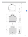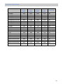
1
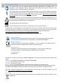
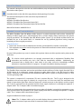
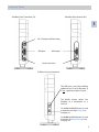
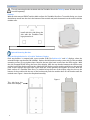
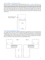
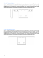
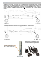
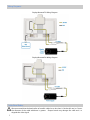
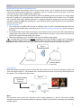
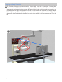
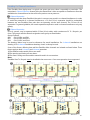
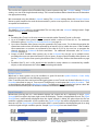
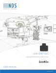
ZeroWire® Ultra High-Definition Wireless Video System User manual [ English] © 2013 NDS Surgical Imaging, LLC. All rights reserved. Information in this document has been carefully checked for accuracy; however, no guarantee is given to the correctness of the contents. This document is subject to change without notice. NDSsi provides this information as reference only. Reference to products from other vendors does not imply any recommendation or endorsement. This document contains proprietary information protected by copyright. No part of this manual may be reproduced by any mechanical, electronic, or other means, in any form, without prior written permission of NDSsi. All trademarks are the property of their respective owners. Table of Contents Tab 1 Warnings and Cautions------------------------------------------------------------------------------ ii Recycling ------------------------------------------------------------------------------------------------ ii Declarations of Conformity ------------------------------------------------------------------------iii Legal Statement ---------------------------------------------------------------------------------------iii Tab 2 About This Manual------------------------------------------------------------------------------------ 1 Intended Use and Contraindications ------------------------------------------------------------ 1 Overview------------------------------------------------------------------------------------------------- 1 Tab 3 Connector Panels-------------------------------------------------------------------------------------- 2 Installation ---------------------------------------------------------------------------------------------- 3 Power Options ----------------------------------------------------------------------------------------- 6 Wiring Diagrams--------------------------------------------------------------------------------------- 7 Cable Bend Radius ------------------------------------------------------------------------------------ 7 Setup------------------------------------------------------------------------------------------------------ 8 Typical Installation ------------------------------------------------------------------------------------ 9 All Channels In Use Indication--------------------------------------------------------------------- 9 Performance -------------------------------------------------------------------------------------------- 9 Positioning and Orientation --------------------------------------------------------------------- 10 Non Line of Sight Operation --------------------------------------------------------------------- 13 Avoiding Co-Channel Interference------------------------------------------------------------- 14 Advanced Features --------------------------------------------------------------------------------- 15 Channel Usage --------------------------------------------------------------------------------------- 16 Multi System Installation-------------------------------------------------------------------------- 16 Signal Strength -------------------------------------------------------------------------------------- 16 Tab 4 Troubleshooting ------------------------------------------------------------------------------------ 17 Tab 5 Drawings and Dimensions ----------------------------------------------------------------------- 18 Tab 6 Specifications ---------------------------------------------------------------------------------------- 19 Supported Video Modes ------------------------------------------------------------------------- 20 Optional Accessories ------------------------------------------------------------------------------ 21 Optional Accessory Kits --------------------------------------------------------------------------- 21 Cleaning and Disinfecting instructions ------------------------------------------------------- 22 Tab 7 Electromagnetic Compatibility (EMC) Tables ----------------------------------------------- 23 Contact---------------------------------------------------------------------------------------------- Back i 1 Warnings and Cautions This symbol alerts the user that important information regarding the installation and / or operation of this equipment follows. Information preceded by this symbol should be read carefully in order to avoid damaging the equipment. This symbol warns user that un-insulated voltage within the unit may have sufficient magnitude to cause electrical shock. Therefore, it is dangerous to make contact with any part inside the unit. To reduce the risk of electric shock, DO NOT remove cover (or back). There are no user serviceable parts inside. Refer servicing to qualified service personnel. This symbol cautions the user that important information regarding the operation and / or maintenance of this equipment has been included. Information preceded by this symbol should be read carefully to avoid damage to the equipment. This symbol denotes the manufacturer. This symbol denotes the manufacturer’s European Community representative. To prevent fire or shock hazards, do not expose this unit to rain or moisture. Also, do not use this unit's polarized plug with an extension cord receptacle or other outlets unless the prongs can be fully inserted. The product is designed to meet the medical safety requirements for a patient vicinity device. This product is a Class II medical device. No modifications are allowed. This equipment/system is intended for use by healthcare professionals only. Safety Compliance: This device is T.U.V. approved with respect to electric shock, fire and mechanical hazards only in accordance with CAN/CSA C22.2 No. 60601-1 and ANSI/AAMI ES60601-1. 0673 Safety Compliance: This device meets the requirements of EN60601-1 so as to conform to the Medical Device Directive 93/42/EEC and 2007/47/EC (general safety information). Radio Approval: This device meets the requirements of EN 302 065 V1.2.1 and conforms to Radio and Telecommunications Terminal Equipment (R&TTE) Directive 1999/5/EC. FCC Identification: UEZTZM7201 This product complies to the above standards only when used with the supplied medical grade power supply. Power Supply: Ault MW172KB2400F02 or Ault MW172KB2400B02 AC Input: 100 to 240 Volts at 50 to 60 Hz. DC Output: 24 volts at 0.75 amps Power Cord: Use a hospital grade power cord with the correct plug for your power source. Disconnect the power cord from the AC mains. The power cord is the only recognized disconnect device. The MEDICAL EQUIPMENT should be positioned so that its disconnect device is readily accessible. The device should be powered from a center tapped circuit when used in the US at voltages over 120 volts. This product is intended for continuous operation. Recycling: Follow local governing ordinances and recycling plans regarding the recycling or disposal of this equipment. ii Declarations of Conformity FCC and Council Directives of European Standards: This device complies with Part 15 of FCC rules and 93/42/EEC and 2007/47/EC of the Council Directives of European Standards. Operation is subject to the following two conditions: (1) This device may not cause harmful interference, and (2) this device must accept any interference received, including interference that may cause undesirable results. 1. Use the attached specified cables with the device so as not to interfere with radio and television reception. Use of other cable and adapters may cause interference with other electronic equipment. 2. This equipment has been tested and found to comply with the limits pursuant to FCC part 15 and CISPR 11under clause 3.1 and 8.5. This equipment generates, uses and can radiate radio frequency energy and, if not installed and used in accordance with the instructions, may cause harmful interference to radio communications. IEC: This equipment has been tested and found to comply with the limits for medical devices to the IEC 60601-1-2. These limits are designed to provide reasonable protection against harmful interference in a typical medical installation. This equipment generates, uses and can radiate radio frequency energy and, if not installed and used in accordance with the instructions, may cause harmful interference to other devices in the vicinity. FCC, Council Directives of European Standards and IEC: There is no guarantee that interference will not occur in a particular installation. If this equipment does cause harmful interference to radio or television reception, which can be determined by turning the equipment off and on, the user is encouraged to try to correct the interference by one or more of the following measures: Reorient or relocate the transmitter and / or the receiver. Increase the separation between the equipment and receiver. Connect the equipment into an outlet on a circuit different from that to which the receiver is connected. Consult your dealer or an experienced radio/TV technician for help. Accessory equipment connected to this device must be certified according to the respective IEC Standards, i.e. IEC 60950-1, for data processing equipment and IEC 60601-1 for medical equipment. Furthermore, all configurations shall comply with the system standard, IEC 60601-1-1. Anyone who connects additional equipment to the signal input part or signal output part configures a medical system, and is therefore responsible that the system complies with the requirements of system standard IEC 60601-1-1. Whoever is responsible for securing the device to a system needs to insure that the mounting equipment used with this device complies to IEC standard 60601-1. If in doubt, consult with your vendor’s technical service department. Legal Statement NDS sells its products through other medical device manufacturers, distributors and resellers and therefore, purchasers of this NDS product should consult with the entity through which this product was originally purchased regarding the terms of any applicable product warranties provided by such entity, if any. NDS neither assumes nor authorizes any person to assume for it any other liabilities in conjunction with and/or related to the sale and/or use of its products. To ensure proper use, handling and care of NDS products, customers should consult the product specific literature, instruction manual, and/or labeling included with the product or otherwise available. Customers are cautioned that system configuration, software, the application, customer data and operator control of the system, among other factors, affect the product’s performance. While NDS products are considered to be compatible with many systems, specific functional implementation by customers may vary. Therefore, suitability of a product for a specific purpose or application must be determined by the consumer and is not warranted by NDS. NDS SPECIFICALLY DISCLAIMS ALL WARRANTIES OF ANY KIND, WHETHER EXPRESS, IMPLIED AND/OR STATUTORY, INCLUDING, BUT NOT LIMITED TO WARRANTIES OF MERCHANTABILITY, FITNESS AND/OR OF SUITABILITY FOR A PARTICULAR PURPOSE, AND NON-INFRINGEMENT WITH RESPECT TO ALL NDS PRODUCTS OR SERVICES. ANY AND ALL OTHER WARRANTIES, REPRESENTATIONS AND/OR GUARANTEES, OF ANY TYPE, NATURE OR EXTENT, BE IT IMPLIED, EXPRESS AND/OR WHETHER ARISING UNDER OR AS A RESULT OF ANY STATUTE, LAW, COMMERCIAL USAGE, CUSTOM, TRADE OR OTHERWISE, ARE HEREBY EXPRESSLY EXCLUDED AND DISCLAIMED. NDS, its suppliers and/or distributors are not liable, directly or by way of indemnity for any special, incidental, consequential, punitive, exemplary or indirect damages, including but not limited to alleged damages for delayed shipment, non-delivery, product failure, product design or production, inability to use such products or services, loss of future business (lost profits), or from any other cause, whatsoever, in connection with or arising from the purchase, sale, lease, rental, installation or use of such NDS products, these terms and conditions, or with respect to any the terms of any agreement which incorporates these terms and conditions. SOME JURISDICTIONS DO NOT ALLOW EXCLUSIONS AND DISCLAIMERS OF CERTAIN WARRANTIES OR LIMITATIONS OF LIABILITY, SO THE LIMITATIONS AND/OR EXCLUSIONS, SET FORTH HEREIN, MAY NOT APPLY. IN THAT EVENT LIABILITY WILL BE LIMITED TO THE GREATEST EXTENT PERMITTED BY LAW IN THE SUBJECT JURISDICTION. The information provided in this document, including all designs and related materials, is the valuable property of NDS and / or its licensors and, as appropriate, they reserve all patent, copyright, and other proprietary rights to this document, including all design, manufacturing reproduction, use, and sales rights thereto, except to the extent said rights are expressly granted to others. iii About This Manual This manual is designed to assist the user with installation, setup and operation of the NDS ZeroWire® Ultra HD wireless video system. 2 A numbered tab on the side of the page denotes the beginning of a section. The functional descriptions in this manual are representative of: Part Numbers: 90T2036 = ZeroWire Ultra Receiver 90T2037 = ZeroWire Ultra Transmitter (Input: DVI ) 90T0039 = ZeroWire Ultra Transmitter (Input: DVI and 3G-SDI) Manual Part Number: 60G0535 Rev A Intended Use and Contraindications The NDSsi ZeroWire Ultra HD Wireless Video System is a paired transmitter and receiver, intended for delivery of video signals over a radio-frequency link to a video display during endoscopic and general surgical procedures. The ZeroWire Ultra HD Wireless Video System is a non-sterile reusable device not intended for use in the sterile field. It is intended for use by qualified physicians having complete knowledge of these surgical procedures. Contraindications: 1. These units are non-sterile reusable devices and are not intended for use within a sterile field. 2. This equipment may not be used in the presence of flammable anesthetics mixture with air, oxygen or nitrous oxide. No part of this product may come in contact with a patient. Never touch the product and a patient at the same time. For mission critical applications, we strongly recommend that a replacement ZeroWire Ultra transmitter and receiver pair, and a DVI cable be immediately available. Additionally, we recommend that a display that is hard wired to the video source be immediately available whenever a surgical procedure is in progress. See typical installation drawing on page 9. Overview The ZeroWire Ultra transmitter and receiver pair allows wireless delivery of video signals from the DVI or 3G-SDI output of an endoscopic camera processor or other video source to the DVI input of a video display. It operates as an unlicensed ultra-wideband (UWB) wireless system in compliance with FCC (Part 15) rules governing UWB. The system is composed of a transmitter (Tx) and a receiver (Rx) pair. The Tx unit is designed to be mounted on the rear top edge of a display on a surgical cart, or on the cart itself. The transmitter may obtain its input video signal from either an endoscopic camera processor or the display’s re-drive output. The Tx unit is powered from the provided 24 VDC power supply (“wall-wart”) or through the optional ‘Y’ adapter cable*. The ‘Y’ adapter cable is described on page 6. The Rx unit is designed to be mounted on the rear top edge of a display, it may also be mounted on a cart, and is powered from the provided 24 VDC power supply (“wall-wart”) or through the optional ‘Y’ adapter cable*. The ‘Y’ adapter cable is described on page 6. A typical installation is shown on page 9. *Note: The ‘Y’ adapter cables are for use with displays that are powered by 24 VDC and whose power connector accepts one of the J2 connectors shown on page 6. 1 Connector Panels ZeroWire Ultra Transmitter (Tx) ZeroWire Ultra Receiver (Rx) 3 3G– SDI input (90T2016 only) DVI input DVI output Power connector Tx & Rx Common Connectors The USB port is used for installing updates to the Tx or Rx firmware. It is not a general purpose I/O port The BOND button allows the bonding of a transmitter to a receiver. On the Tx the BOND button is used to wake the unit from Deep Sleep. See page 15. On the Rx the BOND button is used to activate the Signal Strength bar. See page 16. 2 Installation The only mounting bracket included with the ZeroWire Ultra is the Desktop mount. All other brackets are sold separately. Desktop: With the side stamped FRONT and the black surface of a ZeroWire Ultra Rx or Tx module facing you, insert the desktop mount into the slot in the bottom of the module and push downwards on the mount until the module seats. Install with this side facing the side with the ZeroWire Ultra logo printed on it. Optional Mounting Brackets: Extended Height Bracket for 24” and 26” Radiance Displays: Each step bracket is stamped with a part number (P/N). For Radiance 24” and 26” displays, select the extended height step bracket P/N 20C0669 . Replace the left hand mounting screws with 2 of the provided mounting screws. Do not tighten them. Remove the two right hand screws from the VESA mount . With the side stamped FRONT facing the front of the display, slide the step bracket between the VESA mount and the back of the display until notches labeled for the display you are working with fit over the two left hand screws. Replace the right hand screws with the screws provided and tighten all screws. With the black surface of a ZeroWire Ultra Rx or Tx module facing the front of the display, align the slot on the bottom of the module with the top of the bracket and push the module down on the bracket until the module seats. Figure 1 shows the completed assembly. Figure 1 This side faces the front of the display. 3 19” and 23” Radiance and 24” EndoVue Display: Each step bracket is stamped with a part number (P/N). For Radiance 19” and 23” and EndoVue 24” displays, select step bracket P/N 20C0660. Replace the left hand mounting screws with 2 of the provided mounting screws. Do not tighten them. Remove the two right hand screws from the VESA mount . With the side stamped FRONT facing the front of the display, slide the step bracket between the VESA mount and the back of the display until notches labeled for the display you are working with fit over the two left hand screws. Replace the right hand screws with the screws provided and tighten all screws. With the black surface of a ZeroWire Ultra Rx or Tx module facing the front of the display, align the slot on the bottom of the module with the top of the bracket and push the module down on the bracket until the module seats. This side faces the front of the display. “L” Bracket for 24” and 26” Radiance Displays: The “L” bracket P/N 20C0830, like the Extended Height Bracket (P/N 20C0669), raises the installed height of the ZeroWire Ultra unit by 2.4” (61mm) to improve the ZeroWire Ultra transmitter’s coverage and the ZeroWire Ultra receiver’s reception. The “L” bracket also offsets the ZeroWire Ultra unit to the left (Figure 1) of the display’s center for improved boom arm clearance. If desired the “L” bracket may be reversed to offset the ZeroWire Ultra unit to the right (Figure 2) of the display’s center. Installation of the “L” bracket is the same as described on the previous page for the standard height bracket. Figure 1 Figure 2 4 32” and 37” Radiance Displays: Select ‘T’ bracket (P/N 20C0684). Lay the display face down on a clean surface. Center the ‘T’ bracket on the top edge of the display and remove the 2 screws that are aligned with the holes in the bracket. Insert the provided screws through the bracket and case back. Tighten both screws. With the black surface of a ZeroWire Ultra Rx or Tx module facing the front of the display, align the slot on the bottom of the module with the top of the bracket and push the module down on the bracket until the module seats. 42”, 52” and 55” Radiance Displays: Select ‘T’ bracket (P/N 20C0668). Lay the display face down on a clean surface. Center the ‘T’ bracket on the top edge of the display and remove the 2 screws that are aligned with the holes in the bracket. Insert the provided screws through the bracket and case back. Tighten both screws. With the black surface of a ZeroWire Ultra Rx or Tx module facing the front of the display, align the slot on the bottom of the module with the top of the bracket and push the module down on the bracket until the module seats. 5 Power Options ZeroWire Ultra transmitters and receivers may be powered from the provided power supply (pictured below), or when used with an NDS display they may be powered from the display’s power supply via the supplied ‘Y’ adapter cable. ‘Y’ adapter cables, shown below, are available for Radiance 19”, 24”, 26” and 32” displays and Endovue 24” display. ‘Y’ adapter cables are not available for 37”, 42”, 52” or 55” Radiance displays. ‘Y’ adapter cable (35X0096) for 19”, 24” and 26” Radiance Displays and 24” EndoVue Display ‘Y’ adapter cable (35X0097) for Radiance 26 G2 HB, 26 D HB and 32” Radiance Display When using the included power supply, select and install the plug adapter that matches the wall socket in your OR. Provided power supply or J3 of the ‘Y’ adapter connects here. 6 Wiring Diagrams Display Mounted Tx Wiring Diagram Display Mounted Rx Wiring diagram Cable Bend Radius We recommend that the bend radius of metallic cables be no less than 2.5 inches (63 mm) or 7 times the diameter of the cable whichever is greater. Sharper bends may damage the cable and / or degrade the video signal. 7 Setup Bonding the Transmitter (Tx) and Receiver (Rx) Before the ZeroWire Ultra wireless system can be put into service , the Tx and Rx pair must be bonded. Connect an included power supply or a ‘Y’ Adapter cable to a Tx and an Rx unit. See page 7 for Power Connector location and ‘Y’ Adapter cable information. The status indicator LED of each unit should be yellow and blinking slowly. If the LED’s are steady yellow then the Tx and Rx pair is already bonded, continue at the Passing Video section below. Once a Tx and Rx pair is bonded, they remain bonded until the Tx is explicitly bonded to another Rx or the Rx is explicitly bonded to another Tx. Note: If a bonded pair is turned off they will automatically bond to each other when they are turned on again. Bonding Procedure: 1. First, verify that a ZeroWire Ultra channel is available. If the Tx’s LED is alternating between blue and yellow, then all ZeroWire Ultra channels are in use. See All Channels In Use Indication section on page 9 for details. 2. Press and hold the “bond” button (see Figure 1 for location) on the Tx unit until its LED begins flashing rapidly, then release. Next press and hold the “bond” button (see Figure 1 for location) on the Rx unit until its LED begins flashing rapidly, then release. 3. When the bonding process is complete each unit’s LED will be steady yellow. ZeroWire Ultra Tx and Rx units are not compatible with earlier ZeroWire Tx and Rx units. Attempting to bond a ZeroWire Ultra unit to an earlier ZeroWire unit will cause the ZeroWire Ultra unit’s LED to blink Yellow twice, then turn steady Yellow for one second, after which the pattern is repeated. Figure 1 Tx Rx Bonding Button Press here Passing Video: With the bonding completed, connect a DVI or SDI video source to the Tx unit and a display to the Rx unit via its DVI output (Figure 2). The indicator LED’s should turn blue and the source image should appear on the display. This completes the basic setup. Figure 2 Endoscope Processor Tx Rx Note: The transmitter and receiver are not limited to line-of-sight operation, i.e., the pair will operate reliably despite the presence of intervening obstacles. However, neither unit should be completely surrounded by metallic objects. 8 Typical Installation Detailed Installation and Setup information starts on the following page. Transmitter Receiver Display hardwired to image source (processor). NDSsi recommends ZeroWire Ultra for primary and secondary displays. However, for patient safety a display that is cable connected to the video source shall be immediately available whenever a surgical procedure is in progress. All Channels In Use Indication Tx Indication: 1. When all channels are in use and a new ZeroWire Ultra pair or a new Tx is turned on: The LED on the Tx will alternate between blue and yellow continuously or until it finds a free channel. If a free channel is found, then the LED will behave as described in Bonding Procedure on page 8. 2. When all channels are in use and the bonding button is pressed on a new Tx: The LED on the Tx blinks fast yellow, indicating that the device is attempting to bond. If no channel is found, then the LED blinks alternately between blue and yellow until the bonding times out. If an available channel is found, then the LED will behave as described in Bonding Procedure on page 8. Rx Indication: Rx is not aware that all channels are in use. Performance Performance: ZeroWire Ultra HD Wireless Video System products are intended and optimized for use in a surgical operating room (OR). Use outside of an OR environment is not recommended. The following steps will help you to achieve optimal performance of the ZeroWire Ultra system: 1. Mount both components at least 5 feet (1.5 m) from the floor. 2. Ideally, both the transmitter and receiver should be at the same height. 3. For a reliable video link, the distance between transmitter and receiver should be 30 feet (10 m) or less . 4. The black surfaces of the transmitter and receiver should be vertical, facing each other and be visible to each other in free air space. We do not recommend orienting the modules horizontally. 5. For non line of sight applications, we recommend that the Tx and Rx be located no more than 6 feet (1.8 m) from the walls of the OR. 9 Positioning and Orientation Due to the shape of the antenna’s signal field (image 1), both Tx and Rx units should be installed so they are vertical within + or - 10°, and horizontal within + or - 10°. Vertical Alignment: Vertical alignment should be within + or - 10° of vertical. See image 2. Horizontal Alignment: Horizontal alignment should be within + or - 10° of horizontal. See image 3. Positioning and Orientation is continues on the following page. 10 Elevation: The Tx and Rx should be positioned at least 5 feet (1.5 m) above the floor, be at the same height, and, preferably, with the black (front) surfaces of the Tx and Rx facing directly at each other. Separation: ZeroWire Ultra operates correctly with a Tx and Rx separation of up to 30 feet (10 m). However, in the case of most OR environments, best results are achieved with a Tx and Rx separation distance of up to 8 feet (2.4 m). Positioning and Orientation is continues on the following page. 5 inches (127 mm) minimum 5 inches (127 mm) minimum Up to 8 ft. (2.4 m) At least 5 ft. (1.5 m) 11 At least 5 ft. (1.5 m) Test results indicate that ZeroWire Ultra achieves a better signal-to-noise ratio when the Tx and Rx are oriented at certain angles relative to one another. Optimum link quality is achieved when the Tx and Rx are aligned at 0° relative to each other. Acceptable link quality is achieved when the Tx and Rx are aligned at angles between 0 to 45°, 130° and 180° relative to each other. Aligning the Tx and Rx at 90° relative to each other provides the least acceptable link quality. 12 Non Line of Sight Operation The ZeroWire Ultra system can maintain a wireless link even with obstructions. However, best performance is realized with a clear line-of-sight. In an OR environment, the ceiling mounted boom system and its spring arm junctions, along with surgical light heads, are large metal structures that can potentially block RF signals if they obstruct the line-of-sight between the Tx and Rx (see image 1 below). Preferably, the surgical lights should be positioned out of the way or raised above the line-of-sight. If an object must obstruct the line-of-sight, the best option is to position it half way between the Tx and the Rx. 13 Avoiding Co-Channel Interference If the ZeroWire Ultra deployment is a typical one-system per room, there is essentially no restriction. The transmitter’s Channel Selection feature picks the channel that is least susceptible to interference from the available nine channels based on the result of its passive scan at power on. 3 Channel Operation: Operating more than three ZeroWire Ultra pairs in one area may result in co-channel interference. In order to avoid the potential of co-channel interference, a 75 foot (23 m) separation should be maintained between any two ZeroWire Ultra pairs that are operating on the same channel. The 75 foot (23 m) separation is a general guideline, the actual separation required to avoid co-channel interference may vary greatly. 9 Channel Operation: Up to 9 systems, may be operated within 75 feet (23 m) radius, with a maximum of 3 Tx / Rx pairs per room. The groups and the channels assigned to each group are listed below. Group Channels GR0 CH13, CH74, and CH9 GR1 CH14, CH73, and CH11 GR2 CH15, CH72, and CH10 The drawings below may be used as references for actual installations. For 3 channel installations use drawing 1. For 9 channel installations drawings 1 and / or 2 may be used. Some of the factors affecting how well the ZeroWire Ultra channels are isolated are listed below. These factors apply to both 3 channel and 9 channel operation. 1) The thickness and material of the room walls. 2) The opening and closing of room doors. 3) The room’s ceiling structure and the materials used in its construction. Note: ZeroWire Ultra Tx / Rx pairs must be installed in the same room. Cross room operation is not supported Channel 13 Group 0 Group 0 Channel 14 Channel 15 Group 1 Group 1 Channel 13 Channel 14 Channel 15 Group 2 Group 2 14 Advanced Features Overview: The Update Channel / Power Utility software and its usage instructions are on the CD included in the ZeroWire Ultra shipping box. The utility allows the user to configure some of ZeroWire Ultra transmitter and receiver parameters. The parameter settings are discussed in the following paragraphs. Note: These settings can only be changed using a computer to connect to a ZeroWire Ultra unit and running the Update Channel / Power Utility software. Channel Selection (Tx only): The user may select either the 3 channel or 9 channel option. The channel list for the 3-channel option is: 13 14 15, and the list for the 9-channel option is: 13 74 9 14 73 11 15 72 10. 9-channel is the default for ZeroWire Ultra. Note: ZeroWire Ultra Tx and Rx units are not compatible with earlier ZeroWire Tx and Rx units. Deep Sleep Selection (Tx only): The ZeroWire Ultra Tx goes into Deep Sleep after 3 minutes if no video input is detected, or if its corresponding Rx unit is powered off, or disconnected from the receiving display. Restoring video will “wake up” the Tx. The Deep Sleep feature is always ON and cannot be turned OFF Note: When the TX unit is in the Deep Sleep state, its LED’s cadence will be: blinking yellow for 1 second, then off for 3 seconds. To wake the Tx unit, press its bonding button and the TX’s LED switches to blinking amber. Also, restoring video will bring the Tx out of the sleep state. ATPC Selection (Tx & Rx): When ATPC set to OFF, the system will operate at maximum transmit power, making the wireless link more robust when obstructions to the line-of-sight are introduced. When ATPC is set to ON, the system transmits at a lower power level determined by the relative distance and signal quality between the Tx and Rx units. The advantage of having ATPC ON is that it allows more ZeroWire Ultra systems to operate in the same area by minimizing the transmit power and decreasing the potential for co-channel interference. The RX unit’s ATPC setting automatically matches the TX unit ‘s ATPC setting. 15 Channel Usage The user has the option to have ZeroWire Ultra systems operate using the 9 channel setting, 3 Channel setting, or a one of the single channel settings. The recommendations below should be used to determine the appropriate setting. We recommend using the default 9-channel setting. The 9-channel setting allows the Channel Selection feature to pick, based on the result of the transmitter’s passive scan at power on, the channel that is least susceptible to interference. Operating three pairs or less: The default 9-channel setting is recommended. The user may select the 3-channel setting instead. Single channel settings are not recommended. Notes: 1. ZeroWire Ultra Tx and / or Rx units cannot be used with earlier Zerowire Tx and / or Rx units. 2. Up to 9 ZeroWire Ultra systems may be operated within a radius of 75 feet (23 m) . For additional information refer to Avoiding Co-channel Interference on page 14. 3. Up to three ZeroWire Ultra systems may be operated in the same room. For 9 channel operation the transmitters and receivers should be separated by at least 8 ft (2.5 m) within the room. If the ZeroWire Ultra transmitters or receivers are separated by less than 8 ft (2.5 m), the user has to program the channel selection to 3-channel for each transmitter. For additional information refer to Channel Selection on page 15. 4. Groups of three ZeroWire Ultra systems run on the 9-channel list may be set in multiple rooms, providing the rooms are spaced at least 25 ft (7.6 m) apart. Groups of three ZeroWire Ultra systems run on the 3-channel list, the room spacing should be at least 75 ft (23m). Refer to the illustrations on page 14. 5. ZeroWire Ultra Tx and / or Rx should not be installed in metal cabinets or surrounded by metallic objects, as this will prevent the Tx from communicating with the Rx Multi System Installation Multiple Systems: When two or three systems are to be installed in a given OR and the Update Channel / Power Utility software is not available, use the following procedure: If the Tx and Rx units have not been bonded apply power to one Tx and one Rx then follow the Bonding Procedure described on page 9. Turn second Tx and Rx pair on and repeat the Bonding Procedure. Turn on the third pair and repeat the Bonding Procedure. Tx and Rx pairs must be bonded one pair at a time. We recommend that bonded pairs be labeled to facilitate installation and troubleshooting. Signal Strength Momentarily pressing the Rx’s bond button displays the channel the Rx is operating on and a Signal Strength bar to its right in the lower right corner of the display. The bar is displayed 60 seconds. The Signal Strength bar is automatically displayed when the signal strength is below the point where the Rx can maintain a reliable connection. In this condition the Signal Strength bar will be displayed for 60 seconds, then turn off. The Signal Strength bar will remain off for 1 second, and then be displayed again for as long as the low signal strength condition persists. Sample Signal Strength bars are shown below. Excellent link quality. Good link quality. Acceptable link quality, some pixilation may occur. Link down or poor link quality, frequent pixilation and/or screen “freeze”. 16 Troubleshooting Problem Possible Causes Indicator LED is not on. Loose Power Connector: Verify that the power source connector is fully inserted into the unit’s power connector. 'Y' Cable: If you are using the ‘Y’ cable to supply power to the unit, confirm that it is connected to a power supply and that the power supply is energized. Stand Alone Power Supply: If the stand alone power supply is being used confirm that it is fully inserted into the wall socket. 4 Wall Socket: Some wall sockets have on / off switches built in. If the socket you are using has a built in switch, check that it is in the on position. Additional Information: See Power Options on page 6. Poor or intermittent video Possible causes Remedial Action Tx and RX are spaced more than 30 Reduce the spacing between the Tx and Rx to 30 feet (10 m) or less. See Tx feet (10 m) apart. to Rx Range specification on page 19. Tx and Rx are not aligned properly See Tx / Rx alignment recommendations on page 12. DVI or SDI (Tx only) connections Confirm that the cables are properly connected. Unsupported video mode Verify that the applied video mode is supported. See the Supported Video Modes table on page 20. DVI or SDI (Tx only) cables Replace the cables one at a time and check the video display. If the video signal displays properly after a cable is replaced, discard the cable you just replaced. Crosstalk See Avoiding Co-Channel Interference on page 14 Low signal strength See Signal Strength on page 16. The Tx and Rx are switched Verify that the video source is connected to the Tx, not the Rx. LED Indicators LED State Description Yellow and blinking slowly The unit is not bonded. See Bonding Procedure on page 8. Yellow and flashing rapidly Unit is attempting to bond. See Bonding Procedure on page 8. Yellow and steady Unit is bonded and communicating with another unit. See page 8. Blue and steady The unit is sending (Tx) or receiving (Rx) video data. Blue and blinking slowly The source is sending an encrypted signal. Encrypted signals are copyrighted and may not be re-transmitted. Alternating Blue and Yellow All channels are in use. This state applies to transmitters only. See page 9. Blinking yellow for 1 second, then off for 3 seconds This state applies to the Tx only and indicates that the Tx is in Deep Sleep. See page 15 Bonding incompatibility. Indicates an attempt to bond an Ultra unit with an earlier unit. See Bonding Procedure on page 8. Alternating steady Yellow and fast blinking Yellow 17 Drawings and Dimensions Both Units 5 Transmitter Receiver 18 Specifications 6 Wireless Signal Type Ultra Wideband (UWB) Frequency Band 3.1 to 4.8 GHz Number of Channels 9 (For 3 channel operation, see page 15.) RF Power Out (maximum) -41.25 dBm / MHz Tx to Rx Range (Line of sight not required) Up to 30 ft (10 m) a Data Rate 53.3 to 480 Mbps System Latency < 1 frame Compression Technology H.264 Super Low Latency Technology™ b Hardware Encryption 128 bit AES Video Inputs (Transmitter) DVI, 3G SDI , HD-SDI and SDI Video Outputs (Receiver) DVI Power Consumption 14 Watts (Max) DC Power Supply 100-240VAC 50/60Hz input 24V @ .75A DC (18 watts) output Physical Dimensions 7.04” x 7.40” x 1.43” (178.9mm x187.9mm x 36.4mm) ZeroWire Ultra Weight (Tx or Rx) excluding base 1.4 lbs (0.64 Kg) Mounting Base Weight 0.8 lbs (0.36 Kg) Operating Temperature 50° to 95° F (10° to 35° C) Operating Humidity 10% to 80% RH, non-condensing Operating Altitude 6,600 ft (2,000 m) Storage Temperature -4° to 140° F (-20° to 60° C ) Storage Humidity < 70% RH (non-condensing) Transport Humidity < 70% RH (non-condensing) Storage Altitude 33,000 ft (10,000 m ) a. The effective range may vary depending upon the environment in which the product is operating. Follow the product’s Setup section to achieve optimum performance and range. b. Super Low Latency Technology is a trademark of Cavium Networks, Inc. 19 Supported Video Modes Name 1080p60 1080p50 1080p30 1080p25 1080p60 special mode 1080p50 special mode 1080i30 1080i25 720p60 720p50 480p60 576p50 VGA SVGA XGA SXGA Special camera mode Horizontal Active Pixels 1920 1920 1920 1920 1920 1920 1920 1920 1280 1280 720 720 640 800 1024 1280 1440 Horizontal Total Pixels 2200 2640 2200 2640 2184 2270 2200 2640 1650 1980 870 864 800 1056 1344 1688 1904 Vertical Active Pixels 1080 1080 1080 1080 1080 1080 1080 1080 720 720 480 576 480 600 768 1024 900 Vertical Total Pixels 1125 1125 1125 1125 1125 1125 562 562 750 750 525 625 525 628 806 1066 932 Frame / Field Rate ( Hz) Special camera mode 1024 1124 1024 1068 30 Special camera mode 1024 1152 1024 1250 25 Special camera mode 1280 1800 1024 1200 50 60 50 30 25 60 50 60 50 60 50 60 50 60 60 60 60 60 20 Optional Accessories Part Number 20C0660 20C0684 20C0668 20C0669 20C0830 26B0099 30B0038 35X0096 35X0097 35D0073 35D0081 35D0091 35D0092 35D0093 60A0374 Description VESA Mount Bracket for 19" and 23" Radiance Displays and 24" EndoVue Display Top Mount Bracket for Radiance 32" and 37" Radiance Displays Top Mount Bracket for Radiance 42", 52" and 55" Radiance Displays Extended Height Bracket for 24” and 26” Radiance Displays: “L” Bracket for 24” and 26” Radiance Displays: Spare Table Stands Spare Power Supply 'Y' Adapter Cable for 19", 24" and 26" Radiance Displays and 24" EndoVue Display 'Y' Adapter Cable for 32" Radiance Display 6ft DVI Cable 6ft 3G-SDI Cable Spare 3ft DVI Cable Spare 2ft DVI Cable Spare 3ft SDI Cable Printed ZeroWire Ultra Users Manual See Page 4 5 5 3 4 3 6 6 6 Contact NDS Sales for price and availability. Contact information is on the back cover. Optional Accessory Kits Part Number Description and Contents 90Z0118 Packaged ZeroWire Ultra Accessory Kit for 24" and 26" NDS displays 20C0669 VESA Mounting Brackets 35X0096 'Y' Adapter Cable 3ft (0.91m) DVI Cable 3ft (0.91m) SDI Cable Qty 2 2 2 1 90Z0119 Qty 90Z0120 Packaged ZeroWire Ultra Accessory Kit for 32" and 37" NDS displays 20C0684 Top Mount Bracket for Radiance 32" and 37" Radiance Displays 35X0097 'Y' Adapter Cable 3ft (0.91m) DVI Cable 3ft (0.91m) SDI Cable 2 2 2 1 Packaged ZeroWire Ultra Accessory Kit for 42", 52" and 55" NDS displays Qty 20C0668 Top Mount Bracket for Radiance 42", 52" and 55" Radiance Displays 3ft (0.91m) DVI Cable 3ft (0.91m) SDI Cable 90Z0121 Packaged ZeroWire Ultra Accessory Kit for 19" and 23" Radiance and 24" EndoVue displays 20C0660 VESA Mounting Brackets 35X0096 'Y' Adapter Cable 3ft (0.91m) DVI Cable 3ft (0.91m) SDI Cable Contact NDS Sales for price and availability. Contact information is on the back cover. 21 2 2 1 Qty 2 2 2 1 Cleaning and Disinfecting Instructions Prior to cleaning and surface disinfection, the unit should be turned OFF and disconnected from its power source. Cleaning: Thoroughly wipe all exterior surfaces with a lint-free cloth that has been dampened with an acceptable cleaning agent. Acceptable cleaning materials are listed below. Remove residual detergent by wiping all exterior surfaces with a lint-free cloth dampened with distilled water. Disinfecting: Disinfect the unit by wiping all exterior surfaces with a lint-free cloth dampened with 80% Ethyl Alcohol. Allow the unit to air dry. Cautions: Do not allow liquids to enter the interior of the unit, and do not permit exterior surfaces to come into contact with unacceptable solvents such as those listed below, as severe damage to the unit may result. Acceptable Cleaning Materials: Vinegar (distilled white vinegar, 5% acidity) Ammonia-based glass cleaner Acceptable Disinfecting Material: Ethanol 80 % by volume Unacceptable solvents: MEK (Methyl Ethyl Ketone) Toluene Acetone *Note: The acceptable cleaning and disinfecting materials listed above have been tested on NDS products and, when used as directed, do not harm the product’s finish and or its plastic components. 22 Electromagnetic Compatibility (EMC ) Tables ZeroWire Ultra has been tested in an OR environment and did not interfere with electrosurgical, ultrasound, X-Ray, medical displays and life monitoring equipment. Neither did the aforementioned equipment interfere with ZeroWire Ultra. Additionally, since ZeroWire Ultra operates in 3.1 – 4.8 GHz, typically wireless LAN and mobile phones will not cause interference as they operate outside the ZeroWire Ultra frequency range. However, the presence of a source of interference within ZeroWire Ultra frequency range may result in intermittent operation and reduced image quality or the link could go down while the interference exists. Prior to any procedure in the OR, it is required that any such equipment be turned off and verify that the system operates as expected. If any anomalous behavior is observed, it must be corrected prior to using the system in any surgical procedures. ZeroWire Ultra transmitters should be separated by at least 20 inches (.5 m). ZeroWire Ultra transmitters (Tx) or receivers (Rx) should not be installed in metal cabinets or surrounded by metallic objects, as this will prevent the Tx from communicating with the Rx. During installation the ZeroWire Ultra link video quality should be tested with the Tx and Rx at different orientation angles, acceptable orientation angles are shown on page 12. Non Line of Sight Operation is discussed on page 13. We recommend that the system be thoroughly tested prior to using it in any surgical procedures. 7 Do not use power supplies or cable accessories with the ZeroWire Ultra other than those specified in this manual. Excessive leakage currents, elevated electromagnetic emissions, or insufficient interference immunity may occur. All medical electronic devices, including ZeroWire Ultra, must conform to the requirements of IEC 60601-12. Precautions, adherences to the EMC guideline information provided in this manual and verification of all medical devices in simultaneous operation are required to ensure the electromagnetic compatibility and co-existence of all other medical devices prior to a surgical procedure. The EMC tables on the next three pages are provided for your reference. 23 EMC Tables Guidance and manufacturer’s declaration – electromagnetic emissions The product is intended for use in the electromagnetic environment specified below. The customer or the user of the product should assure that it is used in such an environment. Emissions Compliance RF emissions CISPR 11 Group 1 RF emissions CISPR 11 Class A Harmonic emissions IEC 61000-3-2 Not Applicable Voltage fluctuations/ flicker emissions IEC 61000 -3-3 Electromagnetic environment-- guidance The product uses RF energy only for its internal function. Therefore, its RF emissions are very low and are not likely to cause any interference in nearby electronic equipment. The product is suitable for use in all establishments, including domestic establishments and those directly connected to the public low-voltage power supply network that supplies buildings used for domestic purposes. Not Applicable Guidance and manufacturer’s declaration 211; electromagnetic immunity The product is intended for use in the electromagnetic environment specified below. The customer or the user of the product should assure that it is used in such an environment. Immunity test IEC 60601 test level Compliance level Electromagnetic environment guidance Electrostatic discharge (ESD) IEC 61000-4-2 ±6 kV contact ±8 kV air ±6 kV contact ±8 kV air Floors should be wood, concrete or ceramic tile. If floors are covered with synthetic material, the relative humidity should be at least 30 %. Electrical fast transient/burst IEC 61000-4-4 ±2 kV for power supply lines ±2 kV for power supply lines Mains power quality should be that of a typical commercial or hospital environment. Surge IEC 61000-4-5 ±1 kV line(s) and neutral ±1 kV line(s) and neutral Mains power quality should be that of a typical commercial or hospital environment. Voltage dips, short interruptions and voltage variations on power supply input lines IEC 61000-4-11 <5 % UT (>95 % dip in UT) for 0,5 cycle 40 % UT (60 % dip in UT) for 5 cycles 70 % UT (30 % dip in UT) for 25 cycles <5 % UT (>95 % dip in UT) for 5s 3 A/m <5 % UT (>95 % dip in UT) for 0,5 cycle 40 % UT (60 % dip in UT) for 5 cycles 70 % UT (30 % dip in UT) for 25 cycles) <5 % UT (>95 % dip in UT) for 5s Mains power quality should be that of a typical commercial or hospital environment. If a dips or an interruption of mains power occurs, the current of the product may be dropped off from normal level, it may be necessary to use uninterruptible power supply or a battery. Not applicable Not applicable Power frequency (50/60 Hz) magnetic field IEC 61000-4-8 NOTE UT is the a.c. mains voltage prior to application of the test level 24 EMC Tables Guidance and manufacturer’s declaration – electromagnetic immunity The product is intended for use in the electromagnetic environment specified below. The customer or the user of the product should assure that it is used in such an environment. Immunity test IEC 60601 test level Compliance level Conducted RF IEC 61000-4-6 3 Vrms 150 kHz to 80 MHz 3 Vrms Radiated RF IEC 61000-4-3 3 V/m 80 MHz to 2.5 GHz Electromagnetic environment – guidance Portable and mobile RF communications equipment should be used no closer to any part of the product, including cables, than the recommended separation distance calculated from the equation applicable to the frequency of the transmitter. Recommended separation distance 3 V/m where P is the maximum output power rating of the transmitter in watts (W) according to the transmitter manufacturer and d is the recommended separation Distance in metres (m). Field strengths from fixed RF transmitters, as determined by an electromagnetic site survey,a should be less than the compliance level in each frequency range.b Interference may occur in the vicinity of equipment marked with the following symbol: NOTE 1 At 80 MHz and 800 MHz, the higher frequency range applies. NOTE 2 These guidelines may not apply in all situations. Electromagnetic propagation is affected by absorption and reflection from structures, objects and people. a. Field strengths from fixed transmitters, such as base stations for radio (cellular/cordless) telephones and land mobile radios, amateur radio, AM and FM radio broadcast and TV broadcast cannot be predicted theoretically with accuracy. To assess the electromagnetic environment due to fixed RF transmitters, an electromagnetic site survey should be considered. If the measured field strength in the location in which the product is used exceeds the applicable RF compliance level above, the product should be observed to verify normal operation. If abnormal performance is observed, additional measures may be necessary, such as re-orienting or relocating the product. b. Over the frequency range 150 kHz to 80 MHz, field strengths should be less than 3 V/m. 25 EMC Tables Recommended separation distances between portable and mobile RF communications equipment and the product The product is intended for use in an electromagnetic environment in which radiated RF disturbances are controlled. The customer or the user of the product can help prevent electromagnetic interference by maintaining a minimum distance between portable and mobile RF communications equipment (transmitters) and the product as recommended below, according to the maximum output power of the communications equipment. Rated maximum output power (W) of transmitter Separation distance, in meters according to frequency of transmitter 150 kHz to 80 MHz 80 MHz to 800 MHz 800 MHz to 2.5 GHz 0.01 0.12 0.12 0.23 0.1 0.38 0.38 0.73 1 1.2 1.2 2.3 10 3.8 3.8 7.3 100 12 12 23 For transmitters rated at a maximum output power not listed above, the recommended separation distance d in meters (m) can be estimated using the equation applicable to the frequency of the transmitter, where P is the maximum output power rating of the transmitter in watts (W) according to the transmitter manufacturer. NOTE 1 At 80 MHz and 800 MHz, the separation distance for the higher frequency range applies. NOTE 2 These guidelines may not apply in all situations. Electromagnetic propagation is affected by absorption and reflection from structures, objects and people. 26 ISO 9001:2008 and ISO 13485:2003; FDA Registration # 2954921 & 1226517 60G0535 Corporate Headquarters 5750 Hellyer Avenue San Jose, CA 95138 (USA) Tel: 408 776 0085 Toll Free: 866 637 5237 Email: [email protected] Europe Nijverheidscentrum 28 2761 JP Zevenhuizen (ZH) The Netherlands Tel: + 31 180 63 43 56 Email: [email protected] Asia Pacific 1F KDX Shiba-Daimon Building 2-10-12 Shiba-Daimon, Minato-Ku Tokyo 105-0012, Japan Tel: +81-3-6402-9892 Email: [email protected] E