1
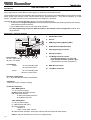
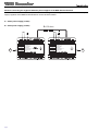
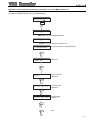
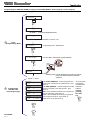
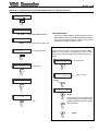
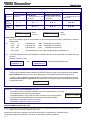
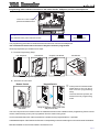
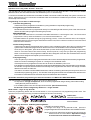
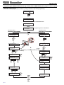
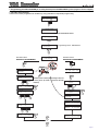
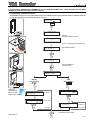
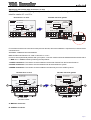
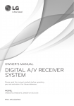
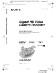
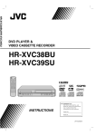
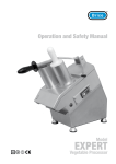
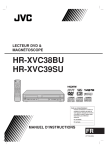
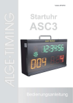
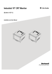
VDS DECODER INSTALLATION MANUAL ENGLISH VDS VDS Decoder MDS-VDS DECODER Code 97651Ib V01_12 This technical document of an informative nature is published by FERMAX ELECTRONICA S.A.E., who reserve the right to modify the technical characteristics of the products referred to herein at any time and without prior notice. These changes will be reflected in subsequent editions of this document. Page 2 VDS VDS Decoder TABLE OF CONTENTS VDS DECODER ref. 2409 .......................................................................................................................................... 4 - Introduction ............................................................................................................................................................ 4 - Description and Technical Features ........................................................................................................................ 4 OPERATION AS A RANGE DECODER - MDS-VDS SYSTEM .................................................................................... 7 - Overview ................................................................................................................................................................. 8 - Remember that before programming, the decoder should be in RANGE Decoder Mode ......................................... 9 - Programming the VDS Decoder (as range) from the MDS DIGITAL panel. ............................................................ 10 * Appendix l: Interior Block Programming under Option "C" via the MDS DIGITAL Panel .................................... 11 - Programming the VDS Decoder (as range) from the MDS DIGITAL panel. ............................................................ 12 * Appendix l: Programming the MDS DIRECT panel as a General Entrance / more than one GE ....................... 13 - Programming VDS residential terminals via the interior blocks’ VDS panel, monitors and telephones. ................. 15 - Programming VDS residential terminals via the general entrance’s MDS DIGITAL panel. ..................................... 16 - Programming VDS residential terminals via the general entrance’s MDS DIRECT panel. ...................................... 17 OPERATION AS AN 8 OUTPUT AUDIO DECODER ................................................................................................. 19 - Overview ............................................................................................................................................................... 19 - Remember that before programming, the decoder should be in RANGE Decoder Mode ....................................... 19 - Programming can be done in different ways ................................................................................................. 19 1. Programming the VDS DECODER 2. Programming residential terminals and the VDS DECODER 3. DEFERRED Programming of residential terminals and the VDS DECODER 4. Reprogramming Development: 1. Programming the VDS DECODER ................................................................................................................ 20 * Programming the VDS DECODER (as an 8 way decoder) via the MDS DIGITAL panel. .............................. 20 - Individual Programming ....................................................................................................................... 20 - Sequential Programming ..................................................................................................................... 20 * Programming the VDS DECODER (as an 8 way decoder) via the MDS DIRECT panel ................................ 21 - Individual Programming ....................................................................................................................... 21 - Sequential Programming ..................................................................................................................... 21 2. Programming residential terminals and the VDS DECODER (as an 8 way decoder) via the GE MDS Digital panel. ...... 22 2. Programming residential terminals and the VDS DECODER (as an 8 way decoder) via the GE MDS Direct panel. ..... 23 3. DEFERRED programming of residential terminals and the VDS DECODER (as an 8 way decoder) via the GE MDS Digital / MDS Direct panels. ................................................................................................................ 25 4. Reprogramming ............................................................................................................................................. 26 Substituting the Decoder with version V1.x or V2.x ............................................................................................ 27 Page 3 VDS VDS Decoder VDS DECODER Ref. 2409 Introduction The VDS DECODER allows the user to combine the MDS infrastructure on General Entrances (MDS DIGITAL NCity entry panels) and on Interior Blocks, VDS equipment, panels and residential terminals. This provides a wide range of possibilities, taking the best from each system: the multiple MDS functions (various access points, guard unit/s, access control, various interior blocks, greater distances .....etc) and the simplicity of a VDS system: 3+COAX or 5 wires or UTP CAT5 (based on the distances in question). The VDS decoder on version V10.26 or above, can work in 2 different ways: 1. It responds to a range of telephones which should be programmed using a starting value and an ending value (same as previous versions). 2. On an MDS system it acts as a 8 output audio decoder. See the programming section for different options. The decoder comes configured by default as a range decoder . Description / Technical Features 1 2 DECODER VDS VDS DECODER REF. 2409 2. Version VERSIÓN BLOCK # MDS + - D1 D2 2 6 P C CN3 + - D1 D2 2 6 Audio PGM Balance VDS Consumption 12 Vdc: 18 Vdc: 3 4 3. PGM Programming Button (SW1) 4. Audio Balance Adjustment (P4) Ct S + L - DL1 SW1 5. PC Programming Connector P4 Ct S + L - 6. Activity Led (DL1) JP1 A Power Supply 12 Vdc ± 10% (CN1). 18 Vdc ± 10% (CN2). 1. Identification Label 5 6 7 B 13 mA in standby mode. 16 mA in active mode. 7. JP1 Bridge selection version - previous decoder V1.x or V2.x: left - new decoder V10.26 or greater: right (*See Resistor connecting negatives ). A. MDS Bus Connector B. VDS Bus Connector 25 mA in standby mode. 162 mA in active mode. Operating Temperature -5 ÷ +40 ºC with 90% RH without condensation. Installation Indoor built-in box or within a building. Connection Terminals CN1: MDS System. +,-: 12 Vdc power supply. D1,D2:Decoder Bus Data. RS-485. 2.6: MDS Audio Panels. 2: Entry Panel Audio Direction 6: residence direction. CN2: VDS System. +,-: 18 Vdc power supply. L: VDS bus data and audio. Ct: Video activation. standby: 0v active: 12Vdc. Max. 100 mA S: Video switcher activation. Active open collector with active decoder. Max 100mA. CN3:PC-Decoder interface connector for PC programming. Page 4 VDS VDS Decoder LED Signals (activity). * NOT Powered Up / NOT Programmed. - Off, with the power supply connected: Indicates that the decoder has not been programmed yet. off - Off: indicates that the power supply is not connected. * DAY/NIGHT Mode on Guard Unit. 3s 3s on off on 3s 3s on off - DAY Mode: 2 flashes every 3 seconds: Indicates that the decoder is programmed and is in day mode (on an active guard unit). off - NIGHT Mode: 1 flash every 3 seconds: Indicates that the decoder is programmed and is in night mode (on an active guard unit). off * "In Programming" Mode". - On: indicates that the decoder is in programming mode. on * Mode Check: range / 8 way decoder: Press the programming button and the led will remain on, once re-pressed to exit programming mode. Note: This operation can be carried out at any point without altering the decoder’s functioning. 2 6 P PGM BaAudio lance C DL1 CN3 SW1 2 6 C CN3 on P4 P PGM BaAudio lance C DL1 SW1 C off on off on off on off on off on off on off on off on off on - RANGE Mode: two bursts of quick flashes P4 JP1 JP1 - DECODER 8 Mode: a burst of flashes * "Deferred Programming" Mode: Hold the programming button down for a number of seconds (approx. 5 seconds), (when the decoder is programmed) until the led starts to flash continuously. Then the button can be released. While in this mode and as the terminals are being programmed, the led will flash quickly on a continuous basis until we exit this mode, for a period (approx. 2 minutes) or by pressing PGM. Note: This programming option is only available on the 8 way decoder. 2 6 P PGM BaAudio lance C C DL1 CN3 SW1 P PGM BaAudio lance C 2 6 P4 CN3 off on off on DL1 SW1 off on P4 off on off on off on off on off on off on JP JP1 approx. 5 secs PGM Programming Button (mode changing/selection). There are 3 different options for pressing the button. 2 6 P PGM BaAudio lance C C DL1 CN3 SW1 - SHORT press: To enter programming mode, use a short press, (as used on previous decoder versions). P4 JP1 2 6 P PGM BaAudio lance C 2 6 C DL1 CN3 SW1 CN3 P4 P PGM BaAudio lance C CN3 DL1 SW1 DL1 SW1 C 2 6 P PGM BaAudio lance C CN3 DL1 SW1 P4 JP1 JP1 2 6 P PGM BaAudio lance C C 2 6 P PGM BaAudio lance C CN3 DL1 SW1 P4 JP1 C - 4 SHORT consecutive presses: To change from range / 8 way decoder mode, press the programming button four times QUICKLY and CONSECUTIVELY. P4 JP1 * Note: every time we switch from range/8 way decoder mode, the led lets us know our current status. Important: a change in status means the addresses will be deleted. C P4 JP1 - LONG Press: to enter deferred programming mode, hold the button down for 5 seconds until the led starts to flash. (Only available on the 8 way decoder). approx. 5 secs Page 5 VDS VDS Decoder Resistor connecting the negatives between power supplies in the MDS General Entrance En In VIDEO installations with a Decoder version V10.26 or greater, a bridge should be made between the power supply negatives of the MDS General Entrance via the 100 Ohm resistor. A. Audio power supply (12 Vdc) B. Video power supply (18 Vdc) R: 100 ohm Vac Vac ~ 100-240V ~ ALIMENTADOR POWER SUPPLY A INPUT ~ 100-240V ; 0,5 A 50-60 Hz OUTPUT 12 V ; 2 A Page 6 ~ 100-240V ~ ALIMENTATEUR NETZGERÄT PROTEGIDO POR FUSIBLE ELECTRÓNICO Despues de un cortocircuito desconectar el primario durante un minuto aproximadamente. ELECTRONIC FUSE PROTECTED After a short-circuit, main voltage supply must be disconected for one minute approx. ALIMENTADOR POWER SUPPLY ON OVERLOAD INPUT ~ 100-240V ; 0,5 A 50-60 Hz OUTPUT 18 V ; 3,5 A ALIMENTATEUR NETZGERÄT PROTEGIDO POR FUSIBLE ELECTRÓNICO Despues de un cortocircuito desconectar el primario durante un minuto aproximadamente. ELECTRONIC FUSE PROTECTED After a short-circuit, main voltage supply must be disconected for one minute approx. ON OVERLOAD B VDS VDS Decoder Operation as a range decoder - MDS-VDS System This device is typically used to enclose various VDS blocks with one or various general entrances and a general guard unit. . The system within the block is entirely VDS, and uses typical VDS components, while MDS elements are used for General Entrances. This device is typically used to enclose various ADS blocks with one or various general entrances and a general guard unit. . The system within the block is entirely VDS, and uses typical VDS components, while MDS elements such as panels are used for General Entrances. MDS DIGITAL + MDS DIRECT MDS DIRECT panels can be used on general entrances (up to a maximum of 5) and configured as general entrance panels and/or MDS DIRECT guard units. An MDS Digital central unit can be used on General Entrances and digital panels with an electronic directory and/or central guard unit connected to it. In this case we can connect up to 10 central guard units and up to 32 panels. You can also make use of all the additional functions an MDS Digital central unit offers: electronic directory, alarm sensors, building automation, access control, lift control, etc.... BLOCK 1 BLOCK 2 VDS PANEL VDS PANEL n BLOCK VDS PANEL CU GENERAL ENTRANCE EXAMPLE: MDS Digital - VDS System MDS DIGITAL PANEL GUARD UNIT MDS DIGITAL Page 7 VDS VDS Decoder Overview This device has been designed to combine General Entrances MDS and VDS Interior Blocks. Conversations within each block are independent, they can be held simultaneously with the entry panel or the general entrance (either of these), this is because the VDS Decoder also acts as an audio changer, which when in standby mode isolates audio within the block from the general entrance allowing the interior panels (VDS) to hold independent conversations between their various residences. In this way it is possible to maintain simultaneous conversations in different blocks, each one with their own interior panel. When a call is made from the general entrance to one of the block’s residences the decoder connects the audio to the general entrance. If the call from the general entrance is directed to another block the decoder disconnects the changer in such a way that the block’s audio is isolated once again. The VDS decoder should be installed preferably where the interior block power source is installed, together with the video switcher where applicable. It is very important to use a power source for every interior block to avoid interference between the signals generated from one block (calls, call confirmation tones, calls to guard unit etc). A VDS decoder can manage between 1 and 199 residences (maximum allowed by VDS) depending on how it is configured. There can be various construction types, even within the same building. - Type A: Individual Chalets. This is the simplest case. A VDS decoder is used which responds to a unique chalet address. The decoder output is set up in parallel with the chalet’s VDS kit panel and the residential terminal. - Types B, C or D. Residential Buildings There are various options depending on each building’s capacity. The logical thing is to choose certain digits to identify the block and others for the residences within the block. Each residence has an assigned 4 digit call code for calls made from the general entrance panel. These digits can be assigned in the following manner: residences Type A (*) Type B (*) Type C: Type D (*) Call Digits No of Blocks VVVV BVVV BBVV BBBV 10 (0 .. 9) 100 (00 .. 99) 1000 (000..999) No of residences/per block 9999 (0001..9999) 199 (001..199) 99 (01 .. 99) 9 (1 .. 9) Total 9999 1990 9900 9000 B: Block Digits. V: Residence Digits Type A -> Individual Residences Maximum per development: 999 chalets/residences. Type B -> Large Blocks (more than 100 residences). Maximum per development: 10 blocks with 199 residences per block, (allows you take advantage of the VDS system’s maximum capacity, 199 residences in each block). Type C -> Medium Sized Blocks. Maximum per development: 100 blocks with 99 residences per block. The most common type. Type D - > Small Blocks. Maximum per development: 1000 blocks with 9 residences per block. (*) Note: these options can only be used if MDS Digital Interior Blocks are used in the system (1 Decoder per central unit). See advanced diagram in the MDS-VDS Technical Manual code. 97002b. Page 8 VDS VDS Decoder The conversation time between the panel and the residence is limited: - by the "maximum conversation time" parameter on MDS panels (which can range from 10 seconds to 4 minutes). - by the VDS terminals’ own time settings (which limit the maximum conversation time to 90 seconds). The time set will be the lower of these two. If a call is made from an interior panel and then you try to call the same block from the MDS Digital general entrance, the MDS Digital general entrance panel will indicate that the audio line is busy, to faciliate internal communication. This time is set as the minimum conversation time established on the MDS Digital system. VERY IMPORTANT Calls from VDS interior panels can NEVER bypass the general entrance guard unit, nor can calls be made from these interior panels to the guard units. The limitations inherent to the VDS system within each block must be kept in mind (distance, section, power supply). Communication cannot be established within two residences even where an MDS guard unit is used, because the VDS system does not facilitate it. The VDS Decoder can act as a mainpanel, (it allows the user programme residential terminals from the general entrance panel/guard unit) or alternatively as a secondary panel, (allows the user to programme residential terminals from the Interior Block’s VDS panel). See programming section. When calling residential terminals from the block programmed as 0, you don’t need to key in the initial zeros. The VDS decoder in version V10.26 or above, responds to a range of telephone systems which should be programmed with an initial and final value (the same as previous versions). 1 MDS Repeater will be needed Ref. 2339 where the MDS BUS includes more than 128 VDS Decoders, (1 Repeater will be connected every 128 decoders). Audio Balance Adjustment: Only adjust this control if there is whistling or screeching during the conversation, when making calls from the General Entrance (3). To facilitate this, use a VDS telephone connected between the "+", "L" and "-" terminals on the corresponding VDS Decoder (B). Audio levels in the "entry panel - residence" and "residence - entry panel" direction can only be adjusted using the potentiometers located on the corresponding entry panel’s amplifier. Remember that before programming, the decoder should be in RANGE Decoder MODE The VDS decoder in version V10.26 or above, can work in 2 different ways: 1. It responds to a range of telephones which should be programmed using a starting value and an ending value. (the same as previous versions). 2. On an MDS system it acts as a 8 output audio decoder. (New function!!!!!!!!!) The decoder comes configured by default as a range decoder. Mode Check: range / 8 way decoder Press the programming button and the led will remain on, once re-pressed to exit programming mode. Note: This operation can be carried out at any point without altering the decoder’s functioning. 2 6 P PGM BaAudio lance C CN3 DL1 SW1 2 6 C on P4 P PGM BaAudio lance C CN3 DL1 SW1 JP1 C off on off on off on off on off on off on P4 JP1 off on off on off on - RANGE Mode: two bursts of quick flashes - DECODER 8 Mode: a burst of flashes Mode Changing / Selection. PGM Programming Button P PGM BaAudio P PGM BaAudio P PGM BaAudio P PGM BaAudio - 4 SHORT consecutive presses: lance lance lance lance 2 6 C 2 6 C 2 6 C 2 6 C C C C To change from range / 8 way decoder mode, press the C DL1 DL1 DL1 DL1 CN3 CN3 CN3 CN3 programming button four times QUICKLY and CONSECUTIVELY. SW1 P4 SW1 P4 SW1 P4 SW1 P4 JP1 JP1 JP1 JP1 * Note: every time we switch from range/8 way decoder mode, the led lets us know our current status. Important: a change in status means the addresses will be deleted. Page 9 VDS VDS Decoder MDS-VDS SYSTEM PROGRAMMING Programming the VDS DECODER (as range) from the MDS DIGITAL panel (Cityline / Classic Cityline) Search name and press 0 Enter Code ------ AB21AB Enter PROGRAMMING MODE Programming Code ----- 19025 (it can be substituted for another one) 1 Enter Programming Mode Main Menu: 2 - DECODERS Programming Menu: DECODERS 2 DECODERS 1 - Individual pgm Decoders Menu: INDIVIDUAL PROGRAMMING 2 6 P PGM BaAudio lance C CN3 1 SIÓN VDS VERDE VDS DEF.R24 CODER CODE09 R VD + - D1 D2 2 6 BLOCK Audio P PGM Balan ce C # VDS MDSCt S DL1 + - D1 D2 + 2 CN3 SW1 PGCM SW1 REF. 24 09 DERE CODE BLOCK # MDS DL1 6 P4 JP1 S DECO VDS DER PGM L - JP1 AUDIO VDS PC CN3 P4 DL1 Ct S + L - Press PGM button in decoder ... Type A, B, C o D Decoder Audio-4: Telephone 1: _ _ _ _ 2 Programming VDS Decoder (according to type) Decoder Audio-4: Telephone 2: _ _ _ _ Decoder Audio-4: Telephone 3: _ _ _ _ Decoder Audio-4: Telephone 4: FFFF B B See NOTES Page 10 SHORT press: to enter programming mode, use a short press, (as used on previous decoder versions). Enter START ADDRESS : number assigned to the first terminal connected to the VDS Decoder. (See NOTE 1). Enter END ADDRESS : number assigned to the first terminal connected to the VDS Decoder. (See NOTE 1). 0000: if the residential terminals are programmed from the VDS panel. (See NOTE 2). FFFF : if the residential terminals are programmed from the general entrance. (See NOTE 2). FFFF: do not touch. (See NOTE 3). To move to the next display once the data has been entered, confirm pressing the "B" key B VDS VDS Decoder Appendix l: Interior Block Programming under Option "C" via the MDS Digital Panel As described above there can be different types of set-up. If you choose option C, the Interior Block option should be selected via the MDS DIGITAL Panel, as detailed below. Search name and press 0 Enter Code ------ AB21AB Enter PROGRAMMING MODE Programming Code ----- 19025 (it can be substituted for another one). Main Menu: 4 - CONFIGURATION Programming Menu: CONFIGURATION 4 Configuracion 6 - MDS - City MDS CITY 6 Press PGM button in panel ... SKIP THIS STEP PRESS "B" B Use blocks? ( A ) - N o . ( B ) - Ye s . CHOOSE "YES" PRESS "B" B 6 d i g i ts C a l l ? ( A ) - N o . ( B ) - Ye s . CHOOSE "NO" PRESS "A" A B EXIT Page 11 VDS VDS Decoder Programming the VDS DECODER (as range) from the MDS DIRECT panel (Cityline / Classic Cityline) The MDS DIRECT Panel should be programmed as a General Entrance. See programming on the next page. Dial Flat Number and press 0 Enter Code ------ A%21A% Enter PROGRAMMING MODE Programming Code ----- 19025 (it can be substituted for another one). 1 Enter Programming Mode M 1 2 3 4 p Co Pa De Ci Programming Menu: DECODERS 3 D 1 2 3 4 5 e In Se Co Tel N Decoders Menu: INDIVIDUAL PROGRAMMING P PGM BaAudio lance C 2 6 1 CN3 SW1 REF. 24 09 DECO RE DE BLOCK # MDS DL1 R VD 24S VERSIÓDE VDS DE F. N CO DER CODER09 + - D1 D2 2 6 BLOCK Audio P PGM Balan ce C CN3 # VDS DE JP1 PGM VDS MDCtS S +DL1 - D1 D2 + L 2 6 SW1 P4 VDS CODER - PC CN3 DL1 PGCM P4 JP1 AUDIO VDS Ct S + L - Press PRG button in decoder ... Tipo A, B, C o D 2 Programming VDS Decoder (according to type) Audio-4: Phone 1: _ _ _ _ Audio-4: Phone 2: _ _ _ _ Audio-4: Phone 3: _ _ _ _ Audio-4: Phone 4: FFFF % % See NOTES Page 12 SHORT press: to enter programming mode, use a short press, (as used on previous decoder versions). Enter START ADDRESS : number assigned to the first terminal connected to the VDS Decoder. (See NOTE 1). Enter END ADDRESS : number assigned to the first terminal connected to the VDS Decoder. (See NOTE 1). 0000: if the residential terminals are programmed from the VDS panel. (See NOTE 2). FFFF: if the residential terminals are programmed from the general entrance. (See NOTE 2). FFFF: do not touch. (See NOTE 3). To move to the next display once the data has been entered, confirm pressing the "bell" key % VDS VDS Decoder Appendix l: Programming using the MDS DIRECT panel as a General Entrance Dial flat Number and press 0 Enter Code ------ A%21A% Enter PROGRAMMING MODE Programming Code ----- 19025 (it can be substituted for another one). VERY IMPORTANT If there is an MDS DIRECT General Entrance and an MDS DIRECT Guard Unit, the General Entrance panel(s) should be programmed from 1 upwards. They should NEVER be programmed with a 0 value. NOTE: M 1 2 3 4 p Co Pa De Ci Programming Menu: 2 If you have more than one General Entrance (MDS DIRECT), the number corresponding to each of the panels should be programmed by following the steps below: P 1 2 3 4 5 6 7 a Tmc a P B I G P 1 2 3 4 5 6 7 a Tmc a P B I G PARAMETERS 4 Parameters 7 Plate Nr. 1 (0-9) Default Value For example: Panel 3 General Ent (0/1) 3 1 Plate Nr. 3 (0-9) OK NOTE: General Ent (0/1) 1 OK EXIT Repeat this process assigning the corresponding panel number using the different General Entrance panels already in place. EXIT EXIT Page 13 VDS VDS Decoder NOTE 1 -> DECODER Address based on the set-up type (A, B, C or D): TYPE A TYPE D TYPE C TYPE B Small Blocks Features Individual Chalet or Large Blocks Medium Sized Blocks 9 Residences per block Residence - 199 Residences per block - 99 Residences per block - 999 Blocks - 9 Blocks - 99 Blocks Start Address i i i i B i i i B B i i B B B i Final Address f f f f B f f f B B f f B B B f iiii=ffff B = Block no. A udio-4: Telefono 1: _ _ _ _ B B = Block no. A udio-4: Telefono Start Address 2: _ _ _ _ B B B = Block no. Final Address Observations: You can mix different types of set-ups within the same development but always respecting the following LIMITATIONS: a.) - Up to 9 Type B Blocks, (max. 199 Residences per block). - Up to 99 Type C Blocks, (max. 99 Residences per block). - Up to 999 Type D Blocks, (max. 9 Residences per block). - Up to 9999 b.) Type A Residences,(max. 9999 Individual Chalets or Residences). The same address should not be repeated on 2 different decoders, even where different TYPES of set-ups are used. Example: Cannot co-exist BLOCK 1 and RESIDENCE 115 BLOCK 11 as both have the address 1115. RESIDENCE 15 NOTE 2 -> The value is assigned. - 0 0 0 0, if the residential terminals (telephone systems/monitors are going to be programmed via the Interior Block’s VDS panel. See the section on programming the residential terminals from the interior block. - F F F F, if the residential terminals (telephone systems/monitors are going to be programmed via the General Entrance panel or guard unit. See the section on programming the residential terminals from the general entrance. Audio-4: Tel e f o n o NOTE 3 -> 3: _ _ _ _ Leave UNPROGRAMMED (F F F F). If this value has been changed accidentally, it can be re-assigned the F F F F value: - via the MDS DIGITAL panel, using the bell key. - via the MDS DIRECT entry panel, press the "A" button on the keypad module. Au d i o - 4 : Te l e f o n o 4: FFFF To programme the VDS DECODER you must have the following software: * MDS DIRECT entry panel version 2.5 or above. * MDS DIRECT guard unit version 2.5 or above. VDS DECODER Programming via PC a) Connect the decoder-PC interface to the CN3 connector. The decoder should use a +12V power supply on CN1. (+, -). CN2 does not need to be powered up (+18V). b) Start up the "Decowin" programme and select the "Decoders" "Programming" "Individual" option. c) Follow the programme instructions. Request our DecoWin Programming Manual. Page 14 VDS VDS Decoder Programming VDS residential terminals via the interior blocks’ VDS panel, monitors and telephones. SLAVE LEDS ON LEDS OFF CT OUT CT IN CN1 PACK EXTENSION SW1 PROG PAN & TILT 10 DL2 SW1 DL2 CN2 TARJETERO TAG HOLDER + AUDIO IDIOMA LANGUAGE EXIT 18V DC CN3 STATUS A B C D E MIC CN2 MASTER ON JP2 JP3 JP4 JP4 Leave the JP2 switch in place as the MAIN Panel AMPLIFICADOR - VERSTÄRKER AMPLIFICATEUR - AMPLIFIER VDS CN1 JP2 JP3 CAM - L V M +12 C NO NC BS - S CT CN3 ALIMENTACION C POWER SUPPLY - + 18 Vdc CN7 NO VERSION : NC MONITOR TEST Configuration switch: JP2 : Main/Secondary Panel Selection Switch Main Panel Secondary Panel The programming procedure for VDS terminals is the same for monitors and telephones. The residential terminals will not function if they have not been programmed Terminal programming is carried out in 2 steps: 1.- Terminal Programming Setup: Loft Telephone Loft Monitor Compact Loft Monitor iLoft Monitor PR PR OG OG . . Press the monitor programming setup button. 2.- Allocation of Call Codes Button Panels Keypad Panels time period of 2 minutes exists Awithin which to carry out step 2 after terminal programming setup. Once this time has passed, the terminal will exit programming mode. Press the residence’s call button Using the keypad, enter the call code and press the bell The Loft Compact and iLoft monitors have an additional function which enables monitor programming from the same monitor, without having to carry out any operation from the outdoor entry panel. It is recommended that each of the Interior Block’s residences are programmed from 1 upwards. A detailed description of the features and functions corresponding to each terminal is given in the technical documentation: Manuals available on the Fermax website: www.fermax.com. Page 15 VDS VDS Decoder VDS residential terminal programming via the General Entrance MDS DIGITAL Panel Search name and press 0 Enter Code ------ ENTER PROGRAMMING MODE AB21AB PR OG . Programming Code ----- PR OG . 19025 (it can be substituted for another one) Main Menu 2 - Decoders 2 DECODERS MENU Decoders 4 -Pr. Telephone 4 Attended Programming Sequential Programming Prog. Telephone 1-Pr. Attended Prog. Telephone 2-Pr. Sequential 2 1 Press the programming set-up button on the telephone or monitor. PROGRAMMING TELEPHONE Press lock release in telephone ... Starting Number: 0000 See NOTE 1 B Original : _ _ _ _ New 0 0 0 0 : See NOTE 2 B Press lock release in telephone ... to do again to do again B See NOTES Page 16 See NOTE 1 FINISHED OPERATION VDS VDS Decoder Residential terminal programming via the General Entrance MDS DIRECT Panel Dial Flat Number and press 0 Enter Code ------ ENTER PROGRAMMING CODE A%21A% PR PR OG OG Programming Code ----. 19025 (it can be substituted for another one) . M1 2 3 4 p Co Pa De Ci DECODERS MENU 3 D 1 2 3 4 e In Se Co Tel 4 PROGRAMMING TELEPHONE Telephone Prog. 1- Manual, 2-Auto. Manual Programming Auto Programming 2 1 Press the programming set-up button on the telephone or monitor. Press open door in telephone ... St a r t i n g c o d e : See NOTE 1 0000 % Original: _ _ _ _ New 0 0 0 0 : See NOTE 2 Press open door in telephone ... % See NOTE 1 to do again to do again % FINISHED OPERATION See NOTES Page 17 VDS VDS Decoder NOTES: Remember that if you want to start the programming process from an MDS panel (including guard units) the VDS decoder must have been pre-programmed as detailed under the "VDS DECODER Programming" section, (Telephone 3: FFFF). A udio-4: Telefono 3: F F F F First make a call from the entry panel to any address in this block to activate the audio channel. Telephone systems programmed with the sub-option "ANSWERED" will need one person on the entry panel and another person to go from residence to residence. A conversation can be held between the person on the entry panel and the residence to indicate what residence the other person is in. Telephone systems programmed with the sub-option "SEQUENTIAL" should use consecutive numbers and just need one person to go from residence to residence. NOTE 1-> A message reading "press lock-release button on telephone system" will appear, but actually you will need to press the programming button on the monitor or telephone. NOTE 2-> The telephone’s current number will appear on the panel, or alternatively will be set to 0000 if it hasn’t yet been programmed. Page 18 VDS VDS Decoder Operation as a 8 way audio decoder - Overview The VDS Decoder can also function from an MDS point of view as an 8 way audio decoder. It can store up to 8 MDS addresses which are associated with the VDS addresses (from 1 to 8 exclusively). It connects to the MDS and VDS buses to translate the MDS commands to VDS and adapt one system’s audio to the other’s. Allows the use of non-consecutive residential codes and is limited to 8 residences per decoder. Free spaces can be kept in the memory. Programming can be done in different ways: 1. Decoder Programming. The decoder can be programmed in isolation by using individual or sequential programming. 2. Programming residential terminals. Residential terminals can be programmed directly from the MDS general entrance panel. Both the terminals and the decoder will be programmed during this process. VERY IMPORTANT - In this case VDS addresses are associated with MDS addresses in chronological order: the first terminal programmed is set up under VDS address 1, the second under address 2 .... etc. - If an MDS address is repeated during the programming process, a new VDS address will not be assigned, instead the same previously assigned VDS address will be used, that is it will be considered a second terminal within the same residence. 3. Deferred Programming. The decoder can also be programmed as the number 1 point, outside the system, then can be connected to the system and the addresses programmed on the decoder can be “downloaded” to the residential terminals. Once set up on the system, press and hold the button (to enter deferred programming mode, hold the button down for 5 seconds until the led starts to flash), from this point on, every time you press the programming button on a terminal, the first programmed address will be assigned. Press the next terminal and the second address will be assigned and repeat up to a maximum of 8. 4. Reprogramming. This is an option if you want to reprogramme the decoder once the decoder telephones have been programmed, either as a result of extending the system or a change in the residential codes. If the telephone to be programmed is new, this can be done as detailed in point 2 or 3. If the telephone has already been programmed with both an MDS address and a VDS equivalent on the decoder, the decoder recognises that the terminal has already been programmed and while it will change the MDS address it will store the VDS one. If we want to number the VDS and MDS addresses, without considering what was previously saved, we must use deferred programming (point 3). The decoder will be programmed first with the addresses and when this information is downloaded to the terminals all previous addresses will be deleted. Remember that before programming, the decoder should be in 8 WAY Audio DECODER MODE The VDS decoder on version V2.5 or above, can work in 2 different ways: 1. It responds to a range of telephones which should be programmed using a starting value and an ending value (same as previous versions). 2. On an MDS system it acts as a 8 output audio decoder. (New function!!!!!!!!!) The decoder comes configured by default as a range decoder . Mode Check: range / 8 way decoder Press the programming button and the led will remain on, once re-pressed to exit programming mode. Note: This operation can be carried out at any point without altering the decoder’s functioning. 2 6 P PGM BaAudio lance C CN3 DL1 SW1 2 6 C on P4 P PGM BaAudio lance C CN3 DL1 SW1 JP1 C off on off on off on off on off on off on P4 JP1 off on off on off on - RANGE Mode: two bursts of quick flashes. - DECODER 8 Mode: a burst of flashes Mode Changing / Selection. PGM Programming Button P PGM BaAudio P PGM BaAudio P PGM BaAudio P PGM BaAudio - 4 SHORT consecutive presses: lance lance lance lance 2 6 C 2 6 C 2 6 C 2 6 C C C C To change from range / 8 way decoder mode, press the C DL1 DL1 DL1 DL1 CN3 CN3 CN3 CN3 programming button four times QUICKLY and CONSECUTIVELY. SW1 P4 SW1 P4 SW1 P4 SW1 P4 JP1 JP1 JP1 JP1 * Note: every time we switch from range/8 way decoder mode, the led lets us know our current status. Important: a change in status means the addresses will be deleted. Page 19 VDS VDS Decoder 1. Programming the VDS DECODER (as an 8 way decoder) from the MDS DIGITAL panel (Cityline / Classic Cityline) 1. Decoder Programming. The decoder can be programmed in isolation by using individual or sequential programming. Search name and press 0 Enter Code ------ AB21AB Enter PROGRAMMING MODE Programming Code ----- 19025 Main Menu: 2 - DECODERS Decoders Menu: INDIVIDUAL PROGRAMMING Programming Menu: DECODERS Decoders Menu: SEQUENTIAL PROGRAMMING 2 Decoders 1 - Individual Pgm. Decoders 2 - Sequential Pgm. P PGM BaAudio lance C 2 6 1 CN3 # MDS VDS DE R VDS CODER K# Press PGM button in decoder ... CN3 VD VDSS DE Ct S + L - MD SW1 SP4 + - D1 D2 2 6 JP1 1 JP1 VDS CODER PGM AUDIO VDS PC CN3 Decoder Audio-8 Telephone 1: _ _ _ _ 2 DL1 P4 VERSIÓ N REF. 24 09 DECODER Audio P PGM Balan + - D1 D2 ce 2 BL C 6 OC DL1 SW1 REF. 24 09 DECODE BLOCK 2 C PGM DL1 Ct S + L - Type Decoder: 1-A 2-S 3-R 4-P 1 SHORT press: To enter programming mode, use a short press, (as used on previous decoder Starting Number: versions). 0000 Decoder Audio-8 Telephone 1: 0 0 2 1 2 B Decoder Audio-8 Telephone 2: _ _ _ _ 2 2 1 Starting Number: 0021 B Press PGM button in decoder ... Decoder Audio-8 Telephone 8: 0 0 2 8 Decoder Audio-8 Telephone 8: _ _ _ _ 2 Decoder Audio-8 Telephone 8: 0 0 2 8 8 Decoder Audio-8 Telephone 8: 0 0 2 8 B B B Page 20 Decoder Audio-8 Telephone 8: 0 0 2 8 B VDS VDS Decoder 1. Programming the VDS DECODER (as an 8 way decoder) from the MDS DIRECT panel (Cityline / Classic Cityline) 1. Decoder Programming. The decoder can be programmed in isolation by using individual or sequential programming. Dial Flat Number and press 0 Enter Code ------ A%21A% Enter PROGRAMMING MODE Programming Code ----- 19025 M 1 2 3 4 p Co Pa De Ci Programming Menu: DECODERS 3 D 1 2 3 4 5 e In Se Co Tel N Decoders Menu: INDIVIDUAL PROGRAMMING 2 6 1 P PGM BaAudio lance C PGM CN3 REF. 24 09 DECODE OCK # S + - D1CN3D2DL1 2 SW1 VDS PGM Ct S + L - PC JP1 P4 CN3 JP1 AUDIO VDS Ct S + L DL1 Type Decoder: 1-A 2-S 3-R 4-P 1 Audio-8 Phone 1: _ _ _ _ 1 2 1: 0 0 2 1 Audio-8 Phone 2: _ _ _ _ 2 2 Audio-8 Phone 2 SHORT press: To enter programming mode, use a short press, (as used on previous decoder versions). 1 Starting Number: 0021 % % Press PRG button in decoder ... 8: _ _ _ _ 8 8: 0 0 2 8 Starting Number: 0000 2 % Audio-8 Phone Audio-8 Phone 6P4 2 C VERSIÓ N DE DE VDSR DE R VDS CODER Audio P PGM Balanc + - D1 D2 e 2 6 C MD Press PRG button in decoder ... DL1 SW1 R VDS REF.VD 24S09 DECO DECO BLOCK # MDBL S Decoders Menu: SEQUENTIAL PROGRAMMING % % Audio-8 Phone 1: 0 0 2 1 Audio-8 Phone 2: 0 0 2 2 Audio-8 Phone 8: 0 0 2 8 % Page 21 VDS VDS Decoder 2. Programming RESIDENTIAL TERMINALS and the VDS DECODER (as an 8 way decoder) from the MDS DIGITAL General Entrance Panel (Cityline / Classic Cityline) 2. Programming residential terminals. Residential terminals can be programmed directly from the MDS general entrance panel. Both the terminals and the decoder will be programmed during this process. Search name and press 0 Enter Code ------ ENTER PROGRAMMING MODE AB21AB Programming Code ----- 19025 PR OG . (it can be substituted for another one) Main Menu 2 - Decoders PR OG . 2 DECODERS MENU Decoders 4 -Pr. Telephone 4 Attended Programming Sequential Programming Prog. Telephone 1-Pr. Attended Prog. Telephone 2-Pr. Sequential 2 1 Press the programming button on the telephone or monitor. PROGRAMMING TELEPHONE Press lock release in telephone ... Starting Number: 0000 See NOTE 1 B Original : _ _ _ _ New 0 0 0 0 : See NOTE 2 B Press lock release in telephone ... to do again to do again B See NOTES Page 22 See NOTE 1 FINISHED OPERATION VDS VDS Decoder 2. Programming RESIDENTIAL TERMINALS and the VDS DECODER (as an 8 way decoder) from the MDS DIRECT General Entrance Panel (Classic Cityline) 2. Programming residential terminals. Residential terminals can be programmed directly from the MDS DIGITAL general entrance panel. Both the terminals and the decoder will be programmed during this process. Dial Flat Number and press 0 Enter Code ------ ENTER PROGRAMMING CODE A%21A% Programming Code ----- 19025 PR PR OG OG M1 2 3 4 p Co Pa De Ci . . (it can be substituted for another one) DECODERS MENU 3 D 1 2 3 4 e In Se Co Tel 4 PROGRAMMING TELEPHONE Telephone Prog. 1- Manual, 2-Auto. Manual Programming Auto Programming 2 1 Press the programming button on the telephone or monitor. Press open door in telephone ... St a r t i n g c o d e : See NOTE 1 0000 % Original: _ _ _ _ New 0 0 0 0 : See NOTE 2 Press open door in telephone ... % to do again See NOTES See NOTE 1 to do again % FINISHED OPERATION Page 23 VDS VDS Decoder NOTES: Telephone systems programmed with the sub-option "ANSWERED" will need one person on the entry panel and another person to go from residence to residence. A conversation can be held between the person on the entry panel and the residence to indicate what residence the other person is in. The MDS address is linked to the relevant VDS telephone via this menu. Any of the free memory space at the beginning, middle or end can be kept, but the decoder will never allow you to link the same MDS address to two different VDS terminals. Telephone systems programmed with the sub-option "SEQUENTIAL" should use consecutive numbers and just need one person to go from residence to residence. NOTE 1-> A message reading "press lock-release button on telephone system" will appear, but actually you will need to press the programming button on the monitor or telephone. NOTE 2-> The telephone’s current number will appear on the panel, or alternatively will be set to 0000 if it hasn’t yet been programmed. Page 24 VDS VDS Decoder 3. DEFERRED Programming of RESIDENTIAL TERMINALS and the VDS DECODER (as an 8 way decoder) from the MDS DIGITAL/MDS DIRECT General Entrance Panel 3. Deferred Programming. The decoder can also be programmed as the number 1 point, outside the system, then can be connected to the system and the addresses programmed on the decoder can be "downloaded" to the residential terminals. 1. Programming the VDS DECODER (as an 8 way decoder) via the MDS DIGITAL panel. 1. Programming the VDS DECODER (as an 8 way decoder) via the MDS DIRECT panel Once the DECODER has been set up on the system, press and hold the button (to enter deferred programming mode, hold the button down for 5 seconds until the led starts to flash) , from this point on, every time you press the programming button on a terminal, the first programmed address will be assigned. Press the next terminal and the second address will be assigned and repeat up to a maximum of 8. "Deferred" Programming" Mode: Hold the programming button down for a number of seconds (approx. 5 seconds), until the led starts to flash continuously. Then the button can be released. While in this mode and as the terminals are being programmed, the led will flash quickly on a continuous basis until we exit this mode. 2 6 P PGM BAudio alance C CN3 SW1 REF. 24 09 DECODE BLOCK # MDS VDS DE R VDS CODER + - D1 D2 2 6 Audio P PGM Bala nce C CN3 DL1 SW1 DL1 C 2 6 P PGM BaAudio lance C CN3 P4 DL1 SW1 VERS IÓN VDS Ct S + L - P4 JP1 P PGM BaAudio lance C CN3 P4 off on JP1 JP1 2 6 C LONG PRESS approx. 5 secs off on off on LED starts to flash DL1 SW1 P4 off on JP RELEASE the button off on off on The LED will flash quickly and continuously until we exit this mode (for a period of approx 2 minutes until we press PGM again) PRESS the programming button on the residential terminals to start programming addresses ..................... Terminal 1 Terminal 2 Terminal 8 Repeat these steps on the next Decoder. Page 25 VDS VDS Decoder 4. Reprogramming If the telephone to be programmed is new, this can be done as detailed in point 2 or 3. 2. Programming RESIDENTIAL TERMINALS and the VDS DECODER (as an 8 way decoder) from the MDS DIGITAL General Entrance Panel 2. Programming RESIDENTIAL TERMINALS and the VDS DECODER (as an 8 way decoder) from the MDS DIRECT General Entrance Panel 3. DEFERRED Programming of RESIDENTIAL TERMINALS and the VDS DECODER (as an 8 way decoder) from the MDS DIGITAL/MDS DIRECT General Entrance Panel If the telephone has already been programmed with both an MDS address and a VDS equivalent on the decoder, the decoder recognises that the terminal has already been programmed and while it will change the MDS address it will store the VDS one. If we want to number the VDS and MDS addresses, without considering what was previously saved, we must use deferred programming (point 3). The decoder will be programmed first with the addresses and when this information is downloaded to the terminals all previous addresses will be deleted. 3. DEFERRED Programming of RESIDENTIAL TERMINALS and the VDS DECODER (as an 8 way decoder) from the MDS DIGITAL/MDS DIRECT General Entrance Panel Page 26 VDS VDS Decoder Substituting the Decoder with version V1.x or V2.x DECODER version V10.26 (or greater), must has the version selection bridge to the LEFT if substituted for version V1.x or V2.x. Decoder V10.26 or greater Decoder V1.x or V2.x: DECODER VDS VDS DECODER REF.2409 REF. 2409 PGM BLOCK # MDS VDS + - D1 D2 2 6 Ct S + L - PC CN3 + - D1 D2 2 6 DL1 + - D1 D2 2 6 VERSIÓN BLOCK # AUDIO MDS DECODER VDS VDS DECODER P C CN3 Ct S + L - + - D1 D2 2 6 Audio PGM Balance VDS Ct S Ct S + L - DL1 SW1 Ct S + L - P4 JP1 JP1 LEFT bridge If a 100 Ohms resistor was connected on that previous decoder, due to the installation´s requirements, it should remain connected as is. APPENDIX: Installation Recommendations MDS-ADS Decoder Resistor ref. 2409 in versionV1.x or V2.x In order to avoid operational problems with your system, a 100 ohm resistor should be installed between the decoder’s "-" MDS and "-" ADS terminals by following the stops below: 1. VIDEO installations: The resistor must be installed in the decoder furthest from the General Entrance. 2. AUDIO installations: The resistor must be installed in all decoders within the system. 3. MIXED installations: The resistor must be installed in the same way as on the VIDEO systems. Decoder V1.x or V2.x: DECODER ADS ADS DECODER REF.2409 PGM MDS + - D1 D2 2 6 Ct S + L - PC MDS B A + - D1 D2 2 6 DL1 + - D1 D2 2 6 P C CN3 Ct S + L - VERSIÓN BLOCK # AUDIO ADS CN3 DECODER VDS VDS DECODER REF. 2409 BLOCK # A Decoder V10.26 or greater + - D1 D2 2 6 Audio PGM Balance VDS Ct S + L - DL1 SW1 P4 B Ct S + L JP1 R: 100 ohm R: 100 ohm 100 Ohm resistor. A. MDS Bus Connector B. VDS Bus Connector Page 27 Audio and Video Door Entry Systems www.fermax.com [email protected]