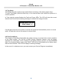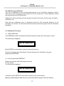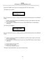
1
Raymond Coupland Ltd Priestley House Kirkby Stephen Business Park St Luke's Road Kirkby Stephen Cumbria United Kingdom CA17 4HT Tel: 0800 7720894 e-mail [email protected] USER MANUAL Instruction manual for OX-AN 16 Channel 4 - 20mA Gas Monitor v3.0 Safety Gas Monitoring Systems OX-AN 16 Channel 4 - 20mA Gas Monitor v3.0 Contents 1.0 GENERAL OPERATION ........................................................................................................................... 2 1.1 ALARM LEVEL 1 - AMBER.............................................................................................................................. 2 1.2 ALARM LEVEL 2 - RED .................................................................................................................................. 2 1.3 ISOLATING SENSORS..................................................................................................................................... 3 1.4 ALARM HOLD OFF TIME.................................................................................................................................. 3 1.5 VISUAL INDICATORS ...................................................................................................................................... 3 1.5.1 Beacons ............................................................................................................................................. 3 1.5.2 LEDs .................................................................................................................................................. 3 2.0 ACCESSING USER AND ENGINEER FUNCTIONS ............................................................................... 3 2.1 USER DISPLAY AND KEYS ............................................................................................................................. 4 2.1.1 External Inputs ................................................................................................................................... 4 2.2 USER FUNCTIONS ......................................................................................................................................... 5 2.2.1 Change Display Mode - ENTER key ................................................................................................. 5 2.2.2 Show Isolated Channels – EDIT Key................................................................................................. 5 2.2.3 Fast Cycle – UP Key .......................................................................................................................... 5 2.2.4 Slow Cycle – DOWN Key .................................................................................................................. 5 2.2.5 Channel Lock – CYCLE Key .............................................................................................................. 5 2.2.6 Reset – RESET Key .......................................................................................................................... 5 2.2.7 Mute – MUTE Key .............................................................................................................................. 6 2.3 EVENTS ....................................................................................................................................................... 6 2.3.1 Printing Events ................................................................................................................................... 6 2.4 ENGINEER FUNCTIONS .................................................................................................................................. 7 2.4.1 Engineer Menu .................................................................................................................................. 8 2.4.2 Editing Numeric Values ...................................................................................................................... 9 2.4.3 Yes/No Inputs..................................................................................................................................... 9 2.4.4 Changing Channel ............................................................................................................................. 9 2.5 MENU OPTIONS .......................................................................................................................................... 10 2.5.1 Print Setup ....................................................................................................................................... 10 2.5.2 Clear Events .................................................................................................................................... 10 2.5.4 Set Time ........................................................................................................................................... 10 2.5.5 Set Date ........................................................................................................................................... 11 2.5.6 Alarm Set Red .................................................................................................................................. 11 2.5.7 Alarm Set Amb ................................................................................................................................. 11 2.5.9 Mute Time (min) ............................................................................................................................... 12 2.5.10 Active Channels ............................................................................................................................. 12 2.5.11 Test Relay Card ............................................................................................................................. 12 2.5.12 Printer............................................................................................................................................. 13 2.5.13 Exit ................................................................................................................................................. 13 3.0 TEST MODE ............................................................................................................................................ 14 4.0 FAULT CONDITIONS ............................................................................................................................. 14 5.0 4-20MA LOOP CALIBRATION ............................................................................................................... 15 5.1 CALIBRATION PROCEDURE .......................................................................................................................... 15 5.1.1 Blank EEPROM ............................................................................................................................... 15 5.1.2 Pre-Programmed EEPROM ............................................................................................................. 15 5.2 VERIFYING CALIBRATION ............................................................................................................................. 17 5.3 SENSOR CALIBRATION ................................................................................................................................ 17 6.0 LOADING PRINTER PAPER ................................................................................................................. 18 6.0.1 Paper Setting ................................................................................................................................... 18 6.0.2 Paper Loading .................................................................................................................................. 18 6.0.3 Paper Loading during a print cycle. ................................................................................................. 19 1 OX-AN 16 Channel 4 - 20mA Gas Monitor v3.0 OX-AN Oxygen Depletion Monitor 1.0 General Operation The OX-AN Oxygen Monitoring System continuously monitors the level of Oxygen (O 2) from up to 16 individual locations. Two configurable detection levels provide audible, visual and control outputs. In a typical application, the first level alarm (amber) is set to a value which is not hazardous to health, but is a warning of a potential problem. The control output (first level relay) from the first level alarm is typically used for initiating any remedial action which may be required to reduce the O2 depletion. This alarm level is non-latching. The second level alarm (red) is typically set to an O 2 concentration which is still not immediately hazardous to health but indicates that immediate action must be taken to rectify the cause of the of O2 depletion. This action typically involves shut down procedures and the removal of personnel. 1.1 Alarm Level 1 - Amber If the level of O2 falls below the first configurable alarm level, the amber beacon is illuminated and the amber relay output is activated. The audible alarm is not activated. If the level of O2 remains below this level the amber beacon and first level relay output will remain activated. If the level of O 2 rises above this level, the system automatically deactivates the amber beacon and the amber relay output. 1.2 Alarm Level 2 - Red If the level of O2 falls below the second configurable alarm level for a period exceeding the programmable hold off time, the red beacon is illuminated and the second level relay output is activated. If a relay board if present, the channel specific relay will also be activated. Red level alarms also activate the audible alarm (sounder). The sounder can be muted using the mute button or the external mute input. Note that the red alarm is latching and hence further variations in O 2 levels will not affect the status of the main alarm relays. Red alarm status can only be removed by pressing RESET. 2 OX-AN 16 Channel 4 - 20mA Gas Monitor v3.0 1.3 Isolating Sensors Individual channels can be set not to trigger alarms by using the Isolate Sensor option from within the Engineer Menu. This feature allows specific input channels to be isolated whilst the system continues to operate. 1.4 Alarm hold off Time The Hold Off time facility allows false alarms to be reduced by continuing to sample for a specified time after the O2 level has fallen below the red alarm level to ensure that the level of O2 remains below this specified level. This facility must be used with caution since long hold off times may cause potentially hazardous situations to occur without alarm. 1.5 Visual Indicators 1.5.1 Beacons Green Beacon Amber Beacon Red Beacon O2 level above alarm level (safe) O2 level below Amber alarm level O2 level below Red alarm level 1.5.2 LEDs Fault Isolated Sensor Sounder Muted Slow Cycle Print Pending System Healthy System fault has occurred One or more sensors are isolated Sounder is muted System is in Slow Cycle mode An event is ready to print System is powered and functional 2.0 Accessing User and Engineer Functions Opening the enclosure outer door provides access to both the User and Engineer functions. User functionality is provided via the keys and does not use a menu-based system. Pressing the Engineer Switch located below the LCD provides access to the Engineer functions. Engineer functionality is controlled using a scrollable menu. Note that the inner door need not be opened to access any functionality. Mains wiring is accessible behind the inner door and hence only suitably qualified persons should have access to this area whilst the system is powered. 3 OX-AN 16 Channel 4 - 20mA Gas Monitor v3.0 2.1 User Display and Keys The User key functionality is shown below. ENTER EDIT DOW N UP PRINT CYCLE RESET MUTE In normal operation (User mode) the display will show: Channel Time OX-AN ch01 20.9% 10:21:00 01/02 O2 Level (%) Date The system will move through each channel showing the relevant O2 level. Note that for channels without sensors the O2 Level (%) field will show –NS-. This level will cause a Red alarm if the channel is active and not isolated. See section 2.5 for details of how to set a channel to inactive and/or isolated state. 2.1.1 External Inputs Two external inputs are provided via pushbuttons: System Reset – available on the main system unit. System Mute – available on main and repeat system units 4 OX-AN 16 Channel 4 - 20mA Gas Monitor v3.0 2.2 User Functions 2.2.1 Change Display Mode - ENTER key Pressing the ENTER key toggles the screen output to show the amber and red alarm levels for each channel. Channel Amber Alarm Level OX-AN ch01 20.9% A 20.0% R 19.5% O2 Level (%) Red Alarm Level 2.2.2 Show Isolated Channels – EDIT Key Pressing the EDIT key toggles between showing all channels and only active channels. Showing isolated channels increases the time between the scans of active channels and hence should not be used as the default display. 2.2.3 Fast Cycle – UP Key The UP key selects fast cycle time in which each channel is active for approximately 1 second (all channels scanned within 12 seconds). This is the default mode. 2.2.4 Slow Cycle – DOWN Key The DOWN key selects slow cycle time in which each channel is active for approximately 5 seconds (all channels scanned within 1 minute). The Slow Cycle LED is illuminated when this mode is selected. 2.2.5 Channel Lock – CYCLE Key Pressing the CYCLE key toggles between locking on a single channel and cycling between channels. The CYCLE key locks the system onto the channel currently being scanned. In this mode the locked channel number will be intermittently displayed on the LEDs. 2.2.6 Reset – RESET Key Pressing the RESET key resets the system by removing audible and visual alarm indications. The red and amber level alarm relays are deactivated by a system reset and will only be reactivated if the system identifies an alarm condition following the reset. Note: channel locking is removed following a reset. 5 OX-AN 16 Channel 4 - 20mA Gas Monitor v3.0 2.2.7 Mute – MUTE Key Pressing the MUTE key during a second level (red) alarm will mute the audible sounder. After a configurable time period the sounder will be reactivated. The visual indication and control outputs are not affected by the use of the mute facility. When the system is muted, the Mute LED is illuminated. 2.3 Events Whenever a red alarm state occurs, the system records details of the event in EEPROM. The event will be displayed on the LCD during red alarm state and will be removed when the system is reset. For each event the LCD will display: Channel Event Number Time of Event O2 Level (%) 1[01] 18.0% 10 20:54:17 12/07 Hold Off Time (sec) Date did/mm 2.3.1 Printing Events If a printer is fitted and activated, the Print Pending LED will flash to indicate that an event is due for printing. To print events press the PRINT button. Note that up to 12 events may be pending but events are printed individually, i.e. the PRINT button must be pressed for each event. 6 OX-AN 16 Channel 4 - 20mA Gas Monitor v3.0 2.4 Engineer Functions The Engineer switch is located below the LCD on the display board. Pressing the Engineer switch moves the panel into “Engineer mode”. This mode is used for configuration and provides access to the Engineer Menu. Care should be taken when using the Engineer Menu since no input verification or storage confirmation is provided. In Engineer Mode the keys are reassigned as: ENTER EXIT CHANNEL DOWN UP LEFT RIGHT On entering Engineer Mode the LCD will show: Eng Menu V3.0 16ch O2 Dep RB 7 OX-AN 16 Channel 4 - 20mA Gas Monitor v3.0 From this position, the Engineer Menu can be accessed with the UP and DOWN keys. The Engineer Menu comprises: Eng. Menu V2.0 Print Setup Clear Events Isolate Sensor Set Time Set Date Alarm Set Red Alarm Set Amb Hold Off (sec) Mute Time (min) Active Channels Test Relay Card Printer Exit 8 OX-AN 16 Channel 4 - 20mA Gas Monitor v3.0 2.4.2 Editing Numeric Values To edit numeric values press the ENTER key when the relevant menu option is displayed. The data is immediately presented for editing. Individual digits are incremented or decremented using the UP and DOWN keys. Use the LEFT and RIGHT Keys to move between digits. Save the edited data by pressing the ENTER key. Exit without saving by using the EXIT key. 2.4.3 Yes/No Inputs To edit Yes/No values press the ENTER key when the relevant menu option is displayed. The input value is then available for editing. For Yes/No entry the entered value toggles with either the UP or DOWN key. Save the edited data by pressing the ENTER key or exit without saving using the EXIT key. 2.4.4 Changing Channel For options which are channels specific, the channel can be incremented using the CHANNEL key after selecting the parameter to edit (from the menu). Note that the channel must be selected prior to editing the data. If the channel is incremented without explicitly saving an edited value, any changes will be lost. In practise this means that the editing sequence is: 1. 2. 3. 4. Select menu option Select channel Edit data Save data This sequence must be repeated for each channel. The channel is shown in the lower left of the screen. Channel ALARM Set Red [1] 19.0% 9 OX-AN 16 Channel 4 - 20mA Gas Monitor v3.0 2.5 Menu Options The following sections provide details of the individual menu options. 2.5.1 Print Setup Requires optional printer. Yes/No input for printing the setup data held in the system memory. Print Setup [N] 2.5.2 Clear Events Requires optional printer. Yes/No input for clearing any pending prints (indicated by flashing print pending LED) Print Setup [N] 2.5.3 Isolate Sensor This option provides facilities for determining whether the input from a channel should be allowed to trigger alarm states. Isolated channels can still be scanned and the values viewed on the display but no action will be taken if the O2 level falls below an alarm level. Isolate Sensor [1] [Y] Value Y or N Channel specific The Isolated Sensor LED is illuminated if one or more sensors are isolated. 2.5.4 Set Time This option allows the real time clock to be set. The input format is 24 hour. Set Time 00:00:00 No input data validation is carried out Single value for all channels 10 OX-AN 16 Channel 4 - 20mA Gas Monitor v3.0 2.5.5 Set Date This option allows the real time clock date to be set. Set Date 00/00/00 No input data validation is carried out Single value for all channels 2.5.6 Alarm Set Red This value determines the level for the activation of the red alarm relays, the sounder and the red alarm level beacons. ALARM Set Red [1] 19.0% Min Value = 00.0% Max value = 99.9% Channel specific. 2.5.7 Alarm Set Amb This value determines the level for the activation of the amber alarm relays and the amber beacons. ALARM Set Amb [1] 20.0% Min Value = 00.0% Max value = 99.9% Channel specific. 11 OX-AN 16 Channel 4 - 20mA Gas Monitor v3.0 2.5.8 Hold Off (sec) This value determines the time, in seconds, for which the level of O2 must remain below the red alarm level before the red alarm state is activated. This facility helps to reduce the incidence of alarms caused by fast changing O2 levels. Hold Off (sec) 005 Min Value = 0 Max value = 255 Single value for all channels 2.5.9 Mute Time (min) This value determines the time, in minutes, for which the sounder is muted following either a MUTE key press or an external mute. The sounder will be reactivated after the time has elapsed. Mute Time (min) 005 Min Value = 0 Max value = 255 Single value for all channels 2.5.10 Active Channels This option provides facilities for determining whether the input from a channel should be allowed to trigger alarm states. Inactive channels can still be scanned and the values viewed on the display but no action will be taken if the O2 level falls below an alarm level. Active Channels [1] [Y] Value Y or N Channel specific 2.5.11 Test Relay Card CAUTION – this menu option will activate relay outputs – ensure outputs are disconnected. Yes/No input for testing attached relay cards. Test Relay Card [Y] 12 OX-AN 16 Channel 4 - 20mA Gas Monitor v3.0 2.5.12 Printer Requires optional printer. Yes/No input for activating/deactivating the optional printer. When this option is set, the Print Pending LED will be illuminated whenever an event occurs. Printer [Y] 2.5.13 Exit Pressing the ENTER key when this option is displayed exits the Engineer mode and returns the system to User mode. Exit 13 OX-AN 16 Channel 4 - 20mA Gas Monitor v3.0 3.0 Test Mode Test Mode allows the system to be tested without activation of the alarm output relays. To enter Test Mode, press the Mute key or the external Mute input whilst the system is in normal operation. In Test mode the system flashes the Fault and Power LEDs. The LCD will show the current channel and 02 level and a warning message to indicate the change of mode. OX-AN ch01 20.9% TEST MODE !! If a red alarm does not occur within 3 minutes the system will automatically return to normal mode. A Reset also returns the system to normal mode. 4.0 Fault Conditions The integrity of the data stored within the system memory is crucial to the correct operation of the alarm system. The OX-AN 4-20mA Oxygen Depletion Monitor uses an integer checksum for verification of the contents of the serial memory and the on-chip EEPROM data. If a checksum failure occurs, the FAULT LED will be illuminated and an amber alarm state will be activated. The LCD will display a warning message. In the event of a checksum error you must contact your Service Engineer immediately. 14 OX-AN 16 Channel 4 - 20mA Gas Monitor v3.0 5.0 4-20mA Loop Calibration The unit is calibrated for loop current measurements of up to 20mA by applying a load of 3mA as the zero level and a load of 23mA as the full-scale level. These calibration values are stored within the EEPROM (IC9). Calibration involves drawing a known steady current from the loop circuitry using a suitable calibration unit. Note that the calibration menu is displayed when the CAL terminals adjacent to the processor are shorted. These terminals must remain shorted throughout the full calibration procedure. 5.1 Calibration Procedure 5.1.1 Blank EEPROM If the EEPROM is blank the board should be powered up with the CAL jumper in place. The following is displayed: Write Defaults? Press ENTER to write default values to the serial memory. Remove Cal jumper and reset board. Follow instructions for calibration using preprogrammed EEPROM. 5.1.2 Pre-Programmed EEPROM Power-up the board with CAL jumper removed. Fit CAL jumper. The following is displayed: Write Defaults? If required, press ENTER to write default values to the serial memory. Warning all edited Engineer data will be lost if you write default settings to the serial memory 15 OX-AN 16 Channel 4 - 20mA Gas Monitor v3.0 Press EXIT (PRINT button) leave the existing data within the serial memory. The display will now show: Cal Set 3mA 0000 mA=3.0 Note: the lower line is used for verifying calibration and should be ignored on un-calibrated boards. 1. Set the current being drawn by the calibration module to 3mA (read from the meter NOT the LCD display). 2. Press ENTER to calibration the zero level. Press PRINT Button to leave without calibrating. The following is displayed: Cal Set 23mA 8000 mA=23.0 Note: the lower line is used for verifying calibration and should be ignored on un-calibrated boards. 3. Set the current being drawn by the calibration module to 23mA (read from the meter NOT the LCD display). 4. Press ENTER to calibration the full scale level. Press PRINT button to leave without calibrating. 5. Remove power from the board. 6. Remove the CAL jumper 7. Remove the calibration module. The board is now calibrated for loop current measurements. 16 OX-AN 16 Channel 4 - 20mA Gas Monitor v3.0 5.2 Verifying Calibration To verify that a board is calibrated enter the calibration menu by attaching a jumper to the CAL pins. A calibrated board will show the correct mA reading for current which is drawn from the loop. Use the PRINT key to exit both calibration steps without saving. 5.3 Sensor Calibration Individual 4-20mA sensors should be calibrated using calibrated gases. 17 OX-AN 16 Channel 4 - 20mA Gas Monitor v3.0 6.0 Loading Printer Paper 6.0.1 Paper Setting NOTE Be sure to use paper rolls that meet the specifications. Do not use paper rolls that have the paper glued to the core because the printer cannot detect the paper end correctly. Take care not to get your fingers caught in the printer when installing or replacing the paper roll. 6.0.2 Paper Loading a) Make sure that the printer is not receiving data; otherwise, data may be lost. b) Open the printer door by applying your finger on both sides of the lower printer door and pull forward and downwards. – figure 1 c) Follow the same procedure for the upper door. d) With both upper and lower doors open the paper roll tub is accessible. Remove the empty paper roll spindle by pulling the spindle towards you. In some instances opening up one or both of the side spring clips may be needed to enhance spindle removal. - figure 2 e) Insert the new paper roll. Be sure to note the correct direction that the paper comes off the roll as shown. – figure 3 f) Pull out a small amount of paper and then close the upper door first, followed by the lower door. The printer should auto feed approx. 2” (50mm) of paper, this should ensure correct alignment and confirms that paper is feeding smoothly. The front panel LED should turn green and the printer is now ready to receive more print data. 18 OX-AN 16 Channel 4 - 20mA Gas Monitor v3.0 6.0.3 Paper Loading during a print cycle. If the end of paper roll takes place during printing the printer will detect that no paper is present and will send a busy signal to the host. This will interrupt printing to allow a new paper roll to be fitted. Follow the paper loading instructions in section 3.4.1. After completing the paper loading procedure and as soon as the printer auto advances the 4” (100mm) described in part f of 3.4.1 the printer will release the busy status line and data will resume being received by the printer, printing will commence automatically. 19