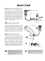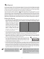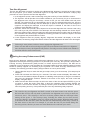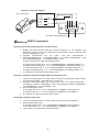
1
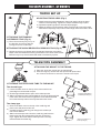
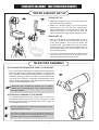
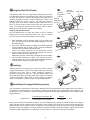
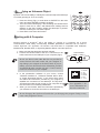
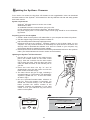
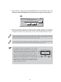
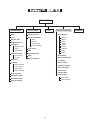
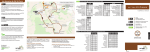
AZ GOTO TELESCOPES ESC SET UP ENT ER TO UR 1 RA 2 M UTIL C NE 7 ITY NG 5 PLA TE 3 4 6 T OB IC JEC 8 T US 9 ER ID 0 GT020609V3-03.05 TABLE OF CONTENTS TELESCOPE ASSEMBLY - GT MOUNTS 3 TELESCOPE ASSEMBLY - MULTIFUNCTION MOUNTS 4 USING THE RED DOT FINDER 5 FOCUSING 5 CALCULATING THE MAGNIFICATION (POWER) 5 THE SYNSCAN AZ 6 TM INTRODUCTION TO THE SYNSCAN AZ 6 POWERING THE SYNSCAN AZ 6 SYNSCAN AZ HAND CONTROL 6 TM TM TM HAND CONTROL OPERATION 8 INITIAL SETUP 8 STAR ALIGNMENT 9 POINTING ACCURACY ENHANCEMENT (PAE) OBJECT CATALOG 10 11 OBJECT DATABASE IN THE SYNSCAN AZ 11 SELECTING AN OBJECT 11 TM OTHER FEATURES 12 UTILITY FUNCTIONS 12 SETUP FUNCTIONS 12 USING THE USER DEFINED DATABASE 12 IDENTIFYING AN UNKNOWN OBJECT 14 LINKING WITH A COMPUTER 14 UPDATING THE SYNSCAN AZ FIRMWARE 15 TM SYNSCAN AZ MENU TREE 17 TECHNICAL SPECIFICATIONS 18 TM APPENDIX A - RS-232 CONNECTION I APPENDIX B - STANDARD TIME ZONES OF THE WORLD II BEFORE YOU BEGIN This instruction manual is applicable to all the models listed on the cover. Follow the instructions for your specific model in the manual. Read the entire instructions carefully before beginning. Your telescope should be assembled during daylight hours. Choose a large, open area to work to allow room for all parts to be unpacked. TELESCOPE ASSEMBLY - GT MOUNTS TRIPOD SET UP Fig.1 ADJUSTING TRIPOD LEGS (Fig.1) 1) Slowly loosen the height adjustment clamp and gently pull out the lower section of each tripod leg. Tighten the clamps to hold the legs in place. 2) Spread the tripod legs apart to stand the tripod upright. 3) Adjust the height of each tripod leg until the tripod head is properly leveled. Note that the tripod legs may not be at same length when the mount is level. Fig.2 ATTACHING THE TRIANGLE ACCESSORY TRAY (Fig. 2) 1) Place the accessory tray on top of the bracket, and secure with the locking knob from underneath. Fig.3 ATTACHING THE QUICK-RELEASE ACCESSORY TRAY (Fig. 3) 1) Hold the accessory tray directly above the bracket. Rotate the tray until the shape of the hole matches the locking mechanism in the center of the bracket. Place the tray on top of the bracket and rotate to lock the tray in place. TELESCOPE ASSEMBLY ATTACHING THE MOUNT TO THE TRIPOD Fig.4 1) Place the single arm mount into the tripod head. 2) Push the large cup underneath the tripod head upward and turn counter-clock wise to secure the mount to the tripod. ATTACHING THE TELESCOPE TUBE TO THE MOUNT The dovetail type 1) Loosen the black screw on the top of the mount until it is not protruding from the dovetail accepter. 2) Find the approximate balance point on the telescope tube. 3) Slide in the telescope tube until the balance point of the telescope falls in the center of the mount head. Tighten the screw until the dovetail bar on the telescope tube is securely fastened on the mount. (Diagram applicable to all telescope designs.) Fig.5 The clamp type 1) Remove the black screw on the top of the cradle ring and place it at a safe place for later use. 2) Carefully open the cradle ring just enough so the telescope tube can be slided in. 3) Slide in the telescope tube. Close the cradle ring and insert the black screw from the opposite side of the arm as shown in Fig.4. Tighten the screw until the telescope tube is securely fastened inside the cradle ring. 3 (Diagram applicable to all telescope designs.) TELESCOPE ASSEMBLY - MULTIFUNCTION MOUNTS TRIPOD & MOUNT SET UP Fig.6 Fig.7 TRIPOD SET UP 1. Remove the tripod from the box and spread the legs apart until fully extended. 2. Adjust the desired height of the tripod before attaching the fork arm and your optical tube. Minor adjustments can be made later. Loosen the locking mechanisms on each leg and slide the legs to the desired height and then retighten them. MOUNT SET UP 1. Next you will attach your Multi-function mount to the tripod. Locate the 3/8" threaded bolt in the top of the tripod platform. Then, find the mating 3/8" threaded hole underneath the Fork Arm Base. Thread the 3/8" bolt of the tripod platform into the 3/8" threaded hole in the fork arm base until it is good and tight (Fig.6). 2. Locate the 1/4x20 Mounting Platform. Slide it down the slot on the Fork Arm as in dicated in Fig.7. Secure by tightening the thumb screws. TELESCOPE ASSEMBLY ATTACHING THE TELESCOPE TUBE TO THE MOUNT 1. If you are using the telescope for tracking astronomical objects, attach the optical tube to the Mounting Platform so that the Fork Arm is located on the right hand side (Fig.8). If the telescope is installed incorrectly you will not be able to use the latitude scale on the top of the Fork Arm. Thread the 1/4x20 Mounting Screw into the 1/4x20 tripod adapter of the optical tube and make sure it is tight. Do not overtighten the screw. Telescopes with a dovetail bar attached can be installed directly onto the Multi-function mount without using the Mounting Platform. ATTACHING A CAMERA TO THE MOUNT 1. For general terrestrial use, the camera can be secured on the Mounting Platform any way you wish. Thread the 1/4x20 Mounting Screw into the camera and make sure it is tight. Do not overtighten the screw. Do NOT overtighten the 1/4x20 Mounting Screw or it may cause damage to the screw. You must be careful not to use an optical tube that is too heavy or too big as the motor assembly will not be able to operate properly and you may damage the mount. 4 Fig.8 Using the Red Dot Finder Fig.a The Red Dot Finder is a zero magnification pointing tool that uses a coated glass window to superimpose the image of a small red dot onto the night sky. The Red Dot Finder is equipped with a variable brightness control, azimuth adjustment control, and altitude adjustment control (Fig.a). The Red Dot Finder is powered by a 3-volt lithium battery located underneath at the front. To use the Finder, simply look through the sight tube and move your telescope until the red dot merges with the object. Make sure to keep both eyes open when sighting. ON/OFF Brightness Control Azimuth adjustment control Sight Tube Altitude Adjustment Control Battery cover Aligning the Red Dot Finder Like all finderscopes, the Red Dot Finder must be properly aligned with the main telescope before use. This is a simple process using the azimuth and altitude control knobs. Fig.b 1. Open the battery cover by pulling it down (you can gently pry at the 2 small slots) and remove the plastic shipping cover over the battery (Fig.b). 2. Turn on the Red Dot Finder by rotating the variable brightness control clockwise until you hear a "click". Continue rotating the control knob to increase the brightness level. Insert a low power eyepiece into the telescope's focuser. 3. Locate a bright object and position the telescope so that the object is in the centre of the field of view. With both eyes open, look through the sight tube at the object. 4. If the red dot overlaps the object, your Red Dot Finder is perfectly aligned. If not, turn its azimuth and altitude adjustment controls until the red dot is merged with the object. Plastic shipping cover Fig.c Focusing Slowly turn the focus knobs (Fig.c), one way or the other, until the image in the eyepiece is sharp. The image usually has to be finely refocused over time, due to small variations caused by temperature changes, flexures, etc. This often happens with short focal ratio telescopes, particularly when they haven't yet reached outside temperature. Refocusing is almost always necessary when you change an eyepiece or add or remove a Barlow lens. Calculating the magnification (power) The magnification produced by a telescope is determined by the focal length of the eyepiece that is used with it. To determine a magnification for your telescope, divide its focal length by the focal length of the eyepieces you are going to use. For example, a 10mm focal length eyepiece will give 80X magnification with an 800mm focal length telescope. magnification = 800mm Focal length of the telescope Focal length of the eyepiece = 10mm = 80X When you are looking at astronomical objects, you are looking through a column of air that reaches to the edge of space and that column seldom stays still. Similarly, when viewing over land you are often looking through heat waves radiating from the ground, house, buildings, etc. Your telescope may be able to give very high magnification but what you end up magnifying is all the turbulence between the telescope and the subject. A good rule of thumb is that the usable magnification of a telescope is about 2X per mm of aperture under good conditions. 5 AZ I ntroduction to the SynScan AZ TM The SynScan AZ is a precision-engineered instrument that will allow you to easily find and enjoy viewing night sky treasures, such as planets, nebulea, star clusters, galaxies and much more. The hand control allows you to point your telescope at a specific object or even tour the skies at the touch of a button. The user friendly menu system allows automatic slewing to over 42,900 objects. Even an inexperienced astronomer can master its variety of features in a few observing sessions. Below is a brief description of the individual components of the SynScan AZ hand controller. Fig.d-2 TM SETUP ESC TOUR 1 M 4 PLANET 7 RATE 2 NGC 5 OBJECT 8 Multi-Function Mount ENTER EVENT 3 IC 6 USER 9 SNAP ID 0 IN DC12V OUT Fig.d-2 HC ON/OFF AUX TM Powering the SynScan TM power supply power switch AZ The SynScan AZ should be powered by 11-15V DC power supply (tip-positive) capable of producing continuous current of minimum 1 amps. Correctly plug the power cord into the 12V DC outlet on the the mount (See Fig.d-1 and d-2 for Multi-function telescopes and Fig.e-1 and e-2 for AutoTracking telescopes). For Multi-function telescopes, flip the Power Switch to the "on" position to turn on the power. TM S ynScan TM AutoTracking Mount SETUP ESC ENTER Fig.e-1 TOUR RATE M NGC 1 4 PLANET 7 2 5 OBJECT 8 EVENT 3 IC 6 USER 9 ID 0 AZ Hand Control The SynScan AZ hand control cable has a RJ-45 with 8 connecting pins on one end and a RJ-12 with 6 connecting pins on the other end. Plug the RJ-45 end into the hand control (Fig.c) and the other end into the outlet on the mount (Fig.b). On the bottom of the hand control, the middle port is used for RS-232 communications between the SynScan AZ and a computer or other devices. (See “Linking with a Computer” for details.) The DC power port allows independent use of the SynScan AZ hand control for users who wish to browse the database or update the firmware without connecting to the telescope (Fig.f). TM Fig.e-2 power supply TM TM Fig.f RJ-45 The DC power port on the hand control is for hand control stand-alone applications only. For telescope applicaions, use the 12V DC outlet on the mount. RJ-12 DC power port To connect the SynScan AZ to a PC, use only the RS-232 cable provided with the mount. TM 6 This section provides a step-by-step procedure on how to operate your SynScan AZ hand control. TM I nitial Setup 1. Make sure the mount is level to the ground. 2. Point the telescope roughly to one or a group of visible bright stars in the sky. 3. Connect the hand control to the mount with the provided cable. For AutoTracking telescopes, plug the DC 12 volt power into the outlet of the mount to turn on the power. For Multi-function telescopes, simply flip the power switch to the “on” position. 4. The initial screen displayed on the hand control is the Version Screen. You will hear a long beep indicating that the hand control is properly connected to the mount. The directional keys are now activated. You can now move the telescope using the directional keys on the hand control. The default speed rate at this point is Rate 9. Press ENTER to proceed to the next Initial Setup step. If the hand control is not properly connected to the mount, the screen will display “No link to M.C. Stand-alone mode”. If you wish to use the hand control to control the mount, unplug the connection cable and try again. 5. The hand control will display a warning concerning pointing the telescope at the sun without proper equipment. If you have read the message already, pressing ENTER will bypass the message and skip to the next step. The hand control's red light will become dimmer and the backlight of the key pads will turn off if idle for 30 seconds. Pressing any key turns it back on. 6. Enter the telescope's current latitudinal and longitudinal position using the numeric keypad. First enter the longitudinal coordinate, followed by the latitudinal coordinate. Use the scroll keys to choose between W or E, and N or S. Pressing the left or right directional keys will move the cursor to the previous or next number. Press ENTER to confirm. The format you enter should look like this: 123 04’ W 49 09’N. 7. Enter your current time zone in hours and minutes (see Appendix C), using the scroll keys and numeric key pad (+ for East, - for West). Press ENTER to confirm. The format you enter should look like this if you are in Pacific Standard Time (PST): -08:00. 8. Enter the date in the following format mm/dd/yyyy using the numeric keypad. Press ENTER to confirm. 9. Enter your current local time using the 24 hr time mode (e.g. 2:00PM=14:00). Press ENTER to view the time you just entered. If it is incorrect, press ESC to go back to the previous screen. If correct, press ENTER again to proceed to the daylight saving setting. 10. After entering the current time, the SynScan AZ will prompt "DAYLIGHT SAVING?". Use the scroll keys to make the selection and press ENTER to confirm. After setting the daylight saving, SynScan will display "Begin alignment?". Press "1" or ENTER to start the alignment procedure. Press "2" or ESC to skip the alignment and exit to the Main Menu. TM TM If a mistake was entered into the SynScan AZ hand control, press the ESC key to go back to the previous menu, and press ENTER to start again. TM 8 Star Alignment In order for the SynScan AZ to correctly point to objects in the sky, it must first be aligned to two to three known positions (stars) in the sky. As the Earth rotates on its axis every 24 hours, astronomical objects appear to move through the sky following an arc. With the supplied information, the telescope can replicate a model of the sky and the movements of astronomical objects. Star alignment can be done anytime during the observing session by choosing Alignment under Setup Mode, in the Main Menu. TM There are two ways to align the SynScan AZ Brightest Star alignment and 2-Star alignment. If you are using the SynScan AZ for the first time, and you are not familiar with the celestial object in the sky, we recommend that you begin with the Brightest Alignment. The Brightest Star alignment will prompt and help you find the brightest star of a specific direction in the sky at your current site. It is convenient for user to identify the brightest star in the sky. Before performing the alignment method, make sure that your finderscope is well aligned with the telescope tube. See the next page for tips on how to choose the alignment stars. Below describes a step-by-step procedure on how to perform the Brightest Star Alignment: TM TM Brightest Star Alignment 1. In the alignment screen, select Brightest-Star Align using the scroll keys. Press ENTER to confirm. The hand control will prompt "Select Region:" for you to select one of the eight directional divisions in azimuth angle from the north, northeast, east, southeast to northwest etc. Each division covers 90-degree span in azimuth. That means if you select the Directional division Span range in azimuth northeast sky, the division will cover from The northern sky 315 ° ~ 45 ° 0 degree to 90 degrees in azimuth, The northeast sky 0 ° ~ 90 ° where North equals to 0 or 360 degree in azimuth angle, East equals to 90 degree The eastern sky 45 ° ~ 135 ° in azimuth angle, South equals to 180 The southeast sky 90 ° ~ 180 ° degree in azimuth angle, and West The southern sky 135 ° ~ 225 ° equals to 270 degree in azimuth angle. The southwest sky 180 ° ~ 270 ° The table on the right is the range of The western sky 225 ° ~ 315 ° the eight directional divisions. The northwest sky 270 ° ~ 360 ° 2. Once the directional division has been selected, the hand control will calculate and generate a list of the stars located within this region that are brighter than 1.5 in magnitudes. The stars and planets below 10 degrees, higher than 75 degrees in elevation or fainter than 1.4 in magnitudes will be filtered out. 3. The name and magnitude of the alignment star will be displayed on the first line of the LCD. The approximate position will be prompted on the second line. For example, if Arcturus is prompt as alignment star, its magnitude is 0.0 and location is at 88.1 degree east and 24.1 degree above the horizon. You will see the LCD display as shown in Fig.k. Fig.k 4. For the first alignment star, the mount will not slew to the star automatically. Use the directional buttons to manually slew the telescope to point 1. Arcturus 0.0 to the object in the finder and then center it in the eyepiece. You may E 88.1° 24.1° change the slewing speed by pressing the RATE button, and then choose a number between 0 (slowest) - 9 (fastest). 5. Once the star has been centered in the eyepiece, if it is a planet the hand control will prompt you to reselect a star from the list as the first alignment star. Otherwise the hand control will prompt a list of objects for you to choose as the second alignment star. Select an object from the list. The hand control will command the mount to slew the telescope to point to the object. Center the object in the eyepiece again. If both alignment stars are properly aligned, "Alignment Successful" will display on the LCD. Otherwise, the warning "Alignment Failed" will show and the alignment will have to be done again. You may exit the alignment procedure by pressing the ESC key anytime during the procedure. AZ will beep once when it has finished slewing to an object. Do not try to adjust the telescope before you hear the beep. SynScan AZ will only respond to the ESC key while slewing. SynScan The slewing speed can be adjusted by pressing on the RATE button. Then choose a number between 0 (slowest) - 9 (fastest). TM TM 9 Two-Star Alignment The two star alignment procedure is similar to the Brightest Star alignment, except that the hand control will not prompt for you to select a directional region for a bright star. Below describes a step-by-step procedure on how to perform the Two-Star Alignment: 1. In the alignment screen, select 2-Star Align using the scroll keys. Press ENTER to confirm. 2. The SynScan AZ will provide a list of stars available in your current sky for you to choose as the first alignment star. Using the scroll keys, choose a star you are most familiar with and press ENTER. The telescope will not automatically slew to the first selected alignment star. Use the directional buttons to manually slew the telescope to point to the object. Now look through the eyepiece and adjust the telescope so that the object is centered in the field of view of the eyepiece. Press ENTER to confirm. 3. SynScan AZ will now provide a list of objects for the second alignment star. Choose a star using the scroll keys and press ENTER. The telescope will start slewing towards the chosen object. When the slewing stops, adjust the telescope with the directional keys until the star is centered on the crosshairs in the finder scope. Repeat the centering procedure to center the object in the field of the eyepiece and press ENTER to confirm. 4. If both alignment stars are properly aligned, "Alignment Successful" will display on the LCD. Otherwise, the warning "Alignment Failed" will show and the alignment will have to be done again. TM TM Following is some pointers on how to choose appropriate alignment stars: Select two stars that are at least 60 degrees apart. The more distance between the two alignment stars, the better accuracy the alignment will produce. Choosing two stars with the same altitude in elevation will also create a better result. Pointing Accuracy Enhancement (PAE) Both the star alignment methods provide alignment adequate for any visual observing purpose. For applications that require extra high precision in a particular part of the sky, the SynScan AZ provides a Pointing Accuracy Enhancement (PAE) function to further improve the accuracy. The PAE can be performed in up to 85 zones to cover the whole sky. The area(s) where the chosen alignment star(s) is located should be already mapped out accurately by the SynScan AZ. Further accuracy enhancement is not necessary. The following provides a step-by-step procedure on how to perform PAE: TM TM 1. Use the direction keys to center the last go-to object, then go to the next step. (This step may be skipped.) 2. Press and hold down the ESC key for 2 seconds. The hand control will display "Re-center" and the name of the reference object will appear in a blinking mode (3 times). If the go-to command is sent from the planetarium software, instead of the name of the object, the hand control will display "Last goto object". 3. Make sure that the reference object is still in the center of the view and press ENTER. If you do not wish to record the result, press ESC to abort the operation. After pressing ENTER, the SynScan will record the amount of pointing inaccuracy and recalculate the model of the sky. Now the pointing accuracy of this particular part of the sky should be greatly improved. TM The result for the star alignments and PAE is stored in the hand control even after the power has been shut off. You will only need to perform the star alignment once as long as these two criteria are met: 1. The telescope is moved to its home position (Park the telescope) before turning off the power. 2. The telescope setup, including the mount, has not been moved. Accessory change is acceptable as long as it is done with great caution. When the hand control is turned on for the next time, make sure that the time entered during initial setup is based on the same source as last time. For example, if you enter the time on your watch during this observing session, the time you enter next time should also be read from your watch. 10 O bject database in the SynScan TM AZ The SynScan AZ comes with a vast database with over 42,900 objects coordinates and information all available in the palm of your hand. The database contains the following catalogs: TM Solar System - The other 8 planets of our solar system, plus the Moon. Named Star - A list of 212 best known stars from the SynScan AZ database. *NGC - 7,840 of the brightest deep sky objects from the Revised New General Catalog. IC - 5,386 of standard stars and deep sky objects from the Indexed Catalog. Messier - Complete list of 110 Messier objects. Caldwell - Complete list of 109 Caldwell objects. Double Stars - Includes 55 well-known double stars. Variable Stars - Includes 20 will-known variable stars. SAO - Includes 29,523 stars. TM S electing an Object Once the telescope has been aligned. You can now access and view the 42,900 different objects in the SynScan database. There are three methods of selecting a celestial object to view: TM (Fig.l) TOUR - Takes you on a preset tour across your current sky. It will automatically choose from the database the brightest and most beautiful deep-sky objects for your viewing pleasure. Use the down scroll key to view through the deep sky objects. Choose the desired object by pressing ENTER. It will show the coordinate of the chosen object. Pressing ENTER once more will cause the telescope to slew to the object. M, NGC, IC - These shortcut keys give you access to the most popular celestial catalogues to date. Each Catalog has a set number of objects to choose from. Use the numeric keys to select an object by entering its number. Pressing ENTER will display its coordinate. Primary information such as size, magnitude, and constellation are obtained by pressing the scroll keys. Pressing ENTER once more will cause the telescope to slew to the object. Fig.l Fig.m PLANET - This shortcut key takes you straight to the Planets sub menu in the database. Use the scroll keys to scroll through the list of planets in our solar system. Press ENTER to view its coordinates, and ENTER once more to slew to the planet. USER - This will take you to the database that you have defined for yourself. You can enter a new location or recall the objects that have been previously saved (see Using the User Defined Database). The OBJECT key takes you to the Objects Catalogue, where you have complete access to over 42,900 celestial objects in the (Fig.m) database. (See Object database in the SynScan AZ and the menu tree.) Fig.n TM In the Main Menu, scroll down to OBJECT CATALOG and press ENTER. Similar to the OBJECT key, this gives you the complete (Fig.n) access to all 42,900 celestial objects in the database. (See Object database in the SynScan AZ and the menu tree.) TM 11 OBJECT CATALOG U tility Functions Utility Functions are useful tools that provide simple, one-step processes to your SynScan AZ. Show Position - This displays the coordinates of the location where the telescope is currently pointed. Show Information - Under this submenu, you may check local time, local sidereal time, hardware, firmware and database version of the SynScan hand control. If the hand control is connected to the mount, this menu will also display the firmware of motor control board. Park Scope - This moves the telescope to the Home position or parks the telescope at the current or previously stored parking position. PAE - Pointing Accuracy Enhancement function. Clear PAE data - This allows you to clear all PAE data. GPS - This allows you to obtain information from the SynScan GPS receiver. TM S etup Functions The Setup functions allow you to change any system variable or information regarding location, time, date, and alignment configurations. To access the Setup Functions, either press SETUP key on the key pad or scroll to SETUP under menu option using the scroll keys. Below lists the different types of functions available to you, and their purposes. Date - Allows you to change the date entered at the initial setup. Time - Allows you to change the current time. Observing site - Allows you to change the current location. Daylight Savings - Allows you to change the Daylight Savings option. Alignment - Allows you to perform the star alignment. Alignment Stars Auto Select - When this option is chosen, the hand control will filter out the star not suitable for star alignment. Sort by - This allows the hand control to generate a list of alignment stars and display them alphabetically or by their magnitude. Backlash - This feature allows you to insert a value for each axis to compensate for its backlash. For better pointing accuracy, it is important that the backlash value is set to be equal or greater than the real amount of backlash between the gears. The default setting of the backlash is 0 d 00' 00" (0 degree, 0 arcmin. and 0 arcsec.). Use the numeric keys to enter the desired value and press the RIGHT directional key to move the cursor to the next digit. First set the value for R.A. Press ENTER to proceed to Dec. Tracking Sid. Rate: This activates tracking in Sidereal rate (Dual Axes Tracking). Lunar Rate: This activates tracking in Lunar rate (Dual Axes Tracking). Solar Rate: This activates tracking in Solar rate (Dual Axes Tracking). Stop Tracking: This stops the tracking instantly. Auto Tracking - This feature allows for quick tracking of a celestial object while the hand control displays the coordinates the telescope is curretnly pointed at. If the star alignment procedure has already been performed, you can activate the AutoTracking mode any time. If not, make sure that the location and time have been properly entered. Before choosing the Auto Tracking mode, position the telescope so that the tube is level and pointed to the North. Set Slew Limits - Allows you to set the slewing limits of the mount on altitude axis. Setting the slew limit prevents the optical tube from colliding with mount. The slew limit range is dependent on the mount and the optical tube installed on the mount. Handset Setting - This submenu allows adjustments of the brightness of the LCD backlit, the darkness of the LCD lettering, the brightness of the LED backlit and the beeper volume. Press the RIGHT or LEFT directional key to increase or decrease the value. Factory Setting - This submenu allows you to reset the hand control to its default setting. 12 U sing the User Defined Database Fig.o SynScan AZ allows you to save up to 25 objects in the user defined database. TM Saving an object to the database 1. In the Main Menu, use the scroll keys to scroll down the list until you find Object Catalog. Press ENTER. 2. Select User Defined in the Object Catalog scroll list and press ENTER. The User Defined menu can also be accessed by pressing the quick reference hot key "USER" (number 9). Fig.o 3. The first available selection in the Object Catalog is Recall Object. This is where you select previously-saved Fig.p objects to view. Use the scroll keys to scroll down to "Edit Objects" and press ENTER. 4. The SynScan AZ stores the user-defined objects in two Enter RA-DEC: formats-R.A/Dec and Alt/Az. Press 1 for the R.A/Dec. 22h46.1m +90 00 format and 2 for the Alt-Azimuth format. 5. By default the SynScan will display the R.A./Dec or Alt/Az coordinates where the telescope is currently pointed. In the case of R.A/Dec format, the coordinate readout will be similar to this: "22h46.1m +90 00'" (Fig.p) which means 22 hours and 46.1 minutes in R.A. and "+90 00'" in Dec. Change the coordinates using the numeric keypad and scroll keys. Use the RIGHT or LEFT directional keys to move the cursor to the next or previous digit. Press ENTER to save. TM TM If the R.A./Dec coordinate entered does not exist, the SynScan AZ hand control will not respond when the ENTER key is pressed. Check the entry for mistake and re-enter the correct coordinate. TM 6. To store an object/location in Alt/Az format, first point the telescope to the desired location to obtain the Alt/Az value, then press ENTER to save. 7. After the coordinates have been saved, the SynScan AZ will display an User Object number as shown in Fig.q. Use the scroll keys to change to the number you wish to represent the coordinates and press ENTER. 8. The SynScan AZ will display "View Object?" and the User Object number you just entered. Press ENTER to go to the object or ESC to return to the Input Coordinate menu. Fig.q TM Save? <ENTER> User obj. # 03 TM The User Object number displayed may not be a vacant one. If you are unsure which numbers are vacant, it is recommended that you first check for the available numbers by recalling the saved user objects. Recalling an user defined object 1. See Step 1-4 of "Saving an object to the database" for details on how to access to the User Defined menu. Select Recall Object and press ENTER. 2. Use the scroll keys to browse through the User Object number until the number representing the object you wish to view is present. Press ENTER to show its coordinate. Press ENTER again to slew to the object. The hand control will not respond if a vacant User Object number is selected. Use the scroll keys to choose another number and try again. If the recalled object is below horizon, the SynScan AZ hand control will display "Below Horizon !!" and automatically return to the Recall Object menu. TM 13 I dentifying an Unknown Object Fig.r SynScan AZ has the ability to identify the unknown object the telescope is currently pointing at. To do so, simply: TM 1. Press the ID key (Fig.r) or scroll down to IDENTIFY in the main menu and press ENTER to identify the object. 2. The hand control will display a list containing the closest known object in each M, IC, NGC, and Named Star catalogs and its distance to the exact location where the telescope is pointed. Use the scroll keys to view these objects. 3. Press ESC to exit from this function. L inking with A Computer Another feature of SynScan AZ is the ability to connect to a computer via a serial communication cable. Many commercially available planetarium softwares can be used to control SynScan AZ. SynScan AZ Version 3.00 and later is compatible with Celestron NexStar 5i/8i, NexStar GPS, or Synta SkyWatcher Mount command protocol. TM TM TM 1. Make sure that the telescope has been aligned. 2. Connect the RS-232 cable to the RJ-11 connector on the hand control and to the COM-port of your computer (Fig.s). Do not use RS-232 cable other than the one provided to connect between the hand control and your computer. It may damage your computer or the hand control. If you are making your own cable based on the information provided in Appendix B, make sure that only pin 2, 3 and 5 connect to the com connector on your computer. Fig.s Hand Control RJ- 11 RJ-11 Pin-outs 3. In the planetarium software of your choice, choose "Celestron NexStar 5i", "Celestron NexStar 8/9/11 GPS", or “Synta Skywatcher Mount” in the driver setup menu and follow the instructions provided by your program to establish the connection to the telescope. The SynScan AZ should be under the full control of your computer once the connection is successfully established. 4. When you are finished, follow the instructions provided by your software to close the connection to the telescope. 654321 1= 2= 3= 4= 5= 6= EXPD+ TD GND EXPDRD +12V TM See Appendix C for more information on RS-232 connection. Do not disengage the SynScan AZ unit before you disengage the program. Doing so may cause some programs to freeze. 14 U pdating the SynScan TM Firmware From version 3.0 onward, the SynScan AZ firmware is user upgradeable. Users can download the latest version of the SynScan AZ firmware from the Sky-Watcher web site and easily update their hand controls. TM TM System requirements SynScan AZ Hand Control of version 3.0.or later. Windows95 or later An available RS-232C communication port on the PC. PC link cable that comes with the SynScan AZ hand control. DC power supply with 7.5~15V/100mA output. Power plug should be 2.1mm diameter, tip positive. TM TM Preparing your PC for the update 1. Create a folder for all SynScan AZ related files on your computer and name it SynScan. 2. Visit the Support Page of the Sky-Watcher website at: http://www.SkywatcherTelescope.net/Support.html. 3. Download and save the SynScan Firmware Loader to the SynScan folder on your computer. You may create a shortcut on the desktop for quick access in the future. You will only need to download this software once. Once it is saved on your computer, only the firmware data file is needed for future updates. 4. Download and save the firmware data file named SynScanVXXXXAZ.ssf to the SynScan folder. (The XXXX indicates the version number of the firmware.) TM TM Updating the SynScan AZ Hand Control TM 1. Plug the RJ-11 end of the PC link cable into the jack in the middle socket on the hand control (Fig.c). Push the connector into the hand control until it clicks into place. Plug the other end of the cable, the DB9 connector, to the RS-232 port on your PC. 2. Press and hold down the key "0" and "8" simutaniously, then plug the power cord into the hand control, as shown in Fig.t. 3. The hand control will give a beep, indicating a successful start up. The SynScan AZ will display: "SynScan Update Ver. x.x" on the LCD screen, as seen in Fig.u. 4. Run the SynScanFirmwareLoader software on your PC. Once the program is launched, you should see a window as Fig.v. The "HC.Version" button provides the version number of the hardware, firmware and database of your hand control. It is for your reference only. You will not need it for the update. Fig.t SETUP ESC TOUR RATE M NGC 1 4 PLANET 7 2 5 OBJECT 8 ENTER UTILITY 3 IC 6 USER 9 TM ID 0 TM Fig.v Fig.u SynScan Firmware Loader SynScan Firmware Loader 1.0 SynScan Update Ver. 1.3 Firmware File: ESC SETUP Browse Update ENTER 15 HC. Version 5. Click "Browse" to select the SynScanVXXXXAZ.ssf file in the SynScan folder. Click "Update" to start downloading the new firmware into your SynScan AZ hand control. You will see the status of the update below the "Update" and "HC. Version" buttons (Fig.w). TM Fig.w SynScan Firmware Loader SynScan Firmware Loader 1.0 Firmware File: Browse Update HC. Version 78% 6. When the download is complete, the status will show "Update Complete". The SynScan hand control is now updated to the newest firmware. Generally it takes about 30 seconds to update the firmware. It may take longer if you are using an USB-to-RS232 converter. TM If the error message "Can not connect to a SynScan hand control" is shown, check the cable connection and the PC link cable itself. Make sure it is all in good working condition. Close all applications that may be occupying the RS-232 port and try again. If you receive the error message "Firmware update failed…", reset the hand control by removing the power plug and then re-connecting it. Repeat the update procedure. By default, the data communication rate between SynScan hand control and the PC is set to be 115kbps. The RS-232C port on some PCs may not support such high rate. If the update process fails after a few tries, you can reduce the rate by pressing the "SETUP" key once or twice on the hand control after the power supply is plugged in. This will reduce the data rate to 9.6 kbps . The LCD screen will show the word "Lo" in the lower right hand corner to indicate that it is now in low communication rate. The steps for updating the firmware remain the same except that now it takes longer to complete (about 240 seconds). TM 16 SynScan Update Ver. 1.3 ESC SETUP ENTER AZ MAIN MENU SETUP MODE UTILITY FUNC. Date Show Position Time Show Information Observ. Site Alignment Alignment Stars Auto Select Sort By Backlash OBJECT CATALOG Solar System Mercury Venus Mars Jupiter Saturn Uranus Neptune Pluto Moon Time Version Temperature Power Voltage Daylight Saving Brightest Star Align. 2-Star Align TOUR Park Scope PAE Clear PAE Data GPS Named Star PC Direct Mode Messier Catalogue IC Catalog Tracking NGC Catalog Sidereal Rate Lunar Rate Solar Rate Stop Tracking Caldwell Catalog SAO Catalogue Double Star Variable Star Auto Tracking User Defined Set Slew Limits Edit Object Recall Object Handset Setting Factory Setting 17 IDENTIFY SynScan AZ SPECIFICATIONS TM Power Supply: Motor type and resolution: Slew speeds: Tracking Rates: Tracking Mode: Alignment Method: Database: Pointing Accuracy: 11 to 15 V DC 1Amp (Tip positive) DC Servo Motors Resolution: GT mount: 1.3746 arc sec Multifunction mount: 942,803 steps/rev Rate 0 = 1.0X Rate 1 = 2.0X Rate 2 = 8X Rate 3 = 16X Rate 4 = 32X Rate 5 = 200X Rate 6 = 400X Rate 7 = 600X Rate 8 = 800X Rate 9 = 1000X Sidereal, Lunar, Solar Dual Axes Tracking Brightest-Star Alignment, Two-Star Alignment 25 user defined objects. Complete M, NGC, and IC and SAO catalogues, total 42,900 objects Up to 10 arc min 18 The SynScan AZ telescopes are designed to receive control commands sent from a computer via the RS-232 port and RS-232 cable. Once connected, the SynScan AZ can be controlled by most popular planetarium software program. The SynScan AZ will communicate with the personal computer at 9600 bits/sec, no parity and stop bit. All angles are communicated with 16 bit angle and communicated using ASCII hexadecimal. TM TM TM Description PC Command ASCII Hand Control Response Echo Kx X# Goto Azm-Alt B12AB, 4000 # Goto Ra-Dec R34B, 12CE # Get Azm-Alt Z 12AB, 4000# Get RA-Dec Cancel Goto Is Goto in Progress E M L 34AB, 12CE# # 0# or 1# Is Alignment Complete J 0# or 1# HC version Stop/Start Tracking 22 # 32-bit goto RA-Dec 32-bit get RA-Dec V Tx x= 0 (Tracking off) x= 1 (Alt-Az on) x= 2 (EQ-N) x= 3 (EQ-S) r34AB0500,12CE0500 e 32-bit goto Azm-Alt 32-bit get Azm-Alt b34AB0500,12CE0500 z # 34AB0500, 12CE0500# # 34AB0500, 12CE0500# I Notes Useful to check communication 10 characters sent. B=Command, 12AB=Azm, comma, 4000=Alt. If command conflicts with slew limits, there will be no action. Scope must be aligned. If command conflicts with slew limits, there will be no action. 10 characters returned, 12AB=Azm, comma, 4000=Alt, # Scope must be aligned. 0=No, 1=Yes: “0” is ASCII character zero 0=No, 1=Yes Two bytes representing V2.2 Alt-Az tracking requires alignment The last two characters will always be zero. The last two characters will always be zero. Physical Connection Diagram RJ-11 Connector 1= NC 2= RD 3= GND 4= NC 5= TD 6= NC 1 2 3 4 5 RD = 2 GND = 5 1 2 3 5 TD = 3 6 The Back of the DB9 Pinout 6 9 A dditional RS232 Commands Sending a track rate through RS232 to the hand control 1. Multiply the desired tracking rate (arc seconds /second) by 4. For example: if the desired track rate is 120 arc seconds/second (proximately 8 times of sidereal rate), then the TRACKRATE = 480. 2. Separate TRACKRATE into two bytes, such that (TRACKRATE = 3. TrackRateHighByte*256 + TrackRateLowByte). For example TRACKRATE = 480, then TrackRateHighByte = 1, TrackRateLowByte = 224. To send a tracking rate, send the following 8 bytes: a. Positive Azm tracking: 80, 3, 16, 6, TrackRateHighByte, TrackRateLowByte, 0, 0 b. Negative Azm tracking: 80, 3, 16, 7, TrackRateHighByte, TrackRateLowByte, 0, 0 c. Positive Alt tracking: 80, 3, 17, 6, TrackRateHighByte, TrackRateLowByte, 0, 0 d. Negative Alt tracking: 80, 3, 17, 7, TrackRateHighByte, TrackRateLowByte, 0, 0 4. The number 35 is returned from the hand control. Sending a slow-Goto command through RS232 to the hand control 1. Convert the angle position to a 24bit number. Example: if the desired position is 220?, then POSITION_24BIT = (220/360)*224 = 10,252,743 2. Separate POSITION_24BIT into three bytes such that (POSITION_24BIT = PosHighByte * 65536 + PosMedByte * 256 + PosLowByte). Example: PosHighByte = 156, PosMedByte = 113, PosLowByte = 199 3. Send the following 8 bytes: a. Azm Slow Goto: 80, 4, 16, 23, PosHighByte, PosMedByte, PosLowByte, 0 b. Alt Slow Goto: 80, 4, 17, 23, PosHighByte, PosMedByte, PosLowByte, 0 4. The number 35 is returned from the hand control. Reseting the position of Az or Alt 1. Convert the angle position to a 24bit number, same as Slow-Goto example.\ 2. Send the following 8 bytes: a. Azm Set Position: 80, 4, 16, 4, PosHighByte, PosMedByte, PosLowByte, 0 b. Alt Set Position: 80, 4, 17, 4, PosHighByte, PosMedByte, PosLowByte, 0 3. The number 35 is returned from the hand control. II III NEVER USE YOUR TELESCOPE TO LOOK DIRECTLY AT THE SUN. PERMANENT EYE DAMAGE WILL RESULT. USE A PROPER SOLAR FILTER FIRMLY MOUNTED ON THE FRONT OF THE TELESCOPE FOR VIEWING THE SUN. WHEN OBSERVING THE SUN, PLACE A DUST CAP OVER YOUR FINDERSCOPE OR REMOVE IT TO PROTECT YOU FROM ACCIDENTAL EXPOSURE. NEVER USE AN EYEPIECE-TYPE SOLAR FILTER AND NEVER USE YOUR TELESCOPE TO PROJECT SUNLIGHT ONTO ANOTHER SURFACE, THE INTERNAL HEAT BUILD-UP WILL DAMAGE THE TELESCOPE OPTICAL ELEMENTS.