1
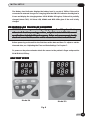
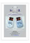
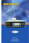
MODEL 3X Series
User ’s Manual
Pulse Oximeter with options for 24 hour Memory,
Printer & USB / Infrared Ports
MEDIAID INC.
17517 Fabrica Way Suite H
Cerritos, CA 90703 USA
(Tel) 714-367-2848 (Fax) 714-367-2852
Email: [email protected]
Website: www.mediaidinc.com
5SERS-ANUAL
-ODEL83ERIES
0ULSE/XIMETERWITHOPTIONSFORHOUR-EMORY
0RINTER53")NFRARED0ORTS
-ODELS
)DEULFD:D\6XLWH+
&HUULWRV&$86$
7HO)D[
ZZZPHGLDLGLQFFRP
LQIR#PHGLDLGLQFFRP
¹-EDIAID)NC!LLRIGHTSRESERVED
(& 5(3
-$33'MB(
3CHIFFGRABEN
(ANNOVER'ERMANY
I
TABLE OF CONTENTS
CHAPTER 1: PRINCIPLES OF OPERA
TION ............................................................ 1
OPERATION
INTENDED USES ............................................................................................... 1
PRINCIPLES OF PULSE OXIMETRY .................................................................... 1
INTRINSIC CALIBRATION .................................................................................. 2
PRINCIPAL FEATURES ........................................................................................ 2
CAUTIONS ........................................................................................................ 2
CHAPTER 2: FEA
TURES, INDICA
TORS, KEYS AND SYMBOLS ............................. 6
FEATURES,
INDICAT
PULSE OXIMETER FRONT & BACK VIEW ............................................................ 6
PULSE OXIMETER SIDE & TOP VIEW .................................................................. 7
PULSE OXIMETER VISUAL DISPLAY ................................................................... 7
SYMBOLOGY & MARKINGS ............................................................................... 8
KEYPADS & DEFINITIONS ................................................................................... 9
CHAPTER 3: INITIAL SETUP ................................................................................ 13
UNPACKING AND INSPECTION ..................................................................... 13
TESTING ........................................................................................................ 13
INSTALLING THE BATTERY ............................................................................. 13
CHARGING THE BATTERY .............................................................................. 14
POWERING ON THE PULSE OXIMETER ......................................................... 15
POWERING OFF THE PULSE OXIMETER ......................................................... 17
ORING AND RECORDING ................................................. 18
CHAPTER 4: MONIT
MONITORING
PERFORMANCE CONSIDERATIONS ............................................................... 18
MONITORING PULSE OXIMETRY (MODEL 30 ONLY) ................................... 19
MONITORING PULSE OXIMETRY (MODEL 34 ONLY) ................................... 19
RECORDING DATA IN MEMORY (MODEL 34 ONLY) ...................................... 20
CHAPTER 5: RECORDING SLEEP SCREENING DA
TA (MODEL 34 ONLY) ........... 24
DAT
SLEEP SCREENING SETUP ............................................................................... 24
CHAPTER 6: DA
TA RETRIEV
AL (MODEL 34 ONLY) .............................................. 26
DAT
RETRIEVAL
VIEWING TREND ............................................................................................ 26
TRANSMITTING DATA TO A PRINTER ............................................................ 27
TRANSMITTING DATA TO A COMPUTER ....................................................... 28
GETTING READY TO TRANSMIT DATA ........................................................... 28
SELECTING THE COMPUTER TRANSMISSION METHOD ............................... 28
TRANSMITTING THE STORED DATA .............................................................. 29
ii
CHAPTER 7: CHANGING THE PULSE OXIMETER
S SETTINGS
OXIMETER’S
(MODEL 34 ONLY) ........................................................................................................ 31
ADJUSTING THE TIME AND DATE SETTINGS ................................................. 31
ADJUSTING THE ALARM SETTINGS ............................................................... 31
VIEW OF THE OPERA
TING MODES ...................................... 33
CHAPTER 8: OVER
OVERVIEW
OPERATING
MONITORING MODE ..................................................................................... 33
CHAPTER 9: SPECIAL KEY FUNCTIONS (MODEL 34 ONLY) ............................... 34
POWER ON FUNCTION OF A KEY ................................................................. 34
CHAPTER 10: SPECIFICA
TIONS .......................................................................... 37
SPECIFICATIONS
PERFORMANCE ............................................................................................... 37
ELECTRICAL ..................................................................................................... 37
ENVIRONMENTAL ........................................................................................... 38
PHYSICAL ........................................................................................................ 38
EQUIPMENT CLASSIFICATION ........................................................................ 38
CHAPTER 1
1: ACCESSORIES ............................................................................... 39
11:
SENSORS ........................................................................................................ 39
USB CABLE/CONNECTOR (MODEL 34 ONLY) ................................................ 40
BATTERY CHARGING/AC-DC ADAPTER ......................................................... 40
BATTERY ........................................................................................................ 40
INFRARED PRINTER (MODEL 34 ONLY) .......................................................... 40
CHAPTER 12: MAINTENANCE AND MISCELLANEOUS ...................................... 41
CLEANING ...................................................................................................... 41
LED DISPLAY CODES (MODEL 34 ONLY) ........................................................ 41
TROUBLESHOOTING ..................................................................................... 42
ERROR CODES ................................................................................................ 42
CHAPTER 13: MEDIAID INC. LIMITED WARRANTY ........................................... 44
APPLICABILITY OF WARRANTY ........................................................................ 44
WARRANTY COVERAGE .................................................................................. 44
MEDIAID INC. PROBLEM CORRECTION PLAN ................................................. 44
OWNER’S REGISTRATION ............................................................................... 45
CHAPTER 14: USER REFERENCES ....................................................................... 46
CONTACT / CUSTOMER SERVICE INFORMATION .......................................... 46
PRODUCT INFORMATION ............................................................................. 47
WARRANTY REGISTRA
TION FORM ................................................................... 49
REGISTRATION
iii
CHAPTER 1: PRINCIPLES OF OPERATION
INTENDED USES
The Mediaid model 3X pulse oximeters are intended to non-invasively measure arterial
oxygen saturation and pulse rate in hospitals, physician’s offices, emergency medical
facilities, or at home. The model 34 can store data in memory for later review and
documentation and also features a sleep mode for patient sleep screening.
IMPORTANT NOTE : The Mediaid model 30 pulse oximeter can be used
for spot checks only. It does not have alarm facility, storing and retrieval
of data, IR, USB features.
WARNING: Before using the pulse oximeter, become thoroughly familiar
with the information in this manual.
WARNING: Model 3X refered through out this manual refers to the
common features of Model 30 & 34. Model 34 has more features and
hence additional instructions are given throughout this manual for proper
& safe use. They are marked as (For Model 34 only). Similarly specific
instructions pertaining to Model 30 are marked as (For Model 30 only)
WARNING: The model 3X is intended only as an adjunct in patient
assessment. It must be used in conjunction with clinical signs and
symptoms.
PRINCIPLES OF PULSE OXIMETRY
The Mediaid model 3X pulse oximeter is designed to measure the percentage of functional
oxygenated hemoglobin to total hemoglobin.
Noninvasive arterial oxygen saturation measurement is obtained by directing red and
infra red light through a pulsating vascular bed. The pulsating arterioles in the path of the
light beam cause a change in the amount of light detected by a photodiode. The pulse
oximeter determines the oxygen saturation of arterial blood by measuring the ratio of
transmitted red to infrared light within the pulse waveform. The non-pulsatile signal is
removed electronically for the purpose of calculation. Therefore, skin, bone, and other
non-pulsating substances do not interfere with the measurement of arterial oxygen
saturation.
PAGE
1
PRINCIPLES OF OPERATION
INTRINSIC CALIBRATION
The light absorption by hemoglobin is wavelength-dependent. Mediaid red and infrared
LED (light emitting diode) wavelengths are tightly controlled by testing in production.
PRINCIPAL FEATURES
The Mediaid model 3X pulse oximeter is a portable, lightweight, pocket-sized instrument
that monitors both functional arterial oxygen saturation (SpO2) and pulse rate non
invasively.
The principal features of the model 3X pulse oximeters are as follows:
z
Displays SpO2 percentage (%SpO2) and pulse rate (BPM- Beats per minute) on a 3digit, 7-segment LED Display.
z
Displays Perfusion Quality (PQ) & Pulse Amplitude (PA) in bargraph displays.
z
Works with any Mediaid sensors with the CompuShield® connector.
z
Provides increased longevity and functionality to the pulse oximeter with the removable
and replaceable sensor modules.
The Model 34
z
Tags patient readings automatically with Patient number, the time and date of the
reading.
z
The model 34 can retain upto 136 hours of information for a single patient, making the
device useful for treadmill and other long tests.
z
The model 34 can be used in walk around test, storing more than 7200 data for upto
20 consecutive patients.
z
The model 34 can also be used for sleep screening where data can be stored every 5
seconds for up to 18 hours.
z
Enables data to be printed or transmitted to a computer via the INFRARED PORT or the
USB PORT.
z
Includes one button that allows for different modes of data storage and the transmission
of recorded data to a printer or a computer.
z
Performs approximately 24 hours of operation on a single rechargeable Lithium ion
battery. (Sleep Mode)
CAUTIONS
General Cautions
z
The model 3X is restricted to sale by or on the order of a physician. It is a prescription
device and is to be operated by qualified personnel only.
z
Become thoroughly familiar with the information in this user’s manual and all the
other accompanying documents before using the pulse oximeter.
z
2
PAGE
Do not attempt to modify or repair the pulse oximeter – doing so voids the warranty.
PRINCIPLES OF OPERATION
z
Dispose of this instrument and its accessories according to governmental regulations.
z
Adhere to all cautions, stipulations, and instructions included with the sensors used.
z
Explosion hazard. Do not use model 3X in presence of flammable anesthetics or gases.
Do not use model 3X in presence of any flammable agents.
z
The use of equipment is restricted to one patient at a time.
z
Use accessories specified by our company only, otherwise; the device may not function
normally.
z
The system may not meet its performance specifications if stored or used outside the
specified temperature and humidity ranges.
z
Do not drop the model 3X oximeter or its accessories which may result in certain
damage.
z
Do not use a model 3X oximeter, Charger, AC power cord, sensor, sensor cable or
connector and USB Cable that appears to be damaged or broken. Failing to comply
with this may result in damage or electric shock hazard to the user/operator as
mechanical/electrical integrity of the monitor and/or its accessories could have been
hampered.
z
Use of damaged sensor or oximeter may result in erroneous or faulty readings or no
alarm.
z
Do not attempt to lift the oximeter by its charger cable, usb cable or sensor cable. Any
attempt made to lift may result in the detachment of the cables and the fall of the
oximeter resulting in damage.
Environmental Cautions
z
Do not use the pulse oximeter in the presence of flammable agents or flammable
anesthetics.
z
Do not immerse in liquid and do not allow any liquid to penetrate the pulse oximeter’s
z
Operate the pulse oximeter in normal light conditions.
z
Avoid bright light or glare on the sensing area to ensure correct reading of the displays
interior.
and indicators.
z
Keep away from MRI (Magnetic Resonance Imaging) equipment.
z
Move the pulse oximeter away from other electromagnetic emitting equipment if you
experience interference problems. (This device complies with electromagnetic
compatibility standard EN60601-1-2.)
z
Keep away from the equipment that emitsm x-ray, alpha particles, beta particles,
neutrons particles, or microwave emissions.
PAGE
3
PRINCIPLES OF OPERATION
Battery Cautions
z
Use only Li-ion batteries specified by Mediaid. Use of any other type of battery not
specifically recommended. Use of such batteries could damage the pulse oximeter.
z
Never dispose of batteries into fire, short-circuit the terminals, or attempt to
disassemble or heat the battery. Doing so could damage the battery and cause a fire,
injury, or environmental contamination.
z
Liquid leaking from battery can cause skin burns or damage the pulse oximeter. If a
battery leaks inside the instrument, return the pulse oximeter for servicing.
z
Remove the battery during shipment or if the pulse oximeter will be idle for several
weeks.
Sleep Screening Cautions (MODEL 34 ONLY)
Powering OFF the model 34 while it is in the Sleep Recording mode will end the sleep
screening process. The next time that the pulse oximeter is powered ON (with the
sensor attached) will result in recording of new sleep screening data.
z
Removing the sensor from the model 34 while it is in Sleep Recording mode will
power OFF the instrument after 2 minutes, ending the sleep screening process.
z
When sleep screening data is gathered overnight, the sensor cord should be placed
such that the patient does not become entangled. Do not attach the cord or the pulse
oximeter in any permanent or semi-permanent manner to the bed or furniture. The
sensor cord and the pulse oiximeter should be free to move with the patient.
NOTE: When being used in the sleep mode or in continuous monitoring the sensor
must be checked and repositioned once every 2 or 4 hours. Tissue damage might occur.
Preventing Device Complications and Faulty Readings
z
Trim the patient’s long fingernails and remove artificial nails or thick nail polish.
z
Insert the patient’s finger completely into the sensor.
z
Fit the sensor comfortably without constricting or compressing the application site
when using a sensor that is attached to the cable adaptor.
z
Do not apply the sensor to anything but a well-perfused extremity.
z
Cold extremities can affect readings. Warm up the extremity, or move the sensor to a
different site, if necessary.
z
Do not apply the sensor on extremities that have blood pressure cuffs or arterial or
venous catheters.
4
PAGE
z
Avoid extremity positions that could compromise venous return.
z
Check for intravascular dyes, which could affect pulse oximeter readings.
PRINCIPLES OF OPERATION
z
Turn off very bright lights, such as surgical, bilirubin, fluorescent, or infrared heating
lights if they interfere with sensor functioning. In cases where such lights are unavoidable,
cover the sensor site with an opaque material.
z
Route sensor cords carefully.
z
Avoid applying excessive tension to the sensor or sensor cord.
z
Consider conditions affecting the hemoglobin dissociation curve when interpreting
pulse oximeter readings (such as intravascular dyes).
z
Keep patient movement to a minimum.
z
When not in use, do not wind the sensor cord around the pulse oximeter.
PAGE
5
CHAPTER 2: FEATURES, INDICATORS, KEYS AND SYMBOLS
PULSE OXIMITER FRONT & BACK VIEW
Model 34
Model 30
Fig. 1
Model 34
Model 30
Fig. 2
6
PAGE
FEATURES, INDICATORS, KEYS AND SYMBOLS
PULSE OXIMETER SIDE & TOP VIEW
Fig. 3
DC inlet/Battery Charger
USB Port (Model 34 only)
Fig. 4
Infrared Port/Window
(Model 34 only)
Sensor inlet
Fig. 5
PULSE OXIMETER VISUAL DISPLAY
%SpO2 Reading
Pulse
Amplitude
Bar graph
Perfusion
Quality
Bar graph
Pulse Reading (Beats per minute)
Fig. 6
PAGE
7
FEATURES, INDICATORS, KEYS AND SYMBOLS
SYMBOLOGY & MARKINGS
Symbol
Definition
%SpO2
Oxygen Saturation Percentage
Heart Beats per Minute (BPM)
PA
Pulse Amplitude Indicator
PQ
Perfusion Quality Indicator
Power On/Off
Alarm Off Key and Indicator
SEND
Multi Function Key for Communication
Increment Key
Decrement Key
RATE
ALARM
High Pulse Rate Alarm
RATE
ALARM
Low Pulse Rate Alarm
SAT
ALARM
High Oxygen Saturation Alarm
SAT
ALARM
Low Oxygen Saturation Alarm
Low Battery Indicator (Blinking Red LED)
Fully Charged Battery Indicator (3 Green or Red LED)
Partially Charged Battery Indicator (2 Green or Red LED)
USB Key Symbol
DC Power Connection
Attention: Consult Accompanying Documents
Non-anesthetic Proof
Type BF Applied Part
8
PAGE
FEATURES, INDICATORS, KEYS AND SYMBOLS
KEYPADS & DEFINITIONS
Refer respective key number below in the definitions
9
3
2
4
6
7
1
5
Model 34
8
2
1
Model 30
Fig. 6
1.
POWER ON/OFF KEY
The unit powers ON with a short depression of the POWER ON/OFF KEY. A onesecond display and indicator test is performed automatically, and all the segments of
Light Emitting Diodes (LEDs) will be illuminated. The software version number will
then be displayed as “Ver” in %SpO2 display area and the version number in
display area accompanied by a long beep.
Unit switches off automatically (auto-power off) when there is no sensor connected
or no finger in sensor for more than 2 minutes.
The unit power OFF with a short-depression of the Power ON/OFF Key.
PAGE
9
FEATURES, INDICATORS, KEYS AND SYMBOLS
2.
BATTERY LEVEL INDICATOR
HI
LO
The Battery level indicator displays the battery level in a scale of 3. If the unit is
connected to external power supply for charging (irrespective of whether the unit is
ON or OFF), then the level indicator glows Green and displays the charging status. The
LSB LED glows, if the charger is connected. The LSB & Middle LEDs glow, if the unit
is partially charged. All 3 LEDs LSB, Middle and MSB glow if the unit is completely
charged.
If the unit is operating in Battery mode, then the battery level indicator glows in Red. All
three LEDs (MSB, Middle, LSB) glow if the battery voltage is between 91% to 100%
voltage. 2 LEDs glow (middle & LSB) if the battery voltage is in the range of 87% to 90%.
One LED (LSB) glows ON if the battery voltage is in the range of 71% to 87%.
CAUTION: Below 71% the LSB LED blinks indicating that the battery is near depletion
and the unit will shut down within 5 minutes time.
3.
ALARM OFF (MUTE) KEY
A short depression of this key silences the alarm for a period of 60 seconds. The ALARM
OFF INDICATOR illuminates and remains on constantly, and the oximeter monitors
normally. Silenced alarms can be reactivated by a short depression of the ALARM OFF
KEY or automatically after a period of 60 seconds regardless of new alarms. This key can
be used as enter key while entering a data in model 34.
CAUTION: Do not silence the audible alarm or decrease its volume else the patient
safety could be compromised
4.
ALARM OFF INDICATOR
The ALARM OFF INDICATOR illuminates and remains on constantly when audible alarms
are silenced.
5.
OXYGEN SATURATION ALARM KEY
SAT
ALARM
Short depression of the OXYGEN SATURATION ALARM KEY toggles the LED display
between the high and low alarm settings, and respective HI/LO ALARM INDICATOR
glows below the key. These alarm settings are adjusted using UP ARROW and DOWN
ARROW KEYS. The alarm settings are retained in memory until reset by the user. (The
default alarm settings for adult / neonate are minimum of 85% for Low limit and
10
PAGE
FEATURES, INDICATORS, KEYS AND SYMBOLS
100%/95% for high limit respectively.) The display reverts back to normal monitoring
after six seconds of key inactivity or Mute key press. The high/low reading of Oxygen
Saturation keeps blinking when the reading is above the maximum preset value and
when reading is below the minimum preset value.
6.
PULSE RATE ALARM KEY
RATE
ALARM
Short depression of the PULSE RATE ALARM KEY toggles the LED display between the
high and low alarm settings and respective HI/LO ALARM INDICATOR to glow below
the key. These alarm settings can be adjusted using UP ARROW and DOWN ARROW
KEYS. The alarm settings are retained in memory until reset by the user. The default
pulse-rate alarm settings are as per the patient type selected (Adult/Neo): High 170 BPM
and Low 40 BPM for Adult mode and High 190 and Low 90 for Neo mode. The display
reverts back to normal patient monitoring after a six-second period of key inactivity or
Mute key press.
CAUTION: Each time the monitor is used, check the alarm limits to ensure that they are
appropriate for the patient being monitored.
7.
UP & DOWN ARROW KEYS
The pulse-tone volumes are adjusted using the UP & DOWN ARROW KEYS. There are
5 levels of audible (pulse) tone volume, and “off.” The pulse tone volume is increased
with the UP ARROW key, and decreased or silenced with the DOWN ARROW key.
Default pulse-tone volume level is 3. Alarm levels are also adjusted with these keys
during alarm condition but the alarm volume is never zero. UP & DOWN arrows keys
also used to scroll through the menu, during mode selection (i.e. Storage mode selection,
trend values, patient number, etc.).
8.
VISUAL HI/LO ALARM INDICATORS
SAT
ALARM
RATE
ALARM
These indicators are located close to the OXYGEN SATURATION ALARM and PULSE
RATE ALARM keys; these indicators illuminate when the patient’s oxygen saturation or
pulse rate crosses the preset high or low alarm settings. While setting alarm limits, the
appropriate indicator is illuminated. During the high or low reading of SpO 2 or pulse
rate corresponding indicator would be ON.
PAGE
11
FEATURES, INDICATORS, KEYS AND SYMBOLS
9.
PRINT / SEND KEY
SEND
A long press of the SEND key transmits all the stored data to a computer through USB/IR
or a printer through the IR port. In Auto Mode, short press of the SEND key starts storing
the data in the memory and in Intermittent Mode, every short press of the SEND key
stores the displayed data in the memory.
12
PAGE
CHAPTER 3: INITIAL SETUP
UNPACKING AND INSPECTION
Notify the carrier if the shipping carton is damaged. Unpack the model 3X and
components. If anything is missing or damaged, contact Mediaid Technical Support.
TESTING
Before using the model 3X in a clinical setting, verify that the unit functions properly by
following the instructions in the section on “Powering ON the Pulse Oximeter” in this
chapter.
Also check if any error codes are displayed.
INSTALLING THE BATTERY
The model 3X pulse oximeters are powered by a single Li-ion battery that will operate for
approximately 24 hours with a fully charged battery in sleep mode.
Pull out the Battery
Connector
To open the battery enclosure
remove the screw indicated here
Fig. 7
PAGE
13
INITIAL SETUP
To replace the battery, complete the following steps.
1. Unscrew the Battery cover on the rear of the oximeter.
2. Disconnect and Remove the battery.
3. Insert the new battery and attach the connector. Put back the rear cover and tighten the
screw.
CAUTION: While replacing battery, ensure that the proper tools are used to remove/fix
the screw. Using a wrong tool may result in screw head portion getting broken.
CAUTION: To ensure patient safety, do not place the monitor in any position that might
cause it to fall on the patient.
CAUTION: As with all medical equipment, carefully route patient cabling to reduce the
possibility of patient entanglement or strangulation.
CAUTION: Explosion hazard. Do not use the model 3X handheld pulse oximeter in the
presence of flammable anesthetics.
CAUTION: Follow local governing ordinances and recycling instructions regarding
disposal or recycling of device components, including batteries of the model 3X.
CAUTION: Always adhere to all cautions detailed in “Battery Cautions,” in Chapter 1.
CAUTION: Do not remove the battery from the pulse oximeter when it is in any of the
recording modes (Automatic, Intermittent, or Sleep). Doing so can result in the loss of
stored data.
CAUTION: Ensure that the battery connector is inserted correctly to avoid reverse polarity
of the battery. Trying to connect the battery in reverse polarity may damage model 3X
and / or its components.
CHARGING THE BATTERY
Connect Model 3X to the specified charger unit. Battery is charged by attaching the
given charger to the AC inlet and turning it ON. While charging the battery level indicator
glows in Green.
14
PAGE
INITIAL SETUP
The Battery level indicator displays the battery level in a scale of 3LEDs. If the unit is
connected to external charger for charging, then the LSB LED indicator should glow in
Green and display the charging status. LSB & Middle LEDs glow, if the unit is partially
charged (about 70%). All three LSB, Middle and MSB LEDs glow if the unit is fully
charged.
POWERING ON THE PULSE OXIMETER
WARNING: To ensure personal safety and proper operation of the pulse oximeter,
adhere to all directions, warnings, cautions, and policies stated within this manual
as well as those included with each accessory. Before each measurement, visually
check and ensure that the monitor and its accessories are intact and safe for use.
Before powering on the unit for the first time set the date and time. To adjust or set the
time and date, see “Adjusting the Time and Date Settings” in Chapter 7.
To power on the pulse oximeter attach the sensor to the patient’s finger and press the
POWER ON/OFF key.
SELF TEST STATE
Model 34
Model 30
Fig. 8
PAGE
15
INITIAL SETUP
After the pulse oximeter is powered on, all the segments of 7 segment LED DISPLAY,
BARGRAPHS are turned ON and all LEDs in the Keypad are also turned ON for about 12 seconds. This is as a part of self test to ensure that all display segments are functional.
On completion of visual indicator test, the software version number is displayed with a
long beep for a second to ensure that the audio circuitry is functional.
MODEL 3X DISPLAYING SOFTWARE VERSION
Fig. 9
CAUTION: A non-functioning LED segment will result in an incomplete numeral and
possible erroneous reading.
CAUTION: A non-functioning beeper may result in compromising of patient safety. Do
not use model 3X when there is no beep sound during self-test.
16
PAGE
INITIAL SETUP
The LED DISPLAY shows one of the following for 1 second: (MODEL 34 ONLY)
z
Ato, if the pulse oximeter is in the Automatic Recording mode.
z
int, and the patient number (from P01 to P 20) if the pulse oximter is in the Intermittent
Recording mode. If a patient number has not been selected, the LED display shows P
and two dashes (P - -).
z
SLP, if the pulse oximeter is in the Sleep Recording mode.
Next, the pulse oximeter tests the sensor availability, internal functions, and the battery
status. The LED DISPLAY of both SpO2 and BPM shows three dashes (- - -) during these
tests, which last for about 1-2 seconds.
When the pulse oximeter has successfully passed the power-on tests, it enters the
Monitoring Mode. The battery condition is monitored continuously and the battery level
indicator displays the charge on the battery. An error Code is shown if any other
malfunction occurs. See “Troubleshooting”, in Chapter 12, for error code interpretation.
POWERING OFF THE PULSE OXIMETER
z
To power off the pulse oximeter in any mode remove the finger from the sensor and
press the POWER ON/OFF key.
z
Remove patient’s finger from the sensor or detach the sensor cable from the oximeter,
the oximeter switches off after a period of 120 seconds.
CAUTION: Powering off model 34 while it is in the sleep recording mode will end the
sleep screening process. The next time that the instrument is powered on (while sensor
is attached) new sleep data will be recorded. Ensure that the data recorded is transmitted
to a computer using USB cable/IR as soon as the sleep screening process is completed,
failing which may result in loss of stored data.
In Model 34, In the Sleep Recording mode, the LED DISPLAY will dim and beeper will
automatically mute after 30 seconds without any key activity. Press any key on the pulse
oximeter to re-illuminate the LED DISPLAY & activate beeper for another 30 seconds.
PAGE
17
CHAPTER 4: MONITORING AND RECORDING
In Model 30, Pulse oximetry data can be displayed and has only Monitoring mode.
In Model 34,Pulse oximetry data can be displayed in the Monitoring mode, or it can be
recorded and stored in the Intermittent, the Automatic, or the Sleep recording mode.
PERFORMANCE CONSIDERATIONS
Pulse oximeter readings and pulse signal can be affected by certain ambient environmental
conditions, sensor application errors, and certain patient conditions.
Inaccurate measurements can be caused by:
z
Incorrect application of the sensor. Incorrect application may cause tissue damage.
Inspect the sensor site periodically as directed in the sensor directions for use.
z
Placement of the sensor on an extremity with a blood pressure cuff, arterial catheter, or
intravascular line
z
Ambient light
z
Patient movement
CAUTION: Calibration cannot be performed by the user/operator. Please contact Mediaid.
CAUTION: Reusing the device/sensor without prior cleaning may result in cross
contamination.
Loss of pulse signal can occur for the following reasons:
z
The sensor is too tight
z
A blood pressure cuff is inflated on the same extremity as the one with the sensor
attached
z
There is arterial occlusion proximal to the sensor
Clean and remove any substances such as nail polish from the application site. Periodically
check to see that the sensor remains properly positioned on the patient.
z
High ambient light sources such as surgical lights (especially those with a xenon light
source), bilirubin lamps, and direct sunlight can interfere with the performance of a
SpO2 sensor. To prevent interference from ambient light, ensure the sensor is properly
applied, and cover the sensor site with opaque material.
z
Failure to take this precaution in high ambient light conditions may result in inaccurate
measurements.
18
PAGE
MONITORING AND RECORDING
MONITORING PULSE OXIMETRY (MODEL 30 ONLY)
The model 30 can be used only for spot checks. It does not have alarm, storing and
retrieval of data, IR, USB features. Do not attempt to use for continuous monitoring, as it
may endanger the patient.
z The Monitoring mode is started by placing the finger in the sensor and powering on
the monitor. In Monitoring mode, pulse oximetry data can be viewed on the LED
DISPLAY, as follows:
z Top 3 LED DISPLAY indicates %SpO2.
z Bottom 3 LED DISPLAY indicates BPM (Beats per minute)
z Two Bar graph displays (scale of 1 to 10), Left one indicates PULSE AMPLITUDE (PA)
and the right one indicates PERFUSION QUALITY (PQ).
z Powering on the LED DISPLAY shows three dashes one each for SpO2 and BPM
indicators for 1-2 seconds while the pulse oximeter performs the power-on self tests.
z After the power-on tests, the following information shows on the pulse oximeter:
z
The PA Bar graph begins to blink, indicating the start of
measurement. Then PQ Bar Graph starts to blink to the level
of perfusion at the measuring site.
z
Both SpO2 and BPM values are displayed.
z Record the readings if required and switch off the model 30 to save battery power.
z This completes one cycle of measurement using the model 30.
z Please follow the cleaning instructions given in the manual before making next
measurement on another patient.
NOTE: If the PQ and PA don’t blink adjust the sensor position.
CAUTION: When Perfusion Quality (PQ) display is showing less than 3 LED Bars, it
indicates that the PQ is too low. Either change the monitoring site to an alternative
location or check if the sensor is applied correctly.
CAUTION: Reusing the device/sensor without prior cleaning may result in cross
contamination.
MONITORING PULSE OXIMETRY (Model 34 only)
The Monitoring mode is started by placing the finger in the sensor. In Monitoring mode,
pulse oximetry data can be viewed on the LED DISPLAY, as follows:
z Top 3 LED DISPLAY indicates %SpO2.
z Bottom 3 LED DISPLAY indicates BPM (Beats per minute)
z Left Bar graph displays (scale of 1 to 10) indicates PULSE AMPLITUDE (PA)
z Right Bar graph displays (scale of 1 to 10) indicates PERFUSION QUALITY (PQ).
PAGE
19
MONITORING AND RECORDING
To monitor pulse oximetry data without recording the data in memory (possible only
in Auto & Intermittent mode without pressing the send key), complete the following
steps:
1. After powering on (in Auto or Intermittent mode) the LED DISPLAY shows three dashes
(- - -) for SpO2 and BPM indicators for 1-2 seconds while the pulse oximeter performs
the power-on self tests.
2. After the power-on tests, the following information shows on the pulse oximeter:
z The PA Bar graph begins to blink, indicating the start of measurement.Then PQ Bar
Graph starts to blink to the level of perfusion at the measuring site.
z Both SpO2 and BPM values are displayed.
CAUTION: When Perfusion Quality (PQ) display is showing less than 3 LED Bars, it
indicates that the PQ is too low. Either change the monitoring site to an alternative
location or check if the sensor is applied correctly.
RECORDING DATA IN MEMORY (MODEL 34 ONLY)
The pulse oximeter can record pulse oximetry data either intermittently (on upto 20
patients) or automatically every 1 minute for a patient. In addition it has a Sleep Recording
mode that can record pulse oximetry data every 5 seconds up to 18 hours for single
patient.
CAUTION: Changing the modes of operation will completely erase the previously stored
data.
Recording Data Intermittently
The following conditions apply to the Intermittent Recording mode:
z Data can be manually recorded on up to 20 different patients.
z The time and date are recorded with each data entry.
z Recorded data can be either printed or transmitted to a computer.
To record data in memory, the time and the date must be set first . See “Adjusting the
Time and Date Settings”, in chapter 7, for more information.
To record data intermittently, complete the following three procedures: “Selecting the
intermittent recording mode”, “Entering a patient number”, and “Recording the
Intermittent Data”.
20
PAGE
MONITORING AND RECORDING
Selecting the Intermittent Recording mode
1. If the oximeter is on, Power it off
2. Press the down arrow key and power ON/OFF key.
3. After 4 seconds of showing “int”, the LED DISPLAY will show (—), indicating that all
previously stored data of Auto/Sleep Mode has been erased.
Entering Patient Number
When the pulse oximeter is in the Intermittent Recording mode, the patient number from
P1 to P20 shows on the LED DISPLAY at power-on, unless a patient number has not
been selected.
The patient number can be adjusted or entered when the pulse oximeter is in the
Intermittent Recording mode (see “Selecting the Intermittent Recording Mode” for more
information.)
1. Power on the pulse oximeter, taking note of the patient number that appears for 1
second after power on.(if a patient number has been entered)
If a patient number has not been entered, the LED DISPLAY will show three dashes (- -) at power-on.
2. To increase or to enter a patient number, press the down or up arrow key.
If a patient number has not been entered, and unit is powered on in INT mode from
AUTO or SLEEP mode the display shows (P - -) indicating no patient number is selected.
Recording the Intermittent Data
The pulse oximeter is ready to record intermittent data when it is in the Intermittent
Recording mode and a patient number has been selected (see “Selecting the Intermittent
Recording Mode” and/or “Entering a Patient Number” for more information).
1. Apply the sensor to the patient.
2. Power on the pulse oximeter.
The patient number (from P01 to P20) will show briefly on the LED DISPLAY, and then
the pulse oximeter will begin normal monitoring.
3. To record the data showing on the LED DISPLAY, press the send key.
The data will flash two or three times to indicate that it has been recorded. Each time
the SEND key is pressed, both oxygen saturation and pulse rate data are recorded,
regardless of what shows on the LED DISPLAY.
4. To record data under a different patient number, without erasing previously stored
data, enter a new patient number and repeat steps 1-3, above.
PAGE
21
MONITORING AND RECORDING
See “Entering a Patient Number” for more information.
The data recorded can be retrieved; either by printing or by transmitting to a computer
(see Chapter 6).
Recording Data Automatically on a Single Patient
The following conditions apply to the Automatic Recording mode:
Data is recorded every 1 minute for a single patient. The time (Hour, Min) and date
(Year, Month & Date) are also recorded and the data can either be printed or transmitted
to the computer.
To record data in memory the time and the date must be set first. To adjust or set the time
and date, see “Adjusting the Time and Date Settings” in Chapter 7.
To record data automatically, complete the following two procedures: “Selecting the
Automatic Recording Mode,” and “Recording the Automatic Data”.
Selecting the Automatic Recording Mode
1. If the pulse oximeter is on, power it off.
2. Press the DOWN ARROW KEY, and the Power ON/OFF key simultaneously.
Either Int, Ato or SLP (Intermittent, Automatic, or Sleep Recording mode)shows on the
LED DISPLAY.
3. If Int or Slp shows on the LED DISPLAY press the UP/DOWN arrow key till Ato is
displayed. After 4 seconds, three dashes (- - -) shows on both %SpO2 and
displays. Indicating all previously stored data has been erased, and now the pulse
oximeter is ready for monitoring in Auto mode.
Recording the Automatic Data
The pulse oximeter is ready to record automatic data when it is in the Automatic mode
(Read “Automatic Recording Mode” for more information).
1. Apply the sensor to the patient.
2. Press the power ON/OFF key to power on the pulse oximeter.
Ato will show briefly on the LED DISPLAY, and then the oximeter will begin normal
monitoring.
22
PAGE
MONITORING AND RECORDING
3. Short press of the SEND/PRINT key would start/stop the recording process. Both the
displays will flash once to indicate the commencement of recording.
Erasing stored Data
Press SAT ALARM key and RATE ALARM key together at any time when the unit is ON
for about 6 seconds. Both the LED DISPLAYS will blink indicating that the memory is
cleared.
PAGE
23
CHAPTER 5: RECORDING SLEEP SCREENING DATA
(MODEL 34 ONLY)
SLEEP SCREENING SETUP
CAUTION: If data has been stored under the Intermittent or Automatic Recording modes,
changing to the Sleep Recording mode will erase the stored data.
NOTE: Before starting sleep screening process charge the battery fully or use a fresh
battery.
1. If the model 34 is on, power it off. Connect the sensor.
2. Press DOWN ARROW KEY & POWER ON/OFF keys together. The current mode is
displayed. If Ato or int is displayed then scroll using arrow keys till SLP is displayed.
After about 4 seconds three dashes (- - -) are displayed both in SpO2 and BPM indicators.
3. Data is stored every 5 seconds upto 24 hrs for a single patient. Switching off the unit in
sleep mode can be done by detaching sensor and without key activity for 2 minutes
switches off the unit automatically or by pressing the power button.
4. Give the model 34 and a copy of the “Patient Sleep Screening Instructions” to the
patient for a home sleep study.
The “Patient Sleep Screening Instructions” can be found on a separate sheet included
with the model 34, as well as in the following section.
5. To transmit the sleep screening data to a computer, follow the instructions
in”Transmitting Data to a Computer” in Chapter 6.
Sleep screening data can be transmitted to a computer and then printed, but it cannot
be transmitted directly to an infrared printer.
Patient Sleep Screening Instructions
Your health care provider has given you the Mediaid model 34 pulse oximeter so that
you can record your oxygen saturation data while you sleep. Carefully read the following
instructions.
1. Place the sensor given along with the model 34 on your right or left index finger so that
the transmitting LED lies above the middle of your fingernail.
The angle of the sensor can be opened wider if the fit is too tight. Avoid any
constriction of your finger.
24
PAGE
RECORDING SLEEP SCREENING DATA
2. Tear off a 4-5 inch strip of
¼
or
½
inch paper tape.
3. With the sensor resting comfortably on your finger, wrap the tape around your finger
and the sensor.
4. Press the tape against the skin on both sides of your finger.
5. Turn the model 34 on by pressing POWER ON/OFF key.
The model 34 will display SLP for a few seconds and will then start to monitor your
oxygen saturation and pulse rate. After about 30 seconds, the display will dim.
6. Place the model 34 next to you while you sleep.
WARNING: Carefully place the sensor cord so that you do not become
entangled while you sleep. Do not attach the sensor cord or the model
34 to the bed or the furniture. The sensor cord and the model 34 should
be free to move with you throughout the night.
7. Do not remove the sensor from your finger until the study is finished.
NOTE: The model 34 should be carried with you if you get up during the night.
Monitoring can continue for as long as 24 hours.
8. When the study is finished (most likely when you wake up in the morning), turn the
model 34 off by disconnecting the sensor – squeeze the tabs on either side of the
sensor connector and pull it away from the model 34.
9. Please ensure that the saved data is transmitted to computer/laptop.
PAGE
25
CHAPTER 6: DATA RETRIEVAL (MODEL 34 ONLY)
VIEWING TREND
Data can be viewed on the oximeter itself by switching ON the oximeter in the
following manner. Press SAT ALARM key and switch ON the oximeter using the
POWER ON/OFF key together. The data is displayed depending on the modes. The
arrow keys are used for scrolling between time and patient number (in case of
intermittent mode).
In Intermittent mode the display is in the following order. First the patient number
and the date is displayed in SpO2 and BPM displays respectively. Next the reading is
displayed. After this the time (hour and minute) when the corresponding reading was
taken is shown. Arrow keys are used to scroll between readings and patient.
In Automatic mode the display is the following order. First the time (hour & minute)
is displayed in SpO2 and BPM. Next the reading is displayed. Arrow keys are used for
scrolling.
In Sleep mode the display is in the following order. First the reading is shown followed
by the time (hour and date). Arrow keys are used for scrolling.
WARNING: If data receiving equipment is not approved for the patient
environment (not meeting the requirements of IEC 60601-1), remove the
pulse oximeter from the patient environment before transmitting the data.
Stored data can be retrieved by sending it to a computer or printer via the INFRARED
PORT or USB PORT. If the data was stored in the Intermittent or Automatic Recording
mode, it can be transmitted to a printer or computer. All patient information remains in
memory until erased or until the recording mode is changed.
WARNING: Do not change the recording modes without first printing or
transmitting stored data. Doing so will erase all data stored in memory.
26
PAGE
DATA RETRIEVAL
TRANSMITTING DATA TO A PRINTER
Transmitting pulse oximetry data to a printer requires the model 34 & compatible printer
with IR port.
Selecting the Printer Transmission Method
The pulse oximeter has two data transmission methods. To transmit data to a printer, the
Printer Transmission method must first be selected.
The pulse oximetry retains in memory the last method selected. To change, go to the
Printer Transmission method, complete the following steps.
1. If the pulse oximeter is ON, power it OFF.
2. Hold down the SEND key while simultaneously powering ON the pulse oximeter.
Either Prt (for transmission to a printer) or CO (for transmission to a computer) shows
on the LED DISPLAY.
3. If CO shows on the LED DISPLAY, press the arrow keys to scroll and select between
printer and computer transmission methods.
Printing Stored Data
1. With the Printer Transmission method (Prt) selected, power OFF the pulse oximeter,
if necessary.
2. If the sensor is attached then remove the sensor.
3. Align the infrared printer to the INFRARED PORT on the model 34.
The distance between the infrared printer and the INFRARED PORT should be no
more than 6 inches.
4. Power ON the printer.
5. Power ON the pulse oximeter.
6. Send the data to the printer by pressing the SEND key on the pulse oximeter.
While data is being transmitted, the LED DISPLAY on the pulse oximeter displaysPrt,
and a printout is obtained.
CAUTION: If the INFRARED PORT on the model 34 is misaligned with the infrared
receiver on the printer, data transmission will be incomplete. However, data will not be
lost and can be retransmitted.
7. Transmission stops when all data has been received.
PAGE
27
DATA RETRIEVAL
TRANSMITTING DATA TO A COMPUTER
Transmitting pulse oximetry data to a computer requires the following:
· The model 34.
· Infrared Data Converter.
· USB Port and Connector.
· A Personal Computer (PC) or Laptop running Windows 2000, ME, XP, or NT 4.0
SP3-SP6.
· Oxysoft™ software installed on the PC.
GETTING READY TO TRANSMIT DATA
Before transmitting data to a computer, make sure that the following conditions have
been met.
CAUTION: Do not change the recording modes without printing or transmitting stored
data. Doing so will erase all data stored in memory.
z Pulse oximetry data has been stored in memory, using either the Automatic, Intermittent,
or Sleep Recording modes.
z Oxysoft software has been installed. To install the software, follow the instructions on
the CD package and/or the computer screen. A password is required for installation,
which can be found on the back of the CD package.
z Ensure the Infrared Data Converter has been connected to the PC. Connect the serial
cable from the IR Data Converter to the PC’s COM port. The PC COM port is either a
9- or 25- pin D-shaped male connector, usually located on the back of the computer. It
is sometimes labeled “COM1” or “COM2”. Alternately a USB port can be used. A USB
Cable connects the model 34 to the PC’s USB port.
z The Computer Transmission method has been selected for transmitting data (see
“Selecting the Computer Transmission Method”, in this chapter, for more information).
SELECTING THE COMPUTER TRANSMISSION METHOD
The pulse oximeter has two data transmission methods. To transmit data to a computer,
the Computer Transmission method must be first selected.
The pulse oximeter retains in memory the last method selected. To change to the Computer
Transmission method, complete the following steps.
1. If the pulse oximeter is ON, power it OFF.
2. Hold down the SEND key while simultaneously powering ON the pulse oximeter.
28
PAGE
DATA
RETRIEVAL
DATA
RETRIEVAL
Either Prt(for transmission to a printer) or CO (for transmission to a computer)
shows on the LED DISPLAY.
3. If Prt shows on the LED DISPLAY, press the arrow keys to scroll till CO is displayed.
Each press of up or down arrow will toggle the pulse oximeter between the Printer and
Computer Transmission methods (Prt & CO).
NOTE: Follow the insturctions of Oxysoft Softwre for proper and successful data
transmission.
TRANSMITTING THE STORED DATA
To transmit data to a computer, complete the following steps:
1. Power ON the PC and start the Oxy34 program.
2. Align the infrared port on the Infrared Data Converter with the INFRARED PORT on
the model 34.
The distance between the pulse oximeter and the IR Data Converter should be no
more than 6inches.
3. Alternately a USB cable can be used to connect the oximeter and the Computer.
4. On the PC, open the “File” menu, point to “Import”, and then click “model 34”.
The “Import Pulse Oximeter Data, Step 1” screen appears.
5. Follow the on-screen instructions, clicking on the “Next>>” button to proceed to the
next step.
When the data transmission begins, the pulse oximeter’s LED DISPLAY briefly flashes
CO, the end bars of the LED DISPLAY move from top to bottom, and the “Receive
Status” box will flash “RECEIVING”. When data transmission is complete, the “Receive
Status” box will show “FINISHED”.
NOTE: The Infrared Data Converter powers off automatically after 1 minute without any
transmission activity. It might be necessary to power it back on if there is transmission
delay.
NOTE: Sleep screening data can take several minutes to transfer.
6. After the transmission is completed, on the PC, click the “Exit” button on the
“Import Pulse Oximeter Data” window to exit “Import”.
PAGE
29
DATA RETRIEVAL
NOTE: Data Transmission will be incomplete if the INFRARED PORT on the model
34 is misaligned with the IR receiver on the IR Data Converter or Laptop or Computer.
However, data is not lost and can be retransmitted.
30
PAGE
CHAPTER 7: CHANGING THE PULSE OXIMETER ’ SETTINGS
(MODEL 34 ONLY)
ADJUSTING THE TIME AND DATE SETTINGS
To adjust the time and/or date settings, complete the following steps.
1. If the pulse oximeter is on, power it off.
2. Power on the unit while pressing UP ARROW key simultaneously.
3. Adjust the year parameter while it is displayed, to increase/decrease use the arrow
keys.
4. To scroll through the remaining time/date parameters, press the SEND key. The
parameters appear in the following order: Year, Month, Day, Hour and Minute.
NOTE: The model 34 uses 24 hour format for time.
5. Adjust the remaining parameters while they are displayed using arrow keys.
After 6 seconds without key activity, or press of alarm off key, the parameters are set
in memory and the pulse oximeter resumes monitoring.
ADJUSTING THE ALARM SETTINGS
The model 34 has an alarm for low or high readings of SpO2 or BPM which can be set to
the levels as required by the user. The following describes the alarm settings.
Audible Alarm Indicators
The alarm tone is a fixed pitch, and the volume is adjustable. Alarm tones are automatically
silenced when the alarm condition goes away.
z HIGH PRIORITY alarm tones sound 0.75 seconds for every three seconds. HIGH
PRIORITY alarms are caused by conditions such as: low /high oxygen saturation and
pulse rate; no pulse.
z MEDIUM PRIORITY alarm tones sound for 0.75 seconds every five seconds. MEDIUM
PRIORITY alarms are caused by measuring problems such as No finger in sensor, or
a faulty sensor.
z LOW PRIORITY alarm tones sound for one second every 10 seconds. LOW PRIORITY
alarms are caused by disconnected sensor.
PAGE
31
CHANGING THE PULSE OXIMETER’ SETTINGS
Alarm off Key
A short depression of this key silences the alarm for a period of 60 seconds. The ALARM
OFF INDICATOR illuminates and remains on constantly, and the oximeter monitors
normally. Silenced alarms shall be reactivated by a short depression of the ALARM OFF
KEY.
Alarm Off Indicator
The ALARM OFF INDICATOR illuminates and remains on constantly when audible alarms
are silenced.
Oxygen Saturation Alarm Key
Short depression of the OXYGEN SATURATION ALARM KEY toggles the LED display
between the high and low alarm settings, and respective HI/LO ALARM INDICATOR
glow below the key. These alarm settings can be adjusted using UP ARROW and DOWN
ARROW KEYS. The alarm settings are retained in memory until reset by the user. Alarm
setting can be minimum 85% for Low limit and accordingly 87% for High limit.
The default saturation alarm settings are
Adults
Neo
High
100%
95%
Low
85%
85%
The display reverts back to normal monitoring after six seconds of key inactivity or Mute
key press.
Pulse Rate Alarm Key
Short depression of the PULSE RATE ALARM KEY toggles the LED display between the
high and low alarm settings and respective HI/LO ALARM INDICATOR glows below the
key. These alarm settings are adjusted using UP ARROW and DOWN ARROW KEYS.
The alarm settings are retained in memory until reset by the user.
CAUTION: Each time the monitor is used, check the alarm limits to ensure that they are
appropriate for the patient being monitored.
NOTE: Changing the default settings of alarm will retain the changed values until mode
(Pressing Rate Alarm and simultaneously powering on the unit, i.e. neo or AdU) is changed.
32
PAGE
CHAPTER 8: OVERVIEW OF THE OPERATING MODES
MONITORING MODE
In the Monitoring mode, the pulse oximeter measures oxygen saturation and pulse rate.
The Monitoring mode is entered after the pulse oximeter is powered on and a sensor is
applied to the patient.
Intermittent Recording Mode (MODEL 34 ONLY)
In this mode, data can be manually recorded on up to 20 different patients, and a number
of data recordings can be entered under each patient number. Data stored in the
Intermittent Recording mode can be transmitted to either a printer or a computer via the
IR port or USB port.
Automatic Recording Mode (MODEL 34 ONLY)
In this mode data is stored automatically which is started by pressing of the SEND key.
The data stored in the Automatic Recording mode can be transmitted to either a printer
or a computer via the IR port or USB port.
Sleep Recording Mode (MODEL 34 ONLY)
In this mode, data can be automatically recorded and stored every 5 seconds for up to
18 hours. The data stored in the Sleep Recording cannot be printed, but can be
transmitted to a computer via the IR port / USB port on the model 34.
PAGE
33
CHAPTER 9: SPECIAL KEY FUNCTIONS
(MODEL 34 ONLY)
POWER ON FUNCTION OF A KEY
Pressing Power ON/OFF key along with other keys
z To view the stored trend values
Press ON/OFF + SAT ALARM KEY. The unit is in this mode till its switched off. The
display of the trend values is as following,
1) If the unit is in Automatic mode
i) Hours on the LED1
ii) Minutes on LED2
Eg: h-represents hours
n-represents minutes
23h
50n
This display is shown for 3 seconds.
iii)Then it shows the SpO2 and BPM values in the respective LED position for 3 seconds.
It toggles between the Hour/Minute and the data values until the UP/DOWN arrow
key is pressed to scroll to the next data. Press and hold UP/DOWN arrow key (for more
than 3 seconds), starts scrolling of all the data stored in the memory.
NOTE: On pressing the UP/DOWN ARROW KEY the display of SpO2 and BPM should
be shown only the changed values with respect to the previous values and respective
hours & minutes.
2) For Intermittent mode trend display, display format is given below,
i) Initially it displays Patient data & Date for 3 seconds.
P represents Patient followed by number
d represents date
P01
24 d
34
PAGE
SPECIAL
KEY
FUNCTIONS
SPECIAL
KEY
FUNCTIONS
ii)
Then the Hour & Minutes is displayed for 3 seconds.
h-represents hour
n-represents minutes
23h
52n
iii) Then it displays SpO2 and BPM values in the respective LEDs for 3 seconds.
iv) Then it displays the next reading.
3)
For Sleep mode trend display, display format is given below,
i)
Initially the readings of SpO2 and BPM are displayed for 3 seconds.
ii)
Then it displays the time corresponding to the reading.
z To change patient mode (Adult/Neonatal)
Press ON/OFF KEY+ RATE ALARM KEY. The oximeter has two modes for SpO2 &
Rate alarm for two types of patients Adult or Neonatal. The UP ARROW key and the
DOWN ARROW key can be used to select the desired setting.
z To set the date and time
Press ON/OFF KEY + UP ARROW KEY. Before using the oximeter for the first time
the date and time have to be set. The UP ARROW key and the DOWN ARROW key
can be used to change the settings. Pressing send key stores the date/time.
z To change the mode of operation
Press ON/OFF KEY+ DOWN ARROW KEY. Operation mode settings are Sleep,
Automatic or Intermittent. The UP ARROW key and the DOWN ARROW key can
be used to change the settings.
z To set Transmission mode
Press ON/OFF KEY + PRINT/SEND key. This toggles the transmission Mode between
Printer and Computer. The UP ARROW key and the DOWN ARROW key can be
used to change the setting.
PAGE
35
SPECIAL KEY FUNCTIONS
z To set alarm volume
Press ON/OFF KEY + MUTE KEY. To set the alarm volume, the UP ARROW key and
the DOWN ARROW key are be used to increase or decrease the alarm. There are 5
levels. The alarm volume can never be decreased to zero. Default Alarm volume is
middle level (3 in a scale of 1 to 5).
z To initiate FUNCTIONAL TEST
Press ON/OFF KEY + RATE ALARM KEY + SAT ALARM KEY. Turning the unit ON
by simultaneously pressing the RATE Alarm key + SAT alarm key will cause the unit
to enter the self test mode. Upon entry the SAT Led will show ‘Tst ’and the RATE LED
will show the test number “0”. The test number can be manually selected using UP/
DOWN arrow keys. After 6 seconds of key inactivity or Mute key press, the
corresponding testing sequences will start. The following tests will be carried out,
TEST 0
-
Global test, initiates all user assurance tests that can be run.
TEST 1
-
Display and indicator test, each icon and display segment
will be activated. (Each segment will be set to ON one by one).
TEST 2
-
Sensor and circuitry test, all sensors and circuits are tested
to verify correct operation.
TEST 3
-
Speaker test. This initiates alarm to sound from low
TEST 4
-
Internal circuitry test, and components are tested. Upon completion,
TEST 5
-
Internal memory test, tests all internal memory. If this test
volume to high volume.
if an internal problem was detected then the display shows “Err2”.
is passed a display of “software version number” is seen.
z To erase stored data
While the unit is ON, if the SAT ALARM KEY and the RATE ALARM KEY is pressed for
more than 6 seconds, then all the memory data will be erased. During this time all the
LED displays will blink for about two seconds.
36
PAGE
CHAPTER 10: SPECIFICATIONS
PERFORMANCE
Heart rate
z
Range:
25 to 255 beats per minute (BPM)
z
Accuracy:
± 2 BPM or 2% of reading whichever is greater
z
Resolution:
1 BPM
z
Response time:
4 heart beats
Oxygen saturation
z
Range:
0 to 100% saturation (SAT)
z
Accuracy:
70 to 100%: ±2 percentage points and
±3 percentage points for neonates*
Less than 70%: Unspecified
z
Resolution:
± 1 percentage point
z
Response time:
4 heart beats
* S.D.(Standard Deviation) is a statistical measure; upto 32% of the readings may fall
outside these limits.
ELECTRICAL
Instrument
Power requirements
7.4V, DC power supplied by battery power only
Patient Isolation
No electrical connection to patient (inherently insulated)
Battery
Type & Capacity
Li-ion, 7.4V, 1050mAh
Sensor
Peak Wavelength
Red LED
660+/-2 nM @ 60 uW
IR LED
910+/-10nM @ 150uW
PAGE
37
SPECIFICATIONS
ENVIRONMENTAL
Operating Temperature
Instrument
Sensor
0 to 40oC
Within physiologic range for specified accuracy.
Refer sensor datasheet.
Humidity
Operating
5-95% noncondensing
Storage
5-95% noncondensing over temperature range
of -30oC to 65oC.
Atmospheric Pressure
770 to 282.45 mm Hg or 1026 to 377 hPa
PHYSICAL
Weight
Approx. 200 gm (with batteries installed)
Size
5.5" X 3" X 1.1" (140 X 76 X 27 mm)
EQUIPMENT CLASSIFICATION
Emission compliance
EN 55011, CISPR 11, GROUP 1, Class B
Type of Protection
Internally Powered
Degree of Protection
Type BF
Enclosure Degree
of Protection
IPX 1
Mode of operation
Continuous
The equipment is designed to comply ISO 13485:2003, ISO 9001:2000,
with the following additional industry ISO 14971:2000, MDD 93/42/EEC
standards of design and manufacture IEC 60601-1-2:2004, IEC 60601-1:1988,
ISO 9919:2005, ISO 10993-1:2003,
IEC 60601-1-4:1996, ISO 14155-1:2003 &
ISO 14155-2:2003
38
PAGE
CHAPTER 11: ACCESSORIES
CAUTION: Use of any improper accessories not authorized by Mediaid may damage
the unit or cause harm to the user/patient.
SENSORS
Use only Mediaid sensors with the device. Use of other sensors may result in faulty data/
injury to the user/damage to the device
S.No.
Sensor
Part Number
1
Universal Hinged Sensor, Compushield connector, 30" cable
POX050-100S
2
Universal Hinged Sensor, Compushield connector, 96" cable
POX050-105S
3
Spot Check Soft Sensor, Compushield connector, 30" cable
POX050-150S
4
Great Toe Sensor, Compushield connector, 96" cable
POX050-220S
5
Small Soft Sensor, Compushield connector, 96" cable
POX050-300S
6
Large Soft Sensor, Compushield connector, 96" cable
POX050-400S
7
Pediatric Soft Sensor, Compushield connector, 96" cable
POX050-310S
8
Earlobe Clip Sensor, Compushield connector, 96" cable
POX050-710S
9
Pediatric Adjustable Sensor, Compushield connector, 96" cable
POX050-530S
10
Tape – On Sensor, Compushield connector, 96" cable
POX050-850S
11
Adult R-Adhesive Sensor, Compushield connector, 96" cable
POX050-905S
12
Pediatric R-Adhesive Sensor, Compushield connector, 96" cable
POX050-820S
13
6 Feet Extension Cable, Compushield to Compushield connector
POX050-600S
CAUTION: Use of damaged/broken sensor may result in faulty or erroneous readings.
Reuse of sensors beyond lifetime may deteriorate the performance and hence the sensors
must be used within the lifetime mentioned in the sensor instructions.
CAUTION: Reuse of single patient use disposable sensors may result in cross
contamination.
Biocompatibility testing
Biocompatibility testing has been conducted on Mediaid sensors in compliance with
ISO 10993-1, Biological Evaluation of Medical Devices, Part 1: Evaluation and Testing.
The sensors have passed the recommended biocompatibility testing and are therefore in
compliance with ISO 10993-1.
PAGE
39
ACCESSORIES
USB CABLE/CONNECTOR (MODEL 34 ONLY)
MEDIAID Male to Male USB Cable can be used to connect the unit to a PC.
BATTERY CHARGING/AC-DC ADAPTER
Medical Grade charger with the following specifications.
Input: 100-230VAC @ 50/60 Hz
Output: DC 9V @ 1A, 3.5A pk.
BATTERY
Single 7.4 Volt Li-ion battery with a connector.
WARNING: Please take precautions while attaching or detaching the
battery. Attach the connector with correct polarity. Improper attachment
could damage the device and may cause harm to the user.
INFRARED PRINTER (MODEL 34 ONLY)
Mediaid recommends use of ACCESS IR printer for printing the data from model M34.
However, any printer with IR capabilities with the following specifications can be use to
print the stored data
Specifications
Print Data
Print Method
Line Thermal Dot Printing
Resolution
0.125 mm dots (8 dots/mm)
Effective Printing Area
48 mm
Paper Feeding Pitch
0.125 mm
Printing Speed
18 lines per second
Interface Conformity
InfraRed @ 9600bps
Thermal Paper
Paper Thickness
60 – 72 um
Paper Width
57.5 mm
Recommended Paper
TF60KS-E Nippon Paper
PDI50 Oji Paper
40
PAGE
CHAPTER 12: MAINTENANCE AND MISCELLANEOUS
CLEANING
The pulse oximeter and the sensor can be wiped clean with a soft cloth lightly dampened
with isopropyl alcohol, a glutaraldehyde solution, or soap and water. Do not immerse in
liquid or allow any liquid to penetrate the interior of the pulse oximeter. Avoid caustic or
abrasive cleaners that could damage the case, keypad, or sensors. Use extra care in
cleaning the LED DISPLAY window to avoid scratching the finish.
CAUTION: Do not attempt to clean the unit while in use. May result in damage to unit/
user. Before and after every use any excess moisture has to be wiped off.
WARNING: In case of accidental wetting of the equipment ensure that
the equipment is switched off and excess liquid/moisture is wiped off/
cleaned. Allow the unit to dry before using it again. In case of “Not
Functioning” or unit not turn ON, contact local Mediaid technical support.
WARNING: If you are uncertain about the accuracy of any measurement,
check the patient
patient’’s vital signs by alternate means; then make sure the
monitor is functioning correctly.
CAUTION: Reusing the device/sensor without prior cleaning may result in cross
contamination.
LED DISPLAY CODES (MODEL 34 ONLY)
The following is a list of all possible LED DISPLAY codes:
Display Codes
Explanations
Int
Intermittent Recording mode
Ato
Automatic Recording mode
SLP
Sleep Recording mode
Ptr
Transmit to printer
Co
Transmit to Computer
---
Memory erased / No signal
Err #
# = number)
Error Code (#
PAGE
41
MAINTENANCE AND MISCELLANEOUS
TROUBLESHOOTING
Whenever an error occurs, the pulse oximeter displays the letters Err (error) in % SpO2
LED and displays the error code by blinking in BPM LED.
CAUTION: There are no user-serviceable parts or adjustments inside the model 34. Do
not attempt to open the instrument voids the Mediaid warranty. Refer to the information
in “Mediaid Problem Correction Plan”, in Chapter 13, for service information.
ERROR CODES
Whenever an error occurs the display shows the letters “Err” and the corresponding
error number.
ERROR
ERROR CODE MESSAGE
SOLUTION
The instrument will not
Remove the battery and contact
power off
Mediaid Technical Support
The oximeter cannot detect
Replace/Reattach the sensor.If the
CODE
2
3
the sensor because of sensor
error code persists,
malfunction or sensor not
contact Mediaid Technical Support
properly attached
4,5,6,7,
An internal failure has
8,9,10,12,
occurred
Contact MEDIAID technical support
13,14,15
Performance Considerations
Pulse oximeter readings and pulse signal can be affected by certain ambient environmental
conditions, sensor application errors, and certain patient conditions.
42
PAGE
MAINTENANCE
AND
MISCELLANEOUS
MAINTENANCE
AND
MISCELLANEOUS
Inaccurate measurements can be caused by:
z
Incorrect application of the sensor
z
Placement of the sensor on an extremity with a blood pressure cuff, arterial catheter, or
intravascular line
z
Ambient light
z
Patient movement
Loss of pulse signal can occur for the following reasons:
z
The sensor is too tight
z
A blood pressure cuff is inflated on the same extremity as the one with the sensor
attached
z
There is arterial occlusion proximal to the sensor clean and remove any substances
such as nail polish from the application site. Periodically check to see that the sensor
remains properly positioned on the patient.
z
High ambient light sources such as surgical lights (especially those with a xenon light
source), bilirubin lamps, and direct sunlight can interfere with the performance of a
SpO2 sensor. To prevent interference from ambient light, ensure the sensor is properly
applied, and cover the sensor site with opaque material.
z
Failure to take this precaution in high ambient light conditions may result in inaccurate
measurements.
PAGE
43
Chapter 13:
Mediaid Inc.
Limited Warranty
○
○
○
○
○
○
○
○
○
○
○
○
○
○
○
○
○
○
○
○
○
○
○
○
○
○
○
○
○
○
○
○
○
○
○
○
○
○
○
○
APPLICABILITY OF WARRANTY
This warranty covers only the Mediaid Model 3X Series pulse oximeter and
accessories as indicated. It is not extended to other products or components that
the customer uses in conjunction with Mediaid products. This warranty shall not
apply if the manufacturer determines that the product has been damaged due to
abuse, misuse, misapplication, accident, negligence, tampering, or as a result of
service or modification by anyone other than an authorized Mediaid Inc. service
technician. Opening of the sealed enclosure or altering of the serial number voids
the Mediaid Inc. Warranty. Use of equipment contrary to or inconsistent with the
User’s Manual will also void the warranty.
WARRANTY COVERAGE
Mediaid Inc. warrants that the Model 3X Series enclosed with this warranty will
conform to the manufacturer’s specifications and will be free from defects in
workmanship and materials for a period of 1 year from the date of purchase. Batteries
and accessories are excluded from this warranty. The Sensors are warranted
according to information on their respective instruction sheets.
This warranty does not cover any damage done to the equipment during shipping,
which shall be the sole responsibility of the transportation company.
There are no warranties, expressed or implied, which extend beyond the warranties
set forth herein. Mediaid Inc. makes no warranty of merchantability or fitness for
a particular purpose with respect to the product or parts thereof. This warranty
gives you specific legal rights. You may have other legal rights which vary from
state to state (or country to country). Mediaid Inc. will not be liable to the user for
incidental or consequential damage or loss arising out of the user’s inability to use
this product.
MEDIAID INC. PROBLEM CORRECTION PLAN
Should the Mediaid product prove to be defective, contact Mediaid Inc. at:
Mediaid Inc.
17517 Fabrica Way Suite H
Cerritos, CA 90703 USA
(Tel) 714-367-2848
(Fax) 714-367-2852
E-mail: [email protected]
44
PAGE
MEDIAID INC. LIMITED WARRANTY
Have the product and serial numbers available when calling. Mediaid Inc. will
then issue a Return Authorization Number (RAN). Return the pulse oximeter
securely packaged in its original shipping carton (or equivalent packaging), and
include the RAN.
Mediaid Inc. will repair any faulty workmanship and will either repair or replace
(at our option) any defective part with new or refurbished parts. For non-warranty
repairs, the customer will be charged the current repair rate at the time of receipt
by Mediaid Inc. All transportation charges shall be the customer’s responsibility.
ALWAYS READ THE USER’S MANUAL CAREFULLY. The information included in
the User’s Manual will assist the user in preventing equipment misuse and ensuring
patient safety. Operation of the equipment in a manner contrary to or inconsistent
with the User’s Manual voids the warranty.
OWNER’S REGISTRATION
To assist Mediaid Inc. in better serving the user, please complete the included
Warranty Registration Card and return it to:
Mediaid Inc.
17517 Fabrica Way Suite H
Cerritos, CA 90703 USA
(Tel) 714-367-2848
(Fax) 714-367-2852
E-mail: [email protected]
PAGE
45
Chapter 14:
User References
○
○
○
○
○
○
○
○
○
○
○
○
○
○
○
○
○
○
○
○
○
○
○
○
○
○
○
○
○
○
○
○
○
○
○
○
○
○
○
○
CONTACT/CUSTOMER SERVICE INFORMATION
For information on other Mediaid Inc. products, visit the Mediaid Inc. home page
on the web at www.mediaidinc.com, or contact us at:
Customer Service & Returns Department
Mediaid Inc.
17517 Fabrica Way Suite H
Cerritos, CA 90703 USA
Telephone
714-367-2848
Fax
714-367-2852
Email
[email protected]
46
PAGE
USER REFERENCES
PRODUCT INFORMATION
To better assist customers, Mediaid Inc. recommends writing down all pertinent product
and warranty information in the spaces provided below:
Model 30 series
Product Number: POX010-30 / POX010-34
Serial Number: __________________________________________________
Warranty Expiration Date: _________________________________________
Universal Hinged Sensor
Product Number: POX050-105S
Serial Number: __________________________________________________
Warranty Expiration Date: _________________________________________
PAGE
47
48
PAGE
WARRANTY REGISTRATION FORM
Please return to Mediaid Inc. / local distributor for validation
MEDIAID INC.
17517 Fabrica Way Suite H Cerritos, CA 90703 USA
(Tel) 714-367-2848 (Fax) 714-367-2852
Email: [email protected] Website: www.mediaidinc.com
Model ______________________ Serial Number ___________________________
Date of Purchase _____________________________________________________
Institution/Physician __________________________________________________
Address ____________________________________________________________
___________________________________________________________________
___________________________________________________________________
Contact Department __________________________________________________
Telephone __________________________________________________________
Distributor _________________________ Phone __________________________
Comments __________________________________________________________
___________________________________________________________________
___________________________________________________________________
1007-60001-002
PAGE
49