1
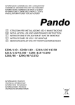
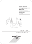
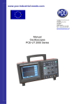
www.pce-industrial-needs.com Tursdale Technical Services Ltd Unit N12B Tursdale Business Park Co. Durham DH6 5PG United Kingdom Phone: +44 ( 0 ) 191 377 3398 Fax: +44 ( 0 ) 191 377 3357 [email protected] http://www.industrial-needs.com/ Manual Calibrator PCE-IC1 [email protected] 1. Safety Information .......................................................................................................... 3 1.1 warnings ........................................................................................................................... 3 1.2. Cautions .......................................................................................................................... 3 2. Introduction..................................................................................................................... 3 3. General Specifications ................................................................................................... 3 4. Environmental Conditions ............................................................................................. 4 5. Quick Start ...................................................................................................................... 4 5.1 Unpacking ........................................................................................................................ 4 5.2 Set Up ............................................................................................................................... 4 5.3 Setting the Temperature ................................................................................................. 5 6. Parts and Controls ......................................................................................................... 5 6.1 Back Panel ....................................................................................................................... 5 6.2 Front Panel ....................................................................................................................... 6 7. General Operation .......................................................................................................... 7 8. Controller Operation ...................................................................................................... 7 8.1 Well Temperature............................................................................................................. 7 8.2 Temperature Set-point .................................................................................................... 7 9. Maintenance .................................................................................................................... 8 2 [email protected] 1. Safety Information Use this instrument only as specified in this manual. Otherwise, the protection provided by the instrument may be impaired. Refer to the safety information in Warnings and Cautions. 1.1 warnings BURN HAZARD – DO NOT touch the IR target surface of the unit. The temperature of the IR target surface is the same as the actual temperature shown on the display. If the unit is set at350°C and the display reads350°C, the target surface is 350°C.The top sheet metal of the instrument may exhibit extreme temperatures for areas close to the IR target surface. DO NOT turn off the unit at temperatures higher than 100°C. This could create a hazardous situation. Turning of the instrument less than 60°C is recommended. DO NOT connect and operate this unit without a properly grounded, properly polarized power cord. HIGH VOLTAGE is used in the operation of this equipment. Severe injury or death may result if personnel fail to observe safety precautions. Before working inside the equipment, turn the power off and disconnect the power cord. Overhead clearance is required. DO NOT place this instrument under a cabinet or other structure. DO NOT use this unit in environments other than those listed in the user’s guide. DO NOT operate near flammable materials. Use of this instrument at HIGH TEMPERATURES for extended periods of time requires caution. Completely unattended high temperature operation is not recommended for safety reasons. 1.2. Cautions To avoid possible damage to the instrument, follow these guidelines. DO NOT plug the unit into 220V if the heater switches and fuse holder read 110V. This action will cause the fuses to blow and may damage the instrument. DO NOT use fluids to clean the target surface. DO NOT change the values of the calibration constants from the factory set values. The correct setting of these parameters is important to the safety and proper operation of the calibrator. 2. Introduction The BX-350 Mini Infrared Calibrator is mainly structured by 58mm diameter target assembly and dry-well temperature system controlled by microcomputer. External reference thermometer is a metal cone with good heat-conducting ability, on the surface of thermometer there is a oxide film with emissivity 0.95. The BX-350 Calibrator is applied a class-A PT100 as a sensor with a temperature control system and wind-cold device. The BX-350 calibrator has rapid heating and cooling function and is switch able / which can be used in different temperature unit calibration. The calibrations can be done over a range of 50°C to350°C .Temperature display and stability resolution is 0.1 degree. 3. General Specifications Range 50ºC to 350ºC Accuracy ± 0.5 ºC at 100 ºC ±1.0 ºC at 200 ºC ±1.5 ºC at 350 ºC Stability ±0.1 ºC at 100 ºC / ( ±0.2 ºF at 212 ºF) ±0.2 ºC at 200 ºC / ( ±0.4 ºF at 392 ºF) ±0.3 ºC at 350 ºC / ( ±0.6 ºF at 662 ºF) Target Emissivity Resolution / (122 ºF to 662 ºF) / / / ( ±1.2 ºF at 212 ºF) ( ±2.0 ºF at 392 ºF) ( ±3.0 ºF at 662 ºF) 95 1 ºC /0.1 ºF 3 [email protected] Heating Time Cooling Time Aperture Diameter Power Size Weight 0 minutes to max 0 minutes to 100 ºC (122 ºF) 58mm 20 VAC (±10%), 1.25 A / 110 VAC (±10%), 2.5 A 180x114x233 3kg 4. Environmental Conditions Although the instrument has been designed for optimum durability and trouble-free operation, it must be handled with care. The instrument should not be operated in an excessively dusty or dirty environment. Maintenance and cleaning recommendations can be found in the Maintenance section of this manual. The instrument operates safely under the following conditions: Verhältnis zwischen IR-Referenztemperatur delta T °C und tatsächlicher Abweichung (Delta T) 0 -0,1 -0,2 -0,3 -0,4 -0,5 -0,6 50 100 150 200 250 300 350 IR-Referenztemperatur °C Temperature range: 5-35°C (41-95°F) Ambient relative humidity: 15-80% Pressure: 75kPa – 106kPa Mains voltage within ±10% of nominal Vibrations in the calibration environment should be minimized 5. Quick Start 5.1 Unpacking Unpack the calibrator carefully and inspect it for any damage that may have occurred during hipment. If there is shipping damage, notify the carrier immediately. Verify that the following components are present: PCE-IC1 Calibrator Power Cord User’s Guide 5.2 Set Up Place the calibrator on a flat surface with at least 8 inches of free space around the instrument. The prop may be swung down to raise the front of the instrument from a horizontal position. Plug the power cord into grounded mains out let Note: this calibrator has two power specification of one model NO: 220V/AC and 110V/AC please make sure if the power value is suitable for the instrument before operation. 4 [email protected] Turn on the power to the calibrator by toggling the power switch on. The fan should begin quietly blowing air through the instrument and the controller display should illuminate after 3 seconds. After a brief self-test the controller should begin normal operation. If the unit fails to operate please check the power connection. The heater will start operating to bring the temperature of the calibrator to the set-point temperature and the display will begin to show the actual target temperature. 5.3 Setting the Temperature 1º Press "UP" or "DOWN” to change the set-point value. 2º Then press "SET", the calibrator will automatically control the target assembly temperature to reach the set temperature in the stated time. The red LED display will indicate the temperature of the target assembly. When the set-point temperature is changed the controller switches the well heater on or off to raise or lower the temperature. The displayed well temperature gradually changes until it reaches the set-point temperature. The well may require 5 to 10 minutes to reach the set-point depending on the span. Another 5 to 10 minutes is required to stabilize within ±0.1°C of the set-point. Ultimate stability may take 15 to 20 minutes more of stabilization time. 6. Parts and Controls The user should become familiar with the calibrator and its parts. 6.1 Back Panel FUSE FUSE ON OFF Fig 1. Back Panel Description The back panel (Figure 1) consists of the power cord inlet, power switch, heater voltage switch, and fan. 1. 2. 3. 4. 5. Wind input Fuse of Heather Fuse of temperature control system Power Input Power switch 5 [email protected] Power Inlet – At the rear of the calibrator is the removable power cord inlet that plugs into an IEC grounded socket. Caution: Do not plug the unit into 220V if the heater read 110V. This action will cause the fuses to blow and may damage the instrument. Fan – The fan inside the calibrator has two speeds and runs continuously when the unit is being operated to provide cooling for the instrument. The fan runs slow for heating and maintaining operation and runs fast for rapid cooling. Slots are provided for airflow. The area around the calibrator must be kept clear to allow adequate ventilation. The airflow is directed out the front and can be extremely hot. 6.2 Front Panel 5 AT OUT SET DOWN UP Fig 2.Front Panel Description The front panel (Figure 2) consists of the controller display, controller keypad, and target assembly. Controller Display 1. The red LED (the first line display) displays actual temperatures and settings for selected scale ºC or ºF. 2. The green LED (the second line) displays the set-point value and shows temperatures in units according to selected scale ºC or ºF. 3. The indicator of the operation state AT-Automotive parameter adjustment.(only used to factory for adjusted) OUT-The indicator of heat output with indication of the heating state of the target assembly ALM1-Overload alarm when the target assembly temperature 4 ºC higher than the set temperature, indicates the heating power off ALM2-Overload alarm. when the target assembly temperature 4 ºC higher than the set temperature, indicates the cooling with strong wind ºF - ºF temperature indicator ºC - ºC temperature indictor 4. Controller Keypad The four button keypad allows easy setting of the set-point temperature. The control buttons (SET, , DOWN, UP )are used to set the calibrator temperature set-point, Setting the control temperature is done directly in degrees of the current scale. The control temperature can be set to one-tenth of a degree Celsius or Fahrenheit. The keypad 6 [email protected] SET-The set button. This is used to confine setting temperature and select ºC or ºF. -The enter button .Which is used to select ºC or ºF. DOWN-The down button. Which is used to down setting temperature and change the unit ºC to ºF UP- The up button. Which is used to up setting temperature and change the unit ºF to ºC 5. Target assembly, The target assembly is 58mm in diameter and has an emissivity at 0.95 6. The test hole for temperature sensor of a good thermometer. 7. General Operation Place the calibrator on a flat surface with at least 8 inches of free space around the instruments. The front of the instrument is towards to user. 7.1 Connect the calibrator to the power supply, input proper voltage(110Vor 220V). 7.2 Turn on the instrument to "ON" button. 7.3 Changing Display Units The PCE-IC1 can display temperature in Celsius or Fahrenheit. The temperature units are shipped from the factory set to Celsius and locked. the unlock way is: Press the button of "SET" and “ ” at the same time. After unlock, first press "SET" button for three seconds, the first line red LED will display " ", the second line green LED will display " pt2"; release "SET" and press " ", the second line green LED will indicate the present temperature unit; press “DOWN” to ºF, press "UP" again to choose ºC the temperature unit letter will be flashing in the process of choosing the temperature unit. Then press” SET” to confirm green LED stop flashing press “SET” again the calibrator return to operation. In order to keep good operation, please lock the values after the temperature unit changed. The way is : Press “ ” button three times the first line red LED display“ ” the second line green LED display“ OFF ” at last press” SET” to complete the ” then press “UP” button two times green LED will display “ temperature unit change. 8. Controller Operation This chapter discusses in detail how to operate the instrument temperature controller using the front control panel. Using the front panel key-switches and LED display the user may monitor the well temperature, and the heater output power and adjust the controller proportional band. The control buttons (SET, DOWN, UP) are used to set the calibrator temperature set-point. 8.1 Well Temperature The digital LED display on the front panel allows direct viewing of the actual well temperature. This temperature value is normally shown on the display. The units, ºC or ºF, of the temperature value are displayed at the right. For example, 100.0 ºC Well temperature in 100.0 degree Celsius 8.2 Temperature Set-point The temperature set-point can be set to any value within the range and with resolution as given in the specifications. Be careful not to exceed the safe upper temperature limit of any device inserted into the well. Press "UP" to setup the higher temperature, or press "DOWN" to setup the lower temperature. Press the button every time the temperature will be changed 0.1 ºC or ºF, Press the button constantly the temperature will be changed 1 ºC or ºF every time. The front panel green LED display will indicate the actual set temperature. When the set temperature changes, the value are flashing. Release "UP" or "DOWN" and then press "SET", the calibrator will automatically control the target assembly. Temperature to reach the set temperature in the stated time. The red LED display will indicate the temperature of the target assembly. 8.3 Reduce the temperature 7 [email protected] below 100 ºC after measurement , when the temperature is reduced below 100 ºC the user can turn off the power. warning: turning off the power at high temperature will be easy to destroy the calibrator , which should be cooled off by fan. 9. Maintenance The calibration instrument has been designed with the utmost care. Ease of operation and simplicity of maintenance have been a central theme in the product development. Therefore, with proper care the instrument should require very little maintenance. Avoid operating the instrument in dirty or dusty environments. If the outside of the instrument becomes soiled, it may be wiped clean with a damp cloth and mild detergent. Do not use harsh chemicals on the surface, which may damage the paint. The calibrator should be handled with care. Avoid knocking or dropping the calibrator. If the instrument is used in a manner not in accordance with the equipment design, the operation of the instrument may be impaired or safety hazards may arise. In this direction will find a vision of the measurement technique: http://www.industrial-needs.com/measuring-instruments.htm NOTE: "This instrument doesn’t have ATEX protection, so it should not be used in potentially explosive atmospheres (powder, flammable gases). 8