1
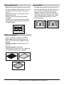
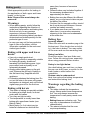
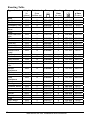
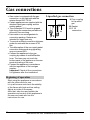
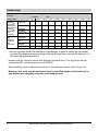
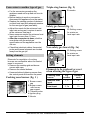
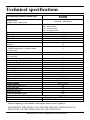
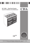
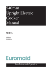
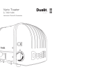
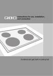
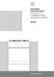
BT2355SS and BT2365SS
Freestanding combined cooker
User Manual
Freestanding combined cooker
Dear Customer!
Congratulations on your purchase. See
for yourself: our products read reliability.
These ample instructions have been
compiled in order to help you learn how
to handle the appliance. They will show
you step by step what your appliance is
capable of, so please read them carefully
before you attempt to use your cooker for
the first time.
Safety warnings are listed on page 4.
The first thing to do is to check if your
appliance has arrived undamaged. In
case you find any transport damages,
please report it immediately to your local
dealer, or to the regional warehouse
which supplied the appliance. You will
find their phone numbers on the invoice
or on the delivery note.
We hope your cooker will successfully
serve its purpose for many years.
Contents
Safety precautions .......................................... 4
Intended use
If you notice any malfunction in the gas
installation, or if you smell gas in the room:
Electric ignition
Prior first use.................................................. 8
Oven
Gas cooking zones
Gas burner control......................................... 9
Safety cautions in regard to the cooking
zones
Ignition and operation of burners
Cookware
Oven .............................................................. 12
Important warnings!
Operation
Modes of operation
Oven guide levels
Oven accessories
Grease filter
Baking pastry
Roasting
Grilling and browning (barbecue)
Preserving of fruit and vegetables
Defrosting
Cleaning and maintenance...........................22
Gas cooking zones
Oven
Oven drawer
Troubleshooting guide..................................25
Note!
Important!
Replacement of parts....................................26
Other accessories
Oven light bulb
Instructions for installation and connection27
Safety precautions for the technician
Safety precautions
Anti Tilt Bracket
Leveling the appliance and extra support
Manufacturer's adjustments
Gas connections.............................................30
Beginning of operation
Installation Requirements and Regulations
REGULATIONS
Nozzle chart
Conversion to another type of gas
Setting elements
Electrical connections...................................34
Technical specifications................................35
Instructions for use, installation and connection
3
Safety precautions
x To avoid any possible hazard, the
appliance may be installed by qualified
personnel only, authorized by the gas
distributing company and by the
authorized service. Installation should
be carried out in accordance with the
legal regulations and technical
requirements of the local gas supplier.
Important instructions in this regard
may be found in the Section
"Instructions for installation".
x Any repairs by unqualified persons may
result in explosion, electric shock or short
circuit. In order to avoid possible injuries
to your body or to the appliance, do not
attempt any repairs by yourself. Such
work should be carried out by qualified
service personnel.
x Before installing and connecting the
appliance check whether the
specifications of the local gas supplier
(type of gas and pressure) correspond to
the specifications of the appliance.
x Technical specifications of the appliance
are indicated on the rating plate.
x This appliance is not connected to a
chimney or vent opening. The appliance
must be installed and connected in
accordance with the standing regulations.
Special attention should be taken in
regard to adequate ventilation.
x During the operation of gas burners the
room may be filled with extra heat and
humidity, so it is necessary to assure
adequate ventilation. Occasional opening
of the window or door should provide
enough exchange of air. During the
prolonged use of the appliance, or during
a very intense use, more ventilation will
be required, and it will probably be
necessary to engage the extractor hood.
x Hot grease is highly inflammable, so pay
extra attention when preparing food with
grease or oil. Frying may be carried out
only under constant surveillance.
4
x Never clean the oven or the cooktop with
hot steam devices or high-pressure jet
cleaning device, as they may provoke
short circuit.
x Before opening the control panel and
before any attempted repairs disconnect
the appliance from the mains.
x Do not keep any flammable material in
the drawer under the oven (paper, wiping
cloth, plastic bags, cleaning agents or
sprays, etc.), as they might cause fire.
Use the drawer to keep only the oven
utensils (flat baking pan, oil collector, oil
filter, etc.).
x Mains lead of adjacent appliances may
be damaged by cooking zones or if stuck
between the oven doors, and produce
short circuit, therefore keep them at safe
distance from the appliance.
x Never use the burners or the oven for
heating of the room. Never place empty
dishes upon the cooking zones.
x Pay special attention to the precise
assembly of burner components.
x Never put aluminum foil to the bottom of
the oven, and do not place any crockery
upon the bottom of the oven, since it may
impede the air circulation, so the oven
enamel may be damaged by the
excessive heat.
x Warning: do not let small children in the
vicinity of the cooker; they are not yet
aware of danger of burns. Older children
may use the appliance only under your
surveillance.
x Surface of cooking zones and oven door
may become very hot during operation.
The inside of the oven, cooking zones
and steam exits are also places of
potential danger for children, so keep the
at adequate distance.
x Danger of burns: cooking zones, oven
and cooking accessories may become
very hot during operation. To avoid burns
use kitchen clothes and gloves when
handling hot parts or utensils.
Instructions for use, installation and connection
x Door hinges may be damaged if the open
door is charged with heavy objects. Do
not sit on the door and never put any
heavy loads on the door in the open
position.
x Rating plate with basic information about
the appliance, and the gas type sticker,
are located inside the oven and are
accessible when the oven door is
opened.
x The appliance is classified Class 2/1.
When positioned in a row it may be
located between two adjacent kitchen
elements on both sides. On one side it is
permitted to install a high kitchen cabinet,
higher than the appliance at a distance of
not less than 30 cm.
x The distance between the appliance and
the kitchen hood must be at least 650
mm, or not less than the distance,
indicated in the instructions for use of the
kitchen hood installation.
If you notice any malfunction in the
gas installation, or if you smell gas
in the room:
x immediately shut off the gas inlet or close
the gas tank;
x extinguish any open flames and tobacco
products;
x you may not switch on any electric
appliances (neither turn on the lights!);
x open all windows and provide thorough
air circulation!
x immediately notify the service center or
your authorized gas supplier.
The symbol on the product or on
its packaging indicates that this
product may not be treated as
household waste. Instead it shall
be handed over to the applicable
collection point for the recycling of
electrical and electronic equipment.
By ensuring this product is disposed
of correctly, you will help prevent
potential negative consequences for
the environment and human health,
which could otherwise be caused by
inappropriate waste handling of
thisproduct. For more detailed
information about recycling of this
product, please contact your local city
office, your household waste disposal
service or the shop where you
purchased the product.
Intended use
This gas cooker is intended for traditional
use in your household. Never use the
appliance for any other purpose!
Instructions for use, installation and connection
5
Description of the appliance
This is the description of cooker with
electric oven and three gas burners and
one electric hotplate. Depending on the
model, the hob can also be equipped
with four gas burners or two gas burners
and two electric hotplates.
Steam exit
Cooktop
Control panel
Oven door handle
Oven glass door
Drawer
Additional support (certain models
only)
Adjustable legs (certain models only)
- accessible after removing the
drawer
Steam exit
Cooktop
Control panel
Oven door handle
Oven glass door
Drawer
Additional support (certain models
only)
Adjustable legs (certain models only)
- accessible after removing the
drawer
6
Instructions for use, installation and connection
1
1
2
3
4
5
6
7
8
9
3 4 2
5
6
7
8
9
1 Timer
2 G as ignition button (certain models
only).
3 Oven ON/OFF button and function
mode selection.
4 Oven signal light. On when the oven is
heated, and off when the set
temperature is reached.
5 Oven temperature selection button
Electric ignition
(certain models only)
Gas burners may be ignited with the
electric ignition device, built-in adjacent
to each burner.
6 Cooking zone, rear left, normal burner
7 Cooking zone, front left, normal burner
8 Cooking zone, front right, double
burner
9 Cooking zone, rear right, auxiliary
burner
Electric ignition will operate only if the
mains lead is plugged into the mains
socket.
In case of electric failure or damp ignition
device, the cooktop burners may be
ignited with a simple match or lighter.
Instructions for use, installation and connection
7
Prior first use
Oven
Take all the accessories out of the oven
and clean it with warm water and your
usual mild detergent. Never use
aggressive cleaners as they might cause
scratches!
During the first heating the oven might
produce a somewhat unpleasant smell of
a new product. This is normal, just
ventilate the place thoroughly!
Gas cooking zones
There are no special measures to be
taken prior first use of gas cooking
zones.
8
Instructions for use, installation and connection
Gas burner control
Cooking burners are controlled by the
relevant control knobs. Heating power is
indicated on the knobs by the large
flame symbol and the small flame
symbol.
Always turn the knob over the large
flame position towards the small flame
position and back. The operating position
is always between the two flame
symbols.
Safety cautions in regard to the
cooking zones
x Never use cooking zones without dishes,
or for heating the ambience!
x Keep the cooktop clean, since dirt and
stains have adversary effect on the
functionality of burners.
x If you like your food to be crisp, first set
the burner to the maximum and continue
cooking at minimum power.
x Always provide adequate quantity of
water when cooking in the pressure
cooker. Lack of water may cause
damage to the dish and to the cooker.
x Cooktop burners are thermally
protected. If the burner flame is
accidentally extinguished (spilled
food, gust of wind) the gas supply is
automatically shut. There is no
possibility of gas escaping into the
room!
x If the flame of thermally non-protected
cooking burners is accidentally
extinguished, the gas escapes into the
room!
x Be very precise when placing the burner
crown cap upon the crown. Always keep
the crown nozzles clean and free.
Instructions for use, installation and connection
crown cap
thermal
coupling
(certain models
only)
ceratin models
only
burner crown
correct
position of
burner
components
9
Ignition and operation of burners
Gas burners may be ignited by means of
electric ignition spark plug, fitted
adjacent to each burner (certain models
only).
Single handed ignition
(certain models only)
To ignite the burner, press the selected
burner button and turn it to the maximum
power position . Electric spark from the
ignition device ignites the gas.
If the ignition device is out of order, either
due to power failure or humid ignition
device, use a match or a lighter to ignite
the gas.
flame is not stabilized and may be
extinguished.
x If the flame goes out repeat the
procedure.
x If the burner flame goes out (for whatever
reason), shut the burner off and wait for
at least one minute before next attempt.
x Note: before igniting the burners (triplering burner, double-ring burner, and Mini
Wok) cover them with appropriate
cookware.
x To shut the burner off turn the button to
the right, to the OFF position
(CLOSED).
Gas faucet is closed
Maximum power position
Minimum power position
Ignition with both hands
(certain models only)
To ignite the burner, press the selected
burner button and turn it to the maximum
power position . Now press the ignition
device button. Electric spark from the
ignition device ignites the gas.
If the ignition device is out of order, either
due to power failure or humid ignition
device, use a match or a lighter to ignite
the gas.
To facilitate positioning small dishes on
the burner grid, place the attached
support extension over the auxiliary
burner.
x Keep the button pressed for
approximately 10 seconds after ignition to
stabilize the flame.
x If you failed to ignite the burner after 15
seconds, shut the burner off and wait for
at least one minute before the next
attempt.
x After that you can set the burning power
between high and low position to suit
your cooking requirements.
x Button positions between
in
are
not recommended. In these positions the
10
Instructions for use, installation and connection
Cookware
Selection of the adequate dish size
ensures optimized cooking time and
consumption of gas. Diameter of the dish
is of utmost importance.
The flame reaching over the edge of the
small diameter dish may destroy the
dish, while the consumption of gas is
increased.
Gas needs oxigen for burning. In case of
excessively large dish diameter the
oxigen supply is insufficient,
consequently reducing the burning
capacity.
The wire grid
The wire grid is used for dishes with
small diameter. Place the grid over the
auxiliary burner crown.
Burner type
Large (3,0kW)
Normal (1,9kW)
Auxiliary (1,0kW)
Triple-ring (3,5kW)
Dish diameter
220-260 mm
180-220 mm
120-180 mm
220-260 mm
Instructions for use, installation and connection
11
Oven
Important warnings!
x Never put aluminum foil to the bottom of
the oven, and do not place any crockery
upon it. The oven enamel may be
damaged by the excessive heat.
x Fruit juice, dripping from the baking pan,
may produce stains upon the enamel,
which are very hard to remove.
Operation
During all other oven functions the
illumination is automatically switched on
with the selection of a particular function.
Some models have installed two lamps
for oven lighting; one at the top of rear
wall and the second one at the middle of
right-handed side wall .
Applying upper and
lower heater
Heaters from the upper and the lower
side uniformly heat the exposed food.
Baking and roasting is possible only at
single level.
Oven is
controlled by
the function
knob and the
temperature
selection knob.
Temperature selection knob
Grill
Function knob (Please, take into
consideration the knob of your
appliance)
Heat comes directly from the infrared
heater, located at the oven ceiling. It is
especially suitable for preparing steaks,
sausages, T-bones, pork chops, etc.
Modes of operation
Oven may be used in the following
modes.
Oven illumination
Oven illumination may be switched on
independently, without any other
function.
This may come handy during the
cleaning, or when switched off and using
the remaining oven heat.
12
Instructions for use, installation and connection
Grill with ventilator
Defrosting
Infrared heater and ventilator operate
simultaneously. This mode is appropriate
for roasting and grill of larger chunks of
meat or poultry at one level. It may also
be used to obtain crisp skin on your
roast.
This is the mode with air, circulating
without any of the heaters being turned
on. It is used for slow defrosting of food.
Lower heater and
ventilator
Both the lower heater and hot air
ventilator are in operation. This mode is
most appropriate for baking pizza. It may
also be used for baking moist or heavy
cake at two levels, fruit cake or cheese
souffle.
Ventilator with hot air
The fan at the rear forces the air around
the roast or pastry. It is suitable for
roasting and baking at more than one
level.
Lower heater and
ventilator
Both the lower heater and ventilator are in
operation. The mode is useful for baking
low pastry and preparation of preserved
fruit and vegetables.
Use the first guide level from the bottom,
and not too high pans, to allow the air to
circulate along the upper side of the food.
Applying lower
heater/Aqua clean
Heat is applied only by the bottom side of
the oven. Use this option for browning
the bottom side of the food (baking
heavy, moist pastry with fruit dressing).
The temperature selection button in such
cases may be selected as required.
Lower heater may also be used for the
cleaning of oven. You will find details in
the section Cleaning and maintenance.
Instructions for use, installation and connection
13
Oven guide levels
Grease filter
Baking pans and accessories (oven grid,
grease receptacle, baking tray, etc.) may
be inserted into the oven in 5 guiding
levels.
Appropriate levels are indicated in the
tables that follow.
Always count levels from the bottom
upwards!
In case of wire guides, the grid and the
baking pans must always be inserted in
the guide slides.
Inserted grease filter at the rear panel of
the oven protects the fan, the heater and
the oven from accidental staining with
grease. Always insert the filter when
roasting or grilling, and remove the filter
when baking pastry. Grease filter might
cause unsuccessful baking of some
kinds of pastry.
Oven accessories
(differ according to different models)
Oven grid shelf for placing pans and
trays, or for food to be prepared using
the grill.
Flat biscuit tray for baking cake and
biscuits.
Dripping grease receptacle
(deep tray) for moist cake, for roasting or
for intercepting dripping oil/grease.
14
Instructions for use, installation and connection
Baking pastry
Most appropriate position for baking is
the application of both upper and lower
heater, or the hot air.
Note! Grease filter must always be
removed!
Warnings
x When baking pastry, strictly follow the
instructions regarding the selection of
guide level, temperature and baking time,
and do not rely on any previous
experience, because information
indicated in the baking tables have been
determined and tested specially for this
particular type of oven.
x In case you may not find any particular
type of cake in the tables, use the
information available for the next most
similar type of cake.
Baking with upper and lower
heater
x Use only a single guide level.
x This baking position is especially suitable
for baking dry pastry, bread and
teacakes.Use dark baking pans. Light
pans reflect heat and pastry is not
adequately browned.
x Always place baking pans on the grid
rack. Remove the grid only if baking in
the flat biscuit tray, supplied with the
appliance.
x Preheating shortens the baking time. Do
not put the cake in the oven until proper
temperature is obtained, and until the red
signal lamp goes off for the first time.
Baking with hot air
x This mode of baking is especially suitable
for baking at multiple levels, for moist
pastry and fruit cakes.
x You may use light models.
x The temperature is usually lower than
baking with upper/lower heater (see
Baking Table).
x Moist pastry (i.e. fruit cake) may be
baked at maximum two levels at the
same time, because of excessive
humidity.
x Different cakes may be baked together if
the necessary temperature is
approximately the same.
x Baking time may be different for different
pastry, so you may have to take one pan
out before the others.
x Cookies, like for example muffins, should
be of equal size and thickness. Uneven
cookies are baked unevenly.
x If you bake more than one cake at the
same time, it may produce excessive
steaming in the oven and condensation
at the oven door.
Baking tips
Is pastry baked?
Pierce the cake with a wooden peg at the
thickest part. If the dough does not stick
to it, the cake is baked. You may switch
off the oven and use the remaining heat.
Pastry has fallen
Check the recipe. Use less fluids next
time. Follow the mixing times, especially
when using powered kitchen mixers.
Pastry is too light below
Use dark baking pan next time, or place
the pan one level lower, or switch on the
lower heater a while before the
completion.
Cheese cake is undercooked
Next time reduce the baking temperature
and extend the baking time.
Warnings regarding the baking
tables:
x The tables indicate the temperature
range. Always select lower temperature
first. You may always increase the
temperature in case pastry needs more
baking.
x Baking times are indicative only. They
may vary in dependence of individual
characteristics.
x The asterix indicates that the oven
requires preheating.
Instructions for use, installation and connection
15
Pastry Baking Table
Type of pastry
Sweet pastry
Raisin cake
Ring cake
Tree cake (tart form)
Cheese cake (tart form)
Fruit cake
Fruit cake with icing
Sponge cake*
Flake cake
Fruit cake, mix dough
Cherrycake
Jelly roll*
Fruit flan
Plait bun
Cristmass cake
Apple pie
Puff paste
Salted pastry
Bacon roll
Pizza*
Bread
Rolls*
Cookies
Caraway roll
Biscuits
Danish pastry
Flaky pastry
Cream puff
Deep frozen pastry
Apple pie, cheese pie
Cheese cake
Pizza
Chips for oven*
Potato fries for oven
16
Guide level
(from down
upwards)
Temp.
(°C)
Guide level
(from down
upwards)
Temp.
(°C)
Baking
time
(in min.)
2
2
2
2
2
2
2
3
3
3
3
3
2
2
2
2
160-170
160-170
160-170
170-180
180-190
170-180
170-180
180-190
170-180
180-200
180-190
160-170
180-200
170-180
180-200
170-180
2
2
2
3
3
3
2
3
3
3
3
3
3
3
3
3
150-160
150-160
150-160
150-160
160-170
160-170
150-160
160-170
150-160
150-160
160-170
150-160
160-170
150-160
170-180
150-160
55-70
60-70
45-60
60-80
50-70
60-70
30-40
25-35
50-70
30-50
15-25
25-35
35-50
45-70
40-60
40-60
2
2
2
2
180-190
210-230
190-210
200-220
3
3
3
3
170-180
190-210
170-180
180-190
45-60
30-45
50-60
30-40
3
3
3
3
3
170-180
170-180
180-200
190-200
180-200
3
3
3
3
3
150-160
150-160
170-180
170-180
180-190
15-25
20-30
20-35
20-30
25-45
2
2
2
2
2
180-200
180-190
200-220
200-220
200-220
3
3
3
3
3
170-180
160-170
170-180
170-180
170-180
50-70
65-85
20-30
20-35
20-35
Instructions for use, installation and connection
Roasting
Best results are obtained with the
engagement of both upper and lower, or
with hot air.
Best heating mode for each type of
roasting pan is indicated by bold print in
the Roasting Tables.
Note! When roasting always insert the
grease filter!
x When roasting on the grill grid, place the
grid in the deep roasting pan and insert
both into the sliding guide. The bottom
pan will intercept dripping fat.
x Never leave roast to cool in the oven, as
it might produce dew and corrosion of the
oven.
Tips regarding roasting pans
x Use light enamel pans, temperature
resistant glass pans, clay dishes or
wrought iron dishes.
x Stainless steel dishes are not
recommendable because they
excessively reflect heat.
x Cover your roast or wrap it in foil. It will
preserve its juice and the oven will
remain cleaner.
x If you leave the pan uncovered, the roast
will be cooked sooner. Roast large
chunks of meat directly on the grid, with
intercepting pan underneath.
Attention when roasting!
Roasting tables indicate suggested
temperatures, guide level and roasting
times. Roasting time largely depends
upon the type of meat, its size and
quality, so you may expect some
variations.
x Roasting of large chunks of meat may
produce excessive steaming and dew
formation at the oven door. This is quite
normal, and does not affect the operation
of the oven. However, after the
completion of roasting wipe the oven
door and the glass thoroughly.
x Roasting of red meat, poultry and fish is
rational if the roast exceeds one kilogram
in size.
x Add as much liquid as necessary to
prevent burning of juice, dripping from
meat. Roast must be surveyed at all
times, and liquid added if necessary.
x At approximately the middle of the
indicated time turn the roast round,
especially if you use the deep roast dish.
Instructions for use, installation and connection
17
Roasting Table
Type of meat
Beef
Beef loin
Beef loin
Roastbeef, rare
Roastbeef, well
done
Pork
Pork roast with
skin
Flank
Flank
Pork loin
Meat roll
Pork cutlet
Minced meat
roast
Veal
Veal roll
Veal knuckle
Lamb
Lamb prime
ribs
Mutton
bladebone
Venison
Hare ribs
Hare
bladebone
Boar ham
Poultry
Chicken, entire
Hen
Duck
Goose
Turkey
Fish
Fish, entire
Fish souffle
18
Weight
(in
grams)
Guide level
(from
bottom up)
Temp.
(°C)
Roasting
time
(in min.)
Temp.
(°C)
Roastin
g time
(in min.)
1000
1500
1000
1000
2
2
2
2
200 -220
200-220
220-230
220-230
2
2
2
2
180-190
170-180
180-200
180-200
100-120
120-150
30-40
40-50
1500
2
180-190
2
170-180
140-160
1500
2000
1500
1500
1500
1500
2
2
2
2
2
2
190-200
180-200
200-220
200-220
180-200
210-220
2
2
2
2
2
2
170-180
160-170
160-170
160-170
160-170
170-180
120-150
150-180
120-140
120-140
100-120
60-70
1500
1700
2
2
180-200
180-200
2
2
170-190
170-180
90-120
120-130
1500
2
190-200
2
170-180
100-120
1500
2
190-200
2
170-180
120-130
1500
1500
2
2
190-210
190-210
2
2
180-190
170-180
100-120
100-120
1500
2
190-210
2
170-180
100-120
1200
1500
1700
4000
5000
2
2
2
2
2
200-210
200-210
180-200
160-170
150-160
2
2
2
2
2
180-190
180-190
160-170
150-160
140-150
60-70
70-90
120-150
180-200
180-240
1000
1500
2
2
200-210
180-200
2
2
170-180
150-170
50-60
50-70
Instructions for use, installation and connection
Grilling and browning (barbecue)
x Take extra precautions when grilling.
Intensive heat from infrared heater
makes the oven and the accessories
extremely hot. Use protective gloves
and barbecue accessories!
x Perforated roast may produce
spurting of hot grease (sausages).
Use long grill tongs to prevent skin
burns and protect your eyes.
x Supervise the grill at all times.
Excessive heat may quickly burn your
roast and provoke fire!
x Do not let the children in the vicinity of
the grill.
Grill heater is especially suitable for the
preparation of low-fat sausages, meat
and fish fillets and steaks, and for
browning and crisping the roast skin.
Tips for grilling
x Grilling should be carried out with the
oven door closed.
x Grilling tables indicate the recommended
temperature, guide levels and grilling
times, which may vary according to the
weight and quality of meat.
x Always insert the grease filter when
grilling.
x Grill heater should be pre-heated for 3
minutes.
x Oil the grill grid before placing the food,
otherwise food might stick to the grid.
x Place the meat upon the grid, then place
the grid upon the grease interception
pan. Insert both trays into the oven
guides.
x Turn the meat round after half of the
roasting time has expired. Thinner slices
will require only one turn, for larger
chunks you might need to repeat the
procedure. Always use barbecue tongs to
avoid losing excessive juice from meat.
x Dark beef meat is grilled quicker than
lighter pork or veal.
x Clean the grill, the oven and the
accessories each time after use.
Instructions for use, installation and connection
19
Grill table
Type of meat for
grill
Meat and sausages
2 beefsteaks, rare
2 beefsteaks,
medium
2 beefsteaks, well
done
2 pork scrag fillets
2 pork chops
2 veal staeks
4 lamb cutlets
4 grill sausages
2 slices of meat
cheese
1 chicken, halved
Fish
Salmon fillets
Fish in aluminium foil
Toast
4 slices of white
bread
2 slices of wholemeal
Toast sandwich
Meat/poultry
Duck
Chicken
Pork roast
Pork scrag
Pork knuckle
Roastbeef/beef fillet
20
Weight
(in
grams)
Guide level
(from bottom
up)
Temp.
(°C)
Temp.
(°C)
Grill time
(in min.)
400
400
5
5
250
250
-
7-9
10-14
400
5
250
-
16-20
350
400
700
700
400
400
5
5
5
5
5
5
240
240
240
240
240
240
-
18-20
18-20
16-20
10-14
8-12
7-10
1400
3
-
400
500
4
4
240
-
220
8-12
10-13
200
5
240
-
1-2
200
600
5
5
240
240
-
1-2.5
1.5-3
2000
1000
1500
1500
1000
1500
1
3
3
3
3
3
-
150-170
160-170
140-160
140-160
140-160
170-180
80-100
60-70
90-120
100-180
120-160
40-80
210-220 28-33 (1. side)
23-28 (2. side)
Instructions for use, installation and connection
Preserving of fruit and vegetables
Use the bottom heater mode together
.
with the fan
x Prepare food for preserving and the jars
in a usual manner Use the conventional
jars with glass cover and rubber gasket.
Never use jars with threaded or tin
covers, or tins. Jars should be of the
same size, filled with the same type of
food and well tightened. You may place
up to six one-liter jars.
x Use only fresh groceries.
x Pour around one liter of water into the
deep roasting pan, to produce the
required humidity. Place the jars into the
oven without touching the oven walls
(see fig.). Cover the jars with a wet paper
to protect the rubber gaskets.
x Insert the pan with jars into the second
guide from bottom up. Set the
temperature regulation knob to 180qC.
Pre-heating of oven is not necessary.
x Watch the jars all the time. Once the
liquid in the jars starts boiling, follow the
instructions from the Preserving Table.
Preserving table
Type of
Quantity
fruit or
vegetables
Bottom heaterand
°
fan, 180 C, until
After boiling
Cooling time
boiling
Fruit
Strawberry
6x1 liter
around 30 min
switch off
15 min
Drupes
6x1 liter
around 30 min
switch off
30 min
Stewed
f it
Vegetable
Pickles
6x1 liter
around 40 min
switch off
35 min
6x1 liter
30 to 40 min
switch off
Beans,
carrots
6x1 liter
30 to 40 min
Defrosting
Defrosting of food may be accelerated by
circulating air within the oven. To do this,
set the oven to the position "Defrost" .
Note! In case of accidental engagement
of the temperature regulation knob the
red light switches on, but no heater is
active.
30 min
°
reduce to 130 C
60 - 90 min
30 min
x You may defrost frozen cream cake or
butter cream cake, other biscuits and
pastry, bread and rolls, as well as deep
frozen fruit.
x For reasons of hygiene do not defrost
meat and poultry in the oven.
x If possible, stir the food or turn it over for
better and more uniform defrosting.
Instructions for use, installation and connection
21
Cleaning and maintenance
Never clean the appliance with
pressurized hot steam cleaner!
Before cleaning switch the cooker off and
let it cool down completely.
Front side of the casing
For cleaning of frontal part of the cooker
use the usual cleaning agents and follow
the manufacturer's instructions.
Never use any aggressive cleaning
agents or dish cleaning accessories
which might cause scratches.
Stainless steel front
Clean the surface with mild detergent
(soap) and soft sponge which does not
scratch. Never use aggressive cleaners
or solvents, otherwise you may damage
the surface.
Enamel coated and plastic
surfaces
Clean the knobs and handles with soft
cloth and liquid cleaners, intended for
use of smooth enamel surfaces.
Gas cooking zones
Gas grid, cooking area and burner
components should be cleaned with
warm water and mild detergent for
manual washing of dishes.
Thermal element and ignition device
should be cleaned with soft brush. To
ensure perfect operation, these elements
must always be thoroughly clean.
Clean the crown and the crown cap. Always
keep the gas outlet nozzles on the burner
crown free of dirt.
Upon completion of cleaning wipe all
components dry and replace them
carefully to their respective slots.
Oblique position of components may
cause troubled ignition of burners.
22
Note! Crown caps are coated with black
enamel. Discoloration of caps, due to
high temperatures, is inevitable, but it
has no adversary effect on normal
operation of burners.
Oven
The oven may be cleaned in a traditional
mode (using oven cleaners and sprays).
The following procedure is
recommended for regular cleaning of the
oven (after each use):
Turn the mode selection button to the
position
. Set the temperature control
button of the cold oven to 50°C. Pour 0,4
l of water into the baking pan and insert it
into the bottom grid lead. After thirty
minutes the food residues upon the
enamel coating are softened, and may
be easily wiped off with a moist cloth.
Otherwise respect the following cleaning
tips:
x Cool the oven completely before
cleaning.
x The oven and the accessories must be
cleaned after each use, otherwise stains
might get burned in.
x Oven walls, sprayed with oil from
roasting, is best cleaned with warm water
and detergent when the oven is still tepid.
x Hard and heavily stained oven should be
cleaned with special oven cleaning
agents. Rinse the cleaner thoroughly and
Instructions for use, installation and connection
remove any detergent remaining before
the next use.
x Never use aggressive cleaners, like
polishing agents, dish cleaning
accessories, corrosion inhibitors, or any
other devices that might cause scratches.
x Coated, stainless steel or zinc-coated
surfaces or aluminum parts must not
come into contact with oven sprays, since
they might cause damage or
discoloration. The same goes for
thermostat probe (if the cooker is
equipped with it) and exposed heaters on
the oven ceiling.
x When purchasing cleaning agents
remember the environment, and strictly
follow the manufacturer's instructions.
Removing wire guide grids
Wire guides may be removed to facilitate
the cleaning of the oven. Side grids are
removed by swinging the bottom side
inwards and unhooking them from their
place.
Clean the side grids only with
conventional detergents.
To reinsert, repeat the procedure
backwards: slide them into the holes
and swing downwards.
Instructions for use, installation and connection
23
Removing oven door with a
single axe hinge
Open the door completely and turn the
removable locks backwards (see fig).
Then close the door slowly and let the
locks fit to the notches. At an angle of
about 15q lift the door slightly up and pull
the door from the hinge supports (fig. 2).
For reinserting the door repeat the
procedure backwards. Insert the door at
an angle of about 15q into the hinge
supports by pushing them forward and
downwards, so the hinges lock into their
slots (fig. 3). Check if the hinges are
locked into their respective slots.
Now open the door completely and turn
the removable locks into their original
position. Close the door slowly and
check if they close properly (fig. 4). If you
have trouble closing the door, check if
the hinges are properly inserted into their
slots.
Attention! Never let the hinge locks
spring out, as the springs are strong and
may cause injuries.
special enamel, with smooth and
resistant surface.
This special coating facilitates cleaning
at room temperature.
Grease filter
Clean the grease filter after each use
with soft brush in hot water with some
detergent, or wash it in the dishwasher.
Before placing it in the dishwasher the
grease on the filter must be softened in
water.
Oven drawer
x The oven drawer is protected from
accidental opening.
x It may be open by lifting upwards. To
remove the drawer from the cooker pull it
out to the limit, then lift upwards and pull
out completely.
x Never place any flammable or explosive
substances in the drawer.
x The drawer is equipped with side slides
on wheels. To insert it back, slide the
wheels into the slide guides and push
inwards
Accessories
Accessories, like biscuit tray, oven grid,
etc. are cleaned with hot water and the
usual detergent.
Special enamel
Oven, interior door lining, baking tray and
grease interception pan are coated with
24
Instructions for use, installation and connection
Troubleshooting guide
Any unskilled attempt to repair the
appliance is extremely dangerous as it
might cause electric shock and short
circuit. To avoid such injuries any repairs
may be performed only by qualified
personnel, or after sales service.
Before attempting any repairs disconnect
the appliance from the mains by
removing the fuse or unplugging the
mains lead from the mains socket.
Note!
There are, however, some minor faults
which may be easily removed by the
user, in accordance with the instructions
that follow.
Important!
If the malfunction of the appliance was
caused by the improper use, the service
visit during the warranty period is not
free of charge.
Following are some simple advice
how to repair minor faults:
Signal lamp does not turn on....
x are all the required switches properly
activated?
x is the mains power fuse burned?
x is the temperature regulator properly set?
Fuses often burn out...
x Call the serviceman or your electrician!
Oven illumination is not on....
x Exchange of oven bulb is described in
the section "Replacement of parts".
Oven does not heat up...
x is the mains power fuse burned?
x is the temperature regulator set
correctly?
Baking results are
disappointing...
x did you remove the grease filter?
x did you follow the instructions and
warnings from the section "Baking"?
x did you strictly follow the information from
the Baking table?
Burners do not burn
uniformly…
x Gas serviceman should check the gas
settings!
Burner flame suddenly changes,
burners require excessive
ignition time…
x Assembly the burner components
correctly!
Flame goes off immediately
after ignition…
x Keep the button pressed somewhat
longer.
x Push firmly once more before releasing
the button.
Burner grid has changed color
in the burning area…
x This is a normal consequence of high
temperature; clean the grid with metal
cleaner.
Electric ignition of gas is
malfunctioning, burner covers
are dirty…
x Carefully clean the gap between the
ignition spark and the burner.
x Clean the covers with a metal cleaning
agent.
Instructions for use, installation and connection
25
Replacement of parts
The oven light bulb casing is under
tension. Danger of electric shock!
Before replacing the oven bulb switch off
the cooker and cut it from mains by
removing the mains power fuse or
disconnect the protective device.
Remember that the bulb is regarded as
consumption material and is not covered
by the warranty.
Other accessories
Oven grid, biscuit tray, etc. may be
ordered from the service center. When
ordering please quote the code and the
type or model of the appliance.
Hotplate control knobs are removed by
pulling them outwards and replaced by
pushing the new ones back in place.
Oven light bulb
The bulb for replacement should meet
the following specifications:
E 14, 230 V, 25 W, 300°C.
Unscrew the glass
cover by turning it counter clockwise, and
replace the bulb. Screw the glass cover
back in place.
Remember that the bulb is regarded
as consumption material and is not
covered by the warranty.
26
Instructions for use, installation and connection
Instructions for installation and
connection
Safety precautions for the
technician
Installation may be carried out in
accordance with the standing
regulations. It is extremely important to
ensure adequate air circulation.
Safety precautions
x Connections must be carried out only
by the expert personnel, authorized by
the gas distribution company.
x Provide regular air circulation in the room
where the appliance is located.
x Gas arrangements are specified on the
sticker adjacent to the rating plate.
x Before connecting the appliance check
that the local connection requirements
(gas pressure and type) match the
features of the appliance.
x The appliance may not be connected to
the fumes exhaust device (for example to
the chimney). It must be located and
installed in accordance with the standing
installation and connection regulations.
Special attention should be devoted to
the ventilation requirements.
x Distance between the cooktop and the
kitchen hood must be at least the
distance, indicated in the instructions for
use of the kitchen extraction hood.
x The appliance is classified Class 2/1.
When positioned in a row it may be
located adjacent to a high kitchen
cabinet. Horizontal distance to high
cabinet or to the wall must be at least 300
mm.On the other side it is permitted to
have only the cabinet of equal height as
the appliance. Suspended cabinets may
be installed at such height as not to
impede the cooking process.
Minimum vertical distance from the
appliance must be at least 650 mm.
x In case the gas specifications do not
correspond to the requirements of the
appliance, call the service center or
the gas supplier. Qualified technician
will make necessary amendments to
agree with your type of gas.
x Any other amendments or replacements
requiring tools, may be performed by
qualified personnel only.
x In any case, you are allowed to replace
only such parts which do not require any
tools for their replacement!
x Panels, glue and furniture lining from
artificial materials, adjacent to the
appliance must be temperature resistant
(>90°C), otherwise they might be
deformed.
x Mains lead behind the cooker must be
placed in such manner to avoid touching
the back panel of the cooker because of
the heat it develops during operation.
x Remove any packaging materials (foils,
artificial foam, nails, etc.) from the reach
of children, because they represent
potential danger. Children may swallow
small parts, or suffocate with foils.
Instructions for use, installation and connection
27
Anti Tilt Bracket
Leveling the appliance and extra
support
Your appliance is equipped with extra
support. The height of the cooker with
the support is 90 cm, and without support
it is 85 cm. Left and right side of the
support is equipped with two wheels to
facilitate relocation. In the front part, on
both sides there are two adjustable
screws, used to level the cooker and
adjust its upper edge in line with the
adjacent kitchen furniture.
Adjustable legs are accessible when the
drawer is pulled out. Adjust the position
of the cooker by turning the legs in one
direction or another. Adjustable legs will
be turned easier if the appliance is
somewhat lifted up and tilted.
Additional support may be removed by
unscrewing the four screws holding it to
the bottom of the cooker. In such case
relocate the adjustable screws from the
support and place them left and right at
the bottom front base of the cooker.
Level the cooker as described earlier.
Some cookers are equipped with four
adjusting screws (two in front and two at
the back), used for leveling the appliance
or adjusting its heights to match the
adjacent furniture.
28
Instructions for use, installation and connection
Manufacturer's adjustments
Gas cookers are tested and equipped
with the symbol CE.
Gas cookers are supplied sealed and
adjusted to natural gas H or E (20 mbar)
or to liquid gas (50 or 30 mbar).
Specifications are indicated on the rating
plate, located in the interior of the oven
and accessible when the oven door is
opened.
Gas load and consumption of particular
burners are indicated in the table below.
Modification to another type of gas
requires the exchange of gas nozzles.
Information are indicated in the table
below.
In case of damage or broken seal the
functional components of the cooker
must be rechecked and resealed in
accordance with the instructions for
installation.
Such functional components are: fixed
nozzle for large flame and adjustable
nozzle for small flame.
Instructions for use, installation and connection
29
Gas connections
x Gas cooker is equipped with the gas
connection on the right side with the
exterior thread ISO 7-R1/2.
x Certain appliances are supplied with the
attached liquid gas coupling and the
sealing gasket.
x The connection R1/2 must be gripped
tight during the connection procedure to
prevent it from revolving.
x Use metal or non metal gaskets for
connection packing. Gaskets are
intended for single use only.
x To provide sufficient connection tightness
screw the nuts with the moment of 30
Nm.
x The deformation of the non-metal gasket
connection thickness during tightening
may not exceed 25%.
x Connect the appliance to the gas
coupling by means of certified flexible
hose. The hose may not touch the
bottom panel of the appliance or the rear
panel and ceiling of the oven.
x Connect the appliance in accordance
with the regulations of the local gas
supplier.
Important! Check all the connections
for tightness after the installation!
Liquefied gas connection
Beginning of operation
Start using the appliance in accordance
with the instructions for use.
Lit up all burners and check the stability
of the flame with high and low setting.
Adjust air intake if necessary.
After that, take time and explain the
operation and control of the appliance to
the user and read with him the
instructions for use.
30
Instructions for use, installation and connection
9 Pipe coupling
for liquefied
gas
10 Gasket
11 R 1/2
connection
Installation Requirements and Regulations
This appliance must be installed by a competent person in accordance with the current
versions of the following UK
(United Kingdom) or ROI (Republic of Ireland) Regulations and Safety Standards or their
European Norm Replacements.
NOTE: UK law stipulates that gas appliances must be installed and repaired by a
CORGI. Registered Installer (all Baumatic
Engineers are CORGI Registered).
REGULATIONS
Gas Safety Regulations (Insallation & Use).
Building Regulations (issued by the Department of Environment).
Iris Standard for Domestic Gas Installations.
Building Standards (issued by the Scottish Development).
IEE Wiring Regulations
Electricity at Work Regulations.
BS 6172 Installation of Domestic Cooking Appliances (if necessary, BS 5482
Installation of Domestic LPG Appliances).
BS 5386 Pt 4 Built-in Domestic Cooking Appliances.
BS 5440 Installation of Flues and Ventilation for Gas Appliances.
Baumatic Ltd Installation Instructions.
Instructions for use, installation and connection
31
Nozzle chart
Type of gas,
pressure
Wobe number
Natural gas H
Wo=45,7y
54,7 MJ/ m3,
Natural gas E ,
Natural gas E+
Wo=40,9y
54,7 MJ/m3
G20,
p=20mbar
Liquid gas 3+,
3B/P
Wo=72,9y
87,3MJ/m3
G30
p=30 mbar
Auxiliary burner
Nominal heat
input (kW)
Consumption (l/h)
Nozzle mark
(1/100mm)
Nozzle code
Nominal heat
input (kW)
Consumption
(g/h)
Nozzle mark
(1/100mm)
Nozzle code
Standard
max
min
1
0,36
Normal burner
Large burner
Triple burner
Fast
max
1
min
0,36
max
1,90
min
0,46
max
3
min
0,76
max
3,5
min
1,56
148,5
95,21
34,4
95,21
34,4
180,9
43,8
285,64
72,4
333,2
77
-
78
-
104
-
129
-
140
162081
162082
1
0,36
1
71,7
26,2
50
29/24
162162
162083
0,36
1,90
71,7
26,2
50
29/24
162162
162084
0,46
3
138,1
33,4
69
33/26
162164
x
162085
0,76
3,5
215,0
55,3
254,5
113,4
87
43/33
93
57/57
162165
1,56
162166
x Built-in regulation knobs are intended for liquefied gas. In case of natural gas (municipal
gas line) they need to be set according to the required gas flow (unscrew for maximum 1,5
turn from the tightened position).
Nozzle code for minimum varies with different manufacturers. First digit from the pair
represents IMIT, and the second one COPRECI.
Burner heating input is indicated according to the maximum caloric value of gas Hs.
Warning: this work may be performed only by qualified expert, authorized by the
gas distribution company or by the authorized service!
32
Instructions for use, installation and connection
Conversion to another type of gas
x For the conversion procedure the
appliance need not be pulled out from its
location.
x Before starting to work on conversion,
disconnect the appliance from the mains.
x Replace the existing nozzles of declared
nominal heat input with adequate nozzles
for the new type of gas (see table).
x Adjust the nozzle for the minimum heat
input rate as long as it requires to arrive
at the minimum heat input.
x Never unscrew nozzles for minimum heat
input rate for more than 1,5 turn.
x After the conversion is done, stick the
new sticker with the actual gas
specifications of the appliance over the
old one.
x Check that electrical cables, thermostat
probe and thermal elements are located
away from the gas jet!
Triple-ring burner (fig. 2)
5 nozzles
Safety gas faucet (fig. 3)
13 Setting screw
for minimum
heat input rate
Non-safety gas faucet (fig. 3a)
13 Setting screw
for minimum
heat input rate
Setting elements
Elements for regulation of cooking
burners are accessible when the control
panel is removed.
x Remove the cooktop grid and burner
crowns with caps.
x Remove the control buttons.
x Unscrew bottom tightening screws from
the control panel and remove the panel.
Cooking zone burner (fig. 1 )
1
1 Burner crown
cap
2 Burner crown
with burner
cap support
3 Thermal probe
4 Ignition plug
5 Nozzle
Elements to be replaced or reset
when altering the type of gas
Cooking zone
burner
Nominal heat
input
Minimum
heat input
Fig.
number
1, 2
Element
code
5
3, 3a
13
Instructions for use, installation and connection
33
Electrical connections
Open the connection box using
the screwdriver, as shown by the
drawing on the cover.
Connection to the mains power can be
done only by the authorized service
center or by qualified personnel!
Wrong connection may damage the
parts of appliance and render your
warranty viod!
Connecting voltage of the user’s
installation (230 V against N) must be
verified by qualified electrician using the
appropriate tester.
Connector bridges must be positioned
in accordance with the installation
connection!
x Prior connecting the appliance, check
whether the voltage of the rating plate
corresponds to the actual voltage of
home installation.
x Length of the power lead must be at least
1.5 m so that the appliance can be
connected to power before pushing it
against the wall.
x Length of the earthing lead must be
longer than the others, so that it is
strained later than the tension power
leads in case of accidental pullout from
the socket.
Procedure
If the relief device has not been fixed yet,
fix it in such way to hook the power cable
to the device housing at one end.
x Now connect the power cable in
accordance to one of the options shown
on the figure. In case of different
installation voltages, the connection
bridges should be rearranged
accordingly!
x Tighten the relief device and close the
connection box cover.
NOTE:
In some connection boxes the connector
bridges are placed between contacts 4
and 5, and in the others they are stored
at a designated place within the box.
These boxes have the connection screws
already in open position so they need not
be unscrewed. During the tightening
procedure you will hear a faint “click”,
meaning that the tightening screw should
be fastened tightly all the way.
Colored power leads
L1, L2, L3 = exterior power leads under
tension. Usual colors are black, black,
brown.
N = neutral lead
Usual color is blue.
Watch for the correct N-connection!
x Using the screwdriver open the
connection box cover at the back of the
PE = earthing (protective lead)
appliance. You can do so by releasing
two catches, as shown on the connection
Lead color is green-yellow.
box cover.
x Power cable must be guided through the
relief device, protecting it from pulling out.
34
Instructions for use, installation and connection
Technical specifications
Freestanding combined cooker type
Dimensions
height / width / depth (cm)
Gas burners *
BT2355SS
BT2365SS
85/60/60 - 90/85-60/60
D = Triple-ring burner
B = large burner
A = normal burner
H = auxiliary burner
Rear left
1,9/A
Front left
1,9/A
Front right
3,0/B
Rear right
1,0/H
Oven
Temperature selector / Oven function mode
1/1
selector
Baking levels
5
- telescopis guides at 3 levels (certain
models only)
Upper /lower heater (kW)
0,9/1,1
Infrared heater/ Infrared heater
2,0/2,2
with fan (kW)
Oven illumination top/side (W)
25/25
Modes of operation
Upper /lower heater (kW)
2,0
Grill heater (kW)
2,0
Grill with fan (kW)
2,0
Hot air / lower heater (kW)
3,4
Hot air (kW)
2,2
Defrost (W)
50
Lower heater / fan (kW)
1,1
Lower heater (kW)
1,1
275 °C
Max. temperature
400 V 2N~, 50 Hz
Mains voltage
230 V, 50 Hz
Heater voltage
Total mains power (kW)
5,4
Oven total (kW)
3,4
Hotplates total (kW)
Burners total (kW)
7,8
567
Total mains power (g/h)
Gas specifications are indicated on the label adjacent to the rating plate.
ISO 7- R1/2
Gas mains connection (right)
Group
GB, IE,GR = II2H3+
*Burner capacity is calculated for the higher caloric value of gas Hs.
WE RESERVE THE RIGHT TO ALTER THE SPECIFICATIONS WITH NO
INFLUENCE ON THE OPERATION OF THE APPLIANCE.
Instructions for use, installation and connection
35
Baumatic Ltd. Conditions of guarantee
Dear Customer,
Your new Baumatic appliance comes complete with a free 12 month guarantee covering both parts and
labour costs resulting from defective materials or workmanship.
Baumatic also gives you the opportunity to automatically extend the guarantee period for a further 12
months at no extra cost, giving an initial guarantee period of 24 months. The extended guarantee period
applies to England, Scotland, Wales and Northern Ireland only.
To qualify for your full 24 months guarantee you must register your appliance within 28 days of purchase
to be covered under this guarantee. This can be done online via: www.baumatic.co.uk or through returning
the guarantee card which can be found in each new Baumatic appliance.
* In addition, your appliance is covered by a 5 year parts warranty. Baumatic Ltd will provide free of
charge the parts required to repair the appliance, only if they are fitted by a Baumatic engineer, for any
defect that arises due to faulty materials or workmanship within a period of 5 years from the original
purchase date.
* An additional 1 to 3 year insurance scheme for labour is available should you wish to extend the
warranty period.
Should any person other than an authorised representative of Baumatic Ltd interfere with the appliance, the
policy is negated and Baumatic Ltd will be under no further liability.
The guarantee covers the appliance for normal domestic use only, unless otherwise stated.
Any claims made under the terms of the guarantee must be supported by the original invoice/bill of sale
issued at the time of purchase.
This guarantee is transferable only with the written consent of Baumatic Ltd.
If the appliance fails and is considered either not repairable or uneconomical to repair between 12 months
(2 years if registered) and five years, a free of charge replacement will not be offered.
The guarantee for any replacement will only be for the remainder of the guarantee on the original product
purchased.
The guarantee does not cover:
- Sinks and taps
- Failure to comply with the manufacturers instructions for use.
- The replacement of cosmetic components of accessories
- Accidental damage or wilful abuse.
- Subsequent loss or damage owing to the failure of the appliance or electrical supply
- Incorrect installation
- Losses caused by Acts of God, civil war, failure to obtain spare parts, strikes or lockouts
- Filters, fuses, light bulbs, external hoses, damage to bodywork, paintwork, plastic items, covers,
baskets, trays, shelves, burner bases, burner caps, decals, corrosion, rubber seals.
In the course of the work carried out it may be necessary to remove the appliance from it operating
position. Whilst all reasonable care will be taken, Baumatic Ltd cannot accept responsibility for damage
sustained to any property whatsoever in this process.
This guarantee is in addition to and does not diminish your statutory or legal rights.
Contacting Baumatic Ltd
Sales
Service
Spares
TEL: 0118 933 6900
TEL: 0118 933 6911
TEL: 0118 933 6922
FAX: 0118 931 0035
FAX: 0118 986 9124
FAX: 0118 933 6942
For ROI (Republic of Ireland), please contact one of the numbers below:
TEL: 01 – 6266798
FAX: 01 - 6266634
Technical/Advice
0118 933 6933
0118 933 6942
Thanks you for buying Baumatic.
* Applies to UK, Scotland, Wales & Northern Ireland only (Republic of Ireland has 1 year labour & 1 year parts warranty only)
167083/en (09-06)