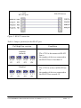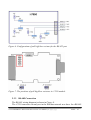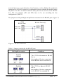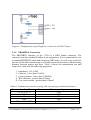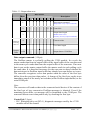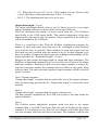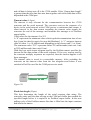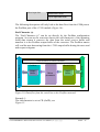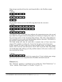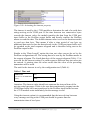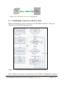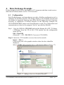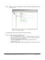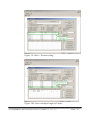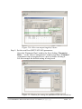
1
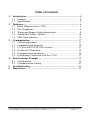
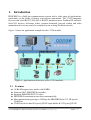
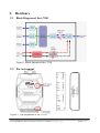
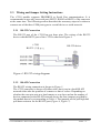
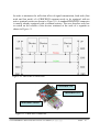
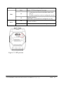
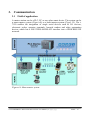
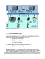
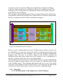
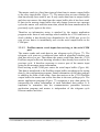
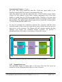
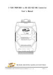
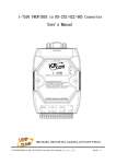
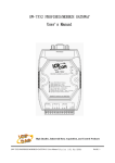
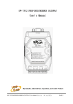
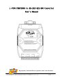
i-7550 PROFIBUS to RSRS-232/422/485 Converter
User's Manual
High Quality, Industrial Data Acquisition, and Control Products
i-7550 PROFIBUS to RS-232/422/485 Converter User Manual (Version 1.2)
PAGE:1
Warranty
All products manufactured by ICP DAS are under warranty regarding
defective materials for a period of one year from the date of delivery to the
original purchaser.
Warning
ICP DAS assumes no liability for damages resulting from the use of
this product. ICP DAS reserves the right to change this manual at any time
without notice. The information furnished by ICP DAS is believed to be
accurate and reliable. However, no responsibility is assumed by ICP DAS
for its use, or for any infringements of patents or other right of third parties
resulting from its use.
Copyright
Copyright by ICP DAS. All rights are reserved.
Trademark
The names used for identification only may be registered trademarks
of their respective companies.
List of Revision
Author
Raiden
Version
1.2
Revision
Release
i-7550 PROFIBUS to RS-232/422/485 Converter User Manual (Version 1.2)
PAGE:2
Table of Contents
1. Introduction…………………………………………………………. 4
1.1 Features………………………………………………………… 4
1.2 Specification…………………………………………………… 5
2. Hardware…………………………………………………………… 6
2.1 Block Diagram of the i-7550………………………………….. 6
2.2 Pin Assignment………………………………………………… 6
2.3 Wiring and Jumper Setting Instructions…………………….
8
2.4 Setting the Profibus Address………………………………… 14
2.5 LED status indicator…………………………………………. 15
3. Communication……………………………………………………. 17
3.1 Field of application…………………………………………… 17
3.2 Communication Sequence…………………………………… 18
3.3 i-7550 in a RS232/422/485 network…………………………. 21
3.4 Profibus I/O Data Area………………………………………. 22
3.5 Communication parameters…………………………………. 28
3.6 Establishing Connection with the i-7550……………………. 37
4. Data Exchange Example…………………………………………... 39
4.1 Configuration. ……………………………………………….. 39
4.2 Communication Testing……………………………………… 43
5. Troubleshooting…………………………………………………….51
6. Dimensions………………………………………………………… 52
i-7550 PROFIBUS to RS-232/422/485 Converter User Manual (Version 1.2)
PAGE:3
1.
Introduction
PROFIBUS is a field bus communication system with a wide range of applications,
particularly in the fields of factory and process automation. The i-7550 integrates
devices with serial RS-232, RS-485 or RS-422 interfaces into a Profibus DP network.
Serial I/O devices, electronic scales, operator terminals, barcode readers and other
automation devices can easily be connected to an existing Profibus network.
Figure 1 shows an application example for the i-7550 module.
Figure 1: Application architecture of the i-7550 modules
1.1
●
●
●
●
●
●
Features
16-Bit Microprocessor inside with 80MHz
Siemens SPC3 PROFIBUS controller
Supports PROFIBUS DP-V0 slave
PROFIBUS transmission rate detect automatically
Max transmission speed up to 12M bps for PROFIBUS and 115.2K bps for
COM Port
COM Port driver has 1K bytes QUEUE input buffer & 512 bytes QUEUE
i-7550 PROFIBUS to RS-232/422/485 Converter User Manual (Version 1.2)
PAGE:4
●
●
●
●
●
●
●
1.2
output buffer
Max length of in/output data is 128 Bytes
Built-in self-tuner ASIC controller on RS-422/485 port
2500Vrms High Speed iCoupler Isolation Protection for PROFIBUS network
3000VDC Isolation Protection on the PROFIBUS side
Provide LED indicators
Built-in Watchdog
Mountable on DIN Rail
Specification
COM Port specs:
● Serial port - RS-232/RS-422/RS-485
● Serial port interface: 14-pin screw terminal block
● Baud Rate:1200/2400/4800/9600/19200/38400/57600/115200 bps
● Data Format: 7/8 data bits, None/Odd/Even parity bit, 1 stop bit
PROFIBUS specs:
● PROFIBUS interface connector: D-sub 9-pin female
● Baud Rate: 9.6K/19.2K/45.45K/93.75K/187.5K/500K/1.5M/3M/6M/ 12Mbps
● Address Setting: 0~126 (set by DIP switch or EEPROM)
Power requirement:
● Unregulated +10V ~ +30V DC
● Power reverse protection, Over-Voltage brown-out protection
● Power consumption 2.5W
Module specs:
● Dimensions: 119mm X 72mm X 33mm
● Operating temperature: -25 ~ 75 ºC
● Storage temperature: -30 ~ 85 ºC
● Humidity:5 ~ 95%, non-condensing
● LED Status Indicators (Table 1)
Table 1: LED status indicator
−
−
ERR LED −
RUN LED −
PWR LED
Shows the power state
COM Port state: transmit or receive data
Show error state
Show communication state of PROFIBUS
i-7550 PROFIBUS to RS-232/422/485 Converter User Manual (Version 1.2)
PAGE:5
2.
Hardware
2.1 Block Diagram of the i-7550
RS-485
DRIVE
Figure 2: Block diagram of the i-7550
2.2
Pin Assignment
Figure 3: Pin assignment of the i-7550
i-7550 PROFIBUS to RS-232/422/485 Converter User Manual (Version 1.2)
PAGE:6
Table 2: 14-pin screw terminal block
Pin
Name
Description
1
D+
Data+ of RS-485
2
D-
Data- of RS-485
3
-
4
TX+
Transmit Data+ of RS-422
5
TX-
Transmit Data- of RS-422
6
RX+
Receive Data+ of RS-422
7
RX-
Receive Data- of RS-422
8
-
9
RX
Receive Data of RS-232
10
TX
Transmit Data of RS-232
11
GND
12
-
13
+VS
V+ of Power Supply(+10 to +30VDC)
14
GND
GND of Power Supply
N/A
N/A
GND of RS-232
N/A
Table 3: PROFIBUS DB9 Female Connector
Pin
Name
Description
1
-
N/A
2
-
N/A
3
B
Non-inverting Bus Line
4
ISODE
5
GND
6
VP
7
-
N/A
8
A
Inverting Bus Line
9
-
N/A
Isolated DE output for use in PROFIBUS
applications where the state of the isolated drive
enable node needs to be monitored.
Power supply ground for the first node and the last
node
+5V Power Supply for the first node and the last
node
i-7550 PROFIBUS to RS-232/422/485 Converter User Manual (Version 1.2)
PAGE:7
2.3 Wiring and Jumper Setting Instructions
The i-7550 module supports PROFIBUS to Serial Port communication. It is
recommended to use only one serial port (RS232, RS485 or RS422) of the converter
at the same time. The following section describes the necessary steps to be taken to
connect one of the three COM port types to a serial device or serial network.
2.3.1 RS-232 Connection
The RS-232 port of the i-7550 has got three pins. The wiring of the RS-232
device with the RS232 port of the i-7550 is shown in Figure 4.
i-7550
RS-232 COM port
RS-232 device
Figure 4: RS-232 wiring diagram
2.3.2 RS-422 Connection
The RS-422 wiring connection is shown in Figure 5.
The i-7550 converter is always a Profibus slave but it can in a local RS-422
network either take the position of a master or that of a slave. Depending on
whether the converter acts as a local master or as a slave and on the number of
devices connected to the RS-422 network device the four jumpers provided by
the module has to be set according to Table 4. The jumpers set the pull high and
pull down resistors for the RS-422 port (Figure 6, Figure 7).
i-7550 PROFIBUS to RS-232/422/485 Converter User Manual (Version 1.2)
PAGE:8
i-7550
RS-422 port
RS-422 device
Figure 5: RS-422 connection
Table 4: Jumper position for the RS-422 port
Pull high/low resistor
Enabled
(default)
Disabled
Condition
− The i-7550 is the master in RS-422
bus or
− the number of devices connected to
the RS-422 bus is less than 10
− The i-7550 is a slave in RS-422 bus
or
− the number of devices connected to
the RS-422 bus exceeds 10
i-7550 PROFIBUS to RS-232/422/485 Converter User Manual (Version 1.2)
PAGE:9
Figure 6: Configuration of pull high/low resistor for the RS-422 port
Figure 7: The positions of pull high/low resistors in i-7550 module
2.3.3 RS-485 Connection
The RS-485 wiring diagram is shown in Figure 8.
The i-7550 converter can only act in the Profibus network as a slave. In a RS-485
i-7550 PROFIBUS to RS-232/422/485 Converter User Manual (Version 1.2)
PAGE:10
network however it can either be a local master or slave. Before the module is
connected to a RS-485 network it is important to know whether the module takes
the place of a slave or master and how many devices are active on the RS-485
bus. The two jumpers (JP1 and JP2) have to be set according the bus
configuration (Table 5).
The jumpers set the pull high and pull down resistors for the RS-485 port (Figure 9).
i-7550
RS-485 Port
RS-485 Device(s)
Figure 8: RS-485 connection
Table 5: Jumper position for the RS-485 port
Pull high/low resistor
Condition
Enabled
(default)
− The i-7550 is the master in RS-485
bus or
− the number of devices connected
to the RS-485 bus is less than 10
Disabled
− The i-7550 is a slave in RS-485
bus or
− the number of devices connected
to the RS-485 bus exceeds 10
i-7550 PROFIBUS to RS-232/422/485 Converter User Manual (Version 1.2)
PAGE:11
Figure 9: Configuration of pull high/low resistor for the RS-485 port
2.3.4 PROFIBUS Connection
The PROFIBUS interface of the i-7550 is a DB9 female connector. The
connector uses the standard Profibus 9 pin assignment. It is recommended to use
a standard PROFIBUS cable and connector (DB9 male). As with every serial bus
the rate of safe data transmission in a Profibus network decreases with increasing
distance between master and slave. Table 6 shows the transmission rate and
range for a cable with the following properties:
1.
2.
3.
4.
5.
Impedance :135~165Ω
Capacity : lower than 30 pF/m
Loop resistance : lower than 110Ω/Km
Wire diameter : greater than 0.65mm
Core cross-section : greater than 0.34mm2
Table 6: Transmission rate decreasing with increasing transmission distance
Transmission Rate(Kbps)
9.6; 19.2; 93.75
187.5
500
1500
3000; 6000; 12000
Transmission Distance per Segment (meter)
1200
1000
400
200
100
i-7550 PROFIBUS to RS-232/422/485 Converter User Manual (Version 1.2)
PAGE:12
In order to minimize the reflection effect of signal transmission, both ends (first
node and last node) of a PROFIBUS segment needs to be equipped with an
active terminal resistor as shown in Figure 10. A standard PROFIBUS connector
is usually already equipped with a terminal resistor. The user therefore only has
to switch on the resistor of the devices stationed at the ends of a segment as
shown in Figure 11.
Figure 10: PROFIBUS connection
Terminator ON
Terminator OFF
Terminator Switch
Figure 11: PROFIBUS connector
i-7550 PROFIBUS to RS-232/422/485 Converter User Manual (Version 1.2)
PAGE:13
The number of stations in a Profibus network is restricted to 126. According to
the PROFIBUS specification up to 32 stations are allowed per segment. A
repeater has to be used to link the bus segments.
2.4 Setting the Profibus Address
The station address of i-7550 can be set by using either the dip switch or by
writing it directly to the EEPROM. The dip switch covers a range from 0 to 255.
The valid address range of a Profibus station spans from 0 to 126. Table 7 shows
three examples of setting the station address by using the dip switch. The dip
switches are accessed by opening the modules housing, Figure 22. Table
explains which address will be used by the module after power on, if the dip
switch address setting differs from the address stored in the EEPROM.
Table 7: Dip switch setting example
DIP SWITCH(SW1)
Station address
1
2
3
4
5
6
7
8
1
1
0
0
0
0
0
0
0
10
0
1
0
1
0
0
0
0
126
0
1
1
1
1
1
1
0
Table 8: The Address setting of the i-7550
Dip Switch Setting
0~125
126-254
255
Description
1. The address setting of the EEPROM is
ignored.
2. The address can not be set by the PROFIBUS
configuration tool.
1. The address setting of the dip switch is
ignored.
2. If the address in the EEPROM is 126, the
PROFIBUS configuration tool can set a new
address and save it to the EEPROM.
1. Slave address in the EEPROM is set to 126.
i-7550 PROFIBUS to RS-232/422/485 Converter User Manual (Version 1.2)
PAGE:14
Figure 22: DIP switch
Each slave must have a unique valid address (1 to 125) in order to be able to
communicate with the master. To change the address by using the configuration
tool it is necessary to first set the address stored in the EEPROM to 126. This is
done by setting the dip switch to 255 in the power off state. Switching the
module on is forcing the module to change its address in the EEROM to 126. In
the next step switch the module off and change the dip switch setting to any
value from 126 to 254. This step is necessary in order to prevent the module to
change its address in the EEPROM to 126 every time it is powered on. The
configuration tool can now assign the slave a new address.
2.5 LED status indicator
The i-7550 provides three LEDs to indicate the statuses of the i-7550 module.
The position of LEDs and descriptions are shown in Table 9 and Figure 33.
Table 9: LED status description
LED Name
Status
flash
PWR
Description
Power supply is ok.
COM Port is transmitting or receiving data.
on
Power supply is ok.
The firmware has loaded.
off
Power supply has failed.
i-7550 PROFIBUS to RS-232/422/485 Converter User Manual (Version 1.2)
PAGE:15
LED Name
Status
flash
ERR
RUN
Description
Error! I-7550 has diagnostic message.
on
− Connection error between Profibus master and
slave or
− Profibus system has not been configured correctly.
off
Normal operation
PROFIBUS system has been configured correctly
on
Data exchange mode
Normal operation.
off
i-7550 module is not in a data exchange mode.
Figure 33: LED position
i-7550 PROFIBUS to RS-232/422/485 Converter User Manual (Version 1.2)
PAGE:16
3. Communication
3.1
Field of application
A master station can be a PLC, PC or any other smart device. The system can be
a mono-master system (Figure 44) or a multi-master system (Figure 55). The i7550 enables the integration of single serial devices such as I/O devices,
electronic scales, operator terminals, barcode readers and other automation
devices which has a RS-232/RS-485/RS-422 interface into a PROFIBUS DP
network.
Figure 44: Mono-master system
i-7550 PROFIBUS to RS-232/422/485 Converter User Manual (Version 1.2)
PAGE:17
Figure 55: Multi-master system
3.2 Communication Sequence
To fully understand the i-7550 field of applications, its strength and limitation it
is important to understand the way in which data is processed by the converter.
Basically the converter has got four buffers (Figure 66):
− Profibus slave input buffer
− Profibus slave output buffer
− COM port input buffer
− COM port output buffer
The Profibus master has basically got two buffers (Figure 77):
− Profibus master input buffer
− Profibus master output buffer
During each message cycle the master writes the content of its output buffer to
the slaves input buffer and reads the content of the slave output buffer to its input
buffer. This data exchange cycle is taken place in a regular time interval and
i-7550 PROFIBUS to RS-232/422/485 Converter User Manual (Version 1.2)
PAGE:18
irrespective of the converters COM port communication. This data exchange
cycle in a fixed time interval is a distinctive feature of a Profibus network. The
exchange cycle is taking place even though the content of the master and slave
output buffer has not changed.
The way data is transferred from the COM port input buffer to the Profibus slave
output buffer and from the Profibus slave input buffer to COM port output buffer
has to be configured by the Profibus configuration program.
Profibus:
Output
Buffer
Serial:
Micro
processor
Input
Buffer
Input
Buffer
Serial Network
Profibus Network
i-7550 Profibus to Serial Converter:
Output
Buffer
Figure 66: Data flow in the converter
Before a cyclic communication between a Profibus master and the converter can
be established it is required to specify the number of input and output bytes that
are to be exchanged in each telegram cycle with the Profibus configuration
program. Once the slave is an active station in the Profibus network the
configured input and output length can not be changed. A new configuration of
the slave is only possible when it is in an off-line mode.
If for example the converter receives from a RS232 device a greater data package
than the configured output length it will only transfer the configured data length
to the Profibus master. The remaining data packet will not be sent. That means
irrelevant of the amount of data received by the i-7550 converter the data length
transmitted to the Profibus master is always limited by configured length.
3.2.1 Data Flow
3.2.1.1 Profibus master send output to the serial COM port
i-7550 PROFIBUS to RS-232/422/485 Converter User Manual (Version 1.2)
PAGE:19
The master sends in a fixed time interval data from its master output buffer
to the slave input buffer (Figure 77). The master does not care whether the
data has already been send or not. It only reads data from its output buffer
and does not remove the data from the output buffer after it has been send.
If data in the masters input buffer does not change between two message
cycles the master will send the same data, which has been transferred in the
previously cycle, again to the slave.
Therefore an information string is attached by the master application
program at the front of each message which enables the i-7550 converter to
check whether it has already been dispatched to the COM port or not. In
case of new data it is immediately sent via the serial output buffer to the
COM port.
3.2.1.2
Profibus master reads input data arriving at the serial COM
port
The master sends and reads data in one telegram cycle (Figure 77). The
telegram cycle starts at a configured time interval regardless whether new
data has arrived or not. That means the master reads data from the i-7550
Profibus output buffer not knowing whether it has already been read in the
previous cycle. It therefore necessary to reserve part of the master input
string for the message status information.
Data arriving at the COM port enters the serial input buffer (Figure 66).
This data is transferred to the Profibus output buffer according to the setting
done by the configuration program. Status information of this data package
is added to the front of the string. Once data arrives at the i-7550 Profibus
output buffer the master can access this data in the next polling cycle. The
master application program (Figure 77) recognizes a new data packet by
interpreting the status information of each individual data packet. It is
important to remember that the communication procedure between
application program and master is independent of the telegram cycle
between master and slave.
i-7550 PROFIBUS to RS-232/422/485 Converter User Manual (Version 1.2)
PAGE:20
Profibus Master:
Network
Master Application
Programm:
Input
Buffer
Read
Program sends
data to the
Master
Output
Buffer
Write
Profibus
Data is
transferred on a
program call
i-7550 Profibus Part:
Profibus:
Output
Buffer
Input
Buffer
Figure 77: Data flow between application program and converter
3.3 i-7550 in a RS232/422/485 network
Chapter 0 mentions that the converter can either take the position of a local
master or that of a slave in the serial network (Figure 88) it is connected to. In
the Profibus network the i-7550 always remains a slave Profibus slave and can
not be used as a Profibus master.
3.3.1 Local Serial Master
A master in a serial network is the only device which can initiate a request. The
slaves are passive and are only allowed to response to a request. If the
converter acts as a master in the serial network it has the right to send a request
to a slave. The original request has been send by the profibus master
application program and the converter just passes it on. The profibus master
application program therefore acts as a master to the local serial network. The
response from the slave is transferred to the Profibus output buffer of the
converter. In the following polling cycle the Profibus master reads the response
data.
3.3.2 Local Serial Slave
In this case the converter is the passive device in the serial network and is only
allowed to send data when a request has been specifically addressed to it. As
this converter can not be assigned an address, every message transferred in the
i-7550 PROFIBUS to RS-232/422/485 Converter User Manual (Version 1.2)
PAGE:21
local serial network will be read by the converter and forwarded to the Profibus
master. It is the master application program which has to process the data and
take the place of a serial slave. The master application program acting as a
slave therefore should only response to telegram addressed to it.
Notice:
All the data transfer in the serial network is recorded by the module and
consequently read by the Profibus master.
PLC
Profibus DP
i-7550
Profibus slave
RS422
or
RS485 network
Figure 88: Integrating a serial network to a Profibus network
3.4 Profibus I/O Data Area
The Profibus master sends and receives data in one telegram cycle. That is, the
master sends output data to the slave (i-7550 module) and receives input data
from the slave in a single cycle. The maximum length for each input and output
data is 128 bytes.
i-7550 PROFIBUS to RS-232/422/485 Converter User Manual (Version 1.2)
PAGE:22
3.4.1 Input Data Area
The first three bytes of the received input data are reserved for the
communication status.
The first byte indicates the transmission status. The second shows the length of
the data transferred from the COM port input buffer to the Profibus output
buffer of the converter. The third byte represents a transmission counter.
The remaining data in the input data area represents the data packet received
from the serial network. The fourth byte therefore shows the first byte of the
received serial data.
Table 10: Input data area
Byte
1
Message
property
Input
Data
Data
Description
0x00
i-7550 is currently not transmitting I/O data
0x01
i-7550 is transmitting data to the COM Port
0x02
i-7550 is receiving data :
Data received by the COM Port input buffer is
transferred to the Profibus output buffer
2
Length Received data length
3
Counter Receive data count
4~128
Data
Receive data from COM Port
Data Length (2. byte):
It is important to notice that this value does not show the length of the data
package read by the Profibus master but the length of the data package
transferred from the COM port input buffer to the Profibus output buffer of the
converter. If the image of the input data (Profibus master input length) set by
the configuration tool is equal or greater than the transferred length then the
length of both data packages are identical. In case the image of the input data is
smaller than the length of the data package transferred from the COM port
input buffer then the Profibus master will only read the number of bytes set by
the configuration tool. The master therefore does not receive all the data sent
by the serial network. It lies in the responsibility of the system administrator to
make sure that the input image is set to the maximum possible number of bytes
the serial network is going to respond.
i-7550 PROFIBUS to RS-232/422/485 Converter User Manual (Version 1.2)
PAGE:23
Transmission Counter (3. byte):
For every data string transferred from the COM port input buffer to the
Profibus output buffer the counter is incremented by one.
After the master has read the data from the i-7550 Profibus output buffer
(Figure 99) the content of this buffer remains unchanged until a new data
packet is copied from the COM port input buffer. Therefore if no new data
arrives at the COM input buffer the Profibus master will always read the same
data package. The master application program has to check the Counter (Byte
3) to ensure that the data read is new.
In case for example the connection between the converter and the serial
network breaks or the connected serial device has a break down then no new
data arrives at the converter. The Master will still continue reading the data
package sent before the technical failure occurred. To prevent a
misinterpretation of the data it is necessary to check the counter.
Profibus:
Output
Buffer
Serial/COM:
Micro
processor
Input
Buffer
Serial Network
Profibus Network
i-7550 Profibus to Serial Converter:
Figure 99: Data flow from the serial bus to the Profibus network
3.4.2 Output Data Area
The maximum length of output data is 128 bytes. The first five bytes are
needed to set the communication behavior of the converter.
i-7550 PROFIBUS to RS-232/422/485 Converter User Manual (Version 1.2)
PAGE:24
Table 11: Output data area
Bit Position
Byte
7
6
5
4
3
Description
2
3
0
Data output command
(Required for every output command)
1
2
1
-
-
-
-
-
-
CC DC Control bit
Output data length
(Default value is zero.
Necessary for every output command)
COM port
receiving
behavior
Output
Data
4
Timeout value
5
Fixed data length
6~128
Output data to COM Port
Data output command (1. Byte):
The Profibus master is cyclically polling the i7550 module. In a cycle the
master sends data from its output buffer to the input buffer of the converter and
in the same cycle reads data from the output buffer of the converter. If no new
data is put on the master output buffer the master sends in each polling cycle
the same data. It is therefore necessary for the converter to detect whether the
data arriving at its Profibus input buffer has already been sent before or is new.
The converter recognizes a new data packet when the value of the first byte
differs from the previous data packet. A change of the first byte results in an
immediate output of the newly arrived data (at the Profibus input buffer) to the
serial COM port.
Note:
The converter will send no data to the connected serial devices if the content of
the first byte of two consecutive Profibus messages is identical. Even if the
remaining bytes differ, no message will be forwarded to the COM port. The
converter detects a new data packet only by checking the first byte.
Control bit (2. byte)
− DC: When this bit is set (DC=1), diagnostic messages send by the i-7550
module will all be cleared.
i-7550 PROFIBUS to RS-232/422/485 Converter User Manual (Version 1.2)
PAGE:25
− CC: When this bit is set (CC=1) the i-7550 module sets the “Receive data
count” (third byte of the input data area, Table 11) to zero.
− Bit 2~7: The remaining bits have to be set to zero.
Output data length (3. byte)
The output data length default value is zero. It has to be set for every single
output command otherwise no data will be send to the COM port.
This byte determines the number of bytes copied from the i-7550 Profibus
input buffer to the COM output buffer. That means independent of the data
length send by the master only the number of bytes specified in the third byte
will be forwarded to the COM port.
There is a restriction to this: With the Profibus configuration program the
number of input and output bytes that are to be exchanged in each telegram
cycle with the slave is specified. These numbers of input and output bytes are
fixed and can not be altered when the master is active. In each telegram cycle
these set number of input and output bytes are exchanged independently of the
length entered in the “Output data length” (3. byte).
Imagine the data output and input length as output and input containers. The
Profibus configuration program allows you to set the size in bytes of the output
and input container. During each poll cycle the output container is send to the
converter irrelevant whether the container has been filled or only partly filled
with new data. The same procedure applies to input container which is send off
by the converter.
Case1: Normal operation
“Output data length” is smaller than or equal to the size of the output container:
Only the data string specified by the “Output data length” is send to the serial
network.
Case 2:
“Output data length” is greater than the output container size:
The data package dispatched by the COM port equals to the data inside the
output container.
Case 3:
The Profibus master application program sends less data to the output
container than it can hold. This means that only part of the data in the output
container is overwritten by new data but the container still holds data from
previous message which has not been overwritten. The container with the new
i-7550 PROFIBUS to RS-232/422/485 Converter User Manual (Version 1.2)
PAGE:26
and old data is being sent off to the i7550 module. If the “Output data length”
is greater than the new data then new data together with old invalid data will be
dispatched at the COM port.
Timeout value (4. byte)
The timeout is only relevant for the communication between the i-7550
converter and the serial network. The converter receives the response of a
device in the serial network at the COM port as a continuous data stream. A
silent interval in the data stream exceeding the timeout value signals the
converter the end of the message and forwards this message to its Profibus
output buffer.
Valid values for the timeout: 0 to 255
A “0” represents the minimum value which equals the transmission time of one
byte [(start bit+data bit+parity bit+stop bit)/Baudrate]. A “1” assigns a timeout
value of either 1 or 10 milliseconds depending on the chosen unit (1 or 10ms).
The maximum value “255” represents either 255 milliseconds (time unit: 1ms)
or 2550 milliseconds (time unit:10 ms).
With this byte each output telegram send by the Profibus master specifies the
timeout for the data stream of the serial response. If for every request send by
the converter multiply responses are expected, then the timeout applies to all
these messages.
The timeout value is saved in a nonvolatile memory. After switching the
converter on the timeout value from the last telegram send before it was
switched off will be used for the COM port receive mode.
i-7550
Serial
Network
Figure 20:
Fixed data length (5.byte)
This byte determines the length of the serial response data string. The
converter waits until the data arriving at the COM port buffer has reached the
specified length before it is copied to its Profibus output buffer. In the next
polling cycle of the Profibus master this data is filled into the input container
and sent to the master.
i-7550 PROFIBUS to RS-232/422/485 Converter User Manual (Version 1.2)
PAGE:27
Notice:
To use this feature the “Data length” mode has to be enabled by the Profibus
configuration tool, otherwise this byte value will be ignored.
3.5 Communication parameters
In order for the converter to exchange data between a Profibus network and a
serial device or serial network, the
− Profibus communication parameters and
− serial bus communication parameters
have to be set by a Profibus configuration program.
Profibus
Network
Serial bus
Profibus
I-7550
Serial
Network
RS232/485/422
Figure 21: The converter links the serial network to the Profibus network
3.5.1 Profibus Communication Parameters
Before communication can be establish a process image for the output and
input data has to be set by the Profibus configuration tool. That is, the numbers
of bytes send and received during a single data exchange cycle by the Profibus
master. Figuratively speaking the Profibus master communicates with the slave
by sending it a fixed size container filled with output data and receiving a fixed
size container filled with input data. This configuration can not be changed
during the bus operation. That means the size of the output and input container
can not be changed while the converter is active on the bus. Modification of
the setting is only possible when the communication between master and slave
has stopped.
Steps to set the output and input data length:
i-7550 PROFIBUS to RS-232/422/485 Converter User Manual (Version 1.2)
PAGE:28
Step 1: Load the following GSD file and BMP file of the i-7550 module into
the Profibus configuration tool:
IPDS0B0D.gsd
ICP_7550.bmp
i-7550.bmp
(PATH-->CD: \PROFIBUS\ Converter\i-7550\GSD\)
Step 2: Add the i-7550 module as a slave to the configuration tool
Step 3: Assign the converter a unique station address
Slave configuration:
Step 4: Select “System setting” ( Figure 22).
Figure 22: “System setting” is right at the top of the module list
Step 5: Select the input length or in other words the size of the input container:
Please make sure not to exceed the maximum input length of 128
bytes.
For example: “4 Byte In” represent a input length of four bytes.
Step 6: Select the output length (size of the output container):
The maximum output length is limited to 128 bytes.
For example: “11 Byte Out”
3.5.2 Serial Communication Parameters
The converter can only establish a communication with the serial network, if
the following parameters are identical for both the serial network and the i7550 COM port:
− COM Port baud rate
− COM Port parity
− COM Port data length
Table 2 shows the supported configuration setting.
i-7550 PROFIBUS to RS-232/422/485 Converter User Manual (Version 1.2)
PAGE:29
Table 2: COM port settings
Description
Parameter
1200
2400
4800
9600
19200
38400
57600
115200
None
Even
Odd
7 data bit
8 data bit
COM Port baud rate
COM Port parity
COM Port data length
In addition for the converter to correctly read the end of the data string arriving
from the serial network and make that data accessible to the Profibus network
one of the following parameters (options) have to be set:
− the end character or
− the byte array length or
− max time period between the arrival of the first byte and the last byte
(time out)
Table 3:
Description
End Character (s):
(The end character of the
receiving serial data)
Parameter
None
CR (Carriage Return)
LF (line Feed)
CR+LF
LF+CR
Data Length [Bytes]:
(The length [in bytes] of
the receiving serial data)
Disable
Time Unit:
(The unit for the Time Out
value)
1ms
10ms
Diagnosis of time out
None
Enable
i-7550 PROFIBUS to RS-232/422/485 Converter User Manual (Version 1.2)
PAGE:30
about input data
Master Slave mode
Cyclic input data mode
The following description will only look at the data flow from the COM port to
the Profibus port of the i-7550 module (Figure 10):
End Character (s)
The “End Character (s)” can be set directly by the Profibus configuration
program. As soon as the converter detects the end characters of the incoming
serial data stream it removes the data from the serial receive buffer and
transfers it to the Profibus output buffer of the converter. The Profibus master
will read the new data string from the i-7550 output buffer during the next send
and request telegram.
Profibus:
Output
Buffer
Serial/COM:
Micro
processor
Input
Buffer
Serial Network
Profibus Network
i-7550 Profibus to Serial Converter:
Figure 10: Data flow from the serial bus to the Profibus network
Example 1:
The end character is set to CR (0x0D); see
Figure 11:
i-7550 PROFIBUS to RS-232/422/485 Converter User Manual (Version 1.2)
PAGE:31
Figure 11: The carriage return is set to determine the end of a data packet
Stream arriving at the COM port:
01
02
03
04
05
0D
06
07
08
09
0A
0D
0B
0C
0D
Values are hex number
Single data strings transferred from the serial input buffer to the Profibus
output buffer:
1. String:
01
02
03
04
05
08
09
0A
2. String
06
07
3. String
0B
0C
If the Profibus network is configured in such a way that the time interval
between the cyclic sent and request Telegrams is larger than the time interval
of data being send from the serial input buffer to the Profibus output buffer
than the data in the Profibus output buffer will be overwritten by the next
incoming data. In other words if the Profibus master reads the data in the
Profibus output buffer at a slower speed than data is written to the buffer then
data will get lost. Each new data string arriving from the serial input buffer will
overwrite the previous data string in the Profibus output buffer.
Example 2:
If the time interval between two consecutive bytes is longer than the time
needed to transmit three bytes then the module treat this situation as an end of
a string although the end character has not been send and sends the data to the
Profibus output buffer
The end character is set to CR (0x0D)
01
02
03
04
05
0D
01
02
03
04
05
0D
Single data strings transferred to the serial input buffer to the Profibus output
buffer:
1. String:
01
02
03
i-7550 PROFIBUS to RS-232/422/485 Converter User Manual (Version 1.2)
PAGE:32
2. String
04
05
3. String
01
02
03
04
05
Data Length [Bytes]:
The converter counts the number of bytes arriving at the COM port. If the
specified number of data length has entered the serial input buffer the content
is removed from the input buffer and transferred to the Profibus output buffer.
Figure 12: Activating the data length mask
The Profibus configuration tool allows you only to activate the counter (Figure
12) but not to enter the input data length. The data length has to be defined in
the fifth byte of the output data (Table 11) send by the Profibus Master. For
each output data you can define the length of the response data. It is therefore
possible to define in each request the length of the respective response. If the
length for the response telegram has not been defined by the request telegram
the length specified by the preceding telegram cycle will be used. Once the
response data length has been specified the i-7550 module will wait for the
requested number of bytes to arrive at the COM port input buffer before the
data string will be transferred to the Profibus output buffer. In certain situation
it may happen that the requested number of bytes are not received (e.g. due to
data loss). To prevent the module to wait indefinitely for the remaining data the
module automatically recognize the end of a data stream after a time needed to
transmit three bytes has elapsed. This time is dependent of the baud rate: the
greater the baud rate the shorter is the transmitting time.
Example 1:
In the request telegram send by the Profibus master the response length is set to
5 bytes.
The Stream arriving at the COM port:
01
02
03
04
05
06
07
08
09
0A
0B
0C
Values are hex number
i-7550 PROFIBUS to RS-232/422/485 Converter User Manual (Version 1.2)
PAGE:33
Data strings transferred from the serial input buffer to the Profibus output
buffer:
1. String:
01
02
03
04
05
08
09
0A
2. String:
06
07
3. String:
0B
0C
The Profibus master receives the following data from the converter:
1. String:
00
05
01
01
02
03
04
05
02
06
07
08
09
0A
03
0B
0C
2. String:
00
05
3. String:
00
02
According to Table 10 the first byte indicates the transmission state; the second
byte shows the length of the incoming data; the third byte displays the value of
the receiving counter of the incoming data package. The value of the third byte
will increment by one with each data package transfer from the COM buffer to
the profibus output buffer of the converter.
The third string will only be send after a transmit time of three bytes has
elapsed. The module is waiting for 5 bytes but has only received two bytes.
In this example the data string arrives most probably faster at profibus output
buffer of the converter than the master will be able to poll the data. Depending
on the Baudrate and polling cycle the profibus master will receive in the worst
case only the last string:
3. String:
00
02
03
0B
0C
The master therefore has to check the counter byte (3.byte) whether any strings
have been lost due to an unsynchronized Profibus and serial network.
Timeout [ms]:
The “Timeout” property is switched on by setting the “End Character(s)” to
“None” and the “Data Length” to “Disable” (Figure 13):
i-7550 PROFIBUS to RS-232/422/485 Converter User Manual (Version 1.2)
PAGE:34
Figure 136: Activating the timeout property
The timeout is used by the i-7550 module to determine the end of a serial data
string arriving at the COM port. If the time between two consecutive bytes
exceeds the timeout value, the module transfers the data from the COM port
input buffer to the Profibus output buffer and thereby enables the Profibus
master to read this data. The default timeout value is set to the duration needed
to send one data byte. That means if after a time period of one byte no
additional data arrives then the data already in the COM port input buffer will
be regarded as the total response telegram and is therefore being sent to the
Profibus output buffer.
Similar to the “Data Length” option the time out value can not be set by the
Profibus configuration tool. The setting has to be sent by the Profibus master in
the request telegram. The fourth data byte of the request telegram (Table 11) is
reserved for the timeout setting. For each request a different time out value can
be entered. A missing time out value results that the value of the preceding
transaction will be used.
The unit for the timeout is set by the configuration tool (Table 4):
Table 4: Time unit
Time Unit:
(The unit for the Time Out
value)
1ms
10ms
Attention: The timeout value should not surmount the interval time of the
arriving serial messages. If this is the case data continuously streams into the
COM input buffer but is not transferred to the Profibus input buffer because
the i-7550 module waits indefinitely for the message to end.
Using the timeout option it is recommended that the interval time between
every message arriving at the COM port should be greater than the
transmission time of two bytes.
i-7550 PROFIBUS to RS-232/422/485 Converter User Manual (Version 1.2)
PAGE:35
COM Port Timeout Diagnostic:
The following timeout diagnostic are available for the serial COM port (Table
5):
Table 5: Timeout diagnostic setting options
None
Diagnosis of time out
about input data
Master Slave mode
Cyclic input data mode
This setting has to be done by the Profibus configuration tool.
Note:
In case of a timeout no diagnostic message is available at the Profibus master.
Master Slave Mode
In this mode, the converter acts as a local serial master, sends a request to the
slaves of the serial network and expects an immediate response (Figure 14).
i-7550
Serial
Network
Figure 147: Converter sends a request and waits for a response
If the time between the request send and the response received exceeds three
seconds then the Profibus master will show an extended diagnostic with the
following reading: “Time out Error! It has not received any response message”
Cyclic Input Data Mode
In this mode, the converter is continuously receiving telegrams from the serial
network without sending any request telegrams (Figure 158). If the time
interval between two arriving telegrams is greater than three seconds the
following extended diagnostic will be displayed at the Profibus master: “Time
out Error! It has not received any response message”
i-7550 PROFIBUS to RS-232/422/485 Converter User Manual (Version 1.2)
PAGE:36
i-7550
Serial
Network
Figure 158: Converter is in a receiving mode
3.6 Establishing Connection with the i-7550
Before establishing a connection between the DP-Master and the i-7550, user
should execute the following steps first.
Figure 16: Procedure for activating the converter on a Profibus
First configure the master with the help of the Profibus configuration program
i-7550 PROFIBUS to RS-232/422/485 Converter User Manual (Version 1.2)
PAGE:37
and the GSD file (electronic device description file) of the i-7550 as explained in
the previous chapter. Then change the Profibus DP-master from the offline state
to the operate state.
While the DP-master is changing to the operating mode, the i-7550 is first
parameterized then configured and finally it goes into the data exchange mode
(Figure 16). When the module is parameterized the Profibus own communication
parameters like response, monitoring and watchdog time is set. After
parameterization, the slave awaits the configuration telegram. This telegram sets
the number of input and output bytes specified by the configuration program
(chapter 3.5.1) that are to be exchanged in each telegram cycle with the slave.
After parameterization and configuration have been accomplished, the master
can start exchanging cyclical input and output data with the converter. An error
occurring during the parameterization or configuration process will be displayed
by the LEDs of the converter. An error causes the slave to return to the wait
parameter (Wait Prm) state and forces the master to repeat the parameterization
and configuration procedure.
i-7550 PROFIBUS to RS-232/422/485 Converter User Manual (Version 1.2)
PAGE:38
4. Data Exchange Example
In this example a serial device simulated by a PC program sends data to and receives
data from a Profibus master via the i-7550 converter.
4.1 Configuration
Each Profibus master card manufacturer provides a Profibus configuration tool to
configure the Profibus network. The design, display of the Profibus network and
the number of supported functions may differ, but all support the basic functions
necessary to implement a Profibus network. In the following examples the
CIF50-PB PROFIBUS master card from Hilscher is used. The configuration and
communication is done by the program “SyCon” provided by Hilscher.
Step 1: Copy the GSD file (IPDS0B0D.gsd) and the Bitmap file (ICP_7550.bmp,
i-7550.bmp) from the CD of the i-7550 module into the configuration
utility SyCon.
File->CopyGSD
(Directory: -->CD: \PROFIBUS\ Converter\i-7550\GSD\)
Step 2: Insert the i-7550 module as a new slave to the network:
Insert -> Slave…
Click on any area in the graphic window where the slave should be
displayed.
Select “i-7550” and assign the slave a valid station address (Figure 17).
Figure 17: Adding a slave to a Profibus network
i-7550 PROFIBUS to RS-232/422/485 Converter User Manual (Version 1.2)
PAGE:39
Step 3: Open the “Slave Configuration” window by double clicking the modules
icon (Figure 18)
Figure 18: Graphic window
Set the Profibus and serial bus (RS232/422/485) parameters:
Step 4: Set the modules Profibus parameter:
− Select “System setting” (Figure 19). “System setting” always has to
be selected otherwise no communication can be established between
the converter and the serial network.
− Select the input length: In this example a length of 9 bytes is
selected (Figure 20)
− Select the output length: Here the length is set to 8 bytes (Figure 214)
i-7550 PROFIBUS to RS-232/422/485 Converter User Manual (Version 1.2)
PAGE:40
Figure 19: Select “System setting”
Figure 203: Select an input length of 9 bytes
i-7550 PROFIBUS to RS-232/422/485 Converter User Manual (Version 1.2)
PAGE:41
Figure 214: Select an output length of 8 bytes
Step 5: Set the serial bus (RS232/422/485) parameters
Open the “Parameter Data” window by first clicking “Parameter
Data…” in the “Slave Configuration” window and then “Common”
A parameter can be assigned a new value by double clicking it.
For this example the default setting is being used.
Figure 22: Window for setting the parameters for the serial bus
i-7550 PROFIBUS to RS-232/422/485 Converter User Manual (Version 1.2)
PAGE:42
Step 6: Close both the “Parameter Data” and the “Slave Configuration” window
by confirming the setting by clicking the “OK” button.
Step 7: Now the setting done by the configuration tool has to be downloaded to
the Profibus master.
Click on the master area in the graphic window then
Online -> Download…
If the download process was successful the master now cyclically sends and
reads data from the converter.
4.2 Communication Testing
4.2.1 Receiving Data from a Serial (RS232) Device
Figure 236: System setup
− Connect the RS232 port of the i-7550 module to a COM port of the PC
and the Profibus port to a Profibus master (Figure 23).
− Start the test utility “Send232” (Figure 24).
This utility simulates a serial device and is on the CD in the following
directory: CD: \PROFIBUS\Converter\i-7550\utilities\ send232
i-7550 PROFIBUS to RS-232/422/485 Converter User Manual (Version 1.2)
PAGE:43
1) Set the COM port number to the COM port of the PC the
converter is connected to
2) Set the Baud rate to 115200
3) Open the connection
4) Select carriage return (CR) for the end character
Figure 24: Send232 Utility with the required COM port settings
5) Type “profibus” in the text field above the “Send” button (Figure
25).
6) Click “Send” button. After the string has been successfully sent, it
will appear in the “Send” textbox.
i-7550 PROFIBUS to RS-232/422/485 Converter User Manual (Version 1.2)
PAGE:44
Figure 25: Sending a string to the converter
Displaying data read by the master from the converter:
In the configuration program SyCon
− click View -> Logical Network View
− Pull “SubModule001” and “Module2” to the IOWatch window
(Figure 26)
Figure 26: Creating a input watch window
− Right click the “IOWatch” window and click “Start” in the popup
window (Table 4) to display the data input area (Figure 28)
i-7550 PROFIBUS to RS-232/422/485 Converter User Manual (Version 1.2)
PAGE:45
Figure 27: Open the IOWatch window
Figure 28:Display of the input data area
As described in Table 10 the second byte in the input data area indicates the
length of the data received. The third byte is the data packet identifier. It
increments with each new data packet by one until the number 255 is
reached then it starts from one again. Data in the fourth byte and above is
the actual string sent by the Send232 utility.
Table 6 shows the received data in the input data area in more detail
Table 6: Received data in the input area
Module
Byte
Data type
Representation
Value
Representation
Value
1
Input 0
Byte
Hex
0x00
Hex
0x00
1
Input 1
Byte
Hex
0x09
Hex
0x09
1
Input 2
Byte
Hex
0x01
Hex
0x01
2
Input 3
Byte
Hex
0x70
Char
p
i-7550 PROFIBUS to RS-232/422/485 Converter User Manual (Version 1.2)
PAGE:46
Module
Byte
Data type
Representation
Value
Representation
Value
2
Input 4
Byte
Hex
0x72
Char
r
2
Input 5
Byte
Hex
0x6F
Char
o
2
Input 6
Byte
Hex
0x66
Char
f
2
Input 7
Byte
Hex
0x69
Char
i
2
Input 8
Byte
Hex
0x62
Char
b
2
Input 9
Byte
Hex
0x75
Char
u
2
Input 10
Byte
Hex
0x73
Char
s
2
Input 11
Byte
Hex
0x0D
Hex
0x0D
4.2.2 Converter is Receiving Data from a Profibus Master
Displaying the output data area
− Delete the tree in the “IOWatch” window (Figure 29)
− Pull “SubModule002” and “Module3” to the IOWatch window
(Figure 30)
− Right click the “IOWatch” window and click “Start” in the popup
window (
− Enter the string “PROFIBUS” in the data output area as shown in
Figure 31
− Enter 8 for the data length (Figure 31)
− Change the first byte to any other value
Figure 29: Clearing the tree view
i-7550 PROFIBUS to RS-232/422/485 Converter User Manual (Version 1.2)
PAGE:47
Figure 303: Adding the output modules to IOWatch
Figure 314: Data output area
Table 11 describes the setup of the data output area. The first byte tells the
converter whether a received Profibus message should be dispatched to the
RS 232 COM port. As soon as the first byte changes its value the data string
will be transferred to RS232 device. Remember that the master is constantly
sending data to and reading data from the slave independently whether the
data has already been sent or read. An indicator is therefore necessary to
inform the converter whenever new data has arrived. A change in byte is an
indication to the converter that a new Profibus data packet has arrived.
The third byte describes the length of data the converter has to send to the
RS232 device. The actual data send by the converter to the RS232 device
starts at byte number 6.
i-7550 PROFIBUS to RS-232/422/485 Converter User Manual (Version 1.2)
PAGE:48
Figure 32: First byte value change
After the value of the first byte has been replaced by another value the
Send232 utility receives the string send by the Profibus master (Figure 33).
Table 7 displays the output data area send by the Profibus master.
Table 7: Output data area send by the Profibus master
Module
Byte
Data type
Representation
Value
Representation
Value
1
Output 0
Byte
Hex
0x00->0x01
Hex
0x00->0x01
1
Output 1
Byte
Hex
0x00
Hex
0x00
1
Output 2
Byte
Hex
0x08
Hex
0x08
1
Output 3
Byte
Hex
0x00
Hex
0x00
1
Output 4
Byte
Hex
0x00
Hex
0x00
3
Output 5
Byte
Hex
0x70
Char
p
3
Output 6
Byte
Hex
0x72
Char
r
3
Output 7
Byte
Hex
0x6F
Char
o
3
Output 8
Byte
Hex
0x66
Char
f
3
Output 9
Byte
Hex
0x69
Char
i
3
Output 10
Byte
Hex
0x62
Char
b
3
Output 11
Byte
Hex
0x75
Char
u
3
Output 12
Byte
Hex
0x73
Char
s
i-7550 PROFIBUS to RS-232/422/485 Converter User Manual (Version 1.2)
PAGE:49
Figure 33: Data received from the master
i-7550 PROFIBUS to RS-232/422/485 Converter User Manual (Version 1.2)
PAGE:50
5.
Troubleshooting
The troubleshooting list can help users to resolve the problems when using the i-7550.
If the problem still can't be solved, please contact with technical staff of ICP DAS.
Table 18 Errors and solutions
Item Trouble state
Solution
'PWR' LED indication of i-7550
is always turned off
The power supply of i-7550 is incorrect. Please check the
wire connection of the power and make sure the voltage is
between 10~30VDC.
2
'ERR' LED indication of i-7550
is always turned on
The i-7550 is not connected to the PROFIBUS master station.
− check the wire connection
− make sure that the configuration and address of i-7550
stored in the PROFIBUS master are correct.
3
Input/Output data can not be
transmitted
Make sure that the converter is configured according to the
serial device it is connected to.
The data receive is ok, but
transmit is error.
Please check the output data area (Table 11),
Make sure
− the data length
− timeout value
− fixed data length
are correct
5
The number of bytes sent by the
serial device is less than
indicated by the second byte in
the input data area (Table 10)
The silent interval between two consecutive strings arriving at
the COM port is lower than the set timeout value (Table 11,
4.byte).
− decrease the timeout value (Chapter 3.4.2) or
− use the “input fixed length data” option (chapter 3.5.2) or
− use the “end char of input data” option (chapter 3.5.2)
6
The number of data packages
received by the Profibus master
is less than the number of data
packages sent by the serial
device (Table 10)
1
4
The Profibus polling interval is larger than the sending
interval of the serial device
− decrease the polling interval
i-7550 PROFIBUS to RS-232/422/485 Converter User Manual (Version 1.2)
PAGE:51
6. Dimensions
29.50
2-SCREW
M3
7.30
56.00
8
88.50
35.30
O4.5X4
25.00
40.50
33.00
Back View
72.00
33.00
25.00
Side View
Top View
10.5
111
56.00
58.50
72.00
From View
i-7550 PROFIBUS to RS-232/422/485 Converter User Manual (Version 1.2)
PAGE:52
i-7550 PROFIBUS to RS-232/422/485 Converter User Manual (Version 1.2)
PAGE:53