1
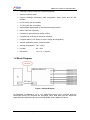
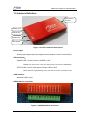
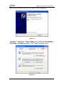
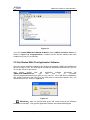
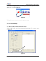
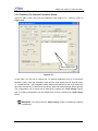
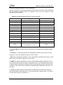
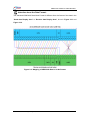
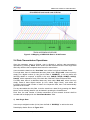
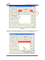
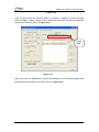
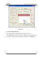
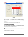
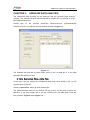
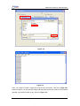
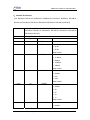
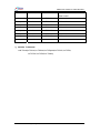
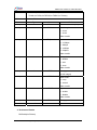
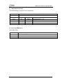
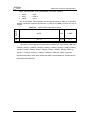
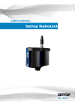
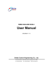
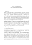
EMBC1000-USB429-42
USER MANUAL
(Simplified V1.5.1)
Orbita Control Engineering Co., Ltd.
Address:Orbita TechPark, 1 Baisha Road, Guangdong, China, 519080
Tel: +86 756 3391979
Fax: +86 756 3391980
Web: www.myorbita.net
EMBC1000-USB429-42 USER MANUAL
First published in 2008 by
Orbita Control Engineering Co. Ltd.
Zhuhai, China
© Orbita Control Engineering Co. Ltd.
All rights reserved. No part of this publication may be reproduced, stored in a retrieval system, or
transmitted, in any form, or by any means, electronic, mechanical, photocopying, recording or
otherwise, without prior permission, in writing, from Orbita Control Engineering Co.
Ltd.(thereafter called “Orbita”).
User’s Manual Information
This document contains the simplified User Manual of EMBC1000-USB429-42 device.
Orbita reserves the rights to make changes in the products or specifications contained in this
document in order to supply the best possible products. Orbita does not assume responsibility for
errors that may appear in this manual.
Orbita also assumes no responsibility for the use of this device beyond the product specifications.
Applications for any target hardware connections contained in this publication are for illustration
purposes only and Orbita makes no representation or warranty that such applications will be
suitable for the use specified without further testing or modification according to the target
hardware specifications.
The software associated with the shipped device shall not be used for other purpose except as
stated in the terms of the software license agreement, or with special permission from Orbita.
Special Notes
EMBC, EIPC, S698, OBT429, OBT1553B, ORION are registered trademarks of Orbita Control
Engineering Co. Ltd..
Microsoft, Windows XP, Windows 2000 are registered trademarks of Microsoft Corporation.
All other products mentioned in this User’s Manual are trademarks or registered trademarks of
their respective manufacturers.
Application of EMBC1000-USB429-42
EMBC1000-USB429-42 is an USB device that provides new levels of performance and flexibility
for systems interfacing to ARINC429 data bus, including data transmission, data reception,
real-time data display, data recording and replay, data post analysis, etc..
Zhuhai Orbita Control Engineering Co., Ltd.
- ii -
EMBC1000-USB429-42 USER MANUAL
CONTENT
CHAPTER 1. INTRODUCTION........................................................................................................1
1.1 ABOUT EMBC1000-USB429-42 DEVICE ....................................................................................1
1.2 APPLICATIONS ...............................................................................................................................1
1.3 CHARACTERISTICS ........................................................................................................................1
1.4 BLOCK DIAGRAM ...........................................................................................................................2
1.5 INTERFACE DEFINITION .................................................................................................................3
1.6 ELECTRIC PROPERTIES OF ARINC429 BUS CONNECTIONS ......................................................4
1.7 STEPS OF USING EMBC1000-USB429-42 DEVICE ..................................................................4
1.8 RESOURCES ON CD-ROM ...........................................................................................................5
CHAPTER 2. OPERATIONS AND SETUP ....................................................................................6
2.1 DRIVERS INSTALLATION .................................................................................................................6
2.2 GET STARTED WITH THE APPLICATION SOFTWARE .....................................................................9
2.3 PARAMETER SETUP .....................................................................................................................10
2.3.1 Receive (Rx) Channel Parameter Setup ......................................................................10
2.3.2 Transmit (Tx) Channel Parameter Setup ......................................................................12
2.4 DATA TRANSMISSION OPERATIONS .............................................................................................15
2.5 DATA RECEIVING OPERATIONS ...................................................................................................19
CHAPTER 3. ARINC429 DATA ANALYSIS .................................................................................21
CHAPTER 4 FIRMWARE UPDATE .................................................................................................26
CHAPTER 5. DEVELOP YOUR OWN APPLICATION SOFTWARE.......................................28
5.1 API LIBRARY................................................................................................................................28
5.2 EXAMPLE SOURCE CODE ...........................................................................................................29
5.3 API DESCRIPTION .......................................................................................................................29
CHAPTER 6. PRODUCT ORDERING INFO................................................................................36
Zhuhai Orbita Control Engineering Co., Ltd.
- iii -
EMBC1000-USB429-42 USER MANUAL
APPENDIX A: ARINC429 PROTOCOL INTRODUCTION ..........................................................37
Zhuhai Orbita Control Engineering Co., Ltd.
- iv -
EMBC1000-USB429-42 USER MANUAL
CHAPTER 1.
INTRODUCTION
1.1 About EMBC1000-USB429-42 device
Figure 1-1 EMBC1000-USB429-42 Device
EMBC1000-USB429-42 is an USB device. It provides a new level of performance and
flexibility for system interfacing and data acquisition to ARINC429 data bus target
hardware and systems, including data transmission, data receiving, real-time data display,
data recording and replay, data post analysis, etc..
Designed with up to four ARINC429 receive (Rx) channels and two ARINC429 tranmit
(Tx) channels, EMBC1000-USB429-42 device operates in 100k/48k/12.5kbps rates with
software adjustable.
EMBC1000-USB429-42 device is powered by an external power supply -- 5VDC power
adaptor.
The device comes with user manual, software drivers, sample application source codes,
and ARINC429 bus data analysis software. The ARINC429 bus data analysis software
provides a rich set of tools for advanced monitoring through real time display, and data
post analysis through recorded data replay.
1.2 Applications
EMBC1000-USB429-42 device is the perfect COTS solution for data acquisition and
analysis for ARINC429 data bus target hardware and systems. The USB interface makes
it suitable for use with any PC or workstation or specialized test equipment. Designed
with compact size, light weight, and durable construction, EMBC1000-USB429-42 is a
useful and ideal tool for lab test, on-site test and maintainence, and in field repairement,
test, and services of ARINC429 related flight device, instrumentation and equipment.
1.3 Characteristics
• USB 2.0 Interface with PC;
• Four Receive(Rx) Channels, Two Transmit(Tx) Channels;
Zhuhai Orbita Control Engineering Co., Ltd.
- 1 -
EMBC1000-USB429-42 USER MANUAL
• 100k/48k/12.5kbps rates with software adjustable;
• Support 32/25 bit mode;
• Support message scheduling, label recognisiton, parity check and the SDI
decode;
• Rx FIFO size upto 512*32bits;
• Tx FIFO size upto 512*32bits;
• Support Bulk append data for transmit and timing transmit ;
• Built-in Self Test Capability;
• Powered by external power supply (5VDC);
• Complete set of drivers for Windows XP/2000;
• Complete ANSI C DLL library for user’s design and integration;
• Sample application source codes provided.
• Working temperature: [-40~+85]℃;
• Humitity:
0%~80%;
• Dimension:
133 × 75 × 18 (mm);
1.4 Block Diagram
Figure 1-2 Block Diagram
As illustrated in Figure1-2, up to four ARINC429 receive (Rx) channels and two
ARINC429 tranmit (Tx) channels are supported, which shall allow upto six ARINC429
target hardware (channels) be connected with EMBC1000-USB429-42 device.
Zhuhai Orbita Control Engineering Co., Ltd.
- 2 -
EMBC1000-USB429-42 USER MANUAL
1.5 Interface Definition
ARINC429 bus
Connector
POWER Input
STATUS LED
POWER LED
USB Interface
Figure 1-3 Device Interface description
Power Input:
5VDC power adaptor input (the adaptor works between 100VAC and 240VAC).
LED Indication:
POWER LED : Power indicator, GREEN or OFF
GREEN color when power is ON, OFF when power to the device is ABNORMAL;
STATUS LED : Device RUN status indicator, RED or OFF
Status LED shall toggle (Blinking) every 1000 data received or transmited in total
USB interface:
Standard USB 2.0 port
ARINC429 bus connector:
Figure 1-4 ARINC429 Bus Connector
Zhuhai Orbita Control Engineering Co., Ltd.
- 3 -
EMBC1000-USB429-42 USER MANUAL
Table 1-1 ARINC429 Bus Connector Pin Definition
Pin
Signal
Direction
Description
To Target
hardware
1
TX2A
output
Tx channel 2 A
To Rx channel
2
TXAB
output
Tx channel2 B
To Rx channel
3
TX1A
output
Tx channel1 A
To Rx channel
4
TX1B
output
Tx channel1 B
To Rx channel
5
RX1A
input
Rx channel1 A
To TX channel
6
RX1B
input
Rx channel1 B
To TX channel
7
RX2A
input
Rx channel2 A
To TX channel
8
RX2B
input
Rx channel2 B
To TX channel
9
RX3A
input
Rx channel3 A
To TX channel
10
RX3B
input
Rx channel3 B
To TX channel
11
RX4A
input
Rx channel4 A
To TX channel
12
RX4B
input
Rx channel4 B
To TX channel
1.6 Electric Properties Of ARINC429 Bus Connections
For the ARINC429 receive (Rx) channels, when you connect with any target hardware,
the max input voltage of any signals shall be: ±30VDC.
As for the ARINC429 tranmit (Tx) channels, their bus data signals are standrard outputs:
+5V±5% for High Voltage and-5V±5% for Low Voltage. If the ARINC429 tranmit (Tx)
channel works under full load, the max resistance and capacitance impedance of the load
is: 400Ω/30,000pF; while the max resistance and capacitance impedance of the load is:
4000Ω/10,000pF when the ARINC429 tranmit (Tx) channel works only under half load.
1.7 Steps Of Using EMBC1000-USB429-42 Device
Before you use this device for your project, please make sure you will take the following
steps:
1.
inspect the received product package carefully
2.
Connect this device with your target hardware and PC
3.
Power ON
4.
Install the drivers software onto your PC (read next chapter)
5.
Install the application software onto your PC and setup the parameters (read
next chapter)
When all above gets done, then it is ready for you to use and explore this device. You
may use the provided ANSI C DLL library (and sample application source codes) to
create and construct a new application.
Zhuhai Orbita Control Engineering Co., Ltd.
- 4 -
EMBC1000-USB429-42 USER MANUAL
1.8 Resources on CD-ROM
The CD-ROM includes:
Directory: G:\
(assume G:)
\ ApplicationSoftware
EMBC1000-USB429-42.exe
executable file
\ doc
EMBC1000-USB429-42UserManual.pdf
\ driver
User manual
Board oriented drivers
EMBC1000-USB429-42.sys
EMBC1000-USB429-42.inf
\ Userdesign
For user’s development use
\APILibrary
429USBdll.lib
429USBdll.dll
\ sample
VC++ sample
\DataAnalysis
data anaysis executable file
Data Convert.exe
\FirmwareUpdate
EMBC1000-USB429-FirmwareUpdate.exe
\ Training
Video files to show the operations
Install.avi
Loopback.avi
Savefile.avi
Zhuhai Orbita Control Engineering Co., Ltd.
- 5 -
EMBC1000-USB429-42 USER MANUAL
CHAPTER 2.
OPERATIONS AND SETUP
2.1 Drivers Installation
Connect the EMBC1000-USB429-42 device to PC with the USB cable, turn on the power
adaptor (5VDC), and insert the provided CD-ROM into you PC with Windows XP/2000,
now you are ready to install the drivers onto your PC.
Now in few seconds, the PC will detect the newly connected hardware, and the “New
Hardware Wizard” will be started automatically, as shown in Figure 2-1:
Figure 2-1
Choose “Install from a list or specific location”, then click “Next”, shown in Figure2-2:
Zhuhai Orbita Control Engineering Co., Ltd.
- 6 -
EMBC1000-USB429-42 USER MANUAL
Figure 2-2
Choose”Include this location in the search” and browse driver direction, then clik
“Next”. If the drivers software is the right version for the device, PC will check and then
install it automatically, shown in Figure2-3:
Figure 2-3
Zhuhai Orbita Control Engineering Co., Ltd.
- 7 -
EMBC1000-USB429-42 USER MANUAL
When the driver installation gets done, click “finish”, shown in Figure 2-4:
Figure 2-4
It will bring us back to the Windows desktop. Now browser the “My computer” ->
“properties” -> “hardware” -> “Device Manager”, you will find our device drivers –
“Orbita EMBC1000-USB429-42 Board” - under “ USB I/O controller device”:
Figure 2-5
Zhuhai Orbita Control Engineering Co., Ltd.
- 8 -
EMBC1000-USB429-42 USER MANUAL
Figure 2-6
If you find “Orbita EMBC1000-USB429-42 Board” under “USB I/O controller device” as
shown in Figure 2-6, Congratulations! It means that the drivers software has been
installed onto your PC successfully.
2.2 Get Started With The Application Software
Once the drivers software installation gets finished successfully, EMBC1000-USB429-42
device is ready for use. The next step is to install the Application Software onto your PC
so to make full use of this device.
Now
please
double
click
the
application
software
executable
file
“EMBC1000-USB429-42.exe”
(you
can
find
it
on
CD-ROM,
Directory/ApplicationSoftware/) to get it to run in your PC. If the USB device initialization
fails (mostly because of the FAULTY of the USB cable or connection between PC), you
will see the error info, Shown in Figure 2-7.
Figure 2-7
)
Attention:Wait 3~5 seconds after power ON, make sure that the USB gets
initialized successfully,then get the application software executable started again.
Zhuhai Orbita Control Engineering Co., Ltd.
- 9 -
EMBC1000-USB429-42 USER MANUAL
If the USB device gets initialized successfully, you will see the application software
Startup Logo as shown in Figure 2-8.
Figure 2-8
To this point, you are allowed to carry on the parameter setup.
2.3 Parameter Setup
2.3.1 Receive (Rx) Channel Parameter Setup
Click the “RX-1” button, you will enter the parameter setup page of Rx-1 channel, shown
in Figure 2-9:
Receive Data Display Area
Figure 2-9
Zhuhai Orbita Control Engineering Co., Ltd.
- 10 -
EMBC1000-USB429-42 USER MANUAL
Now you are free to setup the Rx channel parameters, such as: Word length, baudrate,
parity, SDI decode, label check, etc.. After changing the parameter, you must press the
“Apply setting” button to make it valid, and the configuration can be saved into a data
file by pressing the “Save Setting” button, and an existing configuration can be loaded
from a file by pressing the “load setting” button.
Attention: User must press the “Apply setting” button to enable the changes
)
of parameters.
Possible assignment value for each parameter
Under the receive (Rx) channel parameter setup window, the content of each parameter
can be selected by pulling down the respective menu bar. The contents of each
parameter are listed below.
Table 2-1 Possible Assignment Value For Each Parameter
Menu Item
Range
Default
Word Length
32, 25 bit
32
Baud Rate
12.5, 48, 100 ,50Kbps
12.5
Parity Check
Disable, odd, even
Disable
SDI Decode
Disable, 00,01,10,11 (binary)
Disable
Label Check
Disable, enable
Disable
L1
0x00~0xFF
00
L2
0x00~0xFF
00
L3
0x00~0xFF
00
L4
0x00~0xFF
00
L5
0x00~0xFF
00
L6
0x00~0xFF
00
L7
0x00~0xFF
00
Zhuhai Orbita Control Engineering Co., Ltd.
- 11 -
EMBC1000-USB429-42 USER MANUAL
2.3.2 Transmit (Tx) Channel Parameter Setup
Click the “TX-1” button will enter the parameter setup page of Tx-1 channel, shown in
Figure 2-10:
Data Display Area
Figure 2-10
In this Page, you are free to change the Tx channel parameter such as: word length,
baudrate, parity, word gap, repetition mode and the work mode such as:”Normal mode”
or “Loopback mode”. In the loopback mode, EMBC1000-USB429-42 can only receive the
data from the internal Tx channels of the device, data from external target will be ignored.
The configuration can be saved into a data file by pressing the “Save Setting” button,
and an existing configuration can be loaded from a file by pressing the “load setting”
button.
) Attention: You must press the “Apply setting” button to enable the changes
of Tx parameters.
Zhuhai Orbita Control Engineering Co., Ltd.
- 12 -
EMBC1000-USB429-42 USER MANUAL
Possible Assignment Value For Each Parameter
Under the transmit (Tx) channel parameter setup window, the content of each parameter
can be selected by pulling down the respective menu bar. The contents of each
parameter are listed below.
Table 2-2 Possible Assignment Value For Each Parameter
Menu Item
Range
Default
Word Length
32, 25 bit
32
Baud Rate
12.5, 48, 100,50 kbps
12.5
Parity Check
Disable, odd, even
Disable
Word Gap
5 - 255
5
Work Mode
Normal, Loopback
Normal
Repetition Mode *
Disable, Enable
Disable
Time Gap **
0-5000
2000 ms
WORD
0x0~0xFFFFFFFF
blank
PAR
0,1, (binary)
blank
SDI***
00,01,10,11 (binary)
blank
SSM****
00,01,10,11 (binary)
blank
LAB*****
HEX data (0x0~0xFF)
blank
Data
32-Bit Mode: 0x0~0x7FFFF
25-Bit Mode: 0x0~FFFF
blank
* Repetition Mode: The max number of data can be transmitted under Repetition Mode
are 256.
** Time Gap: the time gap between two Repetitions transmits. Time Gap can only be
assigned a value when Repetition Mode is under “Enable”.
***SDI: Source Destination Identifiers. In the 32-bit ARINC 429 Data Word Format, it uses
Bits 9 and 10. SDI field is valid only in 32 bit mode.
****SSM: This section describes the coding of the Sign/Status Matrix (SSM) field. In the
32-bit ARINC 429 Data Word Format, it uses Bits 30 and 31.The SSM field may be used
to report hardware equipment condition (fault/normal), operational mode (functional test),
or validity of data word content (verified/no computed data). SSM field is valid only in 32
bit mode.
*****LAB: The label words are quite important in ARINC429 and identify the data type
and the parameters associated with it, such as latitude data, longitude data. In all case of
the Data Word Format, it uses Bits 1~8.
Zhuhai Orbita Control Engineering Co., Ltd.
- 13 -
EMBC1000-USB429-42 USER MANUAL
)
Attention about the Data Format:
The standard ARINC429 Data Word Format is different from the format of the data in the
“Send data Display Area” or “Receive data Display Area”, show in Figure 2-11 and
Figure 2-12.
Figure 2-11 Mapping of ARINC429 Data in 32-bit Format
Zhuhai Orbita Control Engineering Co., Ltd.
- 14 -
EMBC1000-USB429-42 USER MANUAL
Figure 2-12 Mapping of ARINC429 Data in 25-bit Format
2.4 Data Transmission Operations
After the parameter setup is finished, user is allowed to perform data transmission
operations by pressing “Send” button under the data transmit window. Both single data
and bulky data are the acceptable data format for transmission.
User can add the data into the “Send data” area, either in single or bulk data format.
For single data, there is a dedicated data entry area under “Single add”, where one may
simply put a digital number (in Hex) into the field of “WORD(H)”, or he may define the
following details to compose a WORD to be sent: PAR(B), SDI(B), SSM(B), LAB(H),
Data(H), which represents Parity, SDI check bits, SSM bits, Label check and Data.
For Bulky data, there is a dedicated data entry area under “Bulk add”, where one may
simply create a base digital number (in Hex, called ”Begin Data”), and define the
increment and the total number of data in the respective field, then it will automatically
generate a set of data.
For any data added into this field, it can be saved into a data file by pressing the “Save”
button, and an existing data file can be loaded in pressing the “Load” button.
Each time, the total number of Words transmitted via this transmit channel shall be
counted and be displayed in the “Send Data Number” field.
1) Add Single Data
User can put a digital number (in Hex) into the field of “WORD(H)” to add to the send
Data display district Shown in Figure 2-13:
Zhuhai Orbita Control Engineering Co., Ltd.
- 15 -
EMBC1000-USB429-42 USER MANUAL
Press
“add”
Transmit Data
Figure 2-13
When the user presses the “Add” button, the data will be displayed in the Send Data
Display Area, and the data will be decoded into Five Part, Shown in Figure 2-14:
Send Data Display Area
Zhuhai Orbita Control Engineering Co., Ltd.
- 16 -
EMBC1000-USB429-42 USER MANUAL
Figure 2-14
User can also define the following details to compose a WORD to be sent: PAR(B),
SDI(B), SSM(B), LAB(H), Data(H), which represents Parity, SDI decode bits, SSM bits,
Label check and Data, Shown in Figure 2-15:
Press
“add”
Figure 2-15
When user press the “Add” button, data will be displayed in the Send Data Display Area,
and data will be decoded into Five Part, Shown in Figure 2-16:
Zhuhai Orbita Control Engineering Co., Ltd.
- 17 -
EMBC1000-USB429-42 USER MANUAL
Data Display Area
Figure 2-16
2) Add the Bulky Data (Bulk add)
For Bulk add data, user may simply create a base digital number (in Hex,
called ”Begin Data”), and define the increment and the total number of data in the
respective field, then it will automatically generate a set of data Shown in Figure 2-17:
Zhuhai Orbita Control Engineering Co., Ltd.
- 18 -
EMBC1000-USB429-42 USER MANUAL
Send Data Display Area
Figure 2-17
3) Data transmission and termination
Once the data is ready, the user is allowed to perform data transmission operations by
pressing “Send” button under the data transmit window. The Status LED will keep
blinking to reflect the data transmission in progress. The total number of WORDs
transmitted via this transmit channel will be counted and be displayed in the “Send Data
Number” field.
Data transmission can be terminated any time by pressing “Stop” button.
2.5 Data Receiving Operations
Data Receiving Operation is quite simple. Once the Rx channel parameter setup is
completed, then the user can simply press “Start” button to enable the Rx channel to
start to receive data from the connected target hardware.
)
Attention: It is very important that the communication parameter setup between
target hardware and this device should be identical.
The data receiving is shown in Figure 2-18.
Zhuhai Orbita Control Engineering Co., Ltd.
- 19 -
EMBC1000-USB429-42 USER MANUAL
Receive Data Display Area
Figure 2-18
For any data received, it can be saved into a data file by pressing the “Save” button, or
the user may discard it by pressing “Clear” button.
Zhuhai Orbita Control Engineering Co., Ltd.
- 20 -
EMBC1000-USB429-42 USER MANUAL
CHAPTER 3.
ARINC429 DATA ANALYSIS
The ARINC429 data received can be analyzed with the provided Data Analysis
software. The software will deal with the data either saved in the .txt data file or in the
data field entered on-line.
Double
click
on
the
software
ARINC429
DataConvert.exe
(G:\DataAnalysis\
DataConvert.exe), you will see the main window showed in Figure 3-1.
Figure 3-1
The software will deal with the data either saved in the .txt data file or in the data
operation field entered on-line:
1) Data Conversion from a Data File
In this way, user can analyze the ARINC429 data which have saved in the *.txt file
(assume Source File.txt).
Click the “Source File” button to open the data file.
The ARINC429 data saved in the Source File are in Hex, the first line is always the
definition of the word length (25 or 32 bit), following are the data (each word per
line) ,shown in Figure 3-2 and Figure 3-3:
Zhuhai Orbita Control Engineering Co., Ltd.
- 21 -
EMBC1000-USB429-42 USER MANUAL
Figure 3-2
Figure 3-3
Then, you need to create a target file to save such conversion. Click the “Target File”
button to build a *.txt file (assume Target File.txt) which saved the results of the analysis
(actually, conversion results so far), shown in Figure 3-4:
Zhuhai Orbita Control Engineering Co., Ltd.
- 22 -
EMBC1000-USB429-42 USER MANUAL
Figure 3-4
Click the “Convert” button, when the analysis (conversion) is completed, the “Convert
number” area will show the total number of the words analyzed. And then you can open
the Target File(Target File.txt) to study the results, shown in Figure 3-5 and Figure 3-6:
Zhuhai Orbita Control Engineering Co., Ltd.
- 23 -
EMBC1000-USB429-42 USER MANUAL
Figure 3-5
Figure 3-6
2) Data Conversion: in Data Operation field
There is a dedicated data entry area under “Data Operation”. One may simply create
a set of data by using the base digital number (in Hex, here we termed it to be ”Begin
Data”), defining the increment (accept 0 to 0xFFFFF) and the total number (accept 0 to
65535) of data in the respective field.
Zhuhai Orbita Control Engineering Co., Ltd.
- 24 -
EMBC1000-USB429-42 USER MANUAL
Once the data is configured, you may click on the “Convert” button, it will automatically
generate a set of data and perform conversion over them automatically. The attributes
such as PAR, SDI, SSM, LAB, DATA, etc. will be generated and displayed in the ”Data
Display Area”, shown in Figure 3-7:
Data Display Area
Figure 3-7
Zhuhai Orbita Control Engineering Co., Ltd.
- 25 -
EMBC1000-USB429-42 USER MANUAL
CHAPTER 4 FIRMWARE UPDATE
)
Attention:
user
must
close
the
application
software
executable
file
“EMBC1000-USB429-42.exe” before use the Firmware Update software.
EMBC1000-USB429-42
can
be
update
by
the
software
call
“EMBC1000-USB429-FirmwareUpdate.exe”, before use the software user must close
the application software EMBC1000-USB429-42.exe, then click the firmware update
software “EMBC1000-USB429-FirmwareUpdate.exe”, as shown in Figure 2-20:
Figure 4-1
Click the “Browse” button to select the download file *.bin, then click “Begin” button to
download, as shown in Figure4-2 Figure4-3:
Figure4-2
Zhuhai Orbita Control Engineering Co., Ltd.
- 26 -
EMBC1000-USB429-42 USER MANUAL
Figure4-3
When update finish, click “ Exit “ button ,shown as Figure4-4 :
Figure4-4
Attention: Don’t shutdown the power or pull out the USB cable when
firmwareupgrade in process, otherwise will cause upgrade process fail and device not
work well.
Zhuhai Orbita Control Engineering Co., Ltd.
- 27 -
EMBC1000-USB429-42 USER MANUAL
CHAPTER 5.
DEVELOP YOUR OWN APPLICATION
SOFTWARE
To allow the user to develop his own application software or project,
EMBC1000-USB429-42 device comes with drivers software, API (Application
Programming Interface) library and user oriented application software, running under
Windows 2000 or Windows XP. The user oriented application software has been
designed with the capabilities of simulating the outputs of various airborne systems,
receiving inputs from these systems, and providing bus data analysis functions. API
library is also provided together with example source code (Visual C++), which allows
users to easily develop their own application software or project based on the real world
applications.
5.1 API Library
When user begins to write application software for the device, you should finish the
settings below in you project (build in Visual C++ 6.0):
1、 Copy
the
API
library:
429USBdll.lib
and
UserDesign\APILibrary) to the project’s root directory.
429USBdll.dll
(G:\
2、 Add the 429USBdll.lib to the project: ProjectÆSettingÆLink, Shown in the
Figure 5-1:
Figure 5-1 Add 429USBdll.lib to project
3、 Add these function in your program’s head file Shown in Figure 5-2:
Zhuhai Orbita Control Engineering Co., Ltd.
- 28 -
EMBC1000-USB429-42 USER MANUAL
extern "C" _declspec(dllexport) BOOL FillDeviceList();
extern "C" _declspec(dllexport) void RXInit(int RXnum,int RXWord,int RXSpeed,int
RXJiOu,int RXSDI,int RXLAB,int RXLab1,int RXLab2,int RXLab3,int RXLab4,int
RXLab5,int RXLab6,int RXLab7);// initialize RX
extern "C" _declspec(dllexport) void TXInit(int TXnum,int TXWord,int TXSpeed,int
TXJiOu,int TXDis,int TXZHC,int TXDIS,int TXtime);// initialize TX
extern "C" _declspec(dllexport) void RXEnable(int RXnum);
extern "C" _declspec(dllexport) void RXDisable(int RXnum);
extern "C" _declspec(dllexport) int ReadData(int &Rxnum,DWORD* Readbuffer,int
&lenth);
extern "C" _declspec(dllexport) BOOL WriteData(int TXnum,DWORD* Writebuffer,int
speed,int lenth);
extern "C" _declspec(dllexport) void USBclosed();
extern "C" _declspec(dllexport) void Senddata_Circle(int TXnum,DWORD* Writebuffer,int
speed,int lenth);
extern "C" _declspec(dllexport) void StopSenddata_Circle(int TXnum,long &lenth);
Figure 5-2
4、 Now the API setup is done. When you build your project, VC++ will link the APIs
automatically and add them to your project.
5.2 Example Source Code
The example source code will show the user how to use the API. User can get the detail
from the CD-ROM(G:\ UserDesign\sample).
5.3 API Description
1.Initialize Device:
BOOL FillDeviceList();
Model
BOOL FillDeviceList()
Function
Initialize device
Parameter
Type
Define
Return Value
BOOL
TRUE: Initialize success.
FALSE: Initialize failed.
Zhuhai Orbita Control Engineering Co., Ltd.
- 29 -
EMBC1000-USB429-42 USER MANUAL
2.Initialize Rx Channel:
void RXInit(int RXnum,int RXWord,int RXSpeed,int RXJiOu,int RXSDI,int RXLAB,int
RXLab1,int RXLab2,int RXLab3,int RXLab4,int RXLab5,int RXLab6,int RXLab7)
Model
void RXInit(int RXnum,int RXWord,int RXSpeed,int RXJiOu,int RXSDI,int
RXLAB,int RXLab1,int RXLab2,int RXLab3,int RXLab4,int RXLab5,int
RXLab6,int RXLab7)
Function
Initialize RX channel
Parameter
Type
Name
Define
input
int
RXnum
RX channel number(1-4)
input
int
RXWord
Word length:
0 - 32 bit
1 - 25 bit
Other invalid
input
int
RXSpeed
baudrate:
0 - 12.5kbps
1 - 48kbps
2 - 100kbps
3 – 50kpbs
Other invalid
input
int
RXJiOu
Parity check:
0 - disable
1 - odd
2 - even
Other invalid
input
int
RXSDI
SDI decode:
0 - disable
1 - 00
2 - 01
3 - 10
4 - 11
Other invalid
input
int
RXLAB
Label check:
0 - disable
Zhuhai Orbita Control Engineering Co., Ltd.
- 30 -
EMBC1000-USB429-42 USER MANUAL
1 - enable
Other invalid
input
int
RXLab1
Lab1 number
input
int
RXLab2
Lab2 number
input
int
RXLab3
Lab3 number
input
int
RXLab4
Lab4 number
input
int
RXLab5
Lab5 number
input
int
RXLab6
Lab6 number
input
int
RXLab7
Lab7 number
Return Value
void
3.Initialize Tx Channel:
void TXInit(int TXnum,int TXWord,int TXSpeed,int TXJiOu,int TXDis,
int TXZHC,int TXDIS,int TXtime);
Zhuhai Orbita Control Engineering Co., Ltd.
- 31 -
EMBC1000-USB429-42 USER MANUAL
Model
void TXInit(int TXnum,int TXWord,int TXSpeed,int
TXJiOu,int TXDis,int TXZHC,int TXDIS ,int TXtime);
Function
Initialize TX channel
Parameter
Type
Name
input
int
TXnum
TX channel number(1-2)
input
int
TXWord
Word length:
Define
0 - 32 bit
1 - 25 bit
Other invalid
input
int
TXSpeed
baudrate:
0 - 12.5kbps
1 - 48kbps
2 - 100kbps
3 – 50kpbs
Other invalid
input
int
TXJiOu
Parity check:
0 - disable
1 - odd
2 - even
Other invalid
input
int
TXDis
Word gap:
(4-255 integer)
input
int
TXZHC
Work mode :
0 – loop
1 - normal
Other invalid
input
int
TXDIS
repetition:
0 - enable
1 - disable
Other invalid
input
int
Return Value
void
TXtime
Time gap
4. Rx Channel Enable
RXEnable(int RXnum)
Zhuhai Orbita Control Engineering Co., Ltd.
- 32 -
EMBC1000-USB429-42 USER MANUAL
Model
void
RXEnable(int RXnum)
Function
Enable the Rx Channel
Parameter
Type
Name
Define
input
int
RXnum
Rx Channel Num: 1~4
Return Value
Void
5. Rx Channel Disable
void RXDisable(int RXnum)
Model
void RXDisable(int RXnum)
Function
Disable the Rx Channel
Parameter
Type
Name
Define
input
int
RXnum
Rx Channel Num: 1~4
Return Value
void
6. ReadData
int ReadData(int &Rxnum,DWORD* Readbuffer,int &lenth)
Model
Function
int ReadData(int &Rxnum,DWORD* Readbuffer,int &lenth)
ReadBack the data from Rx Channel
Parameter
Type
Name
output
int
RXnum
input
DWORD
Readbuffer
Define
Rx Channel Num: 1~4
Array used to store the data from the Rx
Channel, Maxium 511 ARINC429 words
output
int
Return Value
int
lenth
Data Length from Rx Channel
Return value 0:
No Data Return
Return value 1:
Read Data Succeed
7. Transmit Data
BOOL WriteData(int TXnum,DWORD* Writebuffer,int speed,int lenth)
Zhuhai Orbita Control Engineering Co., Ltd.
- 33 -
EMBC1000-USB429-42 USER MANUAL
Model
Function
BOOL WriteData(int TXnum,DWORD* Writebuffer,int speed,int lenth)
Transmit Data From Tx Channel
Parameter
Type
Name
input
int
TXnum
input
DWORD *
Writebuffer
Define
Tx Channel Num : 1~2
Array used to store the data from the Tx
Channel, Maxium 511 ARINC429 words
input
int
speed
Transmit BaudRate:
1 : 100kbps/48kbps/50kbps;
0 : 12.5kbps;
input
int
lenth
Transmit Data Length:
When speed =1: The Maxium transmit data
Length is 511 ARINC429 words;
When speed =0: The Maxium transmit data
Length is 255 ARINC429 words;
Return Value
BOOL
Return Value :
FALSE : Transmit Fail;
TRUE : Transmit Succeed;
8.Repeat Transmit Data
void Senddata_Circle(int TXnum,DWORD* Writebuffer,int speed,int lenth)
Attention: This Function is valid when the Repetition Mode enable;
Model
Void Senddata_Circle(int TXnum,DWORD* Writebuffer,int speed,int
lenth)
Function
Parameter
Repeat Transmit The Data Of The Tx Channel
Type
Name
input
int
TXnum
input
DWORD *
Writebuffer
Define
Tx Channel Num : 1~2
Array used to store the data from the Tx
Channel, Maxium 256 ARINC429 words
input
int
speed
Transmit BaudRate:
1 : 100k/48kbps/50kbps;
0 : 12.5kbps;
input
int
Return Value
Void
Zhuhai Orbita Control Engineering Co., Ltd.
lenth
Transmit Data Length
- 34 -
EMBC1000-USB429-42 USER MANUAL
9. Stop Repeat Transmit
void StopSenddata_Circle(int TXnum,long &lenth)
Model
void StopSenddata_Circle(int TXnum,long &lenth)
Function
Stop Repeat Transmit The Data Of The Tx Channel
Parameter
Type
Name
input
int
TXnum
output
long
lenth
Return Value
void
Define
Tx Channel Num : 1~2
The Total Number of the data have been Send
10. Close the USB Device
void USBclosed();
Model
Function
Return Value
void USBclosed()
Close the USB Device
void
Zhuhai Orbita Control Engineering Co., Ltd.
- 35 -
EMBC1000-USB429-42 USER MANUAL
CHAPTER 6.
Product Number
PRODUCT ORDERING INFO
Baud rate
Rx
Tx
Channel Channel
Software support
100K
12.5K
48K
Windows 2000 or Windows XP
EMBC1000USB429-42
4
2
√
√
√
based drivers and application
software
Correlative Product
EMBC1000-PC
I429-42
EMBC1000-PC
I429EI-42
Rx
Tx
Mode
Inject
Channel
Channel
50K
USB429EI-42
Error
48K
EMBC1000-
Interface
12.5K
Product Number
100K
Baudrate
USB
√
2
√
√
√
√
4
Software support
Windows 2000 or Windows
XP based drivers and
application software
Windows 2000 or Windows
PCI
4
2
√
√
√
√
XP
based
drivers
and
application software
Windows 2000 or Windows
PCI
√
Zhuhai Orbita Control Engineering Co., Ltd.
4
2
√
√
√
√
XP
based
drivers
application software
- 36 -
and
EMBC1000-USB429-42 USER MANUAL
APPENDIX A: ARINC429 PROTOCOL INTRODUCTION
ARINC429 is an international standard for Digital Information Transfer System
(DITS). It is application-specific for commercial and transport aircraft. It ignores the
complexities of different manufacturers’ avionics system interfaces and supplies
uniform flatform for system communication.
Based on the requirements of ARINC Specification 429, digital information is
transmitted by wires in unidirectional data bus, differential coupling or twisted pairs.
So ARINC429 is serial communication actually. The ARINC429 standard supports
High, Low, and Null states.
ARINC data words are always 32 or 25 bits in length. Transmission of
sequential words is separated by at least four Null bits. Each ARINC word contains
a parity bit, 8-bit label. The label words are quite important in ARINC429 and identify
the data type and the parameters associated with it, such as latitude data, longitude
data. The rest data bits of the word are divided into different fields based on the
label. For making communication fully standardized and avoiding conflicts, all of the
flight functions have been equipped with given labels and data formats.
When a 32-bit ARINC word is transmitted, each word contains:
• Parity
:
bit32
• SSM
:
bit31~30,
Sign Status Matrix
• Data
:
bit29~11
• SDI
:
bit10~9,
Source Destination Identifiers
• Label
:
bit8~1
The 32-bit ARINC Word typically use the format shown in Table A-1 which
includes five primary fields, namely P (parity), SSM, Data, SDI, and Label. Attention,
ARINC convention numbers the bits from 1 (LSB) to 32 (MSB), not from 0 to 31 as
usually.
The order of 32-bit data word transmitted on ARINC bus is as follows (LSB first):
Label(8)- Label(7)- Label(6)- Label(5)- Label(4)- Label(3)- Label(2)- Label(1)SDI(1)- SDI(2)- Data(1)- Data(2)- Data(3)- Data(4)- Data(5)- Data(6)- Data(7)Data(8)- Data(9)- Data(10)- Data(11)- Data(12)- Data(13)- Data(14)- Data(15)Data(16)- Data(17)- Data(18)- Data(19)- SSM(1)- SSM(2)- Parity. The least
significant bit of each byte, except the label, is transmitted first, and the label is
transmitted ahead of the data in each case.
32-bit ARINC Data Word Format
PARITY
Table A-1.
SSM
DATA
SDI
LABEL
32
31~30
29 ~ 11
10~9
8~ 1
Zhuhai Orbita Control Engineering Co., Ltd.
- 37 -
EMBC1000-USB429-42 USER MANUAL
When a 25-bit ARINC word is transmitted, each word contains:
•
•
•
Parity
Data
Label
:
:
:
bit25
bit24~9
bit8~1
The 25-bit ARINC Word typically use the format shown in Table A-2. Attention,
ARINC convention numbers the bits from 1 (LSB) to 25 (MSB), not from 0 to 25 as
usually.
25-bit ARINC Data Word Format
PARITY
Table A-2.
DATA
SDI
LABEL
25
24 ~ 9
10~9
8~ 1
The order of 25-bit data word transmitted on ARINC bus is as follows (LSB first):
Label(8)- Label(7)- Label(6)- Label(5)- Label(4)- Label(3)- Label(2)- Label(1)-Data(1)
-Data(2) -Data(3) -Data(4) -Data(5) -Data(6) -Data(7) -Data(8) -Data(9) -Data(10)
-Data(11) -Data(12) -Data(13) -Data(14) -Data(15) -Data(16) –Parity. The least
significant bit(LSB) of each word except the label is transmitted first, and the label is
transmitted with MSB first.
Zhuhai Orbita Control Engineering Co., Ltd.
- 38 -