1
EMBC1000-PCI429EI-42
USER MANUAL
(Simplified V1.5.2)
Orbita Control Engineering Co., Ltd.
Addr:Orbita TechPark, 1 BaishaRoad, Zhuhai, Guangdong, China, 519080
Tel: +86 756 3391979
Fax: +86 756 3391980
Web: www.myorbita.net
EMBC1000-PCI429E USER MANUAL
First published in 2008 by
Orbita Control Engineering Co. Ltd.
Zhuhai, China
© Orbita Control Engineering Co. Ltd.
All rights reserved. No part of this publication may be reproduced, stored in a retrieval
system, or transmitted, in any form, or by any means, electronic, mechanical, photocopying,
recording or otherwise, without prior permission, in writing, from Orbita Control Engineering
Co. Ltd.(thereafter called “Orbita”).
User’s Manual Information
This document contains the simplified User Manual of EMBC1000-PCI429EI-42 card.
Orbita reserves the rights to make changes in the products or specifications contained in this
document in order to supply the best possible products. Orbita does not assume
responsibility for errors that may appear in this manual.
Orbita also assumes no responsibility for the use of this device beyond the product
specifications. Applications for any target hardware connections contained in this publication
are for illustration purposes only and Orbita makes no representation or warranty that such
applications will be suitable for the use specified without further testing or modification
according to the target hardware specifications.
The software associated with the shipped device shall not be used for other purpose except
as stated in the terms of the software license agreement, or with special permission from
Orbita.
Special Notes
EMBC, EIPC, S698, OBT429, OBT1553B, ORION are registered trademarks of Orbita
Control Engineering Co. Ltd.
Microsoft, Windows XP, Windows 2000 are registered trademarks of Microsoft Corporation.
All other products mentioned in this User’s Manual are trademarks or registered trademarks
of their respective manufacturers.
Application of EMBC1000-PCI429EI-42
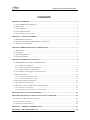
EMBC1000-PCI429EI-42 is a PCI based card that provides new levels of performance and
flexibility for systems interfacing to ARINC429 data bus, including data transmission, data
reception, real-time data display, data recording and replay, data post analysis, etc..
Orbita Control Engineering Co., Ltd.
- i-
EMBC1000-PCI429E USER MANUAL
CONTENTS
CHAPTER 1 OVERVIEW ............................................................................................................................ 1
1.1 ABOUT EMBC1000-PCI429EI-42 .......................................................................................................... 1
1.2 APPLICATIONS ......................................................................................................................................... 2
1.3 CHARACTERISTICS ................................................................................................................................... 2
1.4 SYSTEM REQUIREMENTS ......................................................................................................................... 3
1.5 SPECIAL HANDLING AND CARE ............................................................................................................... 3
CHAPTER 2 GETTING STARTED........................................................................................................... 4
2.1 ARINC429 BUS INTERFACE ..................................................................................................................... 4
2.2 ELECTRIC PROPERTIES OF ARINC429 BUS CONNECTIONS ....................................................................... 5
2.3 RESOURCES ON CD-ROM ....................................................................................................................... 5
CHAPTER 3 ERROR INJECTION AND DETECTION ........................................................................... 7
3.1 PARITY ERROR ......................................................................................................................................... 7
3.2 GAP ERROR ............................................................................................................................................. 7
3.3 SHORT WORD ERROR .............................................................................................................................. 7
3.4 LONG WORD ERROR ................................................................................................................................ 8
CHAPTER 4 OPERATIONS AND SETUP.................................................................................................. 9
4.1 HARDWARE AND ITS DRIVERS INSTALLATION ................................................................................. 9
4.1.1 Hardware installation ................................................................................................................... 9
4.1.2 Board oriented drivers Installation ............................................................................................... 9
4.1.3 LIB oriented drivers Installation................................................................................................. 13
4.2 GET STARTED WITH THE APPLICATION SOFTWARE ............................................................................... 18
4.3 PARAMETERS SETUP .............................................................................................................................. 20
4.3.1 Rx Channel Parameter Setup ...................................................................................................... 20
4.3.2 Tx Channel Parameter Setup ...................................................................................................... 22
4.4 DATA TRANSMISSION OPERATIONS ........................................................................................................ 24
4.5 DATA RECEIVING OPERATIONS .............................................................................................................. 29
4.6 ERROR INJECTION AND ERROR DETECTION OPERATION.......................................................................... 31
4.6.1 Transmit error injection................................................................................................................. 31
4.6.2 Automatic error detection in receive channels .............................................................................. 32
CHAPTER 5 DATA ANALYSIS SOFTWARE .......................................................................................... 35
CHAPTER 6 DEVELOP YOUR OWN APPLICATION SOFTWARE................................................... 40
6.1 APPLICATION PROGRAMMING INTERFACE.............................................................................................. 40
6.2 EXAMPLE SOURCE CODE ....................................................................................................................... 44
6.3 API FUNCTION DESCRIPTION................................................................................................................. 44
CHAPTER 7 PRODUCT ORDERING INFO ......................................................................................... 57
CHAPTER 8 RELATED PRODUCTS..................................................................................................... 58
Orbita Control Engineering Co., Ltd.
- ii-
EMBC1000-PCI429E USER MANUAL
APPENDIX A: ARINC429 PROTOCOL INTRODUCTION................................................................... 59
Orbita Control Engineering Co., Ltd.
- iii-
EMBC1000-PCI429E USER MANUAL
CHAPTER 1 OVERVIEW
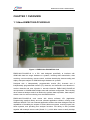
1.1 About EMBC1000-PCI429EI-42
Figure 1-1 EMBC1000-PCI429EI-42 Card
EMBC1000-PCI429EI-42 is a PCI card designed specifically to interface with
ARINC429 data bus target hardware or systems, including data transmission, data
receiving, event monitoring, remote control, real-time data display, data recording and
replay, data post analysis of ARINC429 target hardware or systems.
Designed with 4 independently programmable receive (Rx) channels and 2
independently programmable transmit (Tx) channels, and automatic error detection in
receive channels and error injection in transmit channels. EMBC1000-PCI429EI-42
card operates in 100k/50k/48k/12.5kbps rates with software configurable. This including
other advanced designs make it an ideal tool to perform data acquisition, data analysis,
remote control or event monitoring over the ARINC429 bus.
EMBC1000-PCI429EI-42 card comes with drivers software, API (Application
Programming Interface) library and user oriented application software, running under
Windows 2000/XP. The user oriented application software has been designed with the
capabilities of simulating the outputs of various airborne systems, receiving inputs from
these systems, and providing bus analyzer functions. API library is also provided
together with example source code (Visual C++), which allow users to easily develop
Orbita Control Engineering Co., Ltd.
- 1-
EMBC1000-PCI429E USER MANUAL
their own application software or project.
EMBC1000-PCI429EI-42 card is of PCI Plug-and-Play (PnP) compatible for easy
installation (any PCI 2.1, or higher, compatible slot), and multiple such cards can work
together inside one PC or workstation.
1.2 Applications
EMBC1000-PCI429EI-42 card is well suited for all types of ground support work
(development, manufacturing test, on-site maintenance, etc.), as well as on-board data
acquisition. LRU developers find that this card provides easy access for simulating
and/or testing new systems prior to use with actual flight systems. Avionics
maintenance and validation teams enjoy on-site testing and analysis with this card.
holcoter
civil aviion
Figure 1-2 Wide Applications
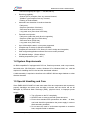
1.3 Characteristics
EMBC1000-PCI429EI-42 card features with the following characteristics:
•
•
•
•
•
•
•
•
Comply with 32-bit 33Mhz PCI bus speed;
PCI Plug-and-Play (PnP) compatible for easy installation;
Up to 4 programmable ARINC429 Rx channels;
Up to 2 programmable ARINC429 Tx channels;
Support 32/25 bit Word length;
1024 bytes FIFO for each Rx channel;
1024 bytes FIFO for each Tx channel;
Programmable baud rate (12.5Kbps、48Kbps、50Kbps、100Kbps);
•
Transmitting capability:
Queued (FIFO) transmission to any external channel;
Scheduled label and SDI transmission to any channel;
Orbita Control Engineering Co., Ltd.
- 2-
EMBC1000-PCI429E USER MANUAL
Recurrent support(Time gap: 1 ~ 99,999,999 us);
•
Receiving capability:
Queued (FIFO) reception from any external channel;
“Mailbox” type reception from any channel;
Filtering of receive labels
•
Automatic error detection in receive channels:
Parity error;
Gap error (less than 4 bit times);
Short word error (time out error);
Long word error (more than 32/25 bits);
•
Transmit error injection:
Parity error (make the parity bit to be opposite);
Gap error (make gap to be 2 bit times);
Short word error (30/23 bits);
Long word error (34/27 bits);
•
•
•
•
•
•
Up to 256 multiple cards in one system supported;
Complete set of drivers for Windows XP/2000;
Complete API and ANSI C DLL library for user’s design and integration;
Well configured application software and source codes provided;
PCI Modular design: 130mm x85mm;
Working temperature [-40℃,+85℃];
1.4 System Requirements
An IBM compatible PC equipped with PCI bus, Pentium processor, math co-processor,
hard disk drive, CD-ROM drive, monitor, Windows XP or Windows 2000, etc.. shall be
required for installing the PCI card and the associated software.
A cable assembly is required to interface to the ARINC 429 bus target hardwar or other
discrete channels.
1.5 Special Handling and Care
Since EMBC1000-PCI429EI-42 card uses state-of-the-art components and connectors,
properly handlings and cares must be taken to ensure that the device will not be
damaged by Electrical Static Discharge (ESD), physical shock, or improper power
surges.
¾ Turn off power to the PC completely;
¾ NEVER insert or remove card with power turned on;
¾ Ensure that standard ESD precautions are taken. At least,
one hand should be grounded to the power supply in order to
eliminate static potentials;
¾ Do not store the card in environment exposed to excessive
heat, magnetic fields or radiation.
Orbita Control Engineering Co., Ltd.
- 3-
EMBC1000-PCI429E USER MANUAL
CHAPTER 2
GETTING STARTED
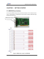
2.1 ARINC429 bus Interface
One front-panel DB25 male connector (it has been referred to “P801” inside the card) is
used for implementation of ARINC429 bus signal interface between ARINC429 target
hardware and the PCI bus.
DB25 male connector
Figure 2-1 DB25 male connetor for ARINC429
Orbita Control Engineering Co., Ltd.
- 4-
EMBC1000-PCI429E USER MANUAL
Table 2-1 DB25 male Connector Pinouts
Pin No
Descriptions
Pin Number
Descriptions
1
Receive channel 1
14
Receive channel 1
B
2
GND
15
Receive channel 2
A
3
Receive channel 2
B
16
Receive channel 3
A
4
Receive channel 3
B
17
GND
5
Receive channel 4
A
18
Receive channel 4
6
NC
19
NC
7
GND
20
NC
8
NC
21
NC
9
NC
22
GND
10
NC
23
NC
11
Transmit channel 2
24
Transmit channel 2
B
12
GND
25
Transmit channel 1
A
13
Transmit channel 1
A
A
B
B
Note: Per ARINC-429 specification, “A-Side” signal is “+” (positive) with respect to
ground, while “B-Side” signal is “-“ (negative) with respect to ground.
2.2 Electric properties of ARINC429 bus connections
For the ARINC429 receive (Rx) channels, when you connect with any target hardware,
the max input voltage of any signals shall be: ±30VDC.
As for the ARINC429 tranmit (Tx) channels, their bus data signals are standrard
outputs:+5V±5% for High Voltage and-5V±5% for Low Voltage. If the ARINC429
tranmit (Tx) channel works under full load, the max resistance and capacitance
impedance of the load is: 400Ω/30,000pF; while the max resistance and capacitance
impedance of the load is: 4000Ω/10,000pF when the ARINC429 tranmit (Tx) channel
works only under half load.
2.3 Resources on CD-ROM
The CD-ROM includes:
Directory: G:\
(assume G:)
\ApplicationSoftware
EMBC1000-PCI429EI.exe
wdapi901.dll
Orbita Control Engineering Co., Ltd.
data anaysis executable file
DLL file for executable file
- 5-
EMBC1000-PCI429E USER MANUAL
wdapi901.lib
LIB file for executable file
Note: EMBC1000-PCI429EI.exe、wdapi901.dll、wdapi901.lib must be kept in the same
directory.
\doc
EMBC1000-PCI429EI-42USERMANUAL(SV1.5.2).pdf
\ driver
\boarddriver
EMBC1000-PCI429EI.sys
EMBC1000-PCI429EI-42_device.inf
\LIBdriver
EMBC1000-PCI429.inf
EMBC1000-PCI429.sys
wd901.cat
\UserDesign
\APILibrary
PCI_LINK3.dll
PCI_LINK3.lib
wdapi901.dll
wdapi901.lib
User manual
Board oriented drivers
LIB oriented drivers
For user’s development use
\sample
VC++ sample
\DataAnalysis
DataConvert.exe
Source File.txt
Target File.txt
\training
LookBack.avi
TX1_SEND.avi
TX2_SEND.avi
DataAnalysis.avi
LIBdriver_install.avi
LB_ERROR_INJECTION.avi
boarddriver_install.avi
Orbita Control Engineering Co., Ltd.
Video files to show the operations
- 6-
EMBC1000-PCI429E USER MANUAL
CHAPTER 3 ERROR INJECTION AND DETECTION
EMBC1000-USB429EI-42 is a device which has the ability to inject errors into the transmit
channel and detect the errors from receive channels.
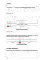
3.1 Parity Error
If you enable the parity error injection,the parity bit in the nomal word will be chang to
negative artificially. The Figure 3-1 show you the definition of the Parity Error in the
32bits word. The Parity Error in the 25bits word is defined in the same way.
Figure 3-1 Parity Error(32bit)
3.2 Gap Error
According to the ARINC429 protocol, the gaps between two words is 4 Null bits at least, in
EMBC1000-USB429EI-42, the way to inject Gap error into transmit data is to make the
Gap time between two words is 2 Null bits, Shown in Figure 3-2:
Figure 3-2 Gap Error(32bit)
3.3 Short Word Error
ShortWord Error is also called “Break Error”, means the data was send not enough 32/25
bits, just like the data frame is broken, In EMBC1000-USB429EI-42, the way to inject the
shortword error into the transmit data is cut down two bits which replace by two NULL bit,
Shown in Figure 3-3:
Orbita Control Engineering Co., Ltd.
- 7-
EMBC1000-PCI429E USER MANUAL
Figure 3-3 Short Word Error(32bit)
3.4 Long Word Error
ILong Word Error is also called “Long Frame Error”.It means the word sending contain
34/27 bits.If you enable the Long Wordd error injection, the 2 bits ”00” will be add to
nomal word(32 bits or 25 bits).The Figure 3-4 show you the definition of the Long Word
Error in the 32bits word. The Long Word Error in the 25bits word is defined in the same
way.
Figure 3-4 Long Word error(32bit)
Orbita Control Engineering Co., Ltd.
- 8-
EMBC1000-PCI429E USER MANUAL
CHAPTER 4 OPERATIONS AND SETUP
4.1 HARDWARE and its drivers INSTALLATION
4.1.1
Hardware installation
EMBC1000-PCI429 card is designed to be inserted directly into any PCI 2.1, or higher,
compatible slot of PC.
Note: When installing the card, the following cautions must be taken:
1)
NEVER insert or remove the card with the power turned on.
2)
ALWAYS take proper precautions to guard against static damage. Use a
wrist strap if available, or ensure proper static grounding by touching the
power supply cover with power OFF.
3)
Insert the card gently into the motherboard slot. Secure with proper
hardware.
4)
Make sure that adjacent cabling and wiring do not hinder the airflow
around the card.
Once the PCI card gets installed into your PC and proper connections are made
between ARINC429 target hardware and PCI card via the DB25 connector, then the
hardware installation gets basically done. Congratulations!
NOTE: Please be advised that you should assign a number to each PCI card (we
called Board Number in our setup software) you inserted into the system according
to the sequential order of the PCI slots in your system. If only ONE PCI card be
inserted in your system, then the Board Number is 0. If there are more than one PCI
card installed into your system, you should assign a number (valid 0-255) to each
board according to the location of each PCI slot in the system. When the application
software is used, it must be configured with each board, though mutliple boards can
work together.
However, before you could use this card, you need to install drivers software from the
provided CD-ROM onto your PC: board oriented drivers and LIB oriented drivers,
which are designed to run under Windows XP or Windows 2000.
4.1.2
Board oriented drivers Installation
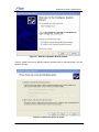
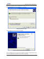
Once the card gets installed and the PC is turned ON, the PC shall perform automatic
detection for the card inserted. If the drivers have not been installed yet, it will treat the
card to be a new hardware and, it will report to you right away by bringing up “Add New
Hardware Wizard” to guide you for the installation of the required drivers.
Orbita Control Engineering Co., Ltd.
- 9-
EMBC1000-PCI429E USER MANUAL
Figure 4-1 Add New Hardware Wizard window
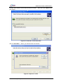
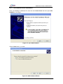
Click on “Install from a list or specific location” and then click on the Next button, you will
asked to choose:
Figure 4-2 choose the driver to install
Orbita Control Engineering Co., Ltd.
- 10-
EMBC1000-PCI429E USER MANUAL
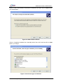
Choose “Don’t search.I will choose the driver to install”,
you will get:
then click on the Next button,
Figure 4-3 select the .inf file from disk
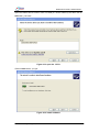
click on “Have Disk… “button, you will enter the next window:
Figure 4-4 open the .inf file
Orbita Control Engineering Co., Ltd.
- 11-
EMBC1000-PCI429E USER MANUAL
Browse the CD-ROM, open the EMBC1000-PCI429EI_device.inf from CD_ROM (G:\
driver\ boarddriver) and click on OK button, you will get:
Figure 4-5 open the .inf file
Click on Next button to have the driver installed.
Figure 4-6 finish the board drivers installation
Click on Finish button to complete this installation procedure. Congratulations! Now
you have installed the board drivers onto your PC successfully.
Orbita Control Engineering Co., Ltd.
- 12-
EMBC1000-PCI429E USER MANUAL
4.1.3
LIB oriented drivers Installation
From your desktop of Windows XP, enter into the Control Panel and then open Add
Hardware, you will get:
Figure 4-7 open Add Hardware
Click on Next button, you enter:
Figure 4-8 Add Hardware Wizard
Orbita Control Engineering Co., Ltd.
- 13-
EMBC1000-PCI429E USER MANUAL
Click on “Yes,I have already connected the hardware”,and then click on Next button,
you will be asked:
Figure 4-9 Add Hardware Wizard
Click on “install the hardware that I manually select from a list”,and then click on Next
button, you will get:
Figure 4-10 select the type of hardware
Orbita Control Engineering Co., Ltd.
- 14-
EMBC1000-PCI429E USER MANUAL
Click on Next button, you enter the window below.
Figure 4-11 select the .inf file from disk
Click on Have Disk… button, you will see:
Figure 4-12 open the .inf file
Orbita Control Engineering Co., Ltd.
- 15-
EMBC1000-PCI429E USER MANUAL
Open the EMBC1000-PCI429.inf from CD-ROM (G:\ driver\ LIBdriver) and then click on
OK button, you enter:
Figure 4-13 open the .inf file
Click on Next button, you get:
Figure 4-14 install hardware
Orbita Control Engineering Co., Ltd.
- 16-
EMBC1000-PCI429E USER MANUAL
Click on Next button to have the LIB drivers installed.
Figure 4-15 finish the LIBdriver installing
Click on Finish button to complete this installation procedure. Congratulations! Now
you have installed the LIB drivers onto your PC successfully.
HINT: Check if the hardware drivers get installed properly
Yes, you can simply open the Device Manager to check. If both board drivers and LIB
drivers gets installed properly, they shall be displayed under device group Jungo as
below:
Figure 4-16 hardware install successfully
Orbita Control Engineering Co., Ltd.
- 17-
EMBC1000-PCI429E USER MANUAL
4.2
Get started with the Application Software
Once the HARDWARE INSTALLATION gets done successfully, EMBC1000-PCI429EI
card is ready to use.
Each PCI card should be assigned a number (we called Board Number in our setup
software) according to the sequential order of the PCI slots in your system. If only ONE
PCI card be inserted in your system, then the Board Number is 0. If there are more than
one PCI card installed into your system, you should assign a proper number (valid 0-255)
to each board according to the location of each PCI slot in the system. When the
application software is used, it must be configured with each board with the specified
Board Number, though mutliple boards can work together.
Double click on the application software EMBC1000-PCI429EI.exe
ApplicationSoftware),you will see the software startup Logo:
(G:\
Figure 4-17 software startup Logo
After about 10 seconds, the “Select Board Number” window will popup. The ”Board
Number” means the application software will only opration this card. When multiple
cards in one system,the user should open multiple application software to operate the
cards. The user should get the value of “Board Number” from the PCI slot which the
card inserted.If only one card in the system, the “Board Number” is 0.
Now you should enter the ”Board Number" (possible assignment value range: 0 to 255)
of the PCI card. Click on OK button after the number gets entered.
Figure 4-18 Select Board Number
Orbita Control Engineering Co., Ltd.
- 18-
EMBC1000-PCI429E USER MANUAL
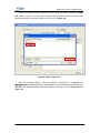
If the “Board Number” you entered is incorrect or the hardware drivers have not been
installed properly, you will observe the Error information window as below. In this case,
you should double check if the PCI card is in proper working mode or if the card is
numbered properly.
Figure 4-19 Error prompt
If Board Number is properly specified and the PCI card works well with the system, the
application software will be launched and its main window will be opened as below.
Figure 4-20 main window of the application software
Orbita Control Engineering Co., Ltd.
- 19-
EMBC1000-PCI429E USER MANUAL
4.3 Parameters Setup
4.3.1
Rx Channel Parameter Setup
Click the “RX-1234”, you will enter the parameters setup page of Rx channels, shown in
Figure 4-21.
Setup Rx channel Parameters
Save the parameters as RX_SETTING.txcfg file
Figure 4-21 Rx channel parameters setup
Now you are free to set the Rx channel parameters, such as: Word length,Baudrate,
Parity check, SDI check, Lable check, etc.. After changing the parameter, you must
press the “Apply setting” button to make it valid, and the configuration can be saved into
a data file by pressing the “Save Setting” button, and an existing configuration can be
loaded from a file by pressing the “load setting” button.
Note: User must press the “Apply setting” button to enable the changes to parameters.
Possible assignment value for each parameter
Under the receive (Rx) channel parameter setup window, the content of each parameter
Orbita Control Engineering Co., Ltd.
- 20-
EMBC1000-PCI429E USER MANUAL
can be selected by pulling down the respective menu bar. The contents of each
parameter are listed below.
Table 4-1 Possible Assignment Value For Each Rx Parameter
Menu Item
Possible assignment value
Default
Word Length
32, 25 bit
32
Baud Rate
12.5, 48, 50, 100 Kbps
12.5
Parity Check
Disable, odd, even
Disable
SDI Decode
Disable, 00,01,10,11 (binary)
Disable
Label Check
Disable, enable
Disable
L1
0~0xFF
00
L2
0~0xFF
00
L3
0~0xFF
00
L4
0~0xFF
00
L5
0~0xFF
00
L6
0~0xFF
00
L7
0~0xFF
00
Buttons on Rx parameters setup page description:
“Slect channel”: Select a singel Rx channel or multiple
channles which you want to change the parameters.
“Save Setting”: button: Save the Rx configuration into a txt file.
“Load Setting”: button: Load Rx configuration from a exiting txt file.
“Apply Setting”: button: Enabel the parameter changes.
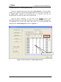
If the Rx parameters setup done, you can observe it from the pulldown bar:
Figure 4-22
Parameter setting display
Once the Rx channel parameters get setup, each Rx channel will perform data
receiving operations strictly according to the data format defined in the setup.
Orbita Control Engineering Co., Ltd.
- 21-
EMBC1000-PCI429E USER MANUAL
4.3.2
Tx Channel Parameter Setup
Click the “TX-1” button, you will enter the parameters setup page of the first Tx channel
channel, shown in Figure 4-23.
Tx-1 channel Parameters setup
Save the parameters as TX1_SETTING.txcfg
Figure 4-23 setup transmit channels’ parameter
In this window, you are free to change the Tx channel parameter such as: word length,
baud rate, parity, word gap, repetition mode, error injiection and the work mode such as:
“Normal mode” or “Loopback mode”. In the loopback mode, EMBC1000-PCI429EI can
only receive the data from the internal Tx channels of the device, data from external
target will be ignored. The configuration can be saved into a data file by pressing the
“Save Setting” button, and an existing configuration can be loaded from a file by
pressing the “load setting” button.
In the Repetition Mode, if “enable” is selected, the current data in “send data” area will
be tramsitted repeatedly. The interval time between 2 sequential words is specified
by ”Time gap” (ranged from 1 to 99,999,999 us), the repetition transmit will be
terminated by press the “stop” button in “send data” area. In the Repetition Mode, if
“disable” is selected, the current data will only be sent one time.
Orbita Control Engineering Co., Ltd.
- 22-
EMBC1000-PCI429E USER MANUAL
Note: User must click on the “Apply Setting” button to to make any parameter changes
effecticve.
Click on the “TX-2”, you will enter the parameters setup window for transmit channel
(Tx-2). The setting for this channel is identical to TX-1’s.
Possible assignment value for each parameter
Under the trasimit (Tx) channel parameter setup window, the content of each parameter
can be selected by pulling down the respective menu bar. The contents of each
parameter are listed below.
Table 4-2 Possible Assignment Value For Each Tx Parameter
Menu Item
Possible assignment value
Default
Word Length
32, 25
32
Baud Rate
12.5, 48, 50, 100
12.5
Parity Check
Disable, odd, even
Disable
Word Gap
5 ~ 255
10
Work Mode
Normal, Loopback
Normal
Repetition Mode *
Disable, Enable
Disable
Error injection **
Parity/Gap/Short Word/Long Word Error
No error injecting
Time gap ***
1 ~ 99,999,999 us
100 us
* The max number of data can be transmitted under Repetition Mode is 1024.
* The max number of data can be transmitted under Repetition Mode is 1024.
** You are free to inject the errors:
Parity error: the parity bit of the data will be opposite to the bit you defined.
Gap error: set the word gap to be 2 bit times;
Short word error: only send 30/23 bits in one word(32/25bit).
Long word error: send 34/27 bits in one word(32/25bit)..
Note: only of those error(gap error, short word error, long word error) can be injected at the same time.
*** Refers to the time gap between two Repetition transmits. Time gap can only be
assigned a value when Repetition Mode is under “Enable”.
Orbita Control Engineering Co., Ltd.
- 23-
EMBC1000-PCI429E USER MANUAL
4.4 Data Transmission Operations
After the parameter setup is finished, the user can add the data into the “Send data”
area for data transmission operations (by pressing “Send” button under the data
transmit window).
The user can add the data into the “Send data” area, either in single or bulk mode.
In single mode, there is a dedicated data entry area under “Single add”, where one may
simply put a digital number (in Hex) into the field of “WORD(H)”, or he may define the
following detailes to compose a WORD to be sent: PAR(B), SDI(B), SSM(B), LAB(H),
Data(H), which represents Parity, SDI check bits, SSM bits, Lable check and Data.
Table 4-3
The fields definition of Tx data
Field
Range
WORD(HEX)
0x00000000~0xFFFFFFFF
PAR(Binary)
0,1
SDI (Binary)
00,01,10,11
SSM (Binary)
00,01,10,11
LAB(HEX)
0x0~0xFF
DATA(HEX)
0x000000~0x7FFFF
In bulk mode, there is a dedicated data entry area under “Bulky add”, where one may
simply create a base digital number (in Hex, here we defined it to ”Begin Data”), and
define the increment and the toal number of data in the respective field, then it will
automatically generate a set of data.
It is also possible for the user to use single mode entry method repeatedly to generate a
set of data (bulk data) to tranmit.
For any data added into this field, it can be saved into a data file by pressing the “Save”
button, and an existing data file can be loaded in pressing the “Load” button.
The user can press “Clear” button to clear all the data which have addedd in the “Send
data” area. If you want to delete one word from the data added in the “Send data” area,
you should select it and then press “Delete” button.
Each time, the total number of WORDs added shall counted and be displayed in the
“All” field. And the total number of WORDs transmitted via this transmit channel shall be
counted and displayed in the “Send Num” field.
Data transmission can be terminated any time by pressing “Stop” button.
Orbita Control Engineering Co., Ltd.
- 24-
EMBC1000-PCI429E USER MANUAL
1)
Add single Tx data in WORD field
enter a single data with WORD
Press ADD to add single data, and
the attributes to be created and
displayed automatically.
The total number of words added
Figure 4-24 Add single data with WORD field
Orbita Control Engineering Co., Ltd.
- 25-
EMBC1000-PCI429E USER MANUAL
2)
Add single data in attribute fields
Press ADD to generate a WORD
Enter a single data with attributes
and to add it into the Send data
area and to display it in the area
A single word is added into
the “Send data” area, and is
displayed here.
The total number of words added
Figure 4-25 Add single data with attribute fields
Orbita Control Engineering Co., Ltd.
- 26-
EMBC1000-PCI429E USER MANUAL
3) Add Bulk data
Press ADD button
to add bulk data
Define a set of date
The total number
of words added
The total number of WORDs
transmitted via this channel(TX1)
Figure 4-26 Add Bulky data
Attention: about the Data Format
The standard ARINC429 Data Word Format is different from the format of the data in
the “Send data” or “Receive data” area, show in Figure 4-27 and Figure 3-28 .
Orbita Control Engineering Co., Ltd.
- 27-
EMBC1000-PCI429E USER MANUAL
Figure 4-27 Mapping of ARINC429 Data in 32-bit Format
Figure 4-28 Mapping of ARINC429 Data in 25-bit Format
Orbita Control Engineering Co., Ltd.
- 28-
EMBC1000-PCI429E USER MANUAL
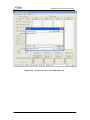
4.5 Data Receiving Operations
Data Receiving Operation is quite simple. Once the Rx channel parameter setup gets
done, then the user can simply press “RX-1 Start”/“RX-2 Start”/“RX-3 Start”/“RX-4 Start”
button to enable the RX1/RX2/RX3/RX4 channel to start to receive data from the
connected ARINC429 target hardware. It is also very important that the communication
protocols between target hardware and this card should be defined the same.
Please be advised that “RX-1 Start”/“RX-2 Start”/“RX-3 Start”/“RX-4 Start” buttons can
be toggled. Once you press “RX-1 Start”/“RX-2 Start”/“RX-3 Start”/“RX-4 Start” once,
it will be toggled into “RX-1 Stop”/“RX-2 Stop”/“RX-3 Stop”/“RX-4 Stop”.
To terminate Data Receiving operation, simply pressing “RX-1 Stop”/“RX-2 Stop”/“RX-3
Stop”/“RX-4 Stop” buttons again and, all buttons will then be toggled to “RX-1
Start”/“RX-2 Start”/“RX-3 Start”/“RX-4 Start” mode.
The data received and the total number of the data received will be displayed in the
“Receive Data” area. It is advised that the “Receive Data” area only display 3000 words
max. When more than 3000 words received, only the last 3000 words can be displayed.
The user can press “RX-1 Save”/“RX-2 Save”/“RX-3 Save”/“RX-4 Save” button to
create a .txt data file to save all data received before pressing “RX-1 Start”/“RX-2
Start”/“RX-3 Start”/“RX-4 Start” button. Once the .txt data file created, then all data
received will be saved into this .txt file for later analysis. The .txt data file can not be
created if Data Receiving operation is still in progress.
The user can clear the data displayed on the “Receive Data” area by pressing “RX-1
Clear”/“RX-2 Clear”/“RX-3 Clear”/“RX-4 Clear” button.
The user can enable the automatic error detection function by selecting the
button--“Error Detection”. And the error will be display on the “Receive Data” area, and
the total number of the error detected will be display on the “Error Detection” area. The
user can clear them by pressing “RX-1 Clear”/“RX-2 Clear”/“RX-3 Clear”/“RX-4 Clear”
button.
Orbita Control Engineering Co., Ltd.
- 29-
EMBC1000-PCI429E USER MANUAL
Figure 4-29
Create a .txt file to save Data Received
Orbita Control Engineering Co., Ltd.
- 30-
EMBC1000-PCI429E USER MANUAL
Figure 4-30 Data Receiving operations(Disable automatic error detection )
4.6 Error injection and error detection Operation
4.6.1 Transmit error injection
The user can enable the error injection when she doing the tx channel parameters
setup.The user can selet parity error, gap error, short word error, long word error(Figure
4-35) to inject into the data transmit.
You are free to inject the errors:
1. Parity error: the parity bit of the data will be opposite to the bit you defined;
2. Gap error: set the word gap to be 2 bit times;
3. Short Word error: only send 30/23 bits in one word(32/25bit);
4. Long Word error: send 34/27 bits in one word(32/25bit).
Note: only of those error(gap error, short word error, long word error) can be injected at
the same time.
Orbita Control Engineering Co., Ltd.
- 31-
EMBC1000-PCI429E USER MANUAL
Step about data receiving with automatic error detection:
1. Do parameter setup,just as the Word Length, Baud Rate, Parity Check, Work Mode,
Error Injection, Repetition and so on;
2. Press the “Apply setting” button to enable the changes to parameters;
3. Add the data you want to send;
4. Press the “Send” buttons to send the data you added.
Error Injection define
Press it to send data
Figure 4-35 Error injection operation
Note: User must press the “Apply Setting” button to to make the error injection
effecticve.
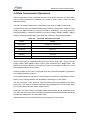
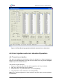
4.6.2 Automatic error detection in receive channels
Some error ( such as: Parity Error, Gap Error, Short Word Error, Long Word Error)
can be automatic detected when you enable the automatic error detection by select the
button-- “Error Detection”.
Orbita Control Engineering Co., Ltd.
- 32-
EMBC1000-PCI429E USER MANUAL
Step about data receiving with automatic error detection:
1. Do parameter setup,just as the Word Length, Baud Rate, Parity Check, SDI Decode,
Label Check and so on;
2. Select the channel which you want to it’s parameters;
3. Press the “Apply setting” button to enable the changes to parameters;
4. Select the the “Error Detection” button to enable the error detection function, each
channel has its own “Error Detection” button;
5. Press the “RX-1 Start”/“RX-2 Start”/“RX-3 Start”/“RX-4 Start” buttons to begin the
Data Receiving operation.
Once some error detect from the receiving data, they will be display on the “Receive
Data” area(just as: PE, GE, SE, LE, PG), and the total number of the error detected will
be display on the “Error Detection” area. The user can clear them by pressing “RX-1
Clear”/“RX-2 Clear”/“RX-3 Clear”/“RX-4 Clear” button.
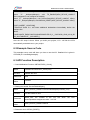
Table 4-4 Error detect form Receiving data
Error
Error description
PE
Parity Error
GE
Gap Error
SE
Short Word Error
LE
Long Word Error
PG
Parity and Gap Error
Orbita Control Engineering Co., Ltd.
- 33-
EMBC1000-PCI429E USER MANUAL
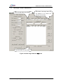
Error Display
parameters setup
Error Statistic.
Figure 4-32 error detection operation
Orbita Control Engineering Co., Ltd.
- 34-
EMBC1000-PCI429E USER MANUAL
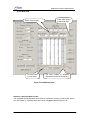
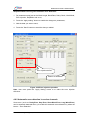
CHAPTER 5 Data Analysis Software
The ARINC429 data received can be analyzed with the provided Data Analysis
software. The software will deal with the data either saved in the .txt data file or in the
data field entered on-line.
Double click on the software Data Convert.exe(G:\DataAnalysis), you will see the main
window showed in Figure 5-1.
Figure 5-1 main window of Data Convert
The software will deal with the data either saved in the .txt data file or in the data
operation field entered on-line.
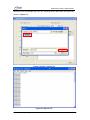
1) Data Conversion from a Data File
In this way, user can analyze the ARINC429 data saved in the *.txt file (assume Source
File.txt).
Click the “Source File” button to open the data file.
The ARINC429 data saved in the Source File are in Hex, the first line is always the
Orbita Control Engineering Co., Ltd.
- 35-
EMBC1000-PCI429E USER MANUAL
definition of the word length (25 or 32 bit), following are the data (each word per line) ,
shown in Figure 5-3.
Figure 5-2 open a source file
Figure 5-3 Source File
Orbita Control Engineering Co., Ltd.
- 36-
EMBC1000-PCI429E USER MANUAL
Then, you need to create a target file to save such conversion. Click the “Target
File” button to open a *.txt file (assume Target File.txt) which saved the results of the
analysis (actually, conversion results so far), shown in Figure 5-4.
Figure 5-4 open Target File
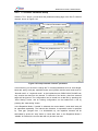
Click the “Convert” button, when the analysis (conversion) is completed, the
“Convert number” area will show the total number of the words analysed. And then you
can open the Target File(Target File.txt) to study the results, shown in Figure 5-5 and
Figure 5-6.
Orbita Control Engineering Co., Ltd.
- 37-
EMBC1000-PCI429E USER MANUAL
Figure 5-5 Conversion completed
Figure 5-6 Target File
Orbita Control Engineering Co., Ltd.
- 38-
EMBC1000-PCI429E USER MANUAL
2) Data Conversion in Data Operation field
There is a dedicated data entry area under “Data Operation”. One may simply
create a set of data by using the base digital number (in Hex, here we termed it to
be ”Begin Data”), defining the increment(accept 0 to 0xFFFFF) and the toal
number(accept 0 to 65535) of data in the respective field.
Once the data is configured, you may click on the “Convert” button, it will
automatically generate a set of data and perform conversion over them automatically.
The attributes such as PAR, SDI, SSM, LAB, DATA, etc. will be generated and
displayed in the ”Data Display Area”, shown in Figure 5-7.
Data Display Area
Figure 5-7 data conversion in Data Operation field
Orbita Control Engineering Co., Ltd.
- 39-
EMBC1000-PCI429E USER MANUAL
CHAPTER 6 Develop Your own Application Software
To allow the user to develop his own application software or project,
EMBC1000-PCI429EI card comes with drivers software, API (Application Programming
Interface) library and user oriented application software, running under Windows 2000
or Windows XP. The user oriented application software has been designed with the
capabilities of simulating the outputs of various airborne systems, receiving inputs from
these systems, and providing bus data analysis functions. API library is also provided
together with example source code (Visual C++), which allow users to easily develop
their own application software or project based on the real world applications.
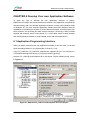
6.1 Application Programming Interface
When you begin to develop your own application software for this PCI card, you should
finish the settings below in you project(build in Visual C++ 6.0):
Copy PCI_LINK3.dll, PCI_LINK3.lib, wdapi901.dll, wdapi901.lib (you can find them in
CD-ROM\UserDesign\APILibrary) to your project working directory.
Add the PCI_LINK3.lib and wdapi901.lib to the project: ProjectÆSettingÆLink, shown
in Figure 6-1:
Figure 6-1 Add the PCI_LINK3.lib and wdapi901.lib to the project
Orbita Control Engineering Co., Ltd.
- 40-
EMBC1000-PCI429E USER MANUAL
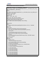
Edit the head file, refer to the source code below:
// EMBC1000-PCI429-42-exampleDlg.h : header file
#if !defined(AFX_EMBC1000PCI42942EXAMPLEDLG_H__5ACC0538_C64A_4316_8
DDD_9A1CA8B3A7CF__INCLUDED_)
#define
AFX_EMBC1000PCI42942EXAMPLEDLG_H__5ACC0538_C64A_4316_8DDD_9A1C
A8B3A7CF__INCLUDED_
#if _MSC_VER > 1000
#pragma once
#endif // _MSC_VER > 1000
typedef void * WDC_DEVICE_HANDLE;
/////////////////////////////////////////////////////////////////////////////
// CEMBC1000PCI42942exampleDlg dialog
class CEMBC1000PCI42942exampleDlg : public CDialog
{
// Construction
public:
CEMBC1000PCI42942exampleDlg(CWnd* pParent = NULL); //standard
constructor
// Dialog Data
//{{AFX_DATA(CEMBC1000PCI42942exampleDlg)
enum { IDD = IDD_EMBC1000PCI42942EXAMPLE_DIALOG };
//}}AFX_DATA
// ClassWizard generated virtual function overrides
//{{AFX_VIRTUAL(CEMBC1000PCI42942exampleDlg)
protected:
virtual void DoDataExchange(CDataExchange* pDX); // DDX/DDV support
//}}AFX_VIRTUAL
// Implementation
protected:
HICON m_hIcon;
// Generated message map functions
//{{AFX_MSG(CEMBC1000PCI42942exampleDlg)
virtual BOOL OnInitDialog();
afx_msg void OnSysCommand(UINT nID, LPARAM lParam);
afx_msg void OnPaint();
afx_msg HCURSOR OnQueryDragIcon();
afx_msg void OnInit();
afx_msg void OnTX1Init();
afx_msg void OnTX2Init();
afx_msg void OnRX1Init();
afx_msg void OnRX2Init();
afx_msg void OnRX3Init();
afx_msg void OnRX4Init();
Orbita Control Engineering Co., Ltd.
- 41-
EMBC1000-PCI429E USER MANUAL
afx_msg void OnSendDataTX2();
afx_msg void OnSendDataTX1();
afx_msg void OnClose();
afx_msg void OnRxread();
afx_msg void OnRx1read();
afx_msg void OnRx2read();
afx_msg void OnRx3read();
afx_msg void OnRx4read();
//}}AFX_MSG
DECLARE_MESSAGE_MAP()
};
#pragma comment(lib,"PCI_LINK3.lib")
extern "C" _declspec(dllexport) WDC_DEVICE_HANDLE DeviceFindAndOpen(int
Board_num);
extern "C" _declspec(dllexport) DWORD OBT429TOPCI_LibInit(void);
extern "C" _declspec(dllexport)
int RX_DATA( WDC_DEVICE_HANDLE hDev,
unsigned int RX_N, unsigned int RX_DATA[256], unsigned int fifo_leve);
extern "C" _declspec(dllexport)
int TX1_SEND(WDC_DEVICE_HANDLE hDev,
unsigned int txdata[64], int fifo_leve);
extern "C" _declspec(dllexport)
int TX2_SEND(WDC_DEVICE_HANDLE hDev,
unsigned int txdata[64], int fifo_leve);
extern "C" _declspec(dllexport) void RX1_INIT(WDC_DEVICE_HANDLE hDev,
unsigned int enable,
// (0, 1)
unsigned int word_length,
// (25, 32)
unsigned int parity_select, // (0,1,2)
unsigned int label_enable, // (0,1)
unsigned int sdi,
// (0,1)
unsigned int scaler,
// (0~65535)
unsigned int label1,
unsigned int label2,
unsigned int label3,
unsigned int label4,
unsigned int label5,
unsigned int label6,
unsigned int label7
);
extern "C" _declspec(dllexport) void RX2_INIT(WDC_DEVICE_HANDLE hDev,
unsigned int enable,
// (0, 1)
unsigned int word_length,
// (25, 32)
unsigned int parity_select, // (0,1,2)
unsigned int label_enable, // (0,1)
unsigned int sdi,
// (0,1)
unsigned int scaler,
// (0~65535)
unsigned int label1,
Orbita Control Engineering Co., Ltd.
- 42-
EMBC1000-PCI429E USER MANUAL
unsigned int label2,
unsigned int label3,
unsigned int label4,
unsigned int label5,
unsigned int label6,
unsigned int label7
);
extern "C" _declspec(dllexport) void RX3_INIT(WDC_DEVICE_HANDLE hDev,
unsigned int enable,
// (0, 1)
unsigned int word_length,
// (25, 32)
unsigned int parity_select, // (0,1,2)
unsigned int label_enable, // (0,1)
unsigned int sdi,
// (0,1)
unsigned int scaler,
//
unsigned int label1,
unsigned int label2,
unsigned int label3,
unsigned int label4,
unsigned int label5,
unsigned int label6,
unsigned int label7
);
extern "C" _declspec(dllexport) void RX4_INIT(WDC_DEVICE_HANDLE hDev,
unsigned int enable,
// (0, 1)
unsigned int word_length,
// (25, 32)
unsigned int parity_select, // (0,1,2)
unsigned int label_enable, // (0,1)
unsigned int sdi,
// (0,1)
unsigned int scaler,
// (0~65535)
unsigned int label1,
unsigned int label2,
unsigned int label3,
unsigned int label4,
unsigned int label5,
unsigned int label6,
unsigned int label7
);
extern "C" _declspec(dllexport) void TX1_INIT(WDC_DEVICE_HANDLE hDev,
unsigned int enable, unsigned int word_length, unsigned int parity, unsigned int scaler,
unsigned int tgap, unsigned int mode);
extern "C" _declspec(dllexport) void TX2_INIT(WDC_DEVICE_HANDLE hDev,
unsigned int enable, unsigned int word_length, unsigned int parity, unsigned int scaler,
unsigned int tgap, unsigned int mode);
extern
"C"
_declspec(dllexport)
void
RX_ENABLE(WDC_DEVICE_HANDLE
Orbita Control Engineering Co., Ltd.
- 43-
EMBC1000-PCI429E USER MANUAL
hDev,unsigned int num,unsigned int enable);
extern
"C"
_declspec(dllexport)
void
TX_ENABLE(WDC_DEVICE_HANDLE
hDev,unsigned int num,unsigned int enable);
extern "C" _declspec(dllexport) void DeviceClose(WDC_DEVICE_HANDLE hDev);
extern "C" _declspec(dllexport) void OBT429_RESET(WDC_DEVICE_HANDLE hDev);
//{{AFX_INSERT_LOCATION}}
// Microsoft Visual C++ will insert additional declarations immediately before the
previous line.
#endif
// !defined(AFX_EMBC1000PCI42942EXAMPLEDLG_H__5ACC0538_C64A_4316_8D
DD_9A1CA8B3A7CF__INCLUDED_)
Now the API setup is done. When you build your project, VC++ will link the APIs
automatically and add them to your project.
6.2 Example Source Code
This example source code will show you how to use the API. Detailed info is given in
CD-ROM (G:\ UserDesign\sample).
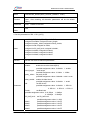
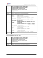
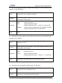
6.3 API Function Description
1. Card Initialization Function: OBT429TOPCI_LibInit()
Name
DWORD OBT429TOPCI_LibInit(void)
Function
Initialize the card
Parameter
Void
Return
Value
DWORD
2. Getting the handle: DeviceFindAndOpen()
Name
WDC_DEVICE_HANDLE DeviceFindAndOpen(int Board_num)
Function
Get the handle of card
Parameter
Board_num: the number of the PCI slot
insertedpossible assignment value : 0 to 255
Return
Value
WDC_DEVICE_HANDLE hDevX
which
the
card
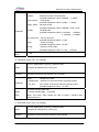
3. Reset the card: OBT429_RESET()
Orbita Control Engineering Co., Ltd.
- 44-
EMBC1000-PCI429E USER MANUAL
Name
void OBT429_RESET(WDC_DEVICE_HANDLE
hDev)
Function
Reset the card
(Note:After resetting, all channels’ parameters will be the default
value.)
Parameter
hDev:
Return
Value
void
handle of the card
4. Set the parameters of RX-1: RX1_INIT()
Name
void RX1_INIT(WDC_DEVICE_HANDLE hDev,
unsigned int enable, unsigned int word_length,
unsigned int parity_select,unsigned int label_enable,
unsigned int sdi,unsigned int scaler,
unsigned int fifo_half_level, unsigned int label1,
unsigned int label2, unsigned int label3,
unsigned int label4, unsigned int label5,
unsigned int label6, unsigned int label7
)
Function
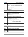
Set the first receive channel’s parameters
hDev:
enable:
Parameter
handle of the card
enable the receive channel(RX1)
possible assignment value : 0:disable 1: enable
word_length:
word length
possible assignment value : 0:32bits 1: 25bits
parity_select: set parity check
possible assignment value: 0:disable 1: odd 2: even
label_enable: enable the label check
possible assignment value : 0:disable 1: enabl
sdi:
set SDI check
possible assignment value : 0:disable 1: SDI=00
2: SDI=01 3: SDI=10 4: SDI=11
Scaler:
set Buad rate
possible assignment value : 0:12.5Kbps 1: 48Kbps
2: 100Kbps 3: 50Kbps
fifo_half_level: set fifo_half level
possible assignment value: 0~1023
label1:
possible assignment value: 0~0xFF
label2:
possible assignment value: 0~0xFF
label3:
possible assignment value: 0~0xFF
label4:
possible assignment value: 0~0xFF
Orbita Control Engineering Co., Ltd.
- 45-
EMBC1000-PCI429E USER MANUAL
label5:
label6:
label7:
Return
Value
possible assignment value: 0~0xFF
possible assignment value: 0~0xFF
possible assignment value: 0~0xFF
void
5. Set the parameters of RX-2: RX2_INIT()
Name
void RX2_INIT(WDC_DEVICE_HANDLE hDev,
unsigned int enable, unsigned int word_length,
unsigned int parity_select,unsigned int label_enable,
unsigned int sdi,unsigned int scaler,
unsigned int fifo_half_level, unsigned int label1,
unsigned int label2, unsigned int label3,
unsigned int label4, unsigned int label5,
unsigned int label6, unsigned int label7
)
Function
Set the second receive channel’s parameters
hDev:
enable:
Parameter
Return
Value
handle of the card
enable the receive channel(RX2)
possible assignment value: 0:disable 1: enable
word_length:
word length
possible assignment value: 0:32bits 1: 25bits
parity_select: set parity check
possible assignment value: 0:disable 1: odd 2: even
label_enable: enable the label check
possible assignment value: 0:disable 1: enabl
sdi:
set SDI check
possible assignment value: 0:disable 1: SDI=00
2: SDI=01 3: SDI=10 4: SDI=11
Scaler:
set Buad rate
possible assignment value: 0:12.5Kbps 1: 48Kbps
2: 100Kbps 3: 50Kbps
fifo_half_level: set fifo_half level
possible assignment value: 0~1023
label1:
possible assignment value: 0~0xFF
label2:
possible assignment value: 0~0xFF
label3:
possible assignment value: 0~0xFF
label4:
possible assignment value: 0~0xFF
label5:
possible assignment value: 0~0xFF
label6:
possible assignment value: 0~0xFF
label7:
possible assignment value: 0~0xFF
void
Orbita Control Engineering Co., Ltd.
- 46-
EMBC1000-PCI429E USER MANUAL
6. Set the parameters of RX-3: RX3_INIT()
Name
void RX3_INIT(WDC_DEVICE_HANDLE hDev,
unsigned int enable, unsigned int word_length,
unsigned int parity_select,unsigned int label_enable,
unsigned int sdi,unsigned int scaler,
unsigned int fifo_half_level, unsigned int label1,
unsigned int label2, unsigned int label3,
unsigned int label4, unsigned int label5,
unsigned int label6, unsigned int label7
)
Function
Set the third receive channel’s parameters
hDev:
enable:
Parameter
Return
Value
handle of the card
enable the receive channel(RX3)
possible assignment value: 0:disable 1: enable
word_length:
word length
possible assignment value: 0:32bits 1: 25bits
parity_select: set parity check
possible assignment value: 0:disable 1: odd 2: even
label_enable: enable the label check
possible assignment value: 0:disable 1: enabl
sdi:
set SDI check
possible assignment value: 0:disable 1: SDI=00
2: SDI=01 3: SDI=10 4: SDI=11
Scaler:
set Buad rate
possible assignment value: 0:12.5Kbps 1: 48Kbps
2: 100Kbps 3: 50Kbps
fifo_half_level: set fifo_half level
possible assignment value: 0~1023
label1:
possible assignment value: 0~0xFF
label2:
possible assignment value: 0~0xFF
label3:
possible assignment value: 0~0xFF
label4:
possible assignment value: 0~0xFF
label5:
possible assignment value: 0~0xFF
label6:
possible assignment value: 0~0xFF
label7:
possible assignment value: 0~0xFF
void
7. Set the parameters of RX-4: RX4_INIT()
Orbita Control Engineering Co., Ltd.
- 47-
EMBC1000-PCI429E USER MANUAL
Name
void RX4_INIT(WDC_DEVICE_HANDLE hDev,
unsigned int enable, unsigned int word_length,
unsigned int parity_select,unsigned int label_enable,
unsigned int sdi,unsigned int scaler,
unsigned int fifo_half_level, unsigned int label1,
unsigned int label2, unsigned int label3,
unsigned int label4, unsigned int label5,
unsigned int label6, unsigned int label7
)
Function
Set the fourth receive channel’s parameters
hDev:
enable:
Parameter
Return
Value
handle of the card
enable the receive channel(RX4)
possible assignment value: 0:disable 1: enable
word_length:
word length
possible assignment value: 0:32bits 1: 25bits
parity_select: set parity check
possible assignment value: 0:disable 1: odd 2: even
label_enable: enable the label check
possible assignment value: 0:disable 1: enabl
sdi:
set SDI check
possible assignment value: 0:disable 1: SDI=00
2: SDI=01 3: SDI=10 4: SDI=11
Scaler:
set Buad rate
possible assignment value: 0:12.5Kbps 1: 48Kbps
2: 100Kbps 3: 50Kbps
fifo_half_level: set fifo_half level
possible assignment value: 0~1023
label1:
possible assignment value: 0~0xFF
label2:
possible assignment value: 0~0xFF
label3:
possible assignment value: 0~0xFF
label4:
possible assignment value: 0~0xFF
label5:
possible assignment value: 0~0xFF
label6:
possible assignment value: 0~0xFF
label7:
possible assignment value: 0~0xFF
void
8. Set the parameters of TX-1: TX1_INIT()
Orbita Control Engineering Co., Ltd.
- 48-
EMBC1000-PCI429E USER MANUAL
Name
void TX1_INIT(WDC_DEVICE_HANDLE hDev,
unsigned int enable, unsigned int word_length,
unsigned int parity, unsigned int scaler,
unsigned int fifo_half_level, unsigned int tgap,
unsigned int mode
)
Function
Set the first transmit (TX1) channel’s parameters
hDev:
enable:
Parameter
Return
Value
handle of the card
enable the transmit channel(TX1)
possible assignment value: 0:disable 1: enable
word_length: word length
possible assignment value: 0:32bits 1: 25bits
parity_select: set parity check
possible assignment value: 0:disable 1: odd 2: even
Scaler:
set Buad rate
possible assignment value: 0:12.5Kbps 1: 48Kbps
2: 100Kbps 3: 50Kbps
fifo_half_level: set fifo_half level
possible assignment value: 0~1023
tgap:
set the word gap
possible assignment value: 4 to 255
mode:
select the work modle
possible assignment value: 0: Loop 1: Normal
Void
9. Set the parameters of TX-2: TX2_INIT()
Name
void TX2_INIT(WDC_DEVICE_HANDLE hDev,
unsigned int enable, unsigned int word_length,
unsigned int parity, unsigned int scaler,
unsigned int fifo_half_level, unsigned int tgap,
unsigned int mode
)
Function
Set the second transmit (TX2) channel’s parameters
Orbita Control Engineering Co., Ltd.
- 49-
EMBC1000-PCI429E USER MANUAL
hDev:
enable:
Parameter
Return
Value
handle of the card
enable the transmit channel(TX2)
possible assignment value: 0:disable 1: enable
word_length:
word length
possible assignment value: 0:32bits 1: 25bits
parity_select: set parity check
possible assignment value: 0:disable 1: odd 2: even
Scaler:
set Buad rate
possible assignment value: 0:12.5Kbps 1: 48Kbps
2: 100Kbps 3: 50Kbps
fifo_half_level: set fifo_half level
possible assignment value: 0~1023
tgap:
set the word gap
possible assignment value: 4 to 255
mode:
select the work modle
possible assignment value: 0: Loop 1: Normal
void
10. Send data via the TX1: TX1_SEND()
Name
int TX1_SEND(WDC_DEVICE_HANDLE hDev,
unsigned int txdata[1024], int fifo_leve
)
Function
Send dat a from the first transmit (TX1) channel
Parameter
hDev:
handle of the card
txdata[1024]: the array for the words which are going to send
fifo_leve:
the number of the words which are going to send
possible assignment value: 1 to 1024
Return
Value
0: means sending data faild
1: means sending data successful
Note: The return value should be used to judge if sending data
successfulor not.
11. Send data via the TX2: TX2_SEND()
Name
int TX2_SEND(WDC_DEVICE_HANDLE hDev,
unsigned int txdata[1024], int fifo_leve
)
Function
Send dat a from the second transmit (TX2) channel
Orbita Control Engineering Co., Ltd.
- 50-
EMBC1000-PCI429E USER MANUAL
Parameter
hDev:
handle of the card
txdata[1024]:
the array for the words which are going to send
fifo_leve:
the number of the wordswhich are going to send
possible assignment value: 1 to 1024
Return
Value
0: means sending data faild
1: means sending data successful
Note: The return value should be used to judge if sending data
successfulor not.
12. Receive data from RX-1, RX-2, RX-3, RX-4: RX_DATA()
Name
int RX_DATA( WDC_DEVICE_HANDLE hDev,
unsigned int RX_N, unsigned int RX_DATA[1024],
unsigned int RX_ER_STA[1024],
unsigned int fifo_leve
)
Function
Receive data throug 4 receive(RX1/RX2RX3/RX4) channels
Parameter
hDev:
handle of the card
RX_N:
select the receive channel
possible assignment value: 1: select RX1
2: select RX2 3: select RX3 4: select RX4
RX_DATA[1024]: the array for the words which receving from outside.
RX_ER_STA[1024]: the array for the error detect from the receving
channal shen enable the error detection.
fifo_leve:
the number of the wordswhich are going to send
possible assignment value: 1 to 1024
Return
Value
The number of the data receive
13、Releas card: DeviceClose ()
Name
Name
void DeviceClose(WDC_DEVICE_HANDLE hDev)
Close the card and release the handle of the card.
Parameter
hDev:
Return
Value
void
Orbita Control Engineering Co., Ltd.
handle of the card
- 51-
EMBC1000-PCI429E USER MANUAL
14. Check if the receive (RX1/RX2/RX3/RX4) channel’s FIFO is empty or not::
RX_FIFO_STATUS ()
Name
int RX_FIFO_STATUS(WDC_DEVICE_HANDLE hDev,
unsigned int RX_N
)
Function
Check if the receive (RX1/RX2/RX3/RX4) channel’s FIFO is empty or
not
Parameter
Return
Value
hDev:
RX_N:
handle of the card
select the receive channel
possible assignment value: 1: select RX1 2: select RX2
3: select RX3 4: select RX4
0: means the channel’s FIFO is empty
1: means the channel’s FIFO is full
2: means the channel’s FIFO is half_full (the number of the data in fifo
is bigger than the “fifo_half_level” you seted.)
Others: means some mistake,such as the TX_N is invalid.
15. Check if the transmit(TX1/2) channel’s FIFO is empty or not: TX_FIFO_STATUS ()
Name
int TX_FIFO_STATUS(WDC_DEVICE_HANDLE hDev,
unsigned int TX_N
)
Function
Check if the transmit(TX1/TX2) channel’s FIFO is empty or not
Parameter
hDev:
TX_N:
Return
Value
handle of the card
select the transmit channel
possible assignment value: 1: select TX1 2: select TX2
0: means the channel’s FIFO is empty
1: means the channel’s FIFO is empty
2: means the channel’s FIFO is half_full (the number of the data in fifo
is bigger than the “fifo_half_level” you seted.)
Others: means some mistake,such as the TX_N is invalid.
16、Reset the any channel’s FIFO: FIFO_RESET ()
Name
void FIFO_RESET(WDC_DEVICE_HANDLE hDev,
unsigned int CHANNEL
)
Function
Reset the any channel’s(RX1/RX2/RX3/RX4/TX1/TX2) FIFO
Orbita Control Engineering Co., Ltd.
- 52-
EMBC1000-PCI429E USER MANUAL
hDev:
CHANNEL:
handle of the card
select channel
possible assignment value: 1: select RX1 2: select RX2
3: select RX3 4: select RX4
5: select TX1 6: select TX2
Parameter
Return
Value
void
17、Enable the receive(RX!/RX2/RX3/RX4) channel: RX_ENABLE ()
Name
void RX_ENABLE( WDC_DEVICE_HANDLE hDev,
unsigned int num,unsigned int enable
)
Function
Enable the receive(RX!/RX2/RX3/RX4) channel
hDev:
num:
handle of the card
select the receive channel
possible assignment value: 1: select RX1 2: select RX2
3: select RX3 4: select RX4
enable the receive channel
possible assignment value: 0:disable 1: enable
Parameter
enable:
Return
Value
void
18、Enable the transmit(TX1/TX2) channel: TX_ENABLE ()
Name
void TX_ENABLE( WDC_DEVICE_HANDLE hDev,
unsigned int num,unsigned int enable
)
Function
Enable the transmit(TX1/TX2) channel
hDev:
num:
Parameter
enable:
Return
Value
handle of the card
select the transmit channel
possible assignment value: 1: select TX1 2: select TX2
enable the transmit channel
possible assignment value: 0:disable 1: enable
void
Orbita Control Engineering Co., Ltd.
- 53-
EMBC1000-PCI429E USER MANUAL
19、Enable Automatic send repetition in the transmit(TX1/TX2) channel:
TX_RE_ENABLE ()
Name
void TX_RE_ENABLE(WDC_DEVICE_HANDLE hDev,
unsigned int num,unsigned int enable
)
Function
Enable Automatic send repetition in the transmit(TX1/TX2) channel
hDev:
num:
Parameter
enable:
Return
Value
handle of the card
select the transmit channel
possible assignment value: 1: select TX1 2: select TX2
enable or disable
possible assignment value: 0:disable 1: enable
void
20、Fill fifo when enable the automatic send repetition in the transmit (TX1/TX2)
channel:TX_RE_FILLFIFO ()
Name
Void TX_RE_FILLFIFO(WDC_DEVICE_HANDLE hDev,
unsigned int num,unsigned int txdata[1024], int fifo_level
)
Function
Fill fifo when enable the automatic send repetition in the transmit
(TX1/TX2) channel
hDev:
num:
Parameter
handle of the card
select the transmit channel
possible assignment value: 1: select TX1 2: select TX2
txdata [1024]: the array for the words which are going to send
automatically
possible assignment value: 0:disable 1: enable
fifo_leve:
the number of the words which are going to send
automatically
possible assignment value: 1 to 1024
Return
Value
void
Orbita Control Engineering Co., Ltd.
- 54-
EMBC1000-PCI429E USER MANUAL
21、Set the time gap when enable Automatic send repetition in the transmit(TX1/TX2)
channel: TX_RE_SETTIME ()
Name
void TX_RE_SETTIME(WDC_DEVICE_HANDLE hDev,
unsigned int num,unsigned int timegap
)
Function
Set the time gap when enable Automatic send repetition in the
transmit(TX1/TX2) channel
hDev:
num:
Parameter
timegap:
Return
Value
handle of the card
select the transmit channel
possible assignment value: 1: select TX1 2: select TX2
Refers to the time gap between two Repetition transmits
possible assignment value:1~99,999,999 us
void
22、Read back the total number of the word have be send in the transmit(TX1/TX2)
channel:TX_RE_ SEND ()
Name
unsigned int TX_RE_SEND(WDC_DEVICE_HANDLE hDev,
unsigned int TX_N
)
Function
Read back the total number of the word have be send in the
transmit(TX1/TX2) channel
Parameter
Return
Value
hDev:
TX_N :
handle of the card
select the transmit channel
possible assignment value: 1: select TX1
2: select TX2
unsigned int ,the total number of the word have be send
23、Inject error in the transmit(TX1/TX2) channel: TX_ER_INJ()
Name
void TX_ER_INJ(WDC_DEVICE_HANDLE hDev,
unsigned int TX_N,unsigned int error
)
Function
Inject error in the transmit(TX1/TX2) channel
Orbita Control Engineering Co., Ltd.
- 55-
EMBC1000-PCI429E USER MANUAL
hDev:
TX_N :
error:
Parameter
Return
Value
handle of the card
select the transmit channel
possible assignment value: 1: select TX1 2: select TX2
error type
possible assignment value: 1: enable gap error
2: enable parity error
3: enable short word error
4: enable long word error
11: disable gap error
12: disable parity error
13: disable short word error
14: disable long word error
void
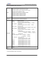
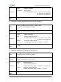
24、Enable/disable error detection in RX-1, RX-2, RX-3, RX-4: RX_ER_DETECT_EN ()
Name
void RX_ER_DETECT_EN(WDC_DEVICE_HANDLE hDev,
unsigned int RX_N,unsigned int en
)
Function
Enable/disable error detection in the Rx(RX-1/RX-2/RX-3/RX-4)
channel
hDev:
RX_N :
Parameter
en:
Return
Value
handle of the card
select the receive channel
possible assignment value: 1: select RX1 2: select RX2
3: select RX3 4: select RX4
enable/disable error detection
possible assignment value: 1: enable 2: disable
void
Orbita Control Engineering Co., Ltd.
- 56-
EMBC1000-PCI429E USER MANUAL
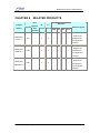
CHAPTER 7
Product
Number
EMBC1000PCI429EI-42
Rx
PRODUCT ORDERING INFO
Baud rate
Tx
Channel Channel
Software support
100K
50K
48K
12.5K
Windows 2000 or Windows XP
4
2
Orbita Control Engineering Co., Ltd.
√
√
√
√
based drivers and application
software
- 57-
EMBC1000-PCI429E USER MANUAL
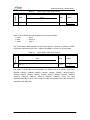
CHAPTER 8
RELATED PRODUCTS
Error
Product
Number
Interface
Rx
Injection
And
Baud rate
Tx
Software support
Channel Channel
100K 50K
Detection
48K
12.5K
Windows 2000 or
EMBC1000PCI429-42
Windows XP
PCI
4
2
√
√
√
√
based drivers
and application
software
Windows 2000 or
EMBC1000USB429-42
Windows XP
USB
4
2
√
√
√
√
based drivers
and application
software
Windows 2000 or
EMBC1000USB429EI-42
Windows XP
USB
√
4
2
√
√
√
√
based drivers
and application
software
Orbita Control Engineering Co., Ltd.
- 58-
EMBC1000-PCI429E USER MANUAL
Appendix A: ARINC429 Protocol Introduction
ARINC429 is an international standard for Digital Information Transfer System (DITS). It
is application-specific for commercial and transport aircraft. It ignores the complexities
of different manufacturers’ avionics system interfaces and supplies uniform plat form for
system communication.
Based on the requirements of ARINC Specification 429, digital information is
transmitted by wires in unidirectional data bus, differential coupling or twisted pairs. So
ARINC429 is serial communication. The ARINC429 standard supports High, Low, and
Null states.
ARINC data words are always 32 or 25 bits in length. Transmission of sequential words
is separated by at least four Null bits. Each ARINC word contains a parity bit, 8-bit label.
The label words are quite important in ARINC429 and identify the data type and the
parameters associated with it, such as latitude data, longitude data. The rest data bits of
the word are divided into different fields based on the label. For making communication
completely standardized and to avoid conflicts, all of the flight functions have been
given labels and data formats.
When a 32-bit ARINC word is transmitted, each word contains:
•
•
•
•
•
Parity
SSM
Data
SDI
Label
:
:
:
:
:
bit32
bit31~30,
bit29~11
bit10~9,
bit8~1
Sign Status Matrix
Source Destination Identifiers
The 32-bit ARINC Word typically use the format shown in Table A-1 which includes five
primary fields, namely P (parity), SSM, Data, SDI, and Label. Attention, ARINC
convention numbers the bits from 1 (LSB) to 32 (MSB), not from 0 to 31 as usually.
The order of 32-bit data word transmitted on ARINC bus is as follows (LSB first):
Label(8)- Label(7)- Label(6)- Label(5)- Label(4)- Label(3)- Label(2)- Label(1)- SDI(1)SDI(2)- Data(1)- Data(2)- Data(3)- Data(4)- Data(5)- Data(6)- Data(7)- Data(8)- Data(9)Data(10)- Data(11)- Data(12)- Data(13)- Data(14)- Data(15)- Data(16)- Data(17)Data(18)- Data(19)- SSM(1)- SSM(2)- Parity. The least significant bit of each byte,
except the label, is transmitted first, and the label is transmitted ahead of the data in
each case.
Orbita Control Engineering Co., Ltd.
- 59-
EMBC1000-PCI429E USER MANUAL
PARITY
Table A-1. 32-bit ARINC Data Word Format
32
DATA
SSM
31~30
SDI
29 ~ 11
10~9
LABEL
8~ 1
When a 25-bit ARINC word is transmitted, each word contains:
• Parity
• Data
• Label
:
:
:
bit25
bit24~9
bit8~1
The 25-bit ARINC Word typically use the format shown in Table A-2. Attention, ARINC
convention numbers the bits from 1 (LSB) to 25 (MSB), not from 0 to 25 as usually.
PARITY
Table A-2. 25-bit ARINC Data Word Format
25
DATA
24 ~ 9
SDI
10~9
LABEL
8~ 1
The order of 25-bit data word transmitted on ARINC bus is as follows (LSB first):
Label(8)- Label(7)- Label(6)- Label(5)- Label(4)- Label(3)- Label(2)- Label(1)-Data(1)
-Data(2) -Data(3) -Data(4) -Data(5) -Data(6) -Data(7) -Data(8) -Data(9) -Data(10)
-Data(11) -Data(12) -Data(13) -Data(14) -Data(15) -Data(16) –Parity. The least
significant bit(LSB) of each word except the label is transmitted first, and the label is
transmitted with MSB first.
Orbita Control Engineering Co., Ltd.
- 60-