1
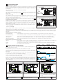
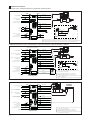
www.atos.com
Table G340-7/E
Digital position Z-ME-KZ controllers
Eurocard format, for electrohydraulic closed loop controls
Z-ME-KZ
MAIN FUNCTIONS AND FEATURES
USER INTERFACE
SUPPLY 24V
POSITION REFERENCE
ENT
ESC
UP
DWN
X1
X2
O1
O2
O3
O4
O5
O6
O7
A3
A4
A5
POSITION FEEDBACK
Position
control
Alternated
control
Real-time
fieldbus
Serial port
FORCE FEEDBACK
AUXILIARY INPUT
Internal
reference
DRIVER’S COMMAND
Enhanced
diagnostic
OUTPUTS
I1
I2
I3
I4
I5
I6
I7
I8
A1
A2
P/Q
RS232
INPUTS
FORCE REFERENCE
OK
MONITOR
PROFIBUS
Z-ME-KZ
AUXILIARY OUTPUT
Z-ME-KZ
Z-SW-PS
programming software
1
Z-SW-PS
MODEL CODE
-
Z-ME
KZ
-
PS
/
*
/
*
/
*
Electronic axis controller
in Eurocard format
Electrical Features:
• 4 digits front panel display to check and
change parameters as well as for diagnostics
• Front panel DB9 connector for serial programming interface
• Front panel test points for debug and
maintenance
• Eurocard format (DIN 41494 - Plug-in-units)
• CE mark according to EMC directive
Set code
Alternated position / force
(or position / pressure) control module
Series number
Serial communication interface for configuration
and monitoring function
2
SW
-PS
Optional fieldbus interfaces:
- = standard without fieldbus interface
BC = CANopen communication interface
BP = PROFIBUS DP communication interface
BLOCK DIAGRAM
DIGITAL CONTROLLER Z-ME-KZ
SETPOINT
GENERATOR
PROPORTIONAL VALVE
POSITION CONTROL
INT
FIELDBUS NETWORK
Software Features:
• Internal generation of motion cycle
• Setting of axis’s dynamic response (PID) to
optimize the application performances
• Software selectable range of electronic
reference analog inputs: voltage or current
• Enhanced diagnostics of the axis status
• Intuitive graphic interface
• In field firmware update through standard
serial communication
• Internal oscilloscope function
SERIAL PORT
Z-SW-PS
SOFTWARE
PID
EXT
FIELDBUS
FORCE CONTROL
M
I
N
PID
MONITOR
DIGITAL I/O
MACHINE
CENTRAL
UNIT
Digital axis controllers perform the position
closed loop of linear or rotative hydraulic
axes.
The controller receives a position feedback
from the axis transducer and it generates a
reference signal to the proportional valve
which regulates the hydraulic flow to the
actuator.
The position feedback interfaces are SSI,
incremental encoder, potentiometer or standard analog inputs (voltage or current)
software selectable.
A front panel serial port is always present for
configuration and monitoring of the controller.
The controller can be operated in real time
by external or internally generated reference
signal.
With external reference signal the actuator’s
motion cycle can be managed by either analog or fieldbus reference input.
With internally generated reference signal the
actuator’s motion cycle can be managed by
external or fieldbus on/off commands.
A pressure/force alternated control may be
set by software additionally to the position
control: a pressure/force transducer has to
be assembled into the actuator and connected to the controller; a second reference
pressure/force signal is required.
Several auxiliary digital inputs/outputs are
available and they can be used to synchronize other machine functions and to transmit
information on the controller state.
FORCE / PRESSURE FEEDBACK
POSITION FEEDBACK
HYDRAULIC ACTUATOR
Note: Block diagram example for alternated position/force control, with fieldbus interface.
G340
3
POSITION REFERENCE MODE
3.1 External reference generation
External reference generation
Z-ME-KZ controller regulates in closed loop the actuator position according to an external
reference position signal and to the position feedback from the actuator transducer. It
generates a reference signal for the proportional valve which regulates the hydraulic flow
to the actuator.
Analog (a) or Fieldbus (b) reference
Machine
central unit
ENT
ESC
Valve command
and monitor
position
I1
I2
I3
I4
I5
I6
I7
I8
A1
A2
The external reference signal can be software selected among:
Analog reference (a)
The controller receives in real time the reference signal from the machine electronic central
unit by means of the analog input (see section 10 ) limiting speed, acceleration and deceleration values.
t
X1
O1
O2
O3
O4
O5
O6
O7
A3
A4
A5
X2
PROFIBUS
RS232
M
UP
DWN
OK
Z-ME-KZ
Fieldbus reference (b)
The controller receives in real time the reference signal from the machine electronic central
unit by means of the digital fieldbus communication (BC and BP executions) limiting
speed, acceleration and deceleration values.
Internal reference generation
On-off (c) or Fieldbus (d) commands
For fieldbus communication details, please refer to the controller user manual (see section 12 ).
Machine
central unit
3.2 Internal reference generation
The internal reference signal is generated by a pre-programmed cycle; only start, stop and
switch-over commands are required from the machine electronic central unit by means of:
pos
I1
I2
I3
I4
I5
I6
I7
I8
A1
A2
O1
O2
O3
O4
O5
O6
O7
A3
A4
A5
X1
X2
PROFIBUS
RS232
M
UP
DWN
OK
Speed profile generated
- on-off commands (c)
ENT
ESC
Valve command
and monitor
Z-ME-KZ controller regulates in closed loop the actuator position according to an internally
generated reference position signal and to the position feedback from the actuator transducer. It generates a reference signal for the proportional valve which regulates the
hydraulic flow to the actuator.
Z-ME-KZ
switch-over points
- fieldbus commands (d)
Z
Atos PC software allows to design a customized sequence of motion phases adapted to the specific application requirements: a range of predefined
standard sequences are available in the Z-SW software.
Start/stop/switch-over commands and reference generation type can be set for each phase in order to realize an automatic cycle according to the application requests. Refer to the controller user manual for further details on the available selection of start/stop/switch-over commands and reference generation type.
Start/stop/switch-over commands examples
External digital input
on-off commands, on rear connector, are used to start/stop the cycle generation or to change the motion phase
External fieldbus input
on-off commands, by fieldbus communication, are used to start/stop the cycle generation or to change the motion phase
Switch by position
switch-over from actual to following motion phase occurs when the actual position reaches a programmed value
Switch by time
switch-over from actual to following motion phase occurs after a fixed time, starting from the actual phase activation
Switch by internal status
switch-over from internal status are used to start/stop the cycle generation or to change the motion phase
Internal reference generation types examples
Absolute
a target position reference signal is internally generated for each motion phase; maximum speed, acceleration and
deceleration can be set to obtain a smooth and precise position control
Relative
as ‘Absolute’ but the target position corresponds to the actuator position plus a fixed quote internally set by software
Hold
the controller holds the actual position
4
forward
force
movement
control
POSITION / PRESSURE OR FORCE CONTROL
backward force
movement
control
Alternated pressure or force control can be added to the actuator’s standard position control (see below functional schemes).
Remote transducers (pressure or force) have to be installed on the actuator.
Speed profile generated
The position/pressure (or position/force) controls are operated according to two separate
reference signals and a dedicated algorithm automatically selects which control is active
time by time.
The dynamics of the switching between the two controls can be regulated thanks to specific software setting, in order to avoid instability and vibrations.
t
Position control is active (see phase and at side) when the actuator actual pressure
or force is lower than the relevant reference signal.
reference value
actual value
force
Pressure or force control is active (see phase and at side) when the actuator actual
pressure or force, measured by remote transducers, grows up to the relevant reference
signal - the controller reduces the valve’s regulation in order to limit the actuator pressure
or force; if the pressure or force tends to decrease under its reference signal, the position
control returns active.
Alternated Position/Pressure Control
ENT
ESC
Alternated Position/Force Control - Load cell
O1
O2
O3
O4
O5
O6
O7
A3
A4
A5
I1
I2
I3
I4
I5
I6
I7
I8
A1
A2
X1
ENT
ESC
X1
DRIVER
RS232
PROFIBUS
X1
RS232
B
PROFIBUS
P
DRIVER
A
RS232
B
Z-ME-KZ
T
P
X2
DRIVER
A
Z-ME-KZ
PROFIBUS
P
T
A
B
P
T
Z-ME-KZ
T
T
P
one remote pressure transducer has to be
installed on the actuator’s port to be controlled
T valve’s spool transducer
O1
O2
O3
O4
O5
O6
O7
A3
A4
A5
I1
I2
I3
I4
I5
I6
I7
I8
A1
A2
X2
UP
DWN
OK
O1
O2
O3
O4
O5
O6
O7
A3
A4
A5
I1
I2
I3
I4
I5
I6
I7
I8
A1
A2
P
X2
M
ENT
ESC
UP
DWN
OK
Alternated Position/Force Control - Two pressure transducers
L
M
M
UP
DWN
OK
t
T
one load cell transducer has to be installed
between the actuator and the controlled load
M actuator’s position transducer
P
two remote pressure transducers have to be
installed on the actuator’s ports; the actuator
force is calculated by the pressure feedbacks
(Pa - Pb)
pressure transducer
L
load cell
APPLICATION EXAMPLES
5
Hydraulic steering wheel in marine applications
Position control
Position
ENT
ESC
UP
M
DWN
OK
O1
O2
O3
O4
O5
O6
O7
A3
A4
A5
I1
I2
I3
I4
I5
I6
I7
I8
A1
A2
X1
Rudder controls on motor yachts and sail boats requires smooth control
for precise and reliable operations.
Z-ME-KZ controllers perform the rudder position control system, ensuring
accurate and repetitive regulations for a comfortable ride, thanks to:
X2
t
PROFIBUS
RS232
Z-ME-KZ
- analog position reference mode for real time controls
- potentiometer position transducer for simple and compact solution
- position PID control parameters to optimize the system response
- complete diagnostic information for advanced system monitoring
DRIVER
A
B
P
T
T
Wind turbines
Position control
Position
ENT
ESC
M
DWN
OK
The pitch control of the rotor blades is required to maximize the energy production. Accurate positioning, decentralized intelligence as well as long service life and reliability are required.
UP
O1
O2
O3
O4
O5
O6
O7
A3
A4
A5
I1
I2
I3
I4
I5
I6
I7
I8
A1
A2
X1
X2
t
- SSI digital position transducer for high precision control
- complete remote system management with fieldbus interface
- position PID selection to adapt the position control to the different wind
conditions
PROFIBUS
RS232
Z-ME-KZ controllers perform high quality regulation of the blade pitch
simplifying the system architecture, thanks to:
Z-ME-KZ
DRIVER
A
B
P
T
T
Position control
ENT
ESC
Speed profile generated
Wood machinery
Hydraulic wood machines require configurable and repetitive motion
profiles, accurate position controls, and digital signals for synchronization
purpose.
UP
DWN
OK
O1
O2
O3
O4
O5
O6
O7
A3
A4
A5
I1
I2
I3
I4
I5
I6
I7
I8
A1
A2
X1
Z-ME-KZ controllers allow remote control, thanks to:
X2
P
t
PROFIBUS
RS232
Pressure
Z-ME-KZ
- internal reference generation with maximum speed and acceleration settings
- analog position transducer for simple and reliable solution
- pressure transducer for alternated pressure control
- fieldbus connection for remote parameterization, commands, and controller
state indication
M
DRIVER
A
B
P
T
T
t
Bending Machines
Position control
Speed profile generated
ENT
ESC
UP
DWN
OK
O1
O2
O3
O4
O5
O6
O7
A3
A4
A5
I1
I2
I3
I4
I5
I6
I7
I8
A1
A2
X1
M
X2
P
t
PROFIBUS
RS232
- internal reference generation to simplify the machine control cycle
- digital position sensor for high resolution measurement system
- two pressure transducers for alternated force control
- fieldbus interface for easy machine control integration
- auxiliary digital outputs for system status indication (target reached, force
control active)
Force
DRIVER
A
B
P
T
T
t
Die-casting machinery
Position control
Speed profile generated
ENT
ESC
Z-ME-KZ controller combine high level position regulation with accurate
force control to provide in a single device a complete and dedicated
solution, thanks to:
P
Z-ME-KZ
UP
Clamp movements in die-casting phases involve fast/slow motion cycle with
accurate and repetitive alternated position/force controls for the mould safety
functions.
DWN
OK
O1
O2
O3
O4
O5
O6
O7
A3
A4
A5
I1
I2
I3
I4
I5
I6
I7
I8
A1
A2
X1
M
Z-ME-KZ controllers, with alternated position/force control, simplify the
hydraulic + electronic system architecture, thanks to:
X2
P
RS232
Machine tools for cold-forming flat sheets require complete, automatic,
programmable and flexible machine control to produce sheet metal panels
from punched blank.
PROFIBUS
t
- internal reference generation for repetitive working cycles
- SSI digital position transducer for accurate axis control
- two pressure transducers for alternated force control
- auxiliary digital inputs/output to synchronize the machine functions
- fieldbus connection for machine remote control and advanced diagnostics
P
Z-ME-KZ
Force
DRIVER
T
A
B
P
T
T
t
G340
6
MAIN CHARACTERISTICS
Power supply (see 11.1)
Nominal: +24 VDC
Rectified and filtered: VRMS = 20 ÷ 32 VMAX (ripple max 10 % VPP)
Max power consumption
10 W
Position transducer
SSI, incremental encoder, potentiometer, analog
Input range :
voltage ±10 VDC
current 0 ÷ 20 mA
Output range :
voltage ±10 VDC @ max 10 mA
current 0 ÷ 20 mA @ max 500 W load resistance
Input range :
0 ÷ 5 VDC (OFF state), 16 ÷ 24 VDC (ON state), 5 ÷ 16 VDC (not accepted);
Input impedance: Ri > 10 kW
Digital Outputs (1)
Output range :
0 ÷ 24 VDC ( ON state > [power supply - 2 V] ; OFF state < 1 V ) @ max 30 mA
Enable input
Range : 0 ÷ 5 VDC (OFF state), 16 ÷ 24 VDC (ON state), 5 ÷ 16 VDC (not accepted); Input impedance: Ri > 10 kW
Fault output (1)
Output range : 0 ÷ 24 VDC ( no fault state > [power supply - 2 V] ; fault state < 1 V ) @ max 50 mA
Analog reference outputs
±10 VDC @ max 30 mA
Inceremental encoder power supply
+5 VDC @ max 100 mA
Alarms
Position transducer out of range, analog input out of range
Card format
Eurocard 100x160 mm (Plug-in unit DIN 41494)
Card rear connector
Male DIN EN 60603/G. Available frame snap connector type E-K-64M (see tech table G800) To be ordered separately
Operating temperature
0 ÷ +50 °C (storage -20 ÷ +70 °C)
Front panel dimensions
128,4 x 40 mm
Mass
Approx. 250 g
Electromagnetic compatibility (EMC)
According to Directive 2004/108/CE (Immunity: EN 50082-2; Emission: EN 50081-2)
Communication interface
Serial
Atos ASCII coding
CANopen
EN50325-4 + DS408
PROFIBUS
EN50170-2/IEC61158
Communication physical layer
not insulated
serial RS232
optical insulated
CAN ISO11898
optical insulated
RS485
Analog Inputs
Analog Outputs
Digital Inputs
input impedance:
input impedance:
Ri > 100 kW
Ri < 500 W
Note: (1) external negative voltage not allowed (e.g. due to inductive loads)
7 TRANSDUCER CHARACTERISTICS
7.1
Position transducers
The accuracy of the position control is strongly dependent to the selected position transducer. Four different transducer interfaces are available on the
controller, depending to the system requirements: potentiometer, analog signal, SSI, and encoder, see 7.3.
Transducers with digital interface (SSI and encoder) allow the user to get high resolution and accurate measures. Transducers with analog interface
(potentiometer and analog signal) grant simple and cost effective solutions.
7.2
Pressure/force transducers
The accuracy of the pressure/force controls is strongly dependent to the selected pressure/force transducers (see section 4 ). Alternated pressure/force
controls require to install pressure transducers or load cell to measure the actual pressure/force values.
Pressure transducers allow easy system integration and cost effective solution for both alternated position/pressure and position/force controls (see tech
table G465 for pressure transducers details). Load cell transducers allow the user to get high accuracy and precise regulations for alternated
position/force controls.
The characteristics of the remote pressure/force transducers must be always selected to match the application requirements and to obtain the best
performances: transducer nominal range should be at least 115%÷120% of the maximum regulated pressure/force.
7.3
Transducers characteristics & interfaces - following values are just for reference, for details please consult the transducer’s datasheet
Position
Input type
Pressure/Force
Potentiometer
Analog
SSI
Incremental Encoder
Analog
±10 VDC
+24 VDC
+5 VDC / +24 VDC
+5 VDC / +24 VDC
+24 VDC
±10V
0 ÷ 10V 4 ÷ 20 mA
Serial SSI binary/gray
TTL 5Vpp - 150 KHz
±10 VDC 4 ÷ 20 mA
0,5 m/s
1 m/s
2 m/s
2 m/s
-
Max Resolution
< 0.4 % FS
< 0.2 % FS
1 mm
1 mm (@ 0.15 m/s)
< 0.4 % FS
Linearity error (2)
± 0.1% FS
< ±0.03% FS
< ± 0.01 % FS
< ± 0.001 % FS
< ±0.25% FS
Repeatability (2)
± 0.05% FS
< ± 0.005% FS
< ± 0.001 % FS
< ± 0.001 % FS
< ±0.1% FS
Power supply (1)
Controller Interface
Max speed
Notes: (1) power supply provided by digital controller
(2) percentage of total stroke
8 FRONT PANEL DESCRIPTION
9 FRONT PANEL VIEW
8.1 Keyboard and display
On the Z-ME-KZ front panel are available 4 function keys (ESC, ENT, UP, DWN),
and a numeric display (4 digits plus sign) to allow the user to view and change
the controller’s parameters as well as to display diagnostic messages.
The following parameters can be accessed (viewed or changed) via corresponding menu structure:
- command and actual values
- analog input / output values
- digital input / output status
- position sensor indication
- force / pressure sensor indication
Parameter’s changes of the configuration, control gains, trigger conditions, internal cycle, fault monitoring are not allowed via front panel operations.
Function Keys
Display
ENT
ESC
UP
OK Led
OK
Active Led
Digital Input Led
Digital Output Led
Auxiliary Led
8.2 LED indication
The led indications are used to display the internal status (Active, OK) of the controller or the status of the digital IO of the Z-ME-KZ. There are 22 led divided in
four different types:
- internal controller’s status (Active - OK)
- digital input status (I1 ÷ I8)
- digital output status (O1 ÷ O7)
- software programmable led (A1 ÷ A5) for specific functions
DWN
O1
O2
O3
O4
O5
O6
O7
A3
A4
A5
I1
I2
I3
I4
I5
I6
I7
I8
A1
A2
X1
X2
Test Points
RS232 serial programming port
8.3 Test points
PROFIBUS
RS232
PROFIBUS-DP port (*)
The test points present on the controller front panel can be used to monitor the
actual position (X1) and the force / pressure (X2) value measured by the relevant
transducers. Both signals are referred to the analog ground (┴) pin. The two
signals are respectively connected to P_MONITOR+ (X1) and F_MONITOR+ (X2)
analog output present on the rear connector of the controller card. These signals
can be software set to show other signals available in the controller (see 11.8 and 11.9).
Z-ME-KZ
(*) only for BP option
8.4 Communication ports
On the front panel of the Z-ME-KZ is always present a serial RS232 port to program the controller by the Atos Z-SW software (see section 12 ). All the
functional parameters of digital controller, like internal reference generation, controller dynamics, IO configurations, can be easily set and optimized by
the user.
For BP or BC options a second communication port dedicated to the selected fieldbus connection is present on the controller. For BP option the
PROFIBUS-DP port is located on the front panel of the Z-ME-KZ controller. For BC option the CANopen connection is located on the rear connector of the
Z-ME-KZ controller.
Through the fieldbus communication only the real-time parameters may be exchanged:
- position, velocity and force / pressure reference
- position, velocity and force / pressure feedback
- controller commands and status
- diagnostic / error messages
For more information about the front panel settings and fieldbus communication, please refer to the controller user manual.
10 ELECTRONIC CONNECTIONS - 64 PIN REAR CONNECTOR
f
d b
z
pin
f
d
b
z
2
DO 7
(O)
DI 1
(I)
F_TR2 +
(I)
nc
4
SSI clock +
(D)
DI 2
(I)
F_TR2 -
(I)
nc
6
SSI clock -
(D)
DI 3
(I)
F_INPUT +
(I)
nc
8
SSI data + / Inc Ua1 (D)
DI 4
(I)
F_INPUT -
(I)
nc
10
SSI data - / Inc /Ua1 (D)
DI 5
(I)
P_INPUT +
(I)
nc
2
4
6
8
10
12
12
Inc Ua2
(D)
DI 6
(I)
P_INPUT -
(I)
nc
14
Inc /Ua2
(D)
DI 7
(I)
F_TR1 +
(I)
nc
16
Inc Ua0
(D)
DI 8
(I)
F_TR1 -
(I)
nc
18
Inc /Ua0
(D)
ENABLE
(I)
P_TR +
(I)
nc
20
Inc +5VDC
(O)
DO 1
(O)
P_TR -
(I)
GND
22
nc
FAULT
(O)
VALVE_MONITOR + (I)
DO 3
(O)
24
nc
nc
VALVE_MONITOR -
(I)
DO 4
(O)
26
nc
DO 2
P_MONITOR +
(O)
DO 5
(O)
28
CAN_GND
(F)
DO 6
(O)
30
CAN_L
(F)
32
CAN_H
(F)
14
16
18
20
22
24
26
(O)
28
nc
AGND
30
CONTROL_OUTPUT + (O)
VREF -10VDC
(O)
V+
(PS)
VREF +10VDC
(O)
V0
(PS)
32
rear view
F_MONITOR +
(O)
(I) Input - (O) Output - (D) Digital transducers - (PS) Power supply - (F) Fieldbus interface, only for BC option
G340
11
SIGNAL SPECIFICATIONS
Atos digital controllers are CE marked according to the applicable directives (e.g. Immunity/Emission EMC Directive).
Installation, wirings and start-up procedures must be performed according to the prescriptions shown in tech table F003 and in the user manuals included in the Z-SW programming software.
The electrical signals of the controller (e.g. monitor signals) must not be directly used to activate safety functions, like to switch-ON/OFF the machine’s
safety components, as prescribed by the European standards.
11.1 Power supply (V+ and V0)
The power supply must be appropriately stabilized or rectified and filtered: apply at least a 10000 mF/40 V capacitance to single phase rectifiers or a
4700 mF/40 V capacitance to three phase rectifiers.
The controller is protected against overloads by a internal safety fuse: 3,15 A fuse.
11.2 Position reference input signal (P_INPUT+, P_INPUT-)
The controller allows to regulate the axis position in closed loop according to an external voltage or current reference input signal (P_INPUT+ and
P_INPUT-), see 3.1. The analog input is a differential input type.
The input range and polarity are software selectable within the maximum range ±10 VDC for voltage or 0 ÷ 20 mA for current; default setting is 0 ÷ 10 VDC.
Controller with fieldbus interface (BC or BP) can be software set to receive reference value directly by the machine electronic control unit (fieldbus
master); in this case the analog reference input signal can be used for start-up and maintenance operations.
11.3 Pressure or force reference input signals (F_INPUT+, F_INPUT-)
For alternated position/force (or position/pressure) control the Z-ME-KZ receives a second analog voltage or current reference input signal
(F_INPUT+,F_INPUT-) dedicated to the force (or pressure) closed loop control (see section 4 ).The analog input is a differential input type.
The input range and polarity are software selectable within the maximum range ±10 VDC for voltage or 0 ÷ 20 mA for current; default setting is 0 ÷ 10 VDC.
Controller with fieldbus interface (BC or BP) can be software set to receive reference value directly by the machine electronic control unit (fieldbus
master); in this case the analog reference input signals can be used for start-up and maintenance operations.
11.4 Position transducer input signal
A position transducer must be always directly connected to the controller: digital SSI (SSI clock+, SSI clock-, SSI data+, SSIdata-), digital Encoder
(Inc Ua1, Inc /Ua1, Inc Ua2, Inc /Ua2,Inc Ua0, Inc /Ua0), potentiometer or a generic transducer with analog interface (P_TR+, P_TR-) can be used.
For transducers with analog interface the input range and polarity are software selectable within the maximum range ±10 VDC for voltage or 0 ÷ 20 mA for
current; default setting is 0 ÷ 10 VDC.
Refer to position transducer characteristics to select the transducer type that maches the specific application requirements (see 7.1).
11.5 Force / pressure transducer input signal (F_TR1+, F_TR1-, F_TR2+, F_TR2-)
Analog remote pressure transducers or load cell with maximum ±10 VDC signal range must be directly connected to the controller in case of alternated
postion/force (or position/pressure) control.
Refer to pressure/force transducer characteristics to select the transducer type that mach the specific application requirements (see 7.2).
The input range and polarity are software selectable within the maximum range ±10 VDC for voltage or 0 ÷ 20 mA for current; default setting is 0 ÷ 10 VDC.
11.6 Analog valve monitor input signal (VALVE_MONITOR+, VALVE_MONITOR-)
The controller allows to monitor the regulation of the proportional valve which operates the hydraulic flow to the actuator (VALVE_MON+,VALVE_MON-).
The analog input is a differential input type.
The input range and polarity are software selectable within the maximum range ±10 VDC for voltage or 0 ÷ 20 mA for current; default setting is 0 ÷ 10 VDC.
11.7 Control output signal (CONTROL_OUTPUT+)
The error signal processed by the control algorithms generates the control output signal (CONTROL_OUTPUT+) for the external driver of the proportional
valve which operates the hydraulic flow to the actuator.
The output range and polarity are software selectable within ±10 VDC (for voltage) or 0 ÷ 20 mA (for current) maximum range referred to the analog
ground (AGND); default setting is ±10 VDC.
11.8 Position monitor output signal (P_MONITOR+)
The controller generates an analog voltage output signal proportional to the actual axis position; the monitor output signal can be software set to show other
signals available in the controller (e.g. analog reference, fieldbus reference, position error, valve spool position).
The output polarity is software selectable within ±10 VDC maximum range referred to the analog ground (AGND); default setting is ±10 VDC.
The P_MONITOR+ signal is also present on the front panel at test point X1.
11.9 Pressure or force monitor output signal (F_MONITOR+)
For alternated position/force (or position/pressure) control, the Z-ME-KZ generates an analog voltage output signal proportional to the actual pressure or
force applied to the actuator end; the monitor output signals can be software set to show other signals available in the controller (e.g. analog reference, force
reference).
The output polarity is software selectable within ±10 VDC maximum range referred to the analog ground (AGND); default setting is ±10 VDC.
The F_MONITOR+ signal is also present on the front panel at test point X2.
11.10 Enable Input Signal (ENABLE)
To enable the controller, a 24VDC voltage has to be applied on pin d18 referred to pin b28.
When the Enable signal is set to zero the controller can be software set to perform one of the following actions:
- move forward or backward in open loop - default setting
- move forward and maintain in closed loop a predefined actuator’s position (hold position)
- maintain the actuator actual position in close loop control
- disable the controller functioning (control output set to zero)
11.11 Fault output signal (FAULT)
Fault output signal indicates fault conditions of the controller (alarm active, reference or transducer signal cable broken, max error exceeded, etc.).
Fault presence corresponds to 0 VDC, normal working corresponds to 24 VDC (pin d22 referred to pin b28).
11.12 Power supply signal for potentiometer position transducer (VREF -10VDC, VREF +10VDC)
Power supply for potentiometer position transducer may be generated from the controller card using the VREF -10VDC and VREF +10VDC signal @ max 30 mA.
11.13 Power supply for incremental encoder position transducer (Inc +5VDC, GND)
Power supply for incremental encoder position transducer may be generated from the controller card using the +5VDC @ max 100 mA.
11.14 Digital input signals (DI1 - DI8)
The 8 digital inputs can be used to trigger a command or to read a system state. For each input by the Z-SW software, it is possible to set the polarity and
to match a proper condition within the following:
- start/stop/switch-over command in case of internal reference generation (see 3.2)
- specific operative command for hydraulic axis mode (referencing mode, jog mode, automatic mode)
- jog command
- disable pressure / force alternated control
11.15 Digital output signals (DO1 - DO7)
The 7 digital outputs can be used to generate digital signals useful to the system synchronization and for monitoring purpose. The digital outputs can be
configured in polarity and all the channels can be independently programmed by the Z-SW software.
Typically the digital outputs are used to:
- set alarm condition related with the hydraulic axis working phase
- identify a particular working condition to synchronize other machine functionalities
- signal target position reached
- signal pressure / force control active
- signal tracking error
11.16 CANopen communication signals - only for BC option
For controllers with CANopen communication interface, the connections are located on the rear connector: pin f28 (CAN_GND), pin f30 (CAN_L) and pin
f32 (CAN_H).
12 PROGRAMMING TOOLS - see tech table GS500
Valve's functional parameters and configurations, can be easily set and optimized using Atos Z-SW programming software connected via serial communication
port to the digital controller. Z-SW software is available in different versions according to the controllers’s communication interface: PS (Serial) Z-SW-PS,
BC (CANopen) Z-SW-BC and BP (PROFIBUS DP) Z-SW-BP.
For fieldbus versions, Z-SW software permits valve's parameterization through serial communication port also if the controller is connected to the central machine unit via fieldbus.
Full programming software, to be ordered separately :
Z-SW-*
DVD first supply
= software has to be activated via web registration at www.download.atos.com ; 1 year service included
Upon web registration user receive via email the Activation Code (software license) and login data to access personal Atos Download Area.
The software remains active for 10 days from the installation date and then it stops until the user inputs the Activation Code.
Z-SW-*-N DVD next supplies = only for supplies after the first; service not included, web registration not allowed
Software has to be activated with Activation Code received upon first supply web registration
Atos Download Area: direct access to latest releases of Z-SW software, manuals, USB drivers and fieldbus configuration files at www.download.atos.com
USB Adapters, Cables and Terminators, can be ordered separately
13 MAIN SOFTWARE PARAMETER SETTINGS
For a detailed descriptions of the available settings, wirings and installation procedures, please refer to the user manuals included in the Z-SW-* DVD
programming software:
Z-MAN-ME-KZ - user manual for Z-ME-KZ
13.1 External reference and transducer parameters
Allow to configure the controller reference and transducer inputs, analog or digital, to match the specific application requirements:
- Scaling parameters
define the correspondence of these signals with the specific actuator stroke or force to be controlled
- Limit parameters
define maximum/minimum stroke and force to detect possible alarm conditions
- Homing parameters
define the startup procedure to initialize incremental transducer (e.g. encoder)
13.2 Position PID control dynamics parameters
Allow to optimize and adapt the position controller closed loop to the wide range of hydraulic system characteristics:
- PID (position)
each part of the position controller closed loop algorithm (proportional, fine positioning advanced integral, derivative, feed
forward, etc.) can be modified in order to match the application requirements.
13.3 Multiple pressure/force PID control dynamics parameters
Allow to optimize and adapt the pressure/force controller closed loop to the wide range of hydraulic system characteristics:
- PID (pressure/force)
each part of the pressure/force controller closed loop algorithm (proportional, integral, derivative, feed forward, etc) can be
modified in order to match the application requirements. Through Atos software or using dedicated digital inputs it is possible
to select up to four different pressure/force PID parameters setting, stored into the controller. Switching the active setting of
pressure/force PID during the machine cycle allows to optimize the system dynamic response in different hydraulic working
conditions (volume, flow, etc.).
13.4 Control output signal parameters
Allow to configure the controller command for the proportional valve which regulates the hydraulic flow to the actuator:
- Scaling parameters
define the correspondence of the command signal to the specific valve reference signal range
- Limit parameters
define maximum/minimum range to detect possible alarm conditions
13.5 Monitoring parameters
Allow to configure the controller monitoring function of the positioning error (difference between actual reference and feedback) and detects anomalous
conditions:
- Monitoring parameters maximum allowed errors can be set for both static and dynamic positioning phases, and dedicated waiting times can be set to
delay the activation of the alarm condition and relevant reaction (see 13.6)
13.6 Fault parameters
Allow to configure how the controller detect and react to alarm conditions:
- Diagnostics parameters define different conditions, threshold and delay time to detect alarm conditions
- Reaction parameters
define different actions to be performed in case of alarm presence (stop at actual or preprogrammed position, emergency
forward/backward, controller disabling, etc.)
13.7 Digital IO configuration
Allow to configure the controller’s digital inputs/outputs to trigger/generate signals from /for the external machine central unit:
- Polarity
define the signal active state
- Trigger condition
define the input state to run a predefined internal command (see 11.14)
- Output state
define the digital output based on the internal controller state (see 11.15)
13.8 Motion phases parameters
When the internal reference generation is active a pre-programmed cycle can be generated; start/stop/switch-over commands and reference generation
types parameters can be set to design a customized sequence of motion phases adapted to the specific application requirements (see 3.2).
G340
14 WIRING BLOCK EXAMPLES
14.1 Position control - external analog reference - potentiometer actuator transducer
(1)
Rear side connections
POWER SUPPLY
24VDC
ANALOG POSITION
REFERENCE
+
z30
d30
VALVE REF.
z32
b22
VALVE MONITOR +
+
b10
b24
VALVE MONITOR -
ENT
UP
OK
DWN
I1
I2
I3
I4
I5
I6
I7
I8
A1
A2
O1
O2
O3
O4
O5
O6
O7
A3
A4
A5
b32
VREF +10VDC
b30
VREF -10VDC
b18
P_TR+
(3)
DI 1
d2
DI 2
d4
b20
P_TR-
DI 3
d6
b28
AGND
b26
ANALOG POSITION
MONITOR
d22
DIGITAL FAULT
ON=24VDC; OFF=0VDC
(2)
b12
d18
DIGITAL ENABLE
ON=24VDC; OFF=0VDC
ESC
X1
X2
RS232
Z-ME-KZ
d20
DO 1
d26
DO 2
O7
A3
A4
A5
b18
P_TR+
b20
P_TR-
b28
AGND
(1) For the valve driver electrical connection please refer to the specific technical table
(2) For the potentiometer position transducer connection please refer to transducer datasheet
(3) For the analog position transducer connection please refer to transducer datasheet
Z-ME-KZ-PS
14.2 Alternated position/force control - external reference - SSI actuator transducer - 2 pressure transducers - CANopen
(1)
Rear side connections
POWER SUPPLY
24VDC
(2) ANALOG POSITION
+
ANALOG FORCE
REFERENCE
d30
VALVE REF.
b22
VALVE MONITOR +
b24
VALVE MONITOR -
b14
PRESSURE 1+
b16
PRESSURE 1-
b2
PRESSURE 2+
+
b10
+
b6
REFERENCE
(2)
z30
z32
ESC
ANALOG POSITION
MONITOR
ANALOG FORCE
MONITOR
OK
b8
DWN
I1
I2
I3
I4
I5
I6
I7
I8
A1
A2
O1
O2
O3
O4
O5
O6
O7
A3
A4
A5
(4)
b4
PRESSURE 2-
f4
SSI CLOCK+
f6
SSI CLOCK-
b16
f8
SSI DATA+
b28
b26
f10
SSI DATA-
d32
f32
CAN_H
f30
CAN_L
f28
CAN_GND
d22
DIGITAL FAULT
ON=24VDC; OFF=0VDC
UP
b12
d18
DIGITAL ENABLE
ON=24VDC; OFF=0VDC
ENT
X1
X2
RS232
Z-ME-KZ
b28
AGND
O7
A3
A4
A5
PRESSURE 1+
(5)
AGND
(3)
Real-time
fieldbus
CANopen
INTERFACE
Z-ME-KZ-PS/BC
b14
(1) For the valve driver electrical connection please refer to
the specific technical table
(2) Only for start-up and maintenance operations
(3) CANopen fieldbus interface on rear connector
(4) For the SSI position transducer connection please refer to
transducer datasheet
(5) Pressure transducer connection with current signal output
14.3 Alternated position/force control - internal reference generation - encoder actuator transducer - load cell - PROFIBUS-DP
(1)
Rear side connections
POWER SUPPLY
24VDC
(2) ANALOG POSITION
+
ANALOG FORCE
REFERENCE
DIGITAL ENABLE
ON=24VDC; OFF=0VDC
ANALOG POSITION
MONITOR
ANALOG FORCE
MONITOR
DIGITAL FAULT
ON=24VDC; OFF=0VDC
d30
VALVE REF.
z32
b22
VALVE MONITOR +
b24
VALVE MONITOR -
b14
FORCE 1+
b16
FORCE 1-
f8
INC UA1
f10
INC /UA1
f12
INC UA2
f14
INC /UA2
f16
INC UA0
f18
INC /UA0
+
b10
+
b6
REFERENCE
(2)
z30
ESC
ENT
UP
b12
OK
b8
d18
DWN
I1
I2
I3
I4
I5
I6
I7
I8
A1
A2
X1
X2
O1
O2
O3
O4
O5
O6
O7
A3
A4
A5
b26
d32
d22
b28
(3)
RS232
PROFIBUS
Z-ME-KZ
AGND
Z-ME-KZ-PS/BP
12/14
f20
INC +5VDC
z20
GND
EXTERNAL
ENCODER
(4)
(1) For the valve driver electrical connection please refer to
the specific technical table
(2) Only for start-up and maintenance operations
(3) PROFIBUS-DP fieldbus interface on front panel
(4) For the encoder position transducer connection please
refer to transducer datasheet