1
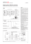
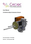
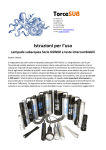
User Manual CO2-Sensor 10% / 30% / 100% Release 1.23 List of Releases Release Date 1.0 1.1 1.2 1.3 1.4 1.5 1.6 15.12.1997 01.06.1998 01.10.1998 07.02.2001 13.02.2001 21.08.2001 11.07.2005 Address: Telephone: Fax: Internet eMail: Datenmedia Author Remarks S.Otto S.Otto S.Otto S.Otto S.Otto S.Otto K.Techritz Basic software Minor modifications Revision of calibration New layout; change of address Transfer characteristic Adaptation to new software V1.23 st 1 English Version + minor modifications m·u·t GmbH Am Marienhof 2 D-22880 Wedel GERMANY +49 (0)4103 / 9308-0 +49 (0)4103 / 9308-99 http://www.mut-gmbh.de [email protected] User Manual CO2-LC V1.6e.doc Contents 1 TECHNICAL DATA............................................................................................................................ 5 2 IMPLEMENTATION........................................................................................................................... 6 2.1 ELECTRICAL CONNECTIONS ......................................................................................................... 6 2.2 GAS CONNECTIONS ..................................................................................................................... 7 3 CONNECTIONS................................................................................................................................. 8 3.1 OVERVIEW .................................................................................................................................. 8 3.2 TRANSFER CHARACTERISTICS .................................................................................................... 10 4 ADJUSTMENT OF SIGNAL OUTPUTS.......................................................................................... 11 4.1 CURRENT OUTPUT ..................................................................................................................... 11 4.2 VOLTAGE OUTLET ...................................................................................................................... 11 5 CALIBRATION................................................................................................................................. 12 5.1 REMARKS.................................................................................................................................. 12 5.2 SETTING OF ZERO-POINT ............................................................................................................ 13 5.3 SETTING OF CONCENTRATION ..................................................................................................... 14 5.3.1 Calibration-gas................................................................................................................... 14 5.3.2 Pressure-correction ........................................................................................................... 15 5.3.3 Calibration procedure ........................................................................................................ 16 User Manual CO2-LC V1.6e.doc 1 Technical Data Input voltage (Vcc) Input current (Icc) Cutout Value Signal-current loop interface Signal-voltage interface Display Accuracy Temperature range Compensation of temperature Gas Connections Hose Gas-flow Maximum Overpressure Measurement interval Step response [t90] Dimensions Weight Options User Manual CO2-LC V1.6e.doc 12V DC; opt. 24V DC ca. 150mA 200mA delayed 4mA..20mA (Resistive Load max. 100 Ohm at Vcc = 8V) optional, adjustable to 0..4V Full Scale ±2% Full Scale 10°C..40°C integrated Screw coupling Inner Diameter 3mm Outer Diameter 5mm Nylon/PVC/Neoprene, no Silicone-hose! ≤ 1 Litre/minute; 0.35 Litre/minute recommended 0.5bar (measurement at normal pressure) approx. 1s, every 23s correction cycles for 7s approx. 10s @ 350ml/min; depending on flow-through (100x160)mm2 max. construction height 50mm approx. 200g • Signal-voltage interface • Serial interfaces: RS232, RS422, RS485 Page 5 / 16 2 Implementation 2.1 Electrical Connections Kindly bear in mind to discharge possible electrostatic charges of your body at appropriate grounded devices (e.g. heater, grounded housing)! All electrical connections must be established before switching on the electrical supply! Avoid any mechanical forces of the cuvette (little aluminum block) on the circuit board! Touch the circuit board at its edges only! Connect the ground strap of the electrical supply with the connector GND (see also chapter Connections) and the anode with the connector Vcc. The used power supply must comply with the specifications referred to in the Technical Data. Connect the ground of the signal (separate terminal clamp but connected with supply ground) with the ground of the device to be fed. Voltage-fed plotting units (e.g. displays) must be connected with output 0..5V, current-fed devices with output +4..20mA. We recommend the connection with a shielded cable with a twisted pair (STP) grounded from both sides. The CO2-sensor is delivered calibrated with the values 4 and 20mA for the current interface and with concentration values of 0% and full scale {10% / 30% / 100%}. User Manual CO2-LC V1.6e.doc Page 6 / 16 2.2 Gas Connections Loosen the knurled nut of the hose connections on the top of the cuvette. Counter-turn the cuvette at the same time with the other hand. Connect the knurled nut to the hoses. Push the hoses as far as possible on the connector and tighten the nuts hand-screwed (counter-turned again). The connections for in- and output are arbitrary. The temperature of the gas should be identically to the ambient air temperature of the gas-sensor. The environment of the sensorcard should not be polluted with high CO2 concentrations. Avoid forces and momenta on the cuvette; while loosening and tightening of the connecting nut hold and counter-turn the cuvette with the other hand! Provide the input with a filter to avoid soiling of the cuvette! The maximum pressure may not be exceeded (see Technical Data) During measurements the gas must discharge freely. Blockages of the gas-outlet will lead to errors in measurement due to pressure increase Increased flow rates will lead to errors in measurement – amongst others due to pressure increase (see Technical Data) User Manual CO2-LC V1.6e.doc Page 7 / 16 3 Connections 3.1 Overview User Manual CO2-LC V1.6e.doc Page 8 / 16 Name Vcc GND Type Terminal clamp Terminal clamp Description of Function Voltage-supply (8-12V DC) Ground connector for electrical supply „4..20mA“ GND Terminal clamp Terminal clamp „0..4V“ JP1 Terminal clamp Pin header R42, „ZERO“ R44, „SPAN“ Potentiometer Potentiometer Current Loop output (positive Signal ) Ground connector interface current/voltage (negative Signal) Voltage outlet (positive Signal), optionally! • force output to 4 mA on current loop interface (Jumper 4mA - center), adjustment with R83 • force output to 20 mA on current loop interface (Jumper 20mA - center), adjustment with R87 • current loop interface provides current proportional actual gas concentration (e.g. put Jumper on X10, factory-preset) Calibration (0% CO2-adjustment) Calibration (full scale value; e.g. 100%) R83, „4mA-Adjust“ R87, „20mA-Adjust“ Potentiometer Potentiometer Calibration of current interface of 4mA (see also JP1) Calibration of current interface of 20mA (see also JP1) D91 D51 LED green LED red D52 D53 LED yellow (HI) LED yellow (LO) Electrical supply o.k. Disturbed measurement values e.g. by strong air draft or considerable change of temperature. Exceeding of maximum value (i.e. > 10%/30%/100%) Undershooting of minimum value (i.e. < 0%) R70, „V-Out-Adjust“ Potentiometer Adjustment of voltage output, optionally! User Manual CO2-LC V1.6e.doc Page 9 / 16 3.2 Transfer characteristics The outlet current (4-20mA) measured at terminal clamps „+4..20mA“ and „GND“ is directly proportional to the measured concentration of gas. Current Relative Gasconcentration 0% 50% of maximum value 100% of maximum value 4mA 12mA 20mA Example: 100%-CO2-Sensor 0% CO2 50% CO2 100% CO2 Example: 30%-CO2-Sensor 0% CO2 15% CO2 30% CO2 The maximum value may be abbreviated with „FS“ (Full Scale). Transfer Function y: Rel. Gas Concentration [%FS] 100 90 80 70 60 50 y = 6,25x - 25 40 30 20 10 0 0 2 4 6 8 10 12 14 16 18 20 x: Current Loop Interface [mA] User Manual CO2-LC V1.6e.doc Page 10 / 16 4 Adjustment of signal outputs 4.1 Current output The 4-20mA-current interface must be calibrated in following order: 1. Connect a current-measuring instrument/ampere meter or a current sink to the terminal clamp X3 (+4..20mA) and X4 (GND) 2. 4mA-Adjustment: The jumper must be fitted on the pin header JP1 connecting the inner and the outer pin „4mA“. Then adjust R83 (4mA-Adjust) until the measuring instrument shows 4.00 mA. 3. 20mA-Adjustment: The jumper must be position on the pin header JP1 connecting the inner and the outer pin „20mA“. Then adjust R87 (20mA-Adjust) until the measuring instrument shows 20.0mA. 4. Measuring position The jumper must be connected to the pin header X10 (presetting by factory). The current outlet now supplies the current proportionally to the measured gas-concentration, exceeding/undershooting of approx. 0.1mA is overflow resp. underflow range) 4.2 Voltage outlet The adjustment of the voltage signal is done via the R70 (V-Out-Adjust). The voltage outlet „0..4V“ can be adjusted for an indicating device/plotting unit (e.g. built-in digital voltmeter). The voltage outlet may only be loaded high-resistive. User Manual CO2-LC V1.6e.doc Page 11 / 16 5 Calibration 5.1 Remarks Kindly proceed the calibration following the following two chapters by all means. Calibration-tests like changing of the length of the cuvette, adjustment of the detector or adjustments of potentiometers that are not designated for purpose require a new calibration in our factory. A calibration must be proceeded in following order: 1. Calibration/test of the current interface on 4.00mA 2. Calibration/test of the current interface on 20.0mA 3. Calibration/test of the sensor on 0% gas 4. Calibration/test of the sensor on full scale gas concentration User Manual CO2-LC V1.6e.doc Page 12 / 16 5.2 Setting of zero-point Also for the calibration please bear in mind the data conc. maximum pressure and maximum gas flow mentioned in the Technical Data! Before proceeding a gas-calibration either the voltage or the current interface should be calibrated! Prior to a calibration the CO2-sensor should be operated for at least 30 minutes in stable room temperature. For the zero-point setting you should ideally use a 100% nitrogen gas (e.g. purity better 3.5 i.e. better 99.95%). Rinse the cuvette thoroughly with the calibration-gas and either adjust the gas-flow to minimum or interrupt the flow before setting the calibration values. (The gas flowing out of the gas-container cools down considerably during its expansion and therefore adulterates the measured value.) The current outlet 4-20mA shall now generate a current flow from 4mA towards GND. Please make sure that a resistive load (internal resistance typ. 100Ohm) is connected between the current outlet and the ground connector GND. Adjust the Potentiometers R42. (ZERO) to a current flow of > 4mA . Then reduce the current slowly to 4mA. Stop the procedure when reaching the value and the yellow LED D53 (LO) is lid. Further adjustments change the calibration parameters without visible changes of current. The circuit needs to stabilize after changes of settings, therefore please observe the value for approx. 20 seconds. User Manual CO2-LC V1.6e.doc Page 13 / 16 5.3 Setting of concentration 5.3.1 Calibration-gas In principle it is possible to proceed the calibration (after setting of zero-point) with a gas of any concentration. However, the calibration is the more accurate the higher the concentration of the second calibration-gas. Therefore we recommend a calibration with 100% CO2 for the 100%-version respectively 30% CO2 (ideally in N2) fort the 30%-version. Generally the desired current value is calculated as follows: I required = 4mA + 16mA ⋅ ConcCG Conc FS Symbol Irequired ConcCG ConcFS Description required output current at concentration CCG concentration of calibration gas (e.g. 30% CO2) full scale concentration of gas sensor (e.g. 100% CO2) Example: ConcCG ConcFS Irequired Dimension mA %CO2 %CO2 desired value for the calibration 30% 100% 8.8mA User Manual CO2-LC V1.6e.doc Page 14 / 16 5.3.2 Pressure-correction It needs to be considered that generally the declaration of the concentration of the calibration-gas (ConcCG) is based on normal pressure (1013.25 mbar) and standard temperature (298 K). Due to the integrated temperature-compensation the difference in pressure needs to be calculated. The gas temperature should be identical with the environment temperature. In case the calibration is done under circumstances different to the standard circumstances the value shown by the sensor-card needs to be calculated newly with following formula to calculate the needed concentration of the calibration-gas. Conc DV = ConcCG ⋅ P ⋅ 1013,25mbar Symbol ConcDV ConcCG P Dimension %CO2 %CO2 mbar Example: ConcCG P 30% 1000mbar ConcDV Description Displayed gas concentration concentration of calibration gas (e.g. 30% CO2) pressure of gas inside cuvette (i.e. typically ambient pressure) 29.6 % If you calibrate your sensor with a premixed gas of 30% CO2 with the gas exhausted to ambient pressure of 1000mbar the displayed gas concentration shall be 29.6% (instead of 30%) ! With a gas sensor of 30% full scale this means one obtains an output current of 19.8mA (instead of 20.0mA). User Manual CO2-LC V1.6e.doc Page 15 / 16 5.3.3 Calibration procedure The sensor board must be taken into operation half an hour prior calibration. Also for the calibration please bear in mind the data conc. maximum pressure and maximum gas flow mentioned in the Technical Data! Rinse the cuvette thoroughly with the calibration-gas and either adjust the gas-flow to minimum or interrupt the flow before setting the calibration values. (The gas flowing out of the gas-container cools down considerably during its expansion and therefore adulterates the measured value.) The current outlet shall now generate a current flow towards GND that conforms with the desired value calculated in the last two chapters. Adjust the desired value via the potentiometer R44 (SPAN). If the desired value is 20mA, you should do the adjustment from a lower value as 20mA represents the possible maximum current value. A higher adjustment would lead to wrong calibration. The circuit needs to stabilize after changes of settings, therefore please observe the value for approx. 20 seconds. User Manual CO2-LC V1.6e.doc Page 16 / 16