1
PA. Communications Ltd
Trinity Farm, 28A Dunton Road,
Stewkley
LEIGHTON BUZZARD
LU7 OHZ
U.K.
Tel: 01525 240945 Fax: 01525 240063
Caring for the Second Sense
P.A. COMMUNICATIONS
ANNOUNCER SYSTEM
Model ; RNAS Yeovilton - DATIS / PATSI
INSTALLATION and COMMISSIONING GUIDE
This document contains collected instructions for the equipment installed under
P A Communications Works Order 1896 at RNAS Yeovilton in order to effect the transition
of the DATIS service, and associated PATSI [also known as DIU], within the new tower.
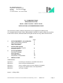
INDEX
page
1
DATIS EQUIPMENT: An Introduction
Datis Control Button Functions
Datis Block Diagram
Datis Connections
2
3
4
5
2
DATIS-PATSI System
Connecting PATSI to DATIS
Executive Control
6
7
3
PATSI EQUIPMENT
Patsi Block Diagram
Patsi Operation
Patsi Major States
Identification of Assemblies
8
8
9
10
13
4
INSTALLATION
14
APPENDICES
Appendix A
Connecting a Transmitter to a DA6U6 NATO DATIS
Appendix B
PATSI Composer EPROM DATIS
Appendix C
PATSI - EDDS Interface Protocol definitions {old EDDS}
Appendix D
A typical “Site INSPECTION & TEST Specification”
Appendix E
List of SEL-CODES
Issue A 18 May 2006
Datis/ Patsi RNAS Yeovilton New Tower Installation & Commissioning Issue A
1896ICA.doc
Page 1
1. EQUIPMENT: An Introduction
DATIS, DA6U6 is an ATIS recorder, providing an Air Terminal Information System that uses digital
recording and message playback techniques eliminating the wear and tear problems of mechanical
systems and thus increasing the reliability and availability of the service.
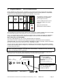
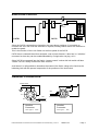
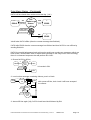
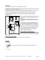
The DA6U6 is a desktop version
of DATIS which is operated at
the front panel controls,
It has a LEMO connector on the
front of the DM2 for the user's
headset.
Both Voice stores have
Alphanumeric Status Displays.
PLAY
PLAY
RECORD
RECORD
The message text is recorded by the operator and is retained in a VOICE STORE, when the message
is recorded and checked it may be put into service as being the current information.
The P. A. Communications "DATIS" provides a continuous flow of spoken information by replaying a
recorded message. The process of storage and replay of the text involves NO MOVING PARTS.
NATO Stock No. 51 RA 0160548
There are TWO IDENTICAL voice stores contained within the equipment.
One of the two stores is selected for providing the message for transmission and is termed the
"ONLINE STORE", the other store is available for preparation of further messages, (without disturbing
the online transmission) and is referred to as the "STANDBY STORE".
The press button switch panel is used both for preparing stored messages and to make the selection
of which store should be Online. Changeover, once initiated, occurs at the completion of the message
currently being transmitted.
A key operated switch on the DATIS front panel is used to select / deselect the set of press
buttons. The panel is marked "LOCKED" and "ACCESSED", it should be in the "LOCKED"
position for automatic PATSI operation.
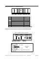
Both the Audio Output and the "off-air" input have telecommunications line interfaces, approved for
connection to B.T., in order that distant transmitter or receiver sites may be used.
240V
24V
A.C. input D.C. input
Rx
Tx
BT LINE CONN2
Alarm
A single remote transmitter
connects to a type B
(Post Office type)
jack socket at the rear of the
equipment.
This socket is marked “Tx”
The two multi pin "d type"
connectors, marked Alarm and
Conn2, are intended for
connection to PATSI
DA6U6 REAR PANEL
MOD LEVEL 3
Datis/ Patsi RNAS Yeovilton New Tower Installation & Commissioning Issue A
1896ICA.doc
Page 2
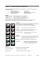
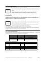
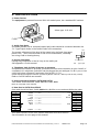
DATIS - Control Button functions.
There are twelve illuminated push button control switches in two columns, they can be
grouped by function.
1.
2.
3
4
STORE SELECTION
MONITOR SELECTION
MESSAGE CONTROL
DATIS CONTROL
Group 1
STORE 1 TO LINE
STORE 2 TO LINE
STORES OFF
Datis Output
Headset Signal
Message Recording and check
Executive Control
Selects message "1" for transmission.
Selects message "2" for transmission.
Disconnects both stores from Datis output.
The store selection controls the priority of the transmitted message.
Note that the three controls are interlocked with the lower button of group 4, the STORE CONTROL.
Datis operation requires that STORE CONTROL be held down while the selection is made.
Group 4
The "Store Control" button has a red indicator that lights while
the lock switch is in the "ACCESSED" position.
If the controls are "LOCKED" this led is extinguished.
4
1
Store1
TO LINE
INHIBIT
INHIBIT
Store2
TO LINE
DIRECT
STORES
OFF
STORE
CONTROL
Disconnects all output signals from the unit.
DIRECT
Allows transmission of messages direct from the
headset microphone. (Interlocked with Store Control).
STORE CONTROL
2
3
MONITOR
LINE
RECORD
MONITOR
S/B
REPLAY
S/B
MONITOR
Rx
LAMP
TEST
Group 3
RECORD
Interlock button to prevent accidental
operational changes.
Records headset microphone voice message to the
store not selected. (Note that if both stores are "off",
the same message goes to both stores.)
REPLAY S/B Replays the message on the standby channel.
LAMP TEST
Checks all button lamps when pressed.
The lamp test button illuminates all of the leds
except the "STORE CONTROL" led.
Group 2
MONITOR LINE
Outgoing Datis message to headset.
MONITOR STANDBY
Standby message to headset.
MONITOR R/X
Datis channel VHF receiver to headset.
Datis/ Patsi RNAS Yeovilton New Tower Installation & Commissioning Issue A
1896ICA.doc
Page 3
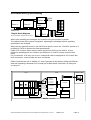
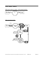
Introduction (continued)
AUDIO
Select
Store 1
Store 2
Out
DM2
DATIS
Switches
Simple block diagram
Shows STORES, Selection and Control.
DLC
Indicators
DLD
When used manually the messages are recorded using the operator's headset.
The selected store will continue to playback, repeating the message until the operating
requirements are changed.
When the key operated switch on the DATIS front panel is set to the "LOCKED" position it is
possible for PATSI to operate the Datis pressbuttons.
Cable 1573 connects these remote control signals from PATSI to the DATIS, in both
directions simulating both the switches and indicators of a DATIS remote control switch
panel.
For convenience, a 25 way “one to one” commercial cable is employed for 1573, fitted with
db25 connectors, one end male the other end female.
EDDS communicates via a “satellite PC” that is provided in the cabinet, taking the Ethernet
data and outputting commands via it’s serial port at 9600 baud, 8 bits data, no parity and
one stop bit.
CONTROL SCREEN
PATSI
DATIS
1010101011011
Status
Interface
to examine the
Datis' indicators
Desktop computer
Controller
Record
End Recd
Command
St 1 to line
St 2 to line
Stores Off
To be
Recorded
by DATIS
Interface
Word Store
Audio Output
PATSI
Composer
Schematic
Datis/ Patsi RNAS Yeovilton New Tower Installation & Commissioning Issue A
1896ICA.doc
Page 4
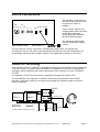
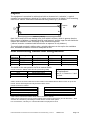
DATIS Connections.
240V
24V
A.C. input D.C. input
Rx
DA6U6 REAR PANEL
The majority of connectors at
the rear of the Datis are used
to connect to power or
facilities.
BT LINE CONN2
Alarm
Tx
There are two "type B" jack
sockets which are for the lines
to the radio equipment.
Audio signals are standard
600 ohm balanced pairs.
The telephone cable plugs
into the "answering machine
socket".
MOD LEVEL 3
The two multi pin "d type" connectors, marked Alarm and Conn2, are intended for
connection to PATSI, the audio voice signals from the DATIS to the ATIS transmitter are
continuously monitored and an alarm is given if the signal fails or drops to a low level.
Audio for recording
One of the two stores is selected for providing a message for transmission and is termed the
"ONLINE STORE", the other store is available for preparation of the new (or subsequent)
message, without disturbing the online transmission and is referred to as the "STANDBY
STORE".
The operator's voice is recorded when a message is prepared into either store.
The microphone of the operator's headset is used to pick up the audio, when PATSI
provides a real voice synthesis, the same route through the headset socket on the front
panel is employed.
AUDIO
Out
Select
Store 1
DATIS
Store 2
Operator Audio
DM2
DA6U6
Shows STORES and Operator audio
DLC
DLD
Conn2
Datis/ Patsi RNAS Yeovilton New Tower Installation & Commissioning Issue A
1896ICA.doc
Page 5
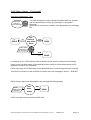
2. Connecting PATSI to DATIS.
The DATIS unit should be positioned on top of the PATSI unit, allowing the flying lead to be
plugged into the DATIS headset socket on the front panel.
265 mm
REVIEW
365 mm
Short interconnecting cables are fitted between the two units
The controls and indicators are via conn2, a db25 connector, this cable is fed to an indicator
booster board that is fitted inside DATIS.
The existing control switch panel and the PATSI Command board then both have access to
the Datis's "switches" and can also monitor the indicators.
The command board can be considered to be another "set of switches" that will operate the
DATIS.
PATSI
Block Diagram
Serial Port
from EDDS
Audio
Switching
Mic
Composer
Audio
Controller
Command
Board
to
Datis
The Audio Switching is arranged so that when DATIS is switched to "ACCESSED" a path
exists for the microphone signal to pass directly to the DATIS, in a "transparent manner",
the operator's headphone feed is "looped through" the LEMO sockets and remains
connected at all times.
Datis/ Patsi RNAS Yeovilton New Tower Installation & Commissioning Issue A
1896ICA.doc
Page 6
Executive control.
LOCKED
Datis +12V
ACCESSED
Command Board
Switches
PATSI
Indicators
DATIS
Since the DATIS commands are issued by the press button switches, it is possible to
common the "hot" side of all the switches on a panel, feeding twelve volts to the switches to
enable the panel.
This is the function of the Lock Switch on the front panel of the DATIS.
PATSI has a command board that emulates a set of press buttons, it also has it's "switches"
connected so that they can be enabled/disabled by a single wire carrying +12 V.
Since PATSI is connected into the Datis's "remote control" socket this lock switch will also
"isolate" PATSI's ability to effect the Datis controls.
At all times it is still possible to determine the status of the Datis, owing to the fact that the
indicating leds will still operate irrespective of the positions of the lock switch.
Headset Connectors.
HEADPHONE
1
MIC.
6 54
3
7
812
N.C.
MIC.
N.C.
Headset
Headset
Connector
Connector
Lemo Type 3
"RAF"
Lemo Type 2
Datis/ Patsi RNAS Yeovilton New Tower Installation & Commissioning Issue A
"RN"
1896ICA.doc
Page 7
3. PATSI Equipment.
Command
Board
REVIEW
Composer
Controller
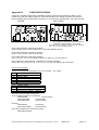
PATSI is constructed using plug-in eurocards housed in a 3U desk-top case.
It can operate from A.C. line or from auxiliary D.C. input power.
It is a multi-processor system using entirely solid state memory ( no disk drives ).
Two processors share the task :•
the controller which communicates with EDDS,
•
the second processor controls the speech composer which provides the
audio signal that is recorded into the Datis standby store.
A press button is provided on the front of PATSI that both selects the DATIS standby store
and puts it into replay, simulating a press of two Datis buttons.
The Audio Module has a LEMO socket to suit a standard RN headset, there is a flying lead
with a matching (size type 3B) LEMO plug for connection to the front of the DATIS.
Headset
Socket
Audio
Switching
Mic
Composer
Audio
to
Datis
Controller
to
Datis
Command
Board
Serial Port
to EDDS
PATSI
Block Diagram
Datis/ Patsi RNAS Yeovilton New Tower Installation & Commissioning Issue A
1896ICA.doc
Page 8
PATSI Operation
Each processor has a dedicated firmware contained in EPROM.
Composer
The composer provides the audio signal, it is a complete digital announcer on one
card, it is only necessary to change this one card in order to change the spoken
voice.
Each word or phrase ( known as a vocable ) has a unique two letter code, a
spoken message will consist of a quantity of vocables contained in a file.
The file is known as a word action list (WAL), it is stored in the composer's SRAM having been
transferred from the controller via the serial channel comms which is a serial link between the two
PATSI processors.
The firmware is called DVOX. It reacts to a small number of commands which are transmitted from the
controller via the serial channel comms. The control EPROM also contains the vocable tables that
allows the composer to recognise valid words and phrases.
Controller
The controller communicates with EDDS, it controls the DATIS with the command
board, it can both send commands to Datis and see that they have been acted
upon by examination of the led indicators.
The command board has a quantity of opto-isolators that "are lit" by the Datis
indicator booster board, mimicking the led indicators.
These opto-isolators are "read" by the controller to order to fetch Datis status.
The serial link to EDDS is fitted on this card. It is provided by a separate ACIA chip and RS232 level
converter to allow for most types of serial VDU and baud rate.
PATSI Commands.
All commands are via the serial port and are sent and received at 9600 baud.
[9600 N 8 1]
Controls to PATSI are two letter commands, starting with X.
Command
Xa
Xb
Xc
Xd
Xx
Control code set. (PATSI to EDDS)
Code
Name
Code I
Code II
Code III
Nack
ETB
ETX
X-Off
Ack
EM
BEL
not acknowledge
end of block
end of text
acknowledge
end of media
bell
Hex Value
$58,$61
$58,$62
$58,$63
$58,$64
$58,$78
Purpose
End of Phrase
End of File
Change Stores
Stores Offline
Hello (test \ handshake)
Hex Value
$15
$17
$03
$13
$06
$19
$07
Purpose
loading error
new message is online, running
good message in standby
error, please repeat file transfer
saying O.K to EDDS
Datis now offline
Datis Alarm is activated
Datis/ Patsi RNAS Yeovilton New Tower Installation & Commissioning Issue A
1896ICA.doc
Page 9
Patsi Major States
EDDS sends a check, Xx = hello - PATSI responds with Ack
from
EDDS
Xx
($58,$78)
CHECK
OK
Ack
to
($06)
EDDS
EDDS sends data to PATSI.
from
EDDS
Qty. of
2 letter
sel-codes
ending
with Xb
Bad
Receive
Data
Xoff ($13)
to
EDDS
Ack ($06)
Good
Bad
Datis Command
Record
code I
Nack ($15)
AUDIO
to Datis
upto 128S
Datis Command
Stop
Recording
Message
in Datis's
Standby
Store
ETX ($03)
Good
Datis/ Patsi RNAS Yeovilton New Tower Installation & Commissioning Issue A
1896ICA.doc
Page 10
Patsi Major States (Continued)
Datis store changeover. ( Xc )
Operator
Listens to
new message
upto 128S
Xc
from
EDDS
($58,$63)
The store changeover action should be initiated after the operator
has had opportunity to review (by listening to) the spoken
message.
Hence the Xc command is unlikely to be appended to the message
file.
Tell
Datis to
use other
Store
Ack
to
($06)
EDDS
ETB
to
($17)
EDDS
Datis plays
remainder of
old message
upto 128S
In response to Xc, PATSI will send Ack to indicate it has sent the command successfully.
Owing to the real time nature of the application there could be a time delay before DATIS
appears to act upon the command.
PATSI will check DATIS indicators until it determines that a store changeover has occurred.
Then PATSI will send a code to EDDS to indicate that "new message is online" = ETB=$17
DATIS has an alarm that will operate if the message fails during replay.
Datis
Audio Alarm
is activated
Test
Datis
Alarm
BEL
to
($07)
EDDS
PATSI can detect this and will send BEL=$07
Datis/ Patsi RNAS Yeovilton New Tower Installation & Commissioning Issue A
1896ICA.doc
Page 11
Patsi Major States (Continued)
DATIS will be closed down at the end of the day. ( Xd )
Tell
Datis to go
Stores
offline
Xd
from
EDDS
($58,$64)
Ack
to
($06)
EDDS
Datis plays
remainder of
current mess.
upto 128S
EM
to
($19)
EDDS
Xd will take DATIS offline (after the current message has finished).
PATSI tells EDDS that the current message has finished and that DATIS is now off-line by
sending EM=$19.
DATIS is normally left powered and at this point would now contain two messages which are
both off-line, should EDDS wish to delete these (perhaps in the early hours of the morning)
there is a command sequence that will perform this "trick".
1. Ensure DATIS is off-line,
Xd
from
EDDS
($58,$64)
Tell
Datis to go
Stores
offline
Ack
to
($06)
EDDS
Xd results in EM.
Datis plays
remainder of
current mess.
upto 128S
EM
to
($19)
EDDS
2. Load a short message containing silence, post it to Datis.
sel-codes
from
EDDS
for silence
ending
with Xb
Bad
Receive
Data
Xoff ($13)
to
EDDS
Ack ($06)
Good
Bad
Datis Command
Record
With stores off-line, both 1 and 2 will have accepted
the silence.
Nack ($15)
AUDIO
to Datis
2 Sec.
Datis Command
Stop
Recording
Message
in Datis's
Standby
Store
Good
ETX ($03)
3. Assert Off-line again (Xd), PATSI should send Ack followed by EM
Datis/ Patsi RNAS Yeovilton New Tower Installation & Commissioning Issue A
1896ICA.doc
Page 12
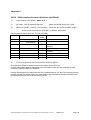
Identification of Assemblies.
REVIEW
LA
Unit
LA
LB
LC
LD
LE
LF
LG
LH
LJ
LB
LC LD
LE
LF LG
Description
Power supply unit (RAW DC)
Power supply unit (DC-DC)
Composer
Alternate Composer (New board)
blanking panel
Audio Module
Controller
Command Board
blanking panel
blanking panel
LH
LJ
Part No.
S32048
S33033
P12058
P12059
P19156
P12730
P19220
hp
12
12
4
8
12
4
8
12
12
84 hp
Plug in unit LC located in new tower at Yeovilton is new type P12059 S/no 1108
Fitted with four text sockets [4 of 6 as IC64, IC65, IC66 and IC67, IC67 contains the 2000 upgrade]
Rear of equipment showing connectors.
EDDS
Serial In/Out
D.C. Input A.C. Input
DATIS
ON
Control
Alarm
A +ve
C -ve
AUX D.C.
Input
Burndy Metalok Bantam, mating female line socket =
UTG6104SN
Datis/ Patsi RNAS Yeovilton New Tower Installation & Commissioning Issue A
1896ICA.doc
Page 13
4. INSTALLATION
1. Power Source
The equipment is powered from two 230V AC mains inputs, via a standard IEC sockets.
Mains fuse, inside IEC receptacle
20mm type 3.15 A M
FUSE
2. Audio from Datis
A suitable [twisted pair or screened twisted pair] cable should be connected between the
“Tx” Type B jack socket of the DA6U6 Datis to the transmitter.
Line
The master adjustment of the level of the output is by the Datis front panel
preset, VR1, set to suit level sent to line for ATIS transmitter, nominally
set to neg 13db on leaving factory.
3. Keying from Datis
Keying is by completion of the DC loop on the audio pair
See appendix A in this manual.
no connection
N.B.
Type B jack
4. Telephone Jack for DIAL-IN access to message
A separate line interface is provided, presented as a two wire connection on pins 2 and 5 of
a standard U.K. telephone cord which can be plugged into an analogue P.A.B.X. port, or into
a 431 jack being a Network Termination Point of the P.S.T.N.
(Public Switched Telephone Network operated by British Telecom, Mercury and the City of Hull).
Refer to DATIS DA6U6 user manual.
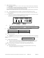
5. Interconnections between PATSI and DATIS
Two cables should be fitted, Cable 1573 and cable 1610.
Refer to next page of this manual.
6. Data feed to PATSI from EDDS
One cable should be fitted, Cable 1896 with a db25m on one end and db9f at the other.
db25m
1
2
3
4
5
6
7
8
20
Typical commercial cable wiring for db9 PC serial port
black ------- n.c.
n.c.
brown -----------------------------------------------red
red -----------------------------------------------brown
orange ------- n.c.
yellow ------- n.c.
green ------- n.c.
blue -----------------------------------------------blue
purple
------- n.c.
db9f
1
2
3
4
5
6
7
8
This cable connects to the more modern db9 rather than db25 version
See information on next page of this manual.
Datis/ Patsi RNAS Yeovilton New Tower Installation & Commissioning Issue A
1896ICA.doc
Page 14
Layout
The equipment is contained in cabinet that holds a nineteen inch “subracks”, a typical
example is a panel having a height of 5¼ inches, also known as 3U height. It has mounting
ears to suit “19inch” rack mount cabinets with fixing centres [f.c.] at 464 mm.
f.c. = 464 mm
133mm
3U
f.c.
57.25
mm
38mm
482mm (=19inch)
Both DATIS and PATSI are desktop units, their width is 475mm, which is greater than the
fixing centres of 464mm. A standard shelf is used inverted, and the cage nut rails inside the
cabinet are modified to take advantage of the full 482mm aperture.
( without inversion a standard shelf would offer an aperture of only 444mm.)
The total height required is 445mm plus a suitable clearance at the top for the ventilation
fans, estimated at 600mm to allow for adequate air flow.
Interconnecting cables and designations.
PATSI
Connector
db25f
db25m
db9m
IEC
Legend
EDDS
DATIS
DATIS
n/a
from EDDS
From Datis
From Datis alarm
AC Mains
Cable Number
Other end
1896
1573
1610
n/a
db25f
db9f
BS1362 plug top
The db25f on the rear panel of PATSI is marked EDDS.
PATSI connector “EDDS” db25 female (terminating 1896)
Pin 2
PATSI serial input
Pin 3
PATSI serial output
Pin 7
Only three pins out of the 25
are implemented.
Data in =2, Data out = 3 and
7 is Gnd.
SIGNAL GND
Cables number 1573 and 1610 are two link cables to the DA6U6 DATIS that is stood on top of the
PATSI, hence their length need only be about half a meter.
PATSI connectors “DATIS”
Alarm
db9 male (source 1610)
pins 5 and 9 only
Dry contacts
Facilities
db25 male (terminating 1573)
All pins to be connected
Bi-directional
Cable 1610 connects the DATIS Audio Alarm contacts to PATSI
Cable 1573 connects the remote control signals from PATSI to the DATIS, [in both directions – both
switches and indicators] simulating a DATIS remote control switch panel.
For convenience, a 25 way 1:1 commercial cable is employed for 1573.
Datis/ Patsi RNAS Yeovilton New Tower Installation & Commissioning Issue A
1896ICA.doc
Page 15
Appendix A
Connecting a Transmitter to a DA6U6 NATO DATIS
A single remote transmitter connects to a type B (Post Office type) Jack socket at the rear of
the equipment. The socket is marked “Tx”
[There are two type B jack sockets on the rear of the DA6U6, one marked “Tx”, the other is
marked “Rx” which is an input that accepts an audio pair from a monitor receiver.]
The Audio Output is designed to key the transmitter using the audio pair. When the
transmitter is required to send (TX ON) either RLA or RLB contacts provides a low
resistance loop.
LINE
FUSE
Txf 3
The audio output transformer has a split secondary
which has the A.C. circuit completed with a 2u2
capacitor.
The contacts of either RLA RLB are used to key
the transmitter, by placing a short across the 2u2
capacitor.
2u2
Txf 3
Line
2u2
Relay
Contacts
RLB
“short the 2u2”.
RLA
The transmitter line output is fully balanced and
has a fuse disconnection barrier using a 20 mm
type 160 mA quick blow (F) fuse in an enclosed
fuse holder on the DM2 plug in unit daughter board
There are two revisions of the Datis Module DM2,
both are interchangeable the older type uses
relays to select the store to line the later type
employs electronic switching.
Old Type DM2 plug in module (P11270).
The Datis Module has two relays for store selection,
(RLA for store one and RLB for store two). Hence there
are two sets of contacts in parallel either of which
New type DM2 plug in module
Has only one relay for keying, so only one contact to “short the 2u2”.
Connector.
Line
Both the audio and Tx keying is catered for using one balanced pair.
no connection
N.B.
Type B jack
Datis/ Patsi RNAS Yeovilton New Tower Installation & Commissioning Issue A
1896ICA.doc
Page 16
Appendix B
COMPOSER EPROMS
PATSI was originally shipped with a P12058 composer board that was replaced in 2000 in some
machines by one with a larger capacity, namely the P12059. The original composer card had four
plug-in EPROM, the control firmware ( DVOX 3 ) in U13 and three text EPROM - U64, U65 and U66.
P12058
New P12059
3U, 220mm x 100mm
IC13
IC14
3U, 220mm x 100mm
Control
EPROM
DVOX3
U13
SRAM
U14
Text Eproms
U64
U65
Audio
Level Adj.
Control
EPROM
1
IC64
IC65
IC66
IC67
IC67
1
6264
U66
IC55
R23
OUTPUT
LEVEL
IC20=4066
32
32
B12050
The composer located in the new tower at
Yeovilton is type P12059 S/no 1108
Fitted with four text sockets [4 of 6 as IC64, IC65, IC66 and
IC67, IC67 contains the 2000 upgrade]
U64 / IC64 contains the following vocables :Aa-Az, Ba-Bw, Ca-Cx, Da-Do, Ea-En Ew, JaJb, KaKb KdKeKf and Hb
U65 / IC65 contains the following vocables :Eo-Ez, Fa-Fz, Ga-Go, Ha-Hm, Ho-Hx, Ia-Il
U66 / IC66 contains the following vocables :Im-Iz, Jc-Jz, Kc, La-Lc, Le-Li, Ma-Md, Na-Nb, Pc, Qa-Qc, Cj, Kg, Kh and Hn
IC67 contains the 2000 upgrade, containing the following vocables :Bd, Bh, Bm, Gw, Gx, Gz, Ht, Hy, Jc, Ks, Kz, Lo, Lq-t, Mz, Nh, Np-Nw, Qj-m and Tb-To
Correct use of delays.
Delays should generally be placed in front of a vocable. e.g. CpEa
Co
Cp
Cq
Cr
32mS Pause
64mS Pause
96mS Pause
128mS Pause
Cs
Intake of breath
Cu
Cv
Cw
Cx
160mS Pause
192mS Pause
224mS Pause
Long pause + breath t = 608mS
The values of each delay is important.
As an audible example try the following.
KaJbEaAaXb
sounds strange
KaJbCoEaAaXb
sounds better
KaJbCpEaAaXb
sounds natural
whereas
KaJbKfAaXb
KaJbCoKfCoAaXb
sounds OK
sounds perfect
And using Ea again we have the best result
KaJbCpEaCoAaXb
Datis/ Patsi RNAS Yeovilton New Tower Installation & Commissioning Issue A
1896ICA.doc
Page 17
Appendix C
PATSI - EDDS Interface Protocol definitions {old EDDS}.
1)
Serial Comms Port Speed - 9600 N 8 1
2)
Xx=hello - PATSI responds with Ack
3)
Values for [codeI], [codeII], and [codeIII]. These are the PATSI to EDDS codes.
where Xx=$58 $78 and Ack = $06
So far we have mentioned Ack=$06 X-Off=$13 Nack=$15
PA Consulting Control code set. (PATSI to EDDS)
Code
Name
Hex
Value
Code I
Code II
Code III
Nack not
acknowledge
ETB end of block
$15
loading error
$17
ETX end of text
X-Off
$03
$13
new message is online,
running
good message in standby
error, please repeat file
transfer
saying O.K to EDDS
Datis now offline
Datis Alarm is activated
Ack acknowledge
EM end of media
BEL bell
4)
Purpose
$06
$19
$07
There is no protocol test in comms from EDDS to PATSI
The input from EDDS is stated in the PA consulting Group RFQ as:"These data stream shall be packaged into a message format and the meaning of each
character code are defined in Annex A"
Having discussed this by telephone both PA Communications Ltd. and PA consulting Group
confirm that PATSI should expect raw data without any preamble or header characters but
be simply followed by an Xb at the end of the file.
Datis/ Patsi RNAS Yeovilton New Tower Installation & Commissioning Issue A
1896ICA.doc
Page 18
Appendix D
P.A. COMMUNICATIONS Ltd.
ANNOUNCER SYSTEM.
SITE INSPECTION & TEST SPECIFICATION
Description:
PATSI to DATIS interface.
Document prep. date:
18th May 2006
Issue:
A
Customer Contract No.
Specification Number:
1896TA.DOC
Name of tester:
Works Order No. 1896
_______________
1.
SCOPE:
This specification covers all the hardware items of the above mentioned Works Order.
It requires that separate units of the order have previously been set-up and satisfactorily
performance tested where possible.
2.
METHOD To ensure all test and inspection items are covered, the tester must check the appropriate box for
each line as it is completed. [ tick box þ when done. ]
The PATSI should be connected to a fully functioning DATIS as detailed below
3.
SYSTEM ITEMS .
DA6U6 DATIS S/No 128 635
PATSI (DCU) S/No 100 588 496
Item
1
2
present
absent
Comments.
o
o
_______________
o
o
_______________
Equipment required to carry out testing
Headset with 10 pin LEMO connector ( RNAS standard).
PA Document : Installation & Commissioning guide 1896ICA.DOC
Suitable communications terminal capable of transmitting serial data at 9600 8N1
4.
EQUIPMENT FUNCTIONAL TESTS.
4.1
o Connect cables as diagram, including alarm cable 1610
Cable
Command cable
db25 to db25
Audio cable
REVIEW
Headset
Socket
4.2
o plug headset into mating connector on front of PATSI unit.
4.3
o
Position DATIS lock switch to ACCESSED.
o Press the LAMP TEST button and check that you have normal control of the DATIS
( the leds will light ).
Datis/ Patsi RNAS Yeovilton New Tower Installation & Commissioning Issue A
1896ICA.doc
Page 19
4.4
Make a manual test recording
o press the DATIS "Record" button. both voice stores will go into Record mode and the red RECORD
button lights.
o Having spoken the message into the microphone of the headset press "Replay S/B" button to terminate
the recording. The red record led goes off as we exit record.
o press the "Store One to Line" button to select STORE 1 TO LINE.
o Check that with MONITOR LINE selected, the recorded message is reproduced clearly in the headset.
4.5
o
4.6
o
Press the REVIEW button on the front panel of the PATSI, this should select and start replay from
the standby store.
4.7
o
Check the basic comms by connecting a communications terminal capable of transmitting serial data
at 9600 8N1 to the db25 port [marked EDDS] at the rear of PATSI.
Position DATIS lock switch to LOCKED. Check that the DATIS buttons do not react.
If necessary unplug cable 1896 that connects from EDDS.
EDDS
Serial In/Out
4.7.1
D.C. Input A.C. Input
DATIS
Alarm
Control
o Type in Xx at the communications terminal and ensure that there is an “Ack” reply.
Xx = hello - PATSI responds with Ack
4.8
ON
where Xx=$58 $78 and Ack = $06
The DATIS is controlled by PATSI when commanded via the serial link from EDDS.
There are three main functions.
RECORD SEQUENCE
send sel-codes to build a message
and end with command Xb
STORE CHANGE SEQUENCE
command Xc
STORES OFF SEQUENCE
command Xd
4.8.1.
RECORD SEQUENCE
Send a message to PATSI, observe that either (or both) store shows RECD and has corresponding
red leds lit
Store recording logic is a function of DATIS, the record sequence from PATSI emulates the record button being
pressed.
o
4.8.2
STORE CHANGE SEQUENCE
o
CsKaJbCpEaCoAxXaLaXb
Send an Xc to PATSI, observe that once the running message has finished the on-line store has
changed. ( the priority leds will change on the Datis as soon as the command has been sent ).
o
Send a second Xc to PATSI, observe that "the other store" will also change over.
PATSI observes the led indicators for both stores, so this test has to be performed for both stores.
4.8.3.
STORES OFF SEQUENCE
o
Send an Xd to PATSI, observe that both priority leds extinguish and that once the running
message has finished both stores stop replaying.
Datis/ Patsi RNAS Yeovilton New Tower Installation & Commissioning Issue A
1896ICA.doc
Page 20
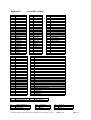
Appendix E
List of SEL-CODES
Aa
Ab
Ac
Ad
Ae
Af
Ag
Ah
Ai
Aj
Ak
Al
Am
An
Ao
Ap
Aq
Ar
As
At
Au
Av
Aw
Ax
Ay
Az
ALPHA
BRAVO
CHARLIE
DELTA
ECHO
FOXTROT
GOLF
HOTEL
INDIA
JULIET
KILO
LIMA
MIKE
NOVEMBER
OSCAR
PAPA
QUEBEQ
ROMEO
SIERRA
TANGO
UNIFORM
VICTOR
WHISKY
XRAY
YANKEE
ZUZU
Da
Db
Dc
Dd
De
Df
Dg
Dhi
Di
Dj
Dk
Dl
Dm
Dn
AMBER
BLACK
BLUE
GREEN
RED
YELLOW
WHITE
AMBER F.I.
BLACK F.I.
BLUE F.I.
GREEN F.I.
RED F.I.
YELLOW F.I.
WHITE F.I.
Xa
Xc
end of phrase
use new message
Fa
Fb
Fc
CUMULONIMBUS
STRATUS
CUMULUS
Ba
Bb
Bc
Bd
Be
Bf
Bg
Bh
Bi
Bj
Bk
Bl
Bm
Bn
Bo
Bp
Bq
Br
Bs
Bt
Bu
Bv
Bw
Zero
One
Two
Three
Four
Five
Six
Seven
Eight
Nine
Ten
Hundred
Thousand
Zero F.I.
One F.I.
Two F.I.
Three F.I.
Four F.I.
Five F.I.
Six F.I.
Seven F.I.
Eight F.I.
Nine F.I.
By
OH
Ea
Eb
Ec
Ed
Ee
Ef
Eg
Eh
Ei
Ej
Ek
El
Em
En
Eo
Ep
Eq
Er
Es
Et
Eu
Ev
Ew
Ex
Ey
Ez
Xb
Xd
Ca
Cb
Cc
Cd
Ce
Cf
Cg
Ch
Ci
Cj
Ck
Cl
Cm
Cn
Co
Cp
Cq
Cr
Cs
DECIMAL
DEGREES
DEGREES_C
FEET
METRES
YARDS
KNOTS
MILLIBARS
THOUSAND
KILOMETRES
PLUS
MINUS
10Km or more
GREATER THAN
32mS pause
64mS pause
96mS pause
128mS pause
Intake of breath
TERMINAL INFORMATION
CODE
TIME
DIVIDING RUNWAY
INSTRUMENT RUNWAY
DUTY RUNWAY
SURFACE WIND
COLOUR CODE
FORECAST COLOUR CODE
VISIBILITY
QFE
CLOUD
TEMPERATURE
DEW POINT
QNH
TRANSISTION POINT
FREEZING LEVEL
TWO DEGREE LEVEL
TWO THOUSAND FEET WIND
AIDS STATUS
AREA
DIVERSION AIRFIELD
DIVERSION
AIRFIELD
ELEVATION
RUNWAY
end of file
offline DATIS'
Ga
Gb
Gc
BEACON
DF
DRDF
Datis/ Patsi RNAS Yeovilton New Tower Installation & Commissioning Issue A
Ha
Hb
Hc
CLOUD
DRY
FINE
1896ICA.doc
Page 21
Fd
Fe
Ff
Fg
Fh
Fi
Fj
Fk
Fl
Fm
Fn
Fo
Fp
Fq
Fr
Fs
Ft
Fu
Fv
Fw
Fx
Fy
Fz
ONE-EIGHTH
TWO-EIGHTHS
THREE-EIGHTHS
FOUR-EIGHTHS
FIVE-EIGHTHS
SIX-EIGHTHS
SEVEN-EIGHTHS
EIGHT-EIGHTHS
DAMP
WATER
PATCHES
STANDING
FLOODED
LYING
CLOUDY
SHOWERS
MODERATE
SEVERE
SLEET
DRIZZLE
FREEZING
ALTO see Pa
NIMBO see Pb
Ia
Ib
Ic
Id
Ie
If
Ig
Ih
Ii
Ij
Ik
Il
Im
In
Io
Ip
Iq
Ir
Is
It
Iu
Iv
Iw
Ix
Iy
Iz
CRASH
EMERGENCY
BIRDS
SERVICABLE
UNSERVICABLE
ROTARY WING
FIXED WING
LEFT
RIGHT
UP
DOWN
FEW
SCATTERED
ON
OFF
BROKEN
OVERCAST
WET
DRY
WITHDRAWN
UNLIT
TEMPORARILY
WORK IN PROGRESS
VISUAL
RPS
WEATHER
La
Lb
Lc
Ld
Gd
Ge
Gf
Gg
Gh
Gi
Gj
Gk
Gl
Gm
Gn
Go
LIGHTING
RADAR
WATCHMAN
TACAN
VHF
UHF
BARRIER
PAR
SRA
SSR
VFR
IFR
Le
Lf
Lg
Lh
Li
ABOVE
BELOW
SIGNIFICANT
AT
FORECAST
Ja
Jb
Jc
Jd
Je
Jf
Jg
Jh
Ji
Jj
Jk
Jl
Jm
Jn
Jo
Jp
Jq
Jr
Js
Jt
Ju
Jv
Jw
Jx
Jy
Jz
CULDROSE
YEOVILTON
PORTLAND
BOSCOMBE
BOURNEMOUTH
BRISTOL
BRIZE NORTON
CARDIFF
CHANNEL
CHIVENOR
EXETER
FARNBOROUGH
LYNEHAM
MANSTON
PLYMOUTH
PREDANNACK
SCILLIES
SHAWBURY
SOUTHAMPTON
ST.ATHAN
ST.MAWGAN
UPPER HEYFORD
WADDINGTON
WESSEX
WITTERING
COTSWOLD
Hd
He
Hf
Hg
Hh
Hi
Hj
Hk
Hl
Hm
Hn
Ho
Hp
Hq
Hr
Hs
Ht
Hu
Hv
Hw
Hx
FOG
FROST
GALES
GUSTS
HAZE
HAIL
HILL FOG
ICY
LIGHTNING
MIST
Towering Cumulus
PARTLY CLOUDY
RAIN
SEA FOG
SNOW
STRONG WIND
LIGHT
HEAVY
DENSE
THUNDER
TURBULENCE
Ka
Kb
Kc
Kd
Ke
Kf
Kg
Kh
THIS IS
Weather time
REPORT
Weather Diversion
Crash Diversion
Terminal Information
Fixed Wing Diversion
Rotary Wing Diversion
Ma
Mb
Mc
VALLEY
MERRYFIELD
WYTON
Na
Nb
IN
OUT
Pa
Pb
Pc
ALTO
NIMBO
CUMULO
Qa
Qb
Qc
TIMES
DEPARTURES
RECOVERY
THIS IS A TEST MESSAGE
THE AUTOMATIC ATIS SERVICE IS TEMPORARILY SUSPENDED
NO SIGNIFICANT WEATHER
TEN KILOMETERS OR MORE see Cm
Datis/ Patsi RNAS Yeovilton New Tower Installation & Commissioning Issue A
1896ICA.doc
Page 22