1
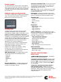
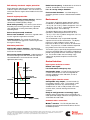
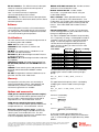
Digital generator set
1302 control kit
Description
Features
The 1302 control is a microprocessor-based generator
set monitoring, metering and control system.
12 and 24 VDC battery operation.
The control provides a simple operator interface to the
generator set, digital voltage regulation, digital engine
speed governing, start/stop control, 12 V/24 V battery
operation and generator set protective functions. The
1302 control also features support for full authority,
electronically-controlled engines. The integration of all
functions into a single control system provides enhanced
reliability and performance compared to conventional
generator set control systems.
The 1302 generator set control is designed for mounting
directly on the generator set and is suitable for use on a
wide range of generator sets in non-paralleling
applications. It is compatible with reconnectable
alternators up to 600 VAC line-to-line and can be
configured for any frequency, voltage and power
connection configuration from 120-600 VAC line-to-line,
and is compatible with shunt and PMG excitation
methods. It functions over a voltage range from 8 VDC
to 30 VDC.
The control offers a wide range of standard and optional
features so custom control configurations are not needed
to meet application specifications.
Power for the control is derived from the generator set
starting batteries.
Digital voltage regulation - Full wave rectified single
phase (line-to-line) sensing using shunt or PMG input
power.
Digital engine speed governing (optional) Provides isochronous frequency regulation.
Full authority engine support - Provides
communication and control between the engine control
module and the 1302 control.
Generator set monitoring - Monitors status of all
critical engine and alternator functions. Configurable for
single or three phase AC metering.
Engine starting - Includes relay drivers for starter, fuel
shut off (FSO), glow plug/spark ignition power and switch
B+ applications.
Generator set protection - Protects engine and
alternator.
Operator display panel - Provides easy-to-use
symbolic operator display of critical generator set
parameters and operating history.
Advanced serviceability - Utilizing InPower™, a PCbased software service tool.
Environmental protection - The control system is
designed for reliable operation in harsh environments.
The core control board is an encapsulated module that is
fully protected from the elements.
Configurable inputs and outputs - Four discrete
inputs and two dry contact relay outputs.
Certifications - Suitable for use on generator sets that
are designed, manufactured, tested and certified to
relevant UL, NFPA, ISO, IEC, Mil Std. and CE standards.
Warranty and service - Backed by a comprehensive
warranty and worldwide distributor service network.
©2007|Cummins Power Generation Inc.|All rights reserved|Specifications subject to change without notice|Cummins Power Generation
and Cummins are registered trademarks of Cummins Inc. InPower and “Our energy working for you.” are trademarks of Cummins Power
Generation. Other company, product, or service names may be trademarks or service marks of others.
S-1555 (1/08) Page 1 of 7
Control system
The standard control system includes a control board
with an external control switch and status indicator. The
control board includes all functions necessary to locally
or remotely start and stop, regulate voltage and protect
the generator set.
Optional engine speed governing
The control is available with an optional governor power
stage. This power stage amplifies control signals to
directly drive an engine fuel control valve.
Generator set hardware data - Access to the control
and software part number, generator set rating in KVA
and generator set model number is provided from the
optional display panel or InPower.
Data logs - Engine run time, controller on time, number
of runs and number of start attempts are available from
the optional display panel.
Fault history - Provides a record of the most recent
fault conditions with control hours time stamp. Up to 10
events are stored in the control non-volatile memory.
Alternator data
- Voltage (single or three phase line-to-line and line-toneutral)
- Current (3-phase)
- KVA
- Frequency
Engine data
- Starting battery voltage
- Engine speed
Display panel
The display panel may be either locally or remotely
mounted. The operator screens are made up of
internationally accepted symbols so translations are not
required. The display is composed of a backlit LCD
display with a series of 6 generator set status LED lamps.
The display is accompanied by six tactile-feel membrane
switches that are used by the operator to navigate
through control menus and to make control adjustments.
It is configurable for units of measurement and has
adjustable screen contrast and brightness.
The run/off/auto switch function is integrated into the
display panel; therefore, an external switch is not
required with the display panel option.
All data on the control can be viewed by scrolling
through screens with the navigation keys.
The control displays the current active fault and a timeordered history of the five previous faults.
LED indicating lamps - The display panel includes
LED indicating lamps for the following functions:
- Not in auto
- Shutdown
- Warning
- Remote start
- Auto
- Run
Operator adjustments - The optional display panel
includes provisions for many set up and adjustment
functions via raise/lower switches.
- Engine temperature
- Engine oil pressure
Service adjustments - The operator panel includes
provisions for adjustment and calibration of generator set
control functions. Adjustments are protected by a
password. Functions include:
- Engine speed governor adjustments
- 12 VDC/24 VDC battery operations
- Voltage regulation adjustments
- Cycle cranking
- Configurable fault set up
- Configurable output set up
- Meter calibration
- Display language and units of measurement
Other information
- Control not communicating
- Pop-up timers to indicate time remaining on time
delays in the system
Internal control functions
Engine control
12 VDC/24 VDC battery operations - Will operate
either on 12 VDC or 24 VDC batteries.
Isochronous governing (optional) - Controls engine
speed within +0.25% for any steady state load from no
load to full load. Frequency drift will not exceed +0.5%
for a 33 °C (60 °F) change in ambient temperature over
an 8 hour period.
Temperature dependent governing dynamics
(with governing option) - Modifies the engine
governing control parameters as a function of engine
temperature. Allows engine to be more responsive when
warm and more stable when operating at lower
temperature levels.
©2007|Cummins Power Generation Inc.|All rights reserved|Specifications subject to change without notice|Cummins Power Generation
and Cummins are registered trademarks of Cummins Inc. InPower and “Our energy working for you.” are trademarks of Cummins Power
Generation. Other company, product, or service names may be trademarks or service marks of others.
S-1555 (1/08) Page 1 of 7
Remote start mode - 1302 accepts a ground signal
from remote devices to automatically start the generator
set and immediately accelerate to rated speed and
voltage. The remote start signal will also wake up the
control from sleep mode. The control can incorporate a
time delay start and stop.
+1.5% for a 40 ºC (104 ºF) change in temperature in an 8
hour period. On engine starting, or sudden load
acceptance, voltage is controlled to a maximum of 5%
overshoot over nominal level.
Remote and local emergency stop - The control
accepts a ground signal from an external remote
emergency stop switch to cause the generator set to
immediately shut down. The generator set is prevented
from running or cranking with the switch engaged. The
control also accepts a ground signal from an external
local emergency stop switch. If in sleep mode, activation
of either emergency stop switch will wake up the control.
Torque-matched V/Hz overload control - The voltage rolloff set point and rate of decay (i.e., the slope of the V/Hz
curve) is adjustable in the control.
The automatic voltage regulator feature can be disabled
to allow the use of an external voltage regulator.
Sleep mode - The control is configured to include a
sleep mode. When the mode select switch is in the off
position, the control will revert to a low-powerconsumption mode until the run/off/auto control switch
or any button on the optional display panel is operated.
The control can be configured to go to sleep while in
auto mode in order to conserve the generator starting
batteries in applications that do not have battery
chargers.
Protective functions
Engine starting - The control system supports
automatic engine starting. Primary and backup start
disconnects are achieved by one of three methods;
magnetic pickup, battery charging alternator feedback,
or main alternator output frequency. The control also
supports programmable glow plug control. This feature
can be disabled when not required.
System protective functions
Cycle cranking - Configurable for number of starting
cycles (1 to 7) and duration of crank and rest periods.
Control includes starter protection algorithms to prevent
the operator from specifying a starting sequence that
might be damaging.
Time delay start and stop (cooldown) Configurable for time delay of 0-300 seconds prior to
starting after receiving a remote start signal and for time
delay of 0-600 seconds prior to shut down after signal to
stop in normal operation modes. Default for both time
delay periods is 0 seconds.
On operation of a protective function the display panel
will indicate fault description and time of occurrence.
The corresponding warning or shutdown LED will be
illuminated. The service manual and InPower service tool
provide service keys and procedures based on the fault
codes provided.
Configurable alarm and status inputs - 1302 will
accept up to four alarm or status inputs (configurable
contact closed to ground or open) to indicate customerspecified conditions. The control is programmable for
warning, shutdown or status indication and for labeling
the input.
Emergency stop - Annunciated whenever either
emergency stop signal is received from external switch.
Hydro mechanical full system engine
protection
Over speed shutdown - Default setting is 115% of
nominal.
When paired with a full authority, electronically controlled
engine, the 1302 can communicate with and control the
generator set.
Low lube oil pressure warning/shutdown - Level is
preset (configurable with InPower) to match the
capabilities of the engine used. Control includes time
delays to prevent nuisance shutdown signals.
Alternator control
Low coolant temperature warning - Indicates that
engine temperature may not be high enough for a 10second start or proper load acceptance.
The 1302 includes an integrated line-to-line sensing
voltage regulation system that is compatible with shunt
or PMG excitation systems. The voltage regulation
system is full wave rectified and has an SCR output for
good motor starting capability.
Major system features include:
Digital output voltage regulation - 1302 will regulate
output voltage to within +1.0% for any loads between no
load and full load. Voltage drift will not exceed
High engine temperature warning/shutdown Level is preset (configurable with InPower) to match the
capabilities of the engine used. Control includes time
delays to prevent nuisance shutdown signals.
Sensor failure indication - Logic is provided on the
base control to detect analog sensor or interconnecting
wiring failures.
©2007|Cummins Power Generation Inc.|All rights reserved|Specifications subject to change without notice|Cummins Power Generation
and Cummins are registered trademarks of Cummins Inc. InPower and “Our energy working for you.” are trademarks of Cummins Power
Generation. Other company, product, or service names may be trademarks or service marks of others.
S-1555 (1/08) Page 1 of 7
Full authority electronic engine protection
Engine protection and fault announcement is handled
inside the engine control module. The 1302 announces
active faults from the engine control module via the CAN
data link.
General engine protection
Low and high battery voltage warning - Indicates
status of battery charging system (failure) by
continuously monitoring battery voltage.
Weak battery warning - The control system will test
the battery each time the generator set is signaled to
start and indicate a warning if the battery indicates
impending failure.
Fail to start (overcrank) shutdown.
Fail to crank shutdown - Control has signaled starter
to crank engine but engine does not rotate.
Cranking lockout - The control will not allow the
starter to attempt to engage or to crank the engine when
the engine is rotating.
Alternator protection
High/low AC voltage shutdown - High default to
110% for 10 seconds, instantaneous 130%. Low default
to 85% for 10 seconds.
Overcurrent warning/shutdown - Implementation of
the thermal damage curve with instantaneous trip level
calculated based on current transformer ratio and
application power rating.
Under/over frequency - Under default to -6 Hz for 10
seconds. Over default +6 Hz for 10 seconds.
Loss of sensing voltage shutdown.
Field overload shutdown - uses field voltage to
shutdown generator set when a field overload condition
occurs.
Environment
The control is designed for proper operation without
recalibration in ambient temperatures from -40 ºC to
+70 ºC (-40 ºF to +158 ºF) and for storage from -55 ºC to
+80 ºC (-67 ºF to +176 ºF). Control will operate with
humidity up to 95%, non-condensing.
The optional display panel is designed for proper
operation in ambient temperatures from -20 ºC to
+70 ºC (-4 ºF to +158 ºF) and for storage from -30 ºC to
+80 ºC (-22 ºF to +176 ºF).
The control board is fully encapsulated to provide
superior resistance to dust and moisture. The display
panel has a single membrane surface, which is
impervious to effects of dust, moisture, oil and exhaust
fumes. This panel uses a sealed membrane to provide
long reliable service life in harsh environments.
The control system is specifically designed and tested for
resistance to RFI/EMI and to resist effects of vibration to
provide a long reliable life when mounted on a generator
set. The control includes transient voltage surge
suppression to provide compliance to referenced
standards.
Control interface
Input signals to the base control
Alternator
thermal
damage curve
Overcurrent
protection curve
10
Remote start signal
Local and remote emergency stop
Configurable inputs - Include (4) input signals from
customer discrete devices that are configurable for
warning, shutdown or status indication, as well as
message displayed.
Output signals from the control
Seconds
Configurable relay outputs - Control includes (2)
relay outputs rated at 2 amps. These outputs can be
configured to activate on any control warning or
shutdown fault, as well as ready-to-load, not-in-auto,
common alarm, common warning and common
shutdown.
1
0.03
1
10
Amps ( x rated)
Ready to load (generator set running) signal Operates when the generator set has reached 90% of
rated speed and voltage and latches until generator set is
switched to off or idle mode
Communications connections
®
Modbus interface - This RS-485 port allows the
control to communicate with external devices like PLC
on Modbus protocol.
©2007|Cummins Power Generation Inc.|All rights reserved|Specifications subject to change without notice|Cummins Power Generation
and Cummins are registered trademarks of Cummins Inc. InPower and “Our energy working for you.” are trademarks of Cummins Power
Generation. Other company, product, or service names may be trademarks or service marks of others.
S-1555 (1/08) Page 1 of 7
PC tool interface - This RS-485 communication port
allows the control to communicate with a personal
computer running InPower.
Note - An RS-485 converter is required for
communication between PC to control.
Networking - This RS-485 communication port allows
connection from the control to the other Cummins Power
Generation products
Software
InPower (beyond 5.5 version) is a PC-based software
service tool that is designed to directly communicate to
the 1302 generator set control components to facilitate
service and monitoring of these products.
Certifications
The 1301 control meets or exceeds the requirements of
the following codes and standards:
NFPA 110: For Level 1 or 2 systems.
ISO 8528-4: 1993 compliance, Controls and
Switchgear.
CE Mark: The control system is suitable for use on
generator sets to be CE Marked.
EN 50081-1, 2: Residential/Light Industrial Emissions
or Industrial Emissions.
EN 50082-1, 2: Residential/Light Industrial or Industrial
Susceptibility.
ISO 7637-2, level 2: DC Supply Surge Voltage Test.
Mil Std 202C, Method 101 and ASTM B117: Salt
Fog Test.
ISO9001: These control systems and generator sets are
designed and manufactured in ISO9001 certified
facilities.
UL 508: Recognized or Listed and suitable for use on
generator sets that are UL 2200 Listed.
RS 232 to RS 485 converter kit - Includes converter
and harness. Part number 0541-1199.
Remote annunciator kit - Includes remote
annunciator - see specification sheet S-1472, part
number 0300-5929-02.
Sales simulator - Allows operation of the control
system on a table top for sales demonstrations. Part
number 0541-1371 includes 1302 control (specifically for
use with simulator), display panel, mounting stand and
harness. Part number 0300-5461 includes universal
simulator.
Current transformers - Include 3 CTs for alternator
current metering/protection, part number 0541-1263-01
through -09, depending on ratio.
The 1302 is compatible with standard 5 amp secondary
CTs. The primary CT rating is sized to produce rated CT
secondary current of 2.5 amps at rated genset load (at
0.8 pf). To select the proper CT ratio you must first
calculate the lower and upper bound of the primary
rating. Once this is done, you select a CT turns ratio
within these bounds.
Part number
Turns ratio
Tap 1 - 2
(Primary / secondary)
Tap 1 – 3
P/N 0541-1263-01
P/N 0541-1263-02
P/N 0541-1263-03
P/N 0541-1263-04
P/N 0541-1263-05
P/N 0541-1263-06
P/N 0541-1263-07
P/N 0541-1263-08
P/N 0541-1263-09
50 / 5
75 / 5
100 / 5
150 / 5
200 / 5
250 / 5
375 / 5
400 / 5
500 / 5
100 / 5
150 / 5
200 / 5
300 / 5
400 / 5
500 / 5
750 / 5
800 / 5
1000 / 5
The lower bound of the primary ratio is calculated by
multiplying the maximum rated current by two (per
phase).
Min _ CT _ Ratio = 2 * Max _ Rated _ Current : 5
Warranty
eq. 3.1.1
All components and subsystems are covered by an
express limited 90 day warranty. Other optional and
extended factory warranties and local distributor
maintenance agreements are available.
The upper bound of the primary ratio is calculated by
multiplying the maximum rated current by five (per
phase).
Options and accessories
eq. 3.1.2
1302 genset control kit (non electronic engine) Includes a 1302 control module, operator interface, oil
pressure sender, coolant temperature sender and all
required harnesses. Part number 0541-1414-01.
Current is calculated by:
1302 genset control kit (electronic engine) Includes a 1302 control module, operator interface and
all required harnesses. Part number 0541-1414-02.
Electronic governing power stage - Includes an
actuator driver power stage compatible with the 1302
control system. Part number 0541-1231. This kit is
required for electronic governing. Care should be taken
to ensure compatibility with fuel actuator.
Max _ CT _ Ratio = 5 * Min _ Rated _ Current : 5
Current =
Power (VA)
3 *Voltage
or
Current =
Power (W )
3 * Power _ Factor *Voltage
In non-reconnectable genset applications the
Max_Rated_Current and Min_Rated_Current will be the
same. In reconnectable genset applications they will be
different.
©2007|Cummins Power Generation Inc.|All rights reserved|Specifications subject to change without notice|Cummins Power Generation
and Cummins are registered trademarks of Cummins Inc. InPower and “Our energy working for you.” are trademarks of Cummins Power
Generation. Other company, product, or service names may be trademarks or service marks of others.
S-1555 (1/08) Page 1 of 7
Example of CT sizing (non-reconnectable):
A 250 kVA rated genset application at 240 V producing
rated output current of 602 amps/phase. This would yield
a Min_CT_Ratio of 1204:5 and a Max_CT_Ratio of 3010:5.
Any CT with a ratio between these would be sufficient for
this application.
Example of CT sizing (reconnectable):
A reconnectable generator capable of 208-240/416-480 V
outputs with a 125 kVA 3 phase only rating.
We first need to find the current in each phase for each
output voltage. This is done using the following formula:
eq. 3.1.3
Using this equation above, the current in each phase is
computed and shown below.
Voltage (V)
Output current (A)
208
240
416
480
346.376
300.192
173.188
150.096
For the 208-240 voltage configuration:
Max _ CT _ Ratio = 5 * 300.192 = 1500.96
Min _ CT _ Ratio = 2 * 346.376 = 692.752
For the 416-480 voltage configuration:
Max _ CT _ Ratio = 5 * 150.096 = 754.8
Min _ CT _ Ratio = 2 * 173.188 = 346.376
For three tap CTs it would be advisable to choose a CT
with a 1500:5 ratio. For the 208-240 voltage
st
rd
configuration connect the CT leads to the 1 and 3 CT
connections, leaving the center tap un-connected. For
the 416-480 voltage configuration it would be advisable
to use the same 1500:5 ratio CT, but this time connect
st
nd
the CT leads to the 1 and 2 (center-tap) connections
on the CT. With this configuration one CT could be used
for all voltage configurations.
The next step is to use equations 3.1.1 and 3.1.2 to find
the lower and upper bound for the CT ratios for each
voltage configuration.
Mechanical drawings
224 (8.82)
33.5 (1.32)
100 (3.94)
141 (5.56)
GOVERNOR POWER
STAGE
75 (2.95)
111 (4.38)
BASIC CONTROL BOARD
149 (5.88)
Seconds
38 (1.50)
OPERATOR PANEL
Dimensions: mm (inches)
65 (2.56)
©2007|Cummins Power Generation Inc.|All rights reserved|Specifications subject to change without notice|Cummins Power Generation
and Cummins are registered trademarks of Cummins Inc. InPower and “Our energy working for you.” are trademarks of Cummins Power
Generation. Other company, product, or service names may be trademarks or service marks of others.
S-1555 (1/08) Page 1 of 7
Electrical interconnections
See your distributor for more information
Cummins Power Generation
Americas
rd
1400 73 Avenue N.E.
Minneapolis, MN 55432 USA
Phone: 763 574 5000
Fax: 763 574 5298
Europe, CIS, Middle East and Africa
Manston Park Columbus Ave.
Manston Ramsgate
Kent CT 12 5BF United Kingdom
Phone 44 1843 255000
Fax 44 1843 255902
Asia Pacific
10 Toh Guan Road #07-01
TT International Tradepark
Singapore 608838
Phone 65 6417 2388
Fax 65 6417 2399
Warning: Back feed to a utility system can cause electrocution and/or property damage. Do not connect to any building electrical except
through an approved device or after building main breaker is open.
©2007|Cummins Power Generation Inc.|All rights reserved|Specifications subject to change without notice|Cummins Power Generation
and Cummins are registered trademarks of Cummins Inc. InPower and “Our energy working for you.” are trademarks of Cummins Power
Generation. Other company, product, or service names may be trademarks or service marks of others.
S-1555 (1/08) Page 1 of 7