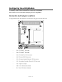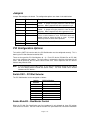
1
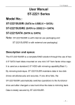
CMT7118HR User's Manual
High-Speed CompactFlash Controller with External IDE
BDM-610020040
Rev. A
ISO9001 and AS9100 Certified
CMT7118HR User's Manual
RTD EMBEDDED TECHNOLOGIES, INC.
103 Innovation Blvd
State College, PA 16803-0906
Phone: +1-814-234-8087
FAX: +1-814-234-5218
E-mail
[email protected]
[email protected]
Web Site
http://www.rtd.com
Page 2 of 13
Manual Revision History
Rev A
Initial Release
Published by:
RTD Embedded Technologies, Inc.
103 Innovation Boulevard
State College, PA 16803
Copyright 2005 by RTD Embedded Technologies, Inc.
All rights reserved.
The RTD Embedded Technologies Logo is a registered trademark of RTD Embedded
Technologies. dspModule, cpuModule, and utilityModule are trademarks of RTD Embedded
Technologies.
PC/104, PC/104-Plus, and PCI-104 are registered trademark of PC/104
Consortium.
Page 3 of 13
Table of Contents
Introduction ...................................................................................................................................... 5
Product Overview......................................................................................................................... 5
Board Features ............................................................................................................................ 5
Recommended Cables ................................................................................................................ 5
Physical Attributes ....................................................................................................................... 5
Getting Technical Support ........................................................................................................... 5
Configuring the utilityModule ........................................................................................................... 6
Connector and Jumper Locations ................................................................................................ 6
Connecting CompactFlash Drives ............................................................................................... 7
Connecting External Drives ......................................................................................................... 7
External LED Connectors JP2 and JP5 ....................................................................................... 7
Jumpers ....................................................................................................................................... 8
PCI Configuration Options ........................................................................................................... 8
Switch SW1 – PCI Slot Selector............................................................................................... 8
Solder Blob B3 – Bus Master Control ...................................................................................... 8
Board Installation ........................................................................................................................... 10
Installing the Hardware .............................................................................................................. 10
Static Precautions .................................................................................................................. 10
Steps for Installing.................................................................................................................. 10
Software Installation ...................................................................................................................... 11
DOS and Booting ....................................................................................................................... 11
Windows Support ....................................................................................................................... 11
Performing a Fresh Install of Windows 2000/XP or Windows NT 4.0.................................... 11
Linux........................................................................................................................................... 12
Other Operating Systems .......................................................................................................... 12
Limited Warranty............................................................................................................................ 13
Page 4 of 13
Introduction
Product Overview
The CMT7118HR is a high-speed, PC/104-Plus EIDE controller. It includes two CompactFlash
sockets, as well as an external EIDE connector. It is compatible with most operating systems,
including Windows, Linux, and DOS.
Board Features
o
o
o
o
o
o
Dual-channel PCI IDE Interface
Supports up to 4 EIDE Drives in a PC/104-Plus system
Two CompactFlash sockets on the primary channel
Two external drives on the secondary channel (0.1” connector)
CompactFlash sockets support +3.3V and +5V devices
Interface decoded from PC/104-Plus bus
Transfer rates up to UltraDMA133
Drive activity LEDs with external connections
Recommended Cables
•
40-conductor or 80-conductor EIDE cable which can be used to connect an external
drive (hard drive or CD-ROM drive) to the CMT7118.
Physical Attributes
o
o
o
o
o
Size: 3.6”L x 3.8”W x 0.6”H (90mm L x 96mm W x 15mm H)
Weight: 0.16 lbs (0.07 Kg)
o
o
Operating Temperature:
-40 C to +85 C
o
o
Storage Temperature:
-55 C to +125 C
Controller Power Requirements:
Typical:
1.75 W @ +5 VDC
Getting Technical Support
For help with this product, or any other product made by RTD, you can contact RTD Embedded
Technologies via the following methods:
Phone: +1-814-234-8087
E-Mail: [email protected]
Be sure to check the RTD web site (http://www.rtd.com) frequently for product updates, including
newer versions of the board manual and application software.
Page 5 of 13
Configuring the utilityModule
The following sections contain information on configuring the utilityModule.
Please read this entire section before attempting to use the utilityModule.
Connector and Jumper Locations
The figure below shows the location of the connectors and jumpers on the CMT7118.
o
CN1 – PC/104 XT Connector
o
CN2 – PC/104 AT Connector
o
CN4 – PC/104-Plus PCI Connector
o
CN7 – External EIDE Connector
o
JP2 – Primary Controller External LED Connector
o
JP5 – Secondary Controller External LED Connector
o
JP6 – Options Jumpers
o
SW1 – PCI Slot Selection Switch
o
B6 – Three PCI Master Selection
Page 6 of 13
Connecting CompactFlash Drives
The two CompactFlash sockets on the CMT7118 are attached to the primary IDE channel.
CompactFlash drives are installed by simply inserting them into the top and/or bottom sockets.
The top socket features an ejector. To remove the CompactFlash drive, press the ejector button
and slide the drive out of the socket. The bottom drive can be removed by pulling it out of the
socket.
Retention bars are available for both the top and bottom socket. The retention bars mount to the
PC board with screws, and prevent the CompactFlash drive from vibrating out or accidental
removal. Please contact RTD Embedded Technologies for more information.
The CompactFlash sockets operate in True-IDE mode. This means that they appear to the
operating system as a standard hard drive. However, this also means that they cannot be
inserted or removed while the system is operating.
Note:
Never install or remove any drive from the CMT7118 while power is applied to the
system. The CompactFlash sockets are not hot-swappable.
Connecting External Drives
The External Drive connector (CN7) on the CMT7118 is attached to the secondary IDE channel.
It allows two additional EIDE devices to be attached. They can be either additional hard drives,
or CD-ROM drives. If more than one drive is connected, one of the drives must be configured as
a master, and one as a slave.
There are two types of cables that are used for EIDE drives: a 40 conductor cable, and an 80
conductor cable. The 80 conductor cable adds a ground wire between each signal, and uses the
standard 40 pin connectors. A 40 conductor cable can be used for speeds up to UDMA Mode 2
(Ultra ATA/33). An 80 conductor cable is required for higher speeds. The BIOS or operating
system detects the type of cable that is attached, and selects an appropriate speed. The onboard CompactFlash sockets are configured in 80 conductor mode.
External LED Connectors JP2 and JP5
Two 2-pin connectors are provided for connecting an external drive activity LED. Current limiting
resistors are included on the CMT7118. The value of the resistors is 150 Ohm, with a 5V supply.
That provides a forward current of 20mA for an LED with a forward voltage of 2V. The connector
pin descriptions are shown below.
Pin
1
2
Description
LED Anode
LED Cathode
Page 7 of 13
Jumpers
Jumper JP6 configures the board. The configuration options are shown in the table below.
Label
Pin Numbers
Description
TOP 3V
1-2 (default)
TOP 5V
3-4
Selects 3.3V or 5V to power the top CompactFlash
socket. A jumper must be present in one of these
positions. Most CompactFlash drives operate at 3.3V.
BOT 3V
5-6 (default)
BOT 5V
7-8
Selects 3.3V or 5V to power the bottom CompactFlash
socket. A jumper must be present in one of these
positions. Most CompactFlash drives operate at 3.3V.
TOP MAS
9-10 (default)
BOT MAS
11-12
TOP MAS selects the top CompactFlash socket as
master, and the bottom as slave. BOT MAS selects the
bottom socket at master and top as slave. A jumper
must be present in one of these positions.
BA5 EN
13-14
Reserved. Jumper 13-15, or none.
RAID EN
15-16
PCI Configuration Options
To install the CMT7118 into the stack, the PCI Slot Number must be configured correctly. This is
done by the PCI Slot Selector located at SW1.
There are four possible PCI Slot Numbers (0 – 3). Each PCI device (PC/104-Plus or PCI-104)
must a use a different slot number. The slot number is related to the position of the board in the
stack. Slot 0 represents the PCI device closest to the CPU. Slot 3 represents the PCI devices
farthest away from the CPU.
Note:
In a PC/104-Plus or PCI-104 system, all PCI devices should be located on one side of
the CPU board (above or below the add-on cards). The CPU should not be located
between two PCI devices.
Switch SW1 – PCI Slot Selector
The PCI Slot Number can be configured as follows:
Switch
Position
0
1
2
3
4
5
6
7
PCI Slot Number
Slot 0 (closest to CPU)
Slot 1
Slot 2
Slot 3
Undefined
Undefined
Undefined
Undefined
Solder Blob B3 – Bus Master Control
When the PC/104-Plus Specification was first introduced, it only allowed for three PCI add-on
cards to be bus masters. Version 2.0 of the PC/104-Plus specification was released in November
Page 8 of 13
2003. This version of the specification (which the CM17407 is designed for) adds support for all 4
PCI slots to be bus masters.
For compatibility with CPUs designed for the older PC/104-Plus Specification, the CM17407
offers a configuration solder blob at location B3. If this solder blob is open (the default), the board
supports bus mastering in all 4 PCI slots. If it is closed, the board will work in a 3 bus master
configuration.
Note:
The CMT7118 comes with solder blob B3 open by default. This should be compatible
with most PC/104-Plus CPUs. There is no need to change this blob unless you are
having compatibility problems with your specific CPU.
Page 9 of 13
Board Installation
Installing the Hardware
The CMT7118 can be installed into a PC/104-Plus or PCI-104 stack. It can be located above or
below the CPU, as long as all PCI add-on cards are on the same side of the CPU.
Static Precautions
Keep your board in its antistatic bag until you are ready to install it into your system! When
removing it from the bag, hold the board at the edges and do not touch the components or
connectors. Handle the board in an antistatic environment and use a grounded workbench for
testing and handling of your hardware.
Steps for Installing
1. Shut down the PC/104-Plus system and unplug the power cord.
2. Ground yourself with an anti-static strap.
3. Set the PCI Slot Selector as described in the previous chapter.
4. If any other PCI add-on cards are to be included in the stack, be sure that their PCI slot
numbers are configured correctly (Slot 0 for the board closest to the CPU, Slot 1 for the
next board, etc).
5. Install CompactFlash module(s) into the CMT7118 if needed.
6. Line up the pins of the CMT7118’s PC/104 and PC/104-Plus connectors with the
corresponding bus connectors of the stack. Make sure that both connectors are lined up.
7. Apply pressure to both bus connectors and gently press the board onto the stack. The
board should slide into the matching bus connectors. Do not attempt to force the board,
as this can lead to bent/broken pins.
8. Attach external drive(s) to the CMT7118 if needed.
9. If any boards are to be stacked above the CMT7118, install them.
10. Attach any necessary cables to the PC/104-Plus stack.
11. Re-connect the power cord and apply power to the stack.
12. Boot the system and verify that all of the hardware is working properly.
Note:
If multiple PCI devices are configured to use the same PCI slot number, the system will
not boot.
Page 10 of 13
Software Installation
DOS and Booting
A BIOS extension is used to allow the system to boot to the CMT7118, and to provide support
under DOS. The BIOS extension is loaded at boot time, and normally doesn’t require any user
intervention. Any drive that is attached to the CMT7118 appears as a normal DOS hard drive,
and can be used as a boot device.
Windows Support
Drivers are required to use the CMT7118 under Windows NT 4.0, 2000, or XP. They are
provided on the CD that ships with the board, and are available from the RTD website
(www.rtd.com). For further information on installing the drivers, review README.TXT in the
driver archive file.
Performing a Fresh Install of Windows 2000/XP or Windows NT
4.0
When performing a fresh install of Windows 2000/XP, or Windows NT 4.0, the following
instructions should be followed so your system will be able to boot to a device attached to the
CMT7118. Note that the installation procedure requires a floppy disk that contains a copy of the
CMT7118 Windows driver.
Copy the Windows device driver from the CMT7118 CD-ROM on to a floppy for use with the
installation procedure, and follow these installation steps:
1. Power off the system. With the CMT7118 installed in the system, connect a disk drive to the
CMT7118 external IDE connector (CN7) or one of the Compact Flash sockets. If your CPU does
not have an integrated IDE controller, also cable a CD-ROM drive to the CMT7118’s external IDE
connector. Power on the System.
2. Insert a Windows NT/2000/XP CD into the CD-ROM/DVD drive.
3. At the beginning of text mode installation, press F6 for third party SCSI or driver installation.
Press “s” when prompted to specify an additional device, and insert a floppy disk with the
Windows device drivers. Press 'Enter' and select 'Silicon Image SiI 0680 ATA/133 Controller'.
4. Press 'Enter' to continue text mode setup.
5. Follow the setup instructions to select your choice for partition and file system.
6. After setup examines your disks, it will copy files to Windows 2000 installation folders and
restart the system. The setup program will continue and finish the installation after restart.
7. Wait until Windows 2000 finishes installing devices, regional settings, networking settings,
components, and final set of tasks, reboot the system if it is required.
8. To verify the controller was installed correctly for Windows 2000/XP:
a. Right click on 'My Computer' icon, select 'Properties', left click on 'Hardware' tab, and
then on 'Device Manager' button.
Page 11 of 13
b. Double click on 'SCSI and RAID Controllers', If there is no yellow '! ' or ' ? ' in front of
'SiI SiI 0680 ATA/133 Controller', the driver is started correctly.
c. To view information about the devices attached to the controller, right click the 'SiI
0680 ATA/133 Controller' and select Properties from the context menu, then select the
tab labeled 'Device Info'.
To verify correct installation for Windows NT 4.0:
a. Double click on 'My Computer' icon, select 'Control Panel', click on 'SCSI Adapters'
icon, 'SiI 0680 ATA/133 Controller' should displayed correctly under 'Device' and 'Driver'
tab.
b. To view information about the devices attached to the controller, double click on the
'Silicon Image ATA Controllers' control panel applet. Select a controller from the list at
the top of the dialog. Then select a device from the 'Device Location' drop down list to
view its information.
Linux
Support for the CMT7118 is included in the Linux kernel version 2.4.18 or later. The exact
procedure for installing and configuring the disk drives will depend on your Linux distribution.
Consult the documentation provided with your distribution vendor for more information.
Other Operating Systems
Because the CMT7118 uses PCI interrupts and resource allocation, it does not operate the same
as a standard AT IDE controller. The CMT7118 is based on the Silicon Image SiI680A. For more
information on support for other operating systems, please contact their website at
www.siliconimage.com.
Page 12 of 13
Limited Warranty
RTD Embedded Technologies, Inc. warrants the hardware and software products it manufactures
and produces to be free from defects in materials and workmanship for one year following the
date of shipment from RTD EMBEDDED TECHNOLOGIES, INC. This warranty is limited to the
original purchaser of product and is not transferable.
During the one year warranty period, RTD EMBEDDED TECHNOLOGIES will repair or replace,
at its option, any defective products or parts at no additional charge, provided that the product is
returned, shipping prepaid, to RTD EMBEDDED TECHNOLOGIES. All replaced parts and
products become the property of RTD EMBEDDED TECHNOLOGIES. Before returning any
product for repair, customers are required to contact the factory for an RMA number.
THIS LIMITED WARRANTY DOES NOT EXTEND TO ANY PRODUCTS WHICH HAVE BEEN
DAMAGED AS A RESULT OF ACCIDENT, MISUSE, ABUSE (such as: use of incorrect input
voltages, improper or insufficient ventilation, failure to follow the operating instructions that are
provided by RTD EMBEDDED TECHNOLOGIES, "acts of God" or other contingencies beyond
the control of RTD EMBEDDED TECHNOLOGIES), OR AS A RESULT OF SERVICE OR
MODIFICATION BY ANYONE OTHER THAN RTD EMBEDDED TECHNOLOGIES. EXCEPT AS
EXPRESSLY SET FORTH ABOVE, NO OTHER WARRANTIES ARE EXPRESSED OR
IMPLIED, INCLUDING, BUT NOT LIMITED TO, ANY IMPLIED WARRANTIES OF
MERCHANTABILITY AND FITNESS FOR A PARTICULAR PURPOSE, AND RTD EMBEDDED
TECHNOLOGIES EXPRESSLY DISCLAIMS ALL WARRANTIES NOT STATED HEREIN. ALL
IMPLIED WARRANTIES, INCLUDING IMPLIED WARRANTIES FOR MECHANTABILITY AND
FITNESS FOR A PARTICULAR PURPOSE, ARE LIMITED TO THE DURATION OF THIS
WARRANTY. IN THE EVENT THE PRODUCT IS NOT FREE FROM DEFECTS AS
WARRANTED ABOVE, THE PURCHASER'S SOLE REMEDY SHALL BE REPAIR OR
REPLACEMENT AS PROVIDED ABOVE. UNDER NO CIRCUMSTANCES WILL RTD
EMBEDDED TECHNOLOGIES BE LIABLE TO THE PURCHASER OR ANY USER FOR ANY
DAMAGES, INCLUDING ANY INCIDENTAL OR CONSEQUENTIAL DAMAGES, EXPENSES,
LOST PROFITS, LOST SAVINGS, OR OTHER DAMAGES ARISING OUT OF THE USE OR
INABILITY TO USE THE PRODUCT.
SOME STATES DO NOT ALLOW THE EXCLUSION OR LIMITATION OF INCIDENTAL OR
CONSEQUENTIAL DAMAGES FOR CONSUMER PRODUCTS AND SOME STATES DO NOT
ALLOW LIMITATIONS ON HOW LONG AN IMPLIED WARRANTY LASTS, SO THE ABOVE
LIMITATIONS OR EXCLUSIONS MAY NOT APPLY TO YOU.
THIS WARRANTY GIVES YOU SPECIFIC LEGAL RIGHTS, AND YOU MAY ALSO HAVE
OTHER RIGHTS WHICH VARY FROM STATE TO STATE.
Page 13 of 13