1
Automated Systems North America
4121 N. Atlantic Blvd.
Auburn Hills, Michigan 48326
Phone: (248) 391-3700
Fax:
(248) 391-7824
Version 0.5
.
DRAFT
Copyright Cooper Power Tools November, 2005.
All rights reserved
CONTENTS
CONTENTS
SECTION ONE
Introduction to the Tork-Trak TM Controller
Ease of Programming
Tool Library
LCD Display Graphics
Fastening Strategies
Statistics Reporting
Other Features
Unpacking
Installation
Enclosure Mounting Dimensions
Connecting the Tool
Electrical Requirements
Power Drop Wiring
RFI Filtering and Surge Suppression
1-2
1-3
1-3
1-3
1-4
1-4
1-5
1-5
1-6
1-7
1-7
1-8
1-9
SECTION TWO
Overview of the Tork-Trak TM Controller
T3M Enclosure Top Assembly
CPU and Display Sub-Assembly
Tork-Trak TM Controller PC-104 Technology
Connector Plate Sub-Assembly
Sub Plate Sub-Assembly
TM Servo Module
Keyboard and Mouse
2-1
2-3
2-4
2-8
2-9
2-10
2-11
USER MANUAL
Tork-Trak TM Fastening Controller
Automated Systems
Section 0 – i
version: draft 0.5
CONTENTS
SECTIONS THREE thru FIVE (not released)
Navigator Selections
SECTION SIX
Fastening Strategies (Sequences)
Overview
Sequence 10
Sequence 11
Sequence 13
Sequence 15
Sequence 16
Sequence 20
Sequence 30
Engagement Stage
High Speed Rundown
Free Rundown
Frictional Measurement
Event-dependent Turning
Torque Control + Torque Monitor
Torque Control + Torque and Angle
Monitor
Sequence 31 Torque Control with Reverse Analysis
Sequence 33 Switch-off Torque Control
Sequence 41 Angle Control Backoff
Sequence 46 Angle and Torque Control Backoff
Sequence 48 Angle Control Backoff + Residual
Torque
Sequence 50 Angle Control with Angle and Torque
Monitor
Sequence 51 Angle Control with Reverse Analysis
Sequence 63 Yield Point Control
Sequence 73 Torque Control with Gradient Monitor
Sequence 75 Angle Control with Gradient Monitor
Sequence 78 Torque and Angle Control with
Gradient Monitor
Sequence 80 Torque and Angle Control + Angle
and Torque Monitor
Pre-Rundown and Post Rundown Strategies
JOG
TOUCH UP / BACKOFF SETTINGS
PULSE TORQUE RECOVERY
6-1
6-2
6-3
6-5
6-11
6-14
6-15
6-17
6-19
6-24
6-27
6-29
6-31
6-34
6-36
6-42
6-44
6-46
6-48
6-50
6-52
6-53
6-54
6-56
USER MANUAL
Tork-Trak TM Fastening Controller
Automated Systems
Section 0 – ii
version: draft 0.5
CONTENTS
SECTION SEVEN
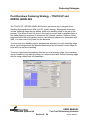
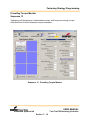
Fastening Strategy Programming
(Advanced Application Builder)
Fastening Strategies
Sequence 10
Sequence 11
Sequence 13
Sequence 15
Sequence 16
Sequence 20
Sequence 20PTR
Sequence 30
Sequence 30PTR
Sequence 31
Sequence 33
Sequence 41
Sequence 46
Sequence 48
Sequence 50
Sequence 51
Sequence 63
Sequence 73
Sequence 75
Sequence 78
Sequence 80
Parameter
Set 193
Engagement Stage
High Speed Rundown
Free Rundown
Frictional Measurement
Event-dependent Turning
Torque Control + Torque Monitor
Torque Control, Pulse Torque Recovery
Torque Control, Angle Monitor
Torque Control, Angle Monitor, Pulse Torque
Recovery
Torque Control with Reverse Analysis
Switch-off Torque Control
Angle Control Backoff
Angle and Torque Control Backoff
Angle Control Backoff + Residual Torque
Angle Control, Torque Monitor
Angle Control with Reverse Analysis
Yield Point Control
Torque Control with Gradient Monitor
Angle Control with Gradient Monitor
Torque and Angle Control with
Gradient Monitor
Torque and Angle Control + Angle
and Torque Monitor
Relax
7-1
7-10
7-12
7-14
7-18
7-21
7-23
7-25
7-28
7-30
7-33
7-39
7-42
7-44
7-46
7-49
7-51
7-58
7-63
7-67
7-71
7-75
7-78
SECTIONS EIGHT thru ELEVEN (not released)
Navigator Selections
USER MANUAL
Tork-Trak TM Fastening Controller
Automated Systems
Section 0 – iii
version: draft 0.5
CONTENTS
SECTION TWELVE
Input – Output Overview
Input-Output Overview
CPU and Display Sub Assembly
Private Output Pinout
Private Input Pinout
Public Output Pinout
Public Input Pinout
Discrete Physical I-O Setup
Public I-O Interface Board and Bus Jumpers
Tork-Trak Default Public Configuration
Wire Jumpers for Public I-O Setup
I-O Setup Instructions
12-1
12-2
12-3
12-4
12-5
12-6
12-7
12-8
12-9
12-9
12-11
SECTION THIRTEEN and FOURTEEN (not released)
Ether Net and Fieldbus
SECTION FIFTEEN
TM Servo Modules
TM12 960900 and TM34 960901
Fault Codes Table
15-1
15-24
SECTION SIXTEEN
TM Servo Module
TMH 960902
Fault Codes Table
16-1
16-25
USER MANUAL
Tork-Trak TM Fastening Controller
Automated Systems
Section 0 – iv
version: draft 0.5
CONTENTS
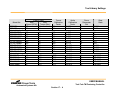
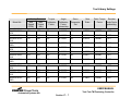
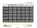
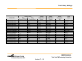
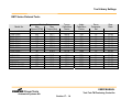
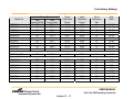
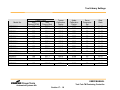
SECTION SEVENTEEN
Tool Library Settings
Cleco Handtools
DGD Fixtured Tools
Rotor Tools
EMT Series Fixtured Tools
17-1
17-5
17-9
17-14
SECTION EIGHTEEN
Recommended Spare Parts
Recommended Spare Parts
18-1
USER MANUAL
Tork-Trak TM Fastening Controller
Automated Systems
Section 0 – v
version: draft 0.5
Introduction to the Tork-Trak TM Controller
SECTION 1
Introduction to the Tork-Trak TM Controller
The Tork-Trak TM Fastening Controller (T3M) is a single channel nutrunner controller
with software capability to run additional tools by connecting to satellite servo modules.
The T3M controller is the fifth generation design of this product and provides greater
functionality than earlier models. A number of improvements have been added. The
basic design of the TM3 controller includes the functionality of the Cooper Power Tool
TM Servo Module combined with a Celeron CPU running TM Multi-Trak Software.
Control signals from the CPU command the Servo Module which in turn controls the
nutrunner to achieve user-programmable torque and angle targets. Statistical results
are saved, calculated, sorted and can be viewed on screen. In addition, the controller
can be used for joint analysis by displaying or saving a digital file of torque vs. angle
fastening rundown O'scope graphics which can be read or printed by any laptop or
desktop computer. The high resolution LCD display provides the user with multi-color
graphics supporting a wide variety of fastening system applications.
USER MANUAL
Tork-Trak TM Fastening Controller
Automated Systems NA
Section 1 - 1
version: draft 0.5
Introduction to the Tork-Trak TM Controller
Some of the features of the T3M controller include:
• NEMA 12 enclosure design
• TM Multi-Trak software which is the same software used on Cooper Power Tools
Automated Systems multiple-spindle panels, so there’s no need to learn different
programming procedures on fixtured tools and handtools.
• Improved PC/104 Celeron CPU with extremely compact design, lower power
consumption, wide operating temperature range, and very high reliability.
• Improved Servo Amplifier design with accurate speed control as low as 3 rpm
through max speed. The new servo amplifier integrates transducer and resolver
measurements with the servo power functions within a single compact module.
• Remote I/O support which has optically isolated inputs and relay contact outputs
which are externally accessible fuse protected,.
• New firmware support which includes global memory, graphical fastening strategy
programming screens supporting Torque Control, Angle Control, Self-Tap, Prevailing
Torque and Yield fastening strategies.
• Software support to permit synchronization of multiple Tork-Trak servos for multispindle applications.
• Increased support for an unlimited number of Applications.
• Communications support for USB, EtherNet, Fieldbus and 2 channel Ethernet
carrying Data and Virtual I/O
Ease of Programming
Cooper Power Tools Automated Systems has designed the Tork-Trak TM to provide an
intuitive programming environment which helps reduce errors. The main features of the
Tork-Trak TM which simplify and reduce your programming time are:
•
•
•
•
•
•
•
•
The Tool Library.
Support of tools with memory chip.
Graphical display of Fastening Curves and Set Points.
Ability to edit the program while continuing to perform fastening rundowns.
Statistics Reporting
Internal O'Scope function for joint and process analysis
Histogram, X-bar and Range charts for process control.
Diagnostics for tool, transducer and communications.
USER MANUAL
Tork-Trak TM Fastening Controller
Automated Systems NA
Section 1 - 2
version: draft 0.5
Introduction to the Tork-Trak TM Controller
Tool Library
The Tork-Trak TM provides a (user programmable) tool library containing setup
information for every electric tool manufactured by Cooper Power Tools. If the tool is
equipped with a memory chip, the tool automatically identifies itself to the CPU and
uploads the tool parameters. If the tool does not have a memory chip, the Tool Library
can be manually accessed to install the correct tool parameters by choosing the tool
Model Number. After selecting a tool from the library, the Tork-Trak TM automatically
programs the appropriate torque transducer and angle encoder calibration values for
that nutrunner.
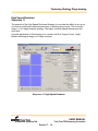
LCD Display Graphics
The Tork-Trak has an LCD display using TFT LCD technology and high speed video
communication with a resolution of 1024 by 768 pixels. This display also provides the
user with the ability to view an 8 ½ inch screen in full color with graphical
representations of torque curves and set points. Screens which graphically represent
the Torque/Angle curves allow you to edit set points for your specific fastening
application.
Fastening Strategies
The power of Cooper Automation's TM Servo Module allows you to program theTorkTrak for basic or advanced fastening strategies. The following fastening strategies are
available and easy to program and are a subset of the two dozen available fastening
strategies.
•
•
•
•
•
•
Torque Monitor
Torque Control / Angle Monitor
Angle Control / Torque Monitor
Prevailing Torque Monitor
Yield Point Control
Yield Point Control with Gradient Monitoring
USER MANUAL
Tork-Trak TM Fastening Controller
Automated Systems NA
Section 1 - 3
version: draft 0.5
Introduction to the Tork-Trak TM Controller
Statistics Reporting
The Statistical Process Control functions of the Tork-Trak TM controller are capable of
meeting your present production demands today and years into the future. The RUN
Screen dynamically indicates Torque X-bar, Range, Sample Number, Sample Size and
CpK after every fastening rundown. The Stats Menu and Print Menu screens offer
custom format options which allow you to produce reports specific to your needs:
• Statistics Report
• Application History Report
• Chronological History Report
• Histogram
• X-bar and Range Charts
• Fault Log
Other Features
Diagnostics
•
•
•
•
Torque/Angle Curve (O'scope Curve)
Tool Tests
Tork-Trak Self Tests
Fault Log
Outputs
•
•
•
•
EtherNet port
USB port
Field Bus Support of Devicenet, Profibus or Interbus (options)
Six Fastening Accept / Reject Indicator Lights + Two User programmable Indicator
Lights
Peripherals
•
External Keyboard connector
USER MANUAL
Tork-Trak TM Fastening Controller
Automated Systems NA
Section 1 - 4
version: draft 0.5
Introduction to the Tork-Trak TM Controller
Options
•
•
•
•
•
•
•
•
•
•
•
•
•
•
•
•
•
Public I/O port and matching cable connector
RS-232 Serial Connector port
Laser Bar Code Reader
External Application selector switch
External control pendant
External socket tray
Batch Counting Capability
Remote Light Box
Remote Live Handle for Cycle Start
Stack Light Connector Support
GM Common Controller
DeviceNet
Profibus
Interbus
Ethernet IP
Modbus TCP
Interbus 2 channel Data + Virtual I-O
Unpacking
The Tork-Trak TM controller is a fastening system with a minimum of components. In its
basic form, the system consists of the Tork-Trak TM controller enclosure, the fastening
tool and a field cable. During unpacking it is advisable to inspect the equipment for
damage which may have occurred in transit and also to verify that the expected
equipment has actually been received. Check that you have received the proper tool
model and the correct field cable length, as well as any optional equipment you may
have ordered. The first step is to remove the Tork-Trak TM controller unit from its
shipping carton.
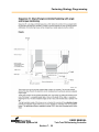
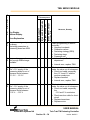
Installation
The Tork-Trak TM controller requires a secure mounting surface capable of supporting
weight of approximately 40 pounds. The selected location should be in an unobstructed
area offering a clear view of the indicator lights and LCD display, and access to the
supplied keyboard. Mount the unit away from major electrical systems, electric motors,
arc welders, and areas experiencing excessive vibration, moisture and heat. Install the
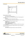
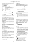
Tork-Trak TM controller utilizing the bolt template provided in Figure 1-1 and allow 12
inches of clearance on the bottom front of the unit for cable connection accessibility.
Mount the unit with four 1/4 inch diameter bolts.
USER MANUAL
Tork-Trak TM Fastening Controller
Automated Systems NA
Section 1 - 5
version: draft 0.5
Introduction to the Tork-Trak TM Controller
Figure 1-1 T3M Enclosure Outline and Mounting Dimensions
USER MANUAL
Tork-Trak TM Fastening Controller
Automated Systems NA
Section 1 - 6
version: draft 0.5
Introduction to the Tork-Trak TM Controller
Connecting the Tool
The field cable and tool can now be connected to the Tork-Trak TM controller. Proper
engagement of the cable connectors is important. Carefully align the connectors and the
lock ring while firmly pushing the connector until it is fully seated. Excessive force is not
required.
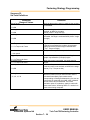
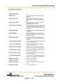
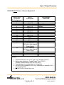
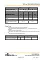
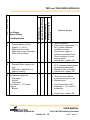
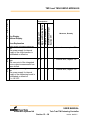
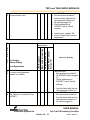
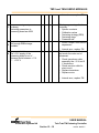
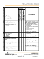
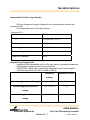
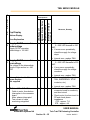
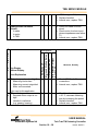
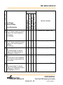
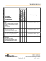
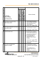
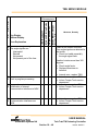
Electrical Requirements
The Tork-Trak TM controller requires a power source of 230 Volts AC, single phase or
230 Volts AC, three phase, 60/50 Hz, with a ground wire, capable of supplying 15
through 20 amperes depending upon the tool model being controlled. Refer to the
following chart for tool model number and power requirements.
Supply
Voltage
VAC
Tool Model
DGD Series 1 Nutrunners
DGD Series 2 Nutrunners
DGD Series 3 Nutrunners
DGD Series 4 Nutrunners
EMT 80 Nutrunners
EMT 200 Nutrunners
EMT 400 Nutrunners
EMT 600 Nutrunners
EMT 800 Nutrunners
EMT 1200 Nutrunners
Cleco Model 17 Series Handtools
Cleco Model 47 Series Handtools
Cleco Model 67 Series Handtools
230V
230V
230V
230V
230V
230V
230V
230V
230V
230V
230V
230V
230V
1Ø
1Ø
3Ø
3Ø
1Ø
1Ø
3Ø
3Ø
3Ø
3Ø
1Ø
1Ø
1Ø
Peak Supply
Current
Amps
Average
Power
KVA
8
16
30
48
10
20
30
40
40
55
8
16
25
0.75
0.75
1.0
1.0
0.75
1.0
1.0
1.0
1.25
1.25
.75
1.0
1.0
Figure 1-2 Controller AC Input Power Requirements
USER MANUAL
Tork-Trak TM Fastening Controller
Automated Systems NA
Section 1 - 7
version: draft 0.5
Introduction to the Tork-Trak TM Controller
Power Drop Wiring
It is recommended that the fuse selection and conductor AWG gage be based on
Average Supply Current shown in the Average Power KVA column in Figure 1-2. Note
that while most of the tools are single phase, six of the tools are three phase. If undersized conductors are used, the delivered torque of the fastening nutrunner will be below
the catalog torque rating. It is recommended that Slow-Blow fuse protection be
considered to prevent nuisance trips from peak current requirements.
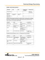
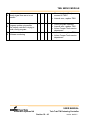
The Tork-Trak TM Controller is shipped with a power drop cable, Cooper Power Tools
Part Number 576166. This same cable can be used for single phase or three phase
operation. One end of the power cable is terminated with a 5 pin connector which plugs
into the power connector bulkhead on the controller enclosure, bottom left rear. The
other end of the cable is un-terminated with a 4 conductor pigtail. The following chart
shows the wiring colors assigned for single and three phase operation:
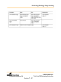
Supply Voltage
Function
Cable 576166 Wire
Color
Single Phase 230 VAC
230 VAC single phase
230VAC single phase
Ground
Black
Red
Green
Three Phase 230 VAC
230 VAC 3 phase
230 VAC 3 phase
230 VAC 3 phase
Ground
Black
Red
White
Green
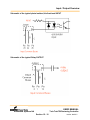
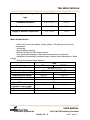
Power Connector Wiring
The following illustration shows the pin view of the power cable connector.
In general, wire Black, Red for single phase controllers and Black, Red, White for three
phase controllers.
USER MANUAL
Tork-Trak TM Fastening Controller
Automated Systems NA
Section 1 - 8
version: draft 0.5
Introduction to the Tork-Trak TM Controller
Power Cable Connector Pin View Wiring
RFI Filtering and Surge Suppression
The central component of the Tork-Trak Controller is a Celeron CPU which under
certain plant conditions could be susceptible to high levels of Radio Frequency
Interference (RFI) or large transient voltage spikes, Electro- Magnetic Interference
(EMI). Both RFI and transient noise are usually transmitted through the plant AC voltage
distribution system. A combination transient suppression and RFI suppression module
is installed in the Tork-Trak TM enclosure which will help protect the operation of the
controller under these types of AC generated noise.
USER MANUAL
Tork-Trak TM Fastening Controller
Automated Systems NA
Section 1 - 9
version: draft 0.5
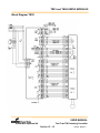
Overview of the Tork-Trak TM Controller
SECTION 2
Overview of the Tork-Trak TM Controller
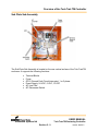
This section is an overview of the hardware components which make up the Tork-Trak
TM controller. Each of these major components will be discussed in detail on a
functional basis. Some of the components under discussion are Optional, and may or
may not be installed in your controller. The major components are:
Tork-Trak TM Controller
Major Hardware Components
•
•
•
•
•
•
T3M Enclosure Top Assembly
CPU and Display Sub-Assembly
Connector Plate Sub-Assembly
Sub-Plate Sub Assembly
TM Servo Module
Keyboard
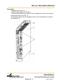
T3M Enclosure Top Assembly
USER MANUAL
Tork-Trak TM Fastening Controller
Automated Systems NA
Section 2 - 1
version: draft 0.5
Overview of the Tork-Trak TM Controller
Power Disconnect
The power disconnect turns the AC drop (single or three phase) ON or OFF. The
disconnect switch may be padlocked in the OFF position. The AC drop enters the
enclosure through a connector mounted on the bottom surface of the enclosure in the
rear left corner.
LCD Display
The LCD Display is a high resolution color monitor with an 8.4 inch XGA TFT Digital
LCD Display Module, and 1024 x 768 pixels resolution.
TM Servo Module
There are three different TM Servo Modules available which supply different values of
peak current. The servos are matched to different tools to deliver specific ranges of
rated torque. The servo also evaluates outputs from the torque transducer and resolver.
All fastening strategies (sequences) are resident within the Servo Module firmware.
TMH Servo
Used with all Cleco hand tools and Rotor Tools. Rated at 40 amps peak current.
TM12 Servo
Used with all Series 1 and 2 DGD fixtured spindles. Also used with EMT 80 and EMT
200 fixtured tools. Servo rated at 22 amps peak current.
TM34 Servo
Used with all Series 3 and 4 DGD fixtured spindles. Also used with EMT 400, EMT 600
and EMT 800 fixtured tools. Rated at 66 amps peak current.
USER MANUAL
Tork-Trak TM Fastening Controller
Automated Systems NA
Section 2 - 2
version: draft 0.5
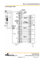
Overview of the Tork-Trak TM Controller
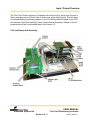
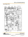
CPU and Display Sub-Assembly
The CPU and Display Sub Assembly contains the following major components:
• LCD Display
• Indicator Lights and Overlay Lens
• Hard Drive
• CPU / Mother Board (PC-104 Bus)
• PC-104 I/O Board
• PC-104 FieldBus Board
• DeviceNet
• Profibus
• PC-104 ArcNet Board
• Indicator Light Board Assembly
• Private I/O Interface Board Assembly
• Public I/O Interface Board Assembly
USER MANUAL
Tork-Trak TM Fastening Controller
Automated Systems NA
Section 2 - 3
version: draft 0.5
Overview of the Tork-Trak TM Controller
USER MANUAL
Tork-Trak TM Fastening Controller
Automated Systems NA
Section 2 - 4
version: draft 0.5
Overview of the Tork-Trak TM Controller
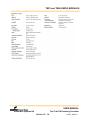
CPU
The CPU and Mother Board is an extremely compact, low power design supporting the
PC-104 bus with a wide operating temperature range 0 to 60 degrees C.. The CPU is a
low voltage Celeron with a clock speed of 650 MHz. The memory is 256 MB SDRAM.
The MotherBorad supports RS-232 serial, USB 1.1, Ethernet 10/100 and an EIDE Hard
Drive port.
The operating system is Microsoft Windows 2000 Professional.
The fastening application software is Cooper Automated Systems TM Multi-Trak, the
same software used in the Cooper Power Tools larger 32 spindle panels.
Indicator Lights
USER MANUAL
Tork-Trak TM Fastening Controller
Automated Systems NA
Section 2 - 5
version: draft 0.5
Overview of the Tork-Trak TM Controller
Indicator Light Definitions
TORQUE HIGH
(RED)
TORQUE LOW
(YELLOW)
Indicates that the last fastening sequence has
exceeded the acceptable final high torque set
point.
Indicates that the last fastening sequence is
below the acceptable final low torque set point.
CYCLE REJECT
(RED)
Indicates that one or more characteristics of the
last fastening cycle is unacceptable.
CYCLE
ACCEPT
(GREEN)
Indicates that the last fastening sequence has
fallen within the acceptable range of the torque
and angle set points
FINAL ANGLE
HIGH
(RED)
Indicates that the last fastening sequence has
exceeded the acceptable final angle high set
point.
FINAL ANGLE
LOW
(YELLOW)
UNMARKED
(BLUE)
UNMARKED
(BLUE)
Indicates that the last fastening sequence is
below the acceptable final angle low set point.
Indicator can be mapped to any programmed
available output by the User.
Indicator can be mapped to any programmed
available output by the User.
Hard Drive
The hard drive is a 40 Gb Hard Drive, Laptop Notebook style. This style of hard drive is
very rugged with high reliability and low susceptance to shock and vibration. The Hard
Drive stores the TM Multi-Trak application software, the operating system and all
database fields which includes rundown data and fastening setup parameters.
ArcNet Coupler Board
The ArcNet coupler board is a PC-104 bus board which plugs into the CPU Mother
Board. The ArcNet board communicates information and data between the Mother
Board CPU and the TM Servo Module.
USER MANUAL
Tork-Trak TM Fastening Controller
Automated Systems NA
Section 2 - 6
version: draft 0.5
Overview of the Tork-Trak TM Controller
Input / Output Board
The I/O board is a PC-104 board which supporting 8 Inputs and 8 Outputs. The Inpits
are opto coupled and the Outputs are relay contacts. The Inputs are bi-polar which
support active high or active low inputs, sink or source. The I/O board suports inputs
and outputs to both the Public I/O and the Private I/O external enclosure connectors.
FieldBus (Option)
DeviceNet Board
The DeviceNet board is a slave to the plant public, virtual fieldbus. The DeviceNet board
sends or receives virtual discrete I/O signals between the Tork-Trak TM controller and
the plant PLC head end. Devicenet software drivers are installed as part of the FieldBus
DeviceNet option.
The DeviceNet plant cable drop enters the enclosure through a connector mounted on
the bottom surface of the enclosure in the front right corner.
Power Supply
The power supply is located in the upper right section of the enclosure, mounted to the
subplate and generates plus & minus 5 VDC, and plus & minus 12 VDC. The power
supply is common to the PC/104 CPU, Hard Drive and all PC-104 Boards.
USER MANUAL
Tork-Trak TM Fastening Controller
Automated Systems NA
Section 2 - 7
version: draft 0.5
Overview of the Tork-Trak TM Controller
Connector Plate Sub Assembly
The Connector Plate Sub Assembly is located on the bottom front of the Tork-Trak TM
enclosure. It provides eight connectors supporting the following functions:
•
•
•
•
•
•
•
•
EtherNet Port
USB Port
Keyboard Port
Mouse port
24 VDC I / O Fuse
Public I / O Connector
Private I / O Connector
Tool Connector (fixtured tool connector or hand tool connector)
USER MANUAL
Tork-Trak TM Fastening Controller
Automated Systems NA
Section 2 - 8
version: draft 0.5
Overview of the Tork-Trak TM Controller
Sub Plate Sub-Assembly
The Sub Plate Sub Assembly is located on the rear vertical surface of the Tork-Trak TM
enclosure. It supports the following functions:
•
•
•
•
•
•
Terminal Blocks
Fuses
GFCI (Ground Fault Circuit Interruptor) 1 or 3 phase
Power Supply, 24 VDC, 5 VDC, 12 VDC
AC Line Filter
AC Disconnect Switch
USER MANUAL
Tork-Trak TM Fastening Controller
Automated Systems NA
Section 2 - 9
version: draft 0.5
Overview of the Tork-Trak TM Controller
TM Servo Module
There are three different TM Servo Modules available which supply different values of
peak current. The servos are matched to different tools to deliver specific ranges of
rated torque. The servo also evaluates outputs from the torque transducer and resolver.
All fastening strategies (sequences) are resident within the Servo Module firmware.
TMH Servo
Used with all Cleco hand tools and Rotor Tools. Rated at 40 amps peak current.
TM12 Servo
Used with all Series 1 and 2 DGD fixtured spindles. Also used with EMT 80 and EMT
200 fixtured tools. Servo rated at 22 amps peak current.
TM34 Servo
Used with all Series 3 and 4 DGD fixtured spindles. Also used with EMT 400, EMT 600
and EMT 800 fixtured tools. Rated at 66 amps peak current.
USER MANUAL
Tork-Trak TM Fastening Controller
Automated Systems NA
Section 2 - 10
version: draft 0.5
Overview of the Tork-Trak TM Controller
Keyboard and Mouse
The Keyboard is full function, 88 keys, and mouse (trackball + 2 keys). (Upper right
corner for the trackball and upper left corner for the mouse function keys)
The end of the keyboard cable splits to two mini-DIn 6 pin connectors. One is for the
keyboard function and the other is for the mouse function. Both connectors plug into the
external connector plate at the bottom of the enclosure. The connector closest to the
front connects the keyboard and the connector closest to the rear connects the mouse.
USER MANUAL
Tork-Trak TM Fastening Controller
Automated Systems NA
Section 2 - 11
version: draft 0.5
Fastening Strategies
SECTION 6
Fastening Strategies (Sequences)
Overview
There are two dynamic measurements which occur when fastening joints using electric
nut runners. The two measurements are Torque and Angle. Torque is the measurement
of rotational force, and Angle is the measurement of the square drive socket rotation
angle in degrees measured after reaching a programmed level of torque. Torque is
measured in foot pounds or Newton Meters and Angle is measured in degrees.
In establishing a fastening strategy for tightening a threaded joint, either Torque or
Angle are chosen as the control function. A strategy can control to a specific Target
Torque value and also monitor the angle, or a strategy can control to a specific Target
Angle and monitor the resulting torque. Using Torque and Angle as control or
monitoring parameters can create a wide variety of specialized Fastening Strategies.
In this Section. the terms Fastening Strategy or Fastening Sequence are used
interchangeably.
The Fastening Sequences discussed on the following pages are included in the TM
Multi-Trak Fastening Control Software, and are available to the Tork-Trak TM Controller
User.
USER MANUAL
Tork-Trak TM Fastening Controller
Automated Systems NA
Section 6 - 1
version: draft 0.5
Fastening Strategies
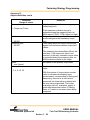
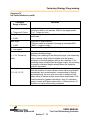
Sequence 10: Engagement Stage
In the electronic control system the maximum evaluation torque, on time, off time and
cycle number of the engagement stages are entered separately for each nutsetter.
A maximum tightening time is entered as the safety shut-down. It applies to all
nutsetters of a product group (tightening process) in this stage.
The engagement stage facilitates the bit and bolt head having firm contact.
For this purpose the nutsetter is operated in both directions alternately. The
engagement stage on time sets the duration of the clockwise and counterclockwise
movements of the nutsetter, the engagement stage off time the length of time after each
movement. An engagement stage cycle consists of a clockwise movement - stop counterclockwise movement - stop.
The measuring transducer integrated into the nutsetter measures the torque during
rundown.
The value is processed by the control system. The nutsetter is stopped when the
evaluation torque is reached or the set number engagement stage cycles has been
completed. The last measured torque is processed in the control system. The control
system can display the values in tables on the monitor and can output them to a printer
or transmit them to other system components by data communication.
The graphics function is not supported in this stage.
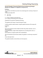
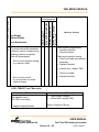
The parameters below are entered in the electronic control system:
Sequence input value:
10
Max. evaluation torque (Nm):
Engagement stage on time (ms):
Engagement stage off time (ms):
Engagement cycles:
Maximum torque at which the engagement
stage is prematurely stopped
The nutsetter remains switched on throughout
this time
The nutsetter remains switched off throughout
this time
Number of engagement stage cycles
Filtering factor:
Filtering factor, number of measured values
used for filtering by averaging
Speed (rpm):
Preset speed; within the maximum speed
range specified in the range for spindle
constants
USER MANUAL
Tork-Trak TM Fastening Controller
Automated Systems NA
Section 6 - 2
version: draft 0.5
Fastening Strategies
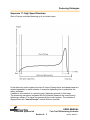
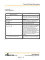
Sequence 11: High Speed Rundown
Shut-off torque controlled fastening up to a contact torque
In the electronic control system the shut-off torque, filtering factor and speed preset are
entered separately for each nutsetter. A maximum tightening time is entered as the
safety shutdown.
It applies to all nutsetters of a product group (tightening process) in this stage.
The measuring transducer integrated into the nutsetter measures the torque during
tightening rundown. The value is processed by the control system. The nutsetter is
stopped when the "shut-off torque" search criteria is reached.
USER MANUAL
Tork-Trak TM Fastening Controller
Automated Systems NA
Section 6 - 3
version: draft 0.5
Fastening Strategies
The peak torque achieved during the dwell time is then measured and processed in the
control system as the bolt tightening torque. The control system can display the values
in tables on the monitor and can output them to a printer or transmit them to other
system components by data communication.
When the spindle trigger torque is reached, recording of the torque curve starts and the
curve can be viewed and evaluated in a graphic.
This tightening method is normally used as the fast pretightening stage.
The parameters below are entered in the electronic control system:
Sequence input value:
11
Trigger torque (Nm):
Trigger torque, beginning of measurement recording for the
graphic display
Shut-off torque (Nm):
Shut-off torque for the high speed rundown
Filtering factor:
Filtering factor, number of measured values used for filtering
by averaging
Speed (rpm):
Preset speed; within the maximum speed range specified in
the range for spindle constants
USER MANUAL
Tork-Trak TM Fastening Controller
Automated Systems NA
Section 6 - 4
version: draft 0.5
Fastening Strategies
Sequence 13: Free Rundown Torque Monitoring (FRTM)
Shut-off torque controlled fastening up to a contact torque with partially monitored
torque monitoring during tightening and subsequent torque analysis.
In the electronic control system the shut-off torque, threshold torque on, maximum
evaluation torque, minimum evaluation torque, threshold torque off, FRTM angle,
unweighted angle, evaluation angle, filtering factor and speed preset are entered
separately for each nutsetter.
A maximum tightening time is entered as the safety shut-down. It applies to all
nutsetters of a product group (tightening process) in this stage.
The measuring transducer integrated into the nutsetter measures the torque and
rotation angle during tightening rundown. The values are processed by the control
system. The torque is monitored from the time when the nutsetter starts until the FRTM
angle is reached. Rundown is terminated immediately with NOK if the maximum
evaluation torque is overstepped in this phase
(phase 1).
USER MANUAL
Tork-Trak TM Fastening Controller
Automated Systems NA
Section 6 - 5
version: draft 0.5
Fastening Strategies
Rundown continues without interruption if phase 1 is error-free. The nutsetter is stopped
when the "shut-off torque" search criteria is reached. The peak torque achieved
during the dwell time is then measured and processed in the control system as the bolt
tightening torque.
In the evaluation phase (phase 2), which is carried out after rundown, the values
recorded between threshold torque on and threshold torque off are evaluated. Torque
values within the unweighted angle starting from threshold torque off are not
considered. Torque values in the subsequent evaluation angle range are checked for
overstep of the maximum evaluation torque and understep of the minimum evaluation
torque.
Oversteps and understeps within the evaluation angle, starting from the recorded
measuring points, are tolerated. The portion of measuring points that may lay outside of
the evaluation torques so as not to trigger a NOK is set with the above limit and below
limit parameters.
A warning is output should this occur.
Any remaining measurements are not considered. The error message "no
measurements present" and NOK are output if the sum of the evaluation angle and
unweighted angle is greater than number of existing measurements (Error message
FSMW "FRTM: Not enough measurement values").
The whole rundown evaluation is processed in the control system. The control system
can display the values as text or in tables on the monitor and can output them to a
printer or transmit them to other system components by data communication.
When the spindle trigger torque is reached, and at the latest when a spindle reaches
threshold torque on, recording of the torque curve starts and the curve can be viewed
and evaluated in a graphic.
The control system can display the values in tables on the monitor and can output them
to a printer or transmit them to other system components by data communication.
This tightening method is normally used as the fast pretightening stage with checked
tightening monitoring and subsequent evaluation.
USER MANUAL
Tork-Trak TM Fastening Controller
Automated Systems NA
Section 6 - 6
version: draft 0.5
Fastening Strategies
The parameters below are entered in the electronic control system:
Sequence input value: 13
Trigger torque (Nm):
Filtering factor:
Shut-off torque (Nm):
Trigger torque, beginning of measurement recording for the
graphic display
Filtering factor, number of measured values used for filtering
by averaging
Shut-off torque for this high speed rundown
Threshold torque On (Nm):
Evaluation angle (deg):
Threshold torque on, beginning of the monitored
range (beginning of angle counting)
Threshold torque off, end of recording for subsequent
evaluation (phase 2)
FRTM angle, length of the monitored range after
the spindle start in phase 1
Range evaluated in phase 2
Unweighted angle (deg):
Range not evaluated in phase 2
Shut-off torque (Nm):
Shut-off torque for the stage
Max. evaluation torque (Nm):
Maximum torque in the monitored range, high
limit in phases 1 and 2
Min. evaluation torque (Nm):
Minimum torque in the monitored range, lower
limit in phase 2
Above limit (%):
Portion of measurements tolerated that lay over
the high limit without triggering NOK (phase 2)
Portion of measurements tolerated that lay below
the low limit without triggering NOK (phase 2)
Preset speed; within the maximum speed range
specified in the range for spindle constants
Jointing-point detection
Threshold torque Off (Nm):
FRTM angle (deg):
Below limit (%):
Speed (rpm):
Jointing-point detection:
USER MANUAL
Tork-Trak TM Fastening Controller
Automated Systems NA
Section 6 - 7
version: draft 0.5
Fastening Strategies
Joint-point Detection
Certain conditions apply that are necessary for exact joint-point detection when this
option is activated in free rundown torque monitoring with sequence 13. These are:
• At least 256 torque values must have been measured during free rundown
torque monitoring.
• Sequence 50 must be the sequence (final fastening) that directly follows this
fastening stage.
• There must have been a high increase in torque at the end of the free rundown
torque monitoring.
This means that the contact torque (shut-off torque) for the free rundown torque
monitoring has to lay significantly above the tightening frictional torque.
A jointing-point is defined as the point at which two or more parts in a severable
connection make connection. A strong increase in torque within a few fastening angles
is indication that such an event has happened.
The precise jointing-point in this pretightening stage can be determined by reevaluating
the recorded torque values and ascertaining the torque increase gradients.
The angle from the jointing-point up to shut-off of the pretightening stage is described as
the jointing-angle.
During jointing-angle detection it is obligatory to use a shut-off controlled tightening
method with rotation angle and torque monitoring (final fastening stage with sequence
50).
The jointing-angle ascertained in the pretightening stage reduces the shut-off angle for
the final fastening stage by the amount of the jointing-angle. This keeps the angle
constant from the jointing-point of the pretightening stage up to standstill of the built-in
nutsetter in the final fastening stage. In turn, this has the effect that the tightening force
of the pretightening stage is also compensated for in the final fastening stage, in order
to prevent overstep of the maximum tightening force of the final fastening stage.
Errors within the tightening method with jointing-point detection are evaluated and are
processed in the control system together with the bolt tightening values. The control
system can display the values in tables on the monitor and can output them to a printer
or transmit them to other system components by data communication.
Note:
The threshold torque in the final fastening stage (sequence 50) should be parametrized
so that it is below the shut-off torque in the pretightening stage (sequence 13) and allows the tightening
method to work correctly with jointing-point detection.
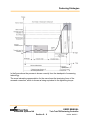
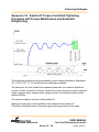
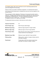
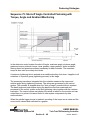
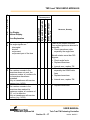
Angle counting stops at the pre-tightening stage shut-off point (diagram 13) and only
continues when the threshold torque of the end fastening stage is reached (diagram 50)
(shut-off angle = joint angle + remaining angle). The parameters for the pre-tightening
stage run-on time (diagram 13), the delay time between the stages and the end tightening stage start
pulse suppression (diagram 50) must be set to "0" here.
Additionally, the threshold torque off should be selected for the pretightening stage
(sequence 13) so that the complete torque rundown is fully recorded in the graphic. This
is the only way to guarantee that the tightening force remains reproducibly constant.
USER MANUAL
Tork-Trak TM Fastening Controller
Automated Systems NA
Section 6 - 8
version: draft 0.5
Fastening Strategies
In the figure above the process is shown correctly from the standpoint of measuring
technology.
The more interesting representation for the user shows the tensioning force of the
screwed connection, which is shown as being equivalent to the tightening torque.
USER MANUAL
Tork-Trak TM Fastening Controller
Automated Systems NA
Section 6 - 9
version: draft 0.5
Fastening Strategies
USER MANUAL
Tork-Trak TM Fastening Controller
Automated Systems NA
Section 6 - 10
version: draft 0.5
Fastening Strategies
Sequence 15: Frictional torque measurement
Frictional torque measurement is started in the same way as a normal rundown cycle
and is carried out fully by the nutsetter control. Frictional torque measurement is divided
into four phases, which are called up and run after one another. The functions below are
executed in the individual phases:
Phase 1: Engagement
The nutsetter is started clockwise and turns until an initiator ("FindINI") reports that the
engaging device (normally a bit) has engaged. The measuring transducer integrated
into the nutsetter measures the torque and rotation angle during the sequence. The
values are processed by the control system. For safety reasons, whenever the "Max.
breakaway torque" oversteps the torque in any phase the nutsetter is stopped and
evaluated as NOK.
USER MANUAL
Tork-Trak TM Fastening Controller
Automated Systems NA
Section 6 - 11
version: draft 0.5
Fastening Strategies
Phase 2: Start Time
Slide out of interference range (SIS) must be set before the nutsetter is started
clockwise. The breakaway torque is monitored in this phase. It must lay within the "Min.
breakaway torque" and "Max. breakaway torque" limits. If this is the case the sequence
continues into phase 3, if this is not the case there is an immediate nutsetter stop.
Phase 3: Frictional Torque Measuring Time
During the frictional torque measuring time the torque is monitored for overstep and
understep of the "Max. evaluation torque" and "Min. evaluation torque" and the
maximum and minimum frictional torques are registered. After the measuring time has
been completed the frictional torque measurement is ended and transition into phase 4
is continuous.
Phase 4: "Engage Upper Dead Center" (move to a defined end position)
During phase 4 the spindle is rotated until an initiator signals it has reached the "upper
dead center position" (upper dead center position DTM, upper dead center "OTINI").
The whole measuring cycle evaluation is processed in the control system. The control
system can display the values in tables on the monitor and can output them to a printer
or transmit them to other system components by data communication.
The parameters below are entered in the electronic control system:
Sequence input value:
15
Max. breakaway torque (Nm):
Safety shut-down torque
Min. breakaway torque (Nm):
Low limit of the breakaway torque for evaluation in the
start time
Max. evaluation torque (Nm):
High evaluation torque during the measuring time
Min. evaluation torque (Nm):
Low evaluation torque during the measuring time
Start time (ms)
Time to overcome the breakaway and to monitor the
backoff torque, determines the length of phase 2
USER MANUAL
Tork-Trak TM Fastening Controller
Automated Systems NA
Section 6 - 12
version: draft 0.5
Fastening Strategies
Measuring time (ms):
Time in which the frictional torque is checked,
determines the length of phase 3
Filtering factor:
Filtering factor, number of measured values used for
filtering by averaging
Speed (rpm):
Preset speed; within the maximum speed range set in
the spindle constants
USER MANUAL
Tork-Trak TM Fastening Controller
Automated Systems NA
Section 6 - 13
version: draft 0.5
Fastening Strategies
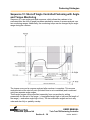
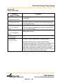
Sequence 16 Event-dependent turning
Positioning Stage
The purpose of this sequence is to stop the built-in nutsetter after a specified position
(initiator position, "FindINI") after a defined angle shut-off value in order, for instance, to
obtain an exact ("upper dead center") position for a machining workpiece.
When the input sequence begins in the tightening process the spindle starts to fasten or
turn.
Angle counting begins after the initiator position has been reached. The built-in nutsetter
stops when the entered shut-off angle is reached. The angle shut-off values reached
are processed in the OK/NOK evaluation. There is no provision to evaluate the reached
torque value.
If the maximum torque is reached during fastening, the spindle shuts off and is given a
NOK evaluation.
The graphics function is not supported in this stage.
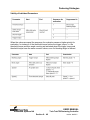
The parameters below are entered in the electronic control system:
Sequence input value:
16
Filtering factor (Nm):
Filtering factor, number of measured values used for
filtering by averaging
Shut-off angle (Nm):
Shut-off angle for the stage
Maximum angle (deg):
Maximum angle, high limit for angle reached and
shutoff value
Minimum angle (deg)
Minimum angle, low limit of angle reached
Maximum torque (Nm)
Maximum torque, high limit of torque reached and
shut-off value
Speed (rpm):
Preset speed; within the maximum speed range
specified in the range for spindle constants
USER MANUAL
Tork-Trak TM Fastening Controller
Automated Systems NA
Section 6 - 14
version: draft 0.5
Fastening Strategies
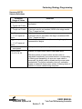
Sequence 20: Shut-off Torque Controlled Fastening with
Torque Monitoring
In the electronic control system the shut-off torque, maximum torque, the minimum
torque, the filtering factor and the speed, are entered separately for each nutsetter.
A maximum tightening time is entered as the safety shut-down.
It applies to all nutsetters of a product group (tightening process) in this stage.
The measuring transducer integrated into the nutsetter measures the torque during
tightening rundown. The value is processed by the control system. The nutsetter is
stopped when the "shut-off torque" search criteria is reached. The peak torque achieved
during the dwell time is then measured and processed in the control system as the bolt
tightening torque together with the rundown evaluation. The control system can display
the values in tables on the monitor and can output them to a printer or transmit them to
other system components by data communication.
When the spindle trigger torque is reached, recording of the torque curve starts and the
curve can be viewed and evaluated in a graphic.
USER MANUAL
Tork-Trak TM Fastening Controller
Automated Systems NA
Section 6 - 15
version: draft 0.5
Fastening Strategies
This tightening method normally follows a fast pretightening stage.
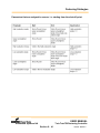
The parameters below are entered in the electronic control system:
Sequence input value:
20
Trigger torque (Nm):
Trigger torque, beginning of measurement recording for the
graphic display
Shut-off torque (Nm):
Shut-off torque for the stage
Maximum torque (Nm):
Maximum torque, high limit of torque reached
Minimum torque (Nm):
Minimum torque, low limit of torque reached
Filtering factor:
Filtering factor, number of measured values used for filtering
by averaging
Speed (rpm):
Preset speed; within the maximum speed range specified in
the range for spindle constants
USER MANUAL
Tork-Trak TM Fastening Controller
Automated Systems NA
Section 6 - 16
version: draft 0.5
Fastening Strategies
Sequence 30: Shut-off Torque Controlled Fastening with
Torque Monitoring and Angle Monitoring
In the electronic control system the shut-off torque, maximum torque, minimum torque,
threshold torque, maximum angle, minimum angle, the filtering factor and the speed are
entered separately for each nutsetter.
The maximum angle is also used as a safety shut-down.
A maximum tightening time is entered as an additional safety shut-down. It applies to all
nutsetters of a product group (tightening process) in this stage.
The measuring transducer integrated into the nutsetter measures the torque and
rotation angle during tightening rundown. The values are processed by the control
system. The angles are counted once the threshold torque is reached. The nutsetter is
stopped when the "shut-off torque" search criteria is reached. The dwell angle and
peak torque achieved during the dwell time are then measured and processed in the
control system as the bolt tightening value together with the rundown evaluation. The
control system can display the values in tables on the monitor and can output them to a
printer or transmit them to other system components by data communication.
When the spindle trigger torque is reached, recording of the torque curve starts and the
curve can be viewed and evaluated in a graphic.
USER MANUAL
Tork-Trak TM Fastening Controller
Automated Systems NA
Section 6 - 17
version: draft 0.5
Fastening Strategies
This tightening method normally follows a fast pretightening stage.
The parameters below are entered in the electronic control system:
Sequence input value:
30
Trigger torque (Nm):
Trigger torque, beginning of measurement recording for the
graphic display
Threshold torque (Nm): Threshold torque, beginning of angle counting
Shut-off torque (Nm):
Shut-off torque for the stage
Maximum torque (Nm):
Maximum torque, high limit of torque reached
Minimum torque (Nm):
Minimum torque, low limit of torque reached
Maximum angle (deg):
Maximum angle, high limit for angle reached and safety
shut-off value
Minimum angle (deg):
Minimum angle, low limit of angle reached
Filtering factor:
Filtering factor, number of measured values used for filtering
by averaging
Speed (rpm):
Preset speed; within the maximum speed range specified in
the range for spindle constants
USER MANUAL
Tork-Trak TM Fastening Controller
Automated Systems NA
Section 6 - 18
version: draft 0.5
Fastening Strategies
Sequence 31:
Shut-off Torque Controlled Fastening with Torque
Monitoring and Angle Monitoring
Sequence 31 is a torque-controlled sequence, which allows the rundown to be
evaluated after the shut-off torque has been reached by means of reverse analysis over
two monitoring ranges.
The torque curve can be reverse analyzed after rundown is complete. This reverse
analysis
starts at the shut-off point (the dwell time is not considered) and is achieved using two
separate
angle ranges.
These angle ranges can be specified separately from one another by setting
parameters for the
end of the range ( = unweighted angle high or low) and the length of the range ( =
evaluation
angle high or low). The two evaluation angles can be in any order and also fully or
partially overlap.
USER MANUAL
Tork-Trak TM Fastening Controller
Automated Systems NA
Section 6 - 19
version: draft 0.5
Fastening Strategies
The high evaluation angle of the torque curve is checked for overstep of the high
evaluation torque and the low evaluation angle of the torque curve is checked for
understep of the low evaluation torque. The tightening process is assessed as being
NOK if there were oversteps and/or understeps.
The maximum torque is measured within the high evaluation angle, and the lowest
torque value within the low evaluation angle and statistical evaluation is carried out.
The evaluation torques can be deactivated by setting the corresponding evaluation
angle to zero.
In the block angle range, which begins directly after the start pulse suppression, the
torque must not exceed the shut-off torque as this will stop the drive. This serves to
detect rundowns that are carried out on a tightened bolt. The block angle can be
deactivated by setting it to zero.
The torque curve is recorded for the graphic starting from the trigger torque (1 torque
value per angle degree). These values are also the basis for the reverse analysis.
Therefore, the trigger torque must be parametrized so that the torque curve relevant for
reverse analysis is always recorded!
An error message with NOK evaluation is generated if there are insufficient torque
values for reverse analysis. The torque curve can be output as a graphic.
Parameters can be set for a blanking angle that starts when trigger torque is reached.
During the blanking angle, detection of the threshold torque and shut-off torque is
deactivated and is only reactivated after the blanking angle has finished.
It is permissible for the torque to be higher than the shut-off torque in the blanking
angle, but the safety shut-down torque must not be exceeded. The drive is stopped
when the safety shut-down torque is exceeded, which applies in the sequence from the
end of the impulse suppression time up to the shut-off point. An error message with
NOK evaluation is generated. The blanking angle can be deactivated by setting it to
zero.
If the block angle and blanking angle overlap, the shut-off torque is considered to be a
termination criteria until the end of the block angle.
Angle counting starts when the threshold torque is reached if detection of the
threshold torque has not been deactivated by the block angle or blanking angle.
Note: If the threshold torque = trigger torque, then angle counting starts when the
threshold torque is reached and continues in the blanking angle.
USER MANUAL
Tork-Trak TM Fastening Controller
Automated Systems NA
Section 6 - 20
version: draft 0.5
Fastening Strategies
Angle measurement and possibly also redundancy monitoring starts when the drive
starts.
After the shut-off torque has caused a shut-down, the torque and/or the corresponding
angle are compared to the minimum/maximum torque and the minimum/ maximum
angle and evaluated accordingly as OK or NOK. Reverse analysis is also carried out.
The maximum angle, safety shut-down torque and maximum tightening time for the
stage are used as a safety shut-down.
Description of parameters
Sequence input value:
31
Filtering factor:
Number of measured torque values used for averaging
Trigger torque (Nm):
Beginning of storing torque values for the graphic display,
reverse analysis and blanking angle
Threshold torque (Nm): Beginning of angle counting; valid outside the blanking angle
and block angle
Shut-off torque (Nm):
Torque at which the drive is stopped and the
dwell time begins; valid outside the blanking angle
Safety shut-down torque (Nm): Monitoring torque valid after start pulse suppression
has finished and during the rundown, and
the value at which the drive is stopped when it is
exceeded
Block angle (deg):
Angle, beginning at the end of start pulse suppression,
in which the torque must be lower than the shut-off torque
Blanking angle (deg):
Angle range starting at the trigger torque, in which the shutoff torque and threshold torque are invalid
Unweighted angle high (deg): End point of the evaluation angle high, related to
the shut-off point (reverse)
Evaluation angle high (deg):
Length of the monitored range for overstep of the
high evaluation torque
High evaluation torque (Nm):
High torque limit in the evaluation angle high that
must not be exceeded in reverse analysis
USER MANUAL
Tork-Trak TM Fastening Controller
Automated Systems NA
Section 6 - 21
version: draft 0.5
Fastening Strategies
Unweighted angle low (deg):
Evaluation angle low (deg):
Low evaluation torque (Nm):
End point of the evaluation angle low, related to
the shut-off point (reverse)
Length of the monitored range for understep of
the low evaluation torque
Low torque limit in the evaluation angle low that
must not be understepped in reverse analysis
Maximum torque (Nm):
High limit of torque reached
Minimum torque (Nm):
Low limit of torque reached
Maximum angle (deg):
High limit for angle reached and safety shut-off value
Minimum angle (deg):
Low limit of angle reached
Speed 1 (rpm):
Preset speed; maximum speed specified in the
range for spindle constants, valid from the beginning
of the sequence up to the threshold torque
Speed when the shut-off torque is reached. Must
be lower than speed 1.
Cutoff is deactivated when speed 2 = 0 or
speed 2 >= speed 1.
Speed 2 (rpm):
When the values are equal the sequence for evaluation causes a higher priority for
evaluation, for instance, of the threshold torque before the trigger torque, i.e. the
threshold torque and thus angle counting are activated when the trigger torque and
threshold torque have the same numeric values, even if a blanking angle is defined.
USER MANUAL
Tork-Trak TM Fastening Controller
Automated Systems NA
Section 6 - 22
version: draft 0.5
Fastening Strategies
Parameters that are analyzed in reverse, i.e. starting from the shut-off point:
USER MANUAL
Tork-Trak TM Fastening Controller
Automated Systems NA
Section 6 - 23
version: draft 0.5
Fastening Strategies
Sequence 33 Switch-off Torque Controlled Tightening
Procedure with Torque Maintenance and Automatic
Retightening
This tightening procedure must be preceded by a pre-clamping Sequence. Sequences
30, 31, 50 51, 63, 73, 75, and 80 show the clamping procedures.
The electronics for each spindle have separate parameters for number of repetitions,
on-time, off-time, the switch-off torque, maximum moment, minimum moment, maximum
angle, minimum angle, damping factor, trigger moment, the threshold torque and the
specified RPM’s.
The maximum angle is used as a safety switch-off.
Maximum running time is also specified as an additional safety switch-off.
This affects all spindle drivers of a product group (driving process) in this stage.
USER MANUAL
Tork-Trak TM Fastening Controller
Automated Systems NA
Section 6 - 24
version: draft 0.5
Fastening Strategies
The torques and angles of rotation during an operation are measured and processed in
a sensing element built into the drivers.
The angles are measured once the threshold moment has been achieved. The driver is
operated alternately between rotary motion and maintaining the desired torque. Upon
reaching “Switch-off Torque”. the driver is stopped and the switch-off torque is
maintained, preventing mechanical relief of the spindle. During the off-time, the
mechanical settling can take place. When the off-time has expired, or if the torque falls
below the specified minimum, the spindle starts again with the specified RPM. When the
on-time has expired, or if “Switch-off torque” has been exceeded, the spindle is
stopped again and the switch-off moment is maintained. One cycle consists of one ontime and one off-time. The number of cycles equals the number of specified repetitions.
During the run-down time, the caster angle and peak torque are measured. An
automatic, slow and controlled relief of the spindle takes place during the specified rundown time, until torque falls below the specified threshold.
The tightening values of the bolt and a reading of the fastened joint are sent to the value
analyzer.
This Sequence can display the values in tabular form on the monitor and / or output to a
printer, as well as transmit this information to other network clients.
Once a spindle reaches the specified trigger moment, the rotation angle is recorded and
can be displayed and evaluated via the graphic function.
The following parameters can be input to the driver electronics:
Diagram input value:
33
Switch-off torque (Nm)
Stage switch-off torque
Maximum torque (Nm):
Maximum torque, upper limit of achieved torque
Minimum torque (Nm)
Minimum torque, lower limit of achieved torque
Maximum angle (grd):
Maximum angle, upper limit of achieved angle and
safety switch-off torque
Minimum angle (grd):
Minimum angle, lower limit of achieved angle
USER MANUAL
Tork-Trak TM Fastening Controller
Automated Systems NA
Section 6 - 25
version: draft 0.5
Fastening Strategies
Threshold torque (Nm):
Threshold torque, start of angle counter
Threshold moment (Nm)
Trigger moment, start of value recording for graphic
display
Number of repetitions:
Number of repetitions of THC on-time and THC
off-time
THC on-time (ms):
The spindle remains switch-on for the duration of this
period, as long as the switch-off torque has not been
achieved
THC off-time (ms):
The spindle remains in hold mode as long as the
minimum torque is maintained
Damping factor
Damping factor, number of measured values based
on averaging applied to damping
RPM
RPM selection; in the range of specified maximum
RPM’s in the spindle constants
USER MANUAL
Tork-Trak TM Fastening Controller
Automated Systems NA
Section 6 - 26
version: draft 0.5
Fastening Strategies
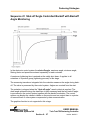
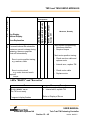
Sequence 41 Shut-off Angle Controlled Backoff with Backoff
Angle Monitoring
In the electronic control system the shut-off angle, maximum angle, minimum angle,
filtering factor and speed are entered separately for each nutsetter.
A maximum tightening time is entered as the safety shut-down. It applies to all
nutsetters of a product group (tightening process) in this stage.
The measuring transducer integrated into the nutsetter measures the angle during backoff. The value is processed by the control system. Angles are counted from the start.
The nutsetter is stopped when the "shut-off angle" search criteria is reached. The
dwell angle achieved during the dwell time is then measured and the bolt backoff angle
is processed in the control system together with the backoff evaluation. The control
system can display the values in tables on the monitor and can output them to a printer
or transmit them to other system components by data communication.
The graphics function is not supported in this stage.
USER MANUAL
Tork-Trak TM Fastening Controller
Automated Systems NA
Section 6 - 27
version: draft 0.5
Fastening Strategies
The backoff torque is defined as being the force that must act upon a fastened joint in
the specified direction in order to overcome the total of the pressing and frictional forces
and thus back-off the fastener.
The parameters below are entered in the electronic control system:
Sequence input value:
41
Shut-off angle (Nm):
Shut-off angle, backoff angle
Maximum angle (deg):
Maximum angle, high limit of angle reached
Minimum angle (deg):
Minimum angle, low limit of angle reached
Filtering factor:
Filtering factor, number of measured values used for
filtering by averaging
Speed (rpm):
Preset speed; within the maximum speed range
specified in the range for spindle constants
In the figure above the process is shown correctly from the standpoint of measuring technology in which
the measured torque is shown as being negative. The more interesting representation for the user shows
the tensioning force of the screwed connection, which is shown below as being positive (equivalent to the
tightening torque).
USER MANUAL
Tork-Trak TM Fastening Controller
Automated Systems NA
Section 6 - 28
version: draft 0.5
Fastening Strategies
Sequence 46: Shut-off Angle and Shut-off Torque Controlled
Releasing Strategy with Angle and Torque Monitoring
Releasing Backoff Strategy with Freely Programmable
Parameter Values
Seizing between the bolt head and bit often occurs during fastening. It can then be
difficult to separate the tool from the workpiece, or an aid must be used for separation.
Seizing occurs very frequently at high torques and / or with certain mechanical fixtures.
The spindle motor release may possibly not be transferred to the workpiece adaptor
when the motor is shut off.
For this reason, a release can be carried out as the last operation in the automatic
tightening process in the electronic control system. This should allow disconnection
from the workpiece to be problem-free. This is achieved by reversing the fastening unit.
USER MANUAL
Tork-Trak TM Fastening Controller
Automated Systems NA
Section 6 - 29
version: draft 0.5
Fastening Strategies
The releasing stage, which can be switched on and off, has fixed parameters that
cannot be changed for this reversing.
Sequence 46 must be used for individual configuration. It is important here that the
force closure for the fastened parts is released and never has more force applied in the
reverse direction.
This would result in further tightening. Furthermore, the screwed connection can be
backed off. The angle range that occurs for release is dependent upon the mechanical
construction of the fastening unit. The stiffer the fastening mechanics and the more
formfitting the tool (bit, square drive, ..), the smaller the releasing angle.
The graphics function is not supported in this stage.
The parameters below are entered in the electronic control system:
Sequence input value:
46
Shut-off angle (deg):
Shut-off angle, backoff angle
Maximum angle (deg):
Maximum angle, high limit of angle reached
Minimum angle (deg):
Minimum angle, low limit of angle reached
Shut-off torque (Nm):
Shut-off torque, shut-off value, that should prevent the
screwed connection from backing off
Maximum torque (Nm):
Maximum torque, high limit of torque reached
Filtering factor:
Filtering factor, number of measured values used for
filtering by averaging
Speed (rpm):
Preset speed; within the maximum speed range
specified in the range for spindle constants
USER MANUAL
Tork-Trak TM Fastening Controller
Automated Systems NA
Section 6 - 30
version: draft 0.5
Fastening Strategies
Sequence 48 Shut-off Angle Controlled Fastening with
Backoff Angle and Residual Torque Monitoring
Sequence 48 is an angle-controlled sequence in which the two points can be defined at
both of which a minimum and a maximum torque value must not be understepped or
overstepped.
One check is carried out at each of the two points M1 and M2 in order to ascertain
whether M1 min., M1 max. and M2 min., M2 max. torque limits are understepped or
overstepped. Points M1 and M2 are specified by the angle at M1 and angle at M2 from
the threshold torque.
Should the torque at these points not lay within the corresponding min/max limits the
drive is stopped and the rundown data is evaluated as NOK.
The time sequence for the two points is not specified, i.e. M1 can lay to the left or right
of M2 or at M2. The torque check in the points M1 and M2 can be deactivated
individually by setting the angle at M1 or M2 to zero.
USER MANUAL
Tork-Trak TM Fastening Controller
Automated Systems NA
Section 6 - 31
version: draft 0.5
Fastening Strategies
Safety shut-down torque parameters are set as an additional safety cutout. The drive is
stopped when the safety shut-down torque is exceeded, which applies in the sequence
from the end of the impulse suppression time up to the shut-off point. An error message
with NOK evaluation is generated.
The torques at M1 and M2 as well as the maximum torques in the rundown are
measured and the results are included in the statistical evaluation.
Angle counting starts from the threshold torque.
After switch-off due to the backoff angle having been reached, the minimum/maximum
torque and the minimum/maximum angle are used to evaluate the result as OK or NOK.
Parameters can be set for a maximum time, a start pulse suppression time and a dwell
time.
When the trigger torque is reached, recording of the torque curve starts and the curve
can be viewed and evaluated in a graphic.
Description of parameters
Sequence input value:
48
Filtering factor:
Number of measured values used for averaging
Trigger torque (Nm):
Start of storing the torque value for the graphical view
Threshold torque (Nm):
Beginning of angle counting
Backoff angle (deg):
Angle at which the drive is stopped and the dwell time
begins
Angle at M1 (deg):
Angle, at which the torque is checked at a position
between M1 max. and M1 min.; the drive is stopped
when the position lies outside of the range M1 min. to
M1 max.
M1 max. (Nm):
Maximum torque allowed at M1
M1 min. (Nm):
Minimum torque allowed at M1
Angle at M2 (deg):
Angle, at which the torque is checked at a position
between M2 max. and M2 min.; the drive is stopped
when the position lies outside of the range M2 min. to
M2 max.
USER MANUAL
Tork-Trak TM Fastening Controller
Automated Systems NA
Section 6 - 32
version: draft 0.5
Fastening Strategies
M2 max. (Nm):
Maximum torque allowed at M2
M2 min. (Nm):
Minimum torque allowed at M2
Maximum torque (Nm):
High limit of torque reached in the shut-off point
Minimum torque (Nm):
Low limit of torque reached in the shut-off point
Maximum angle (deg):
High limit of angle reached in the shut-off point
and shut-off value
Minimum angle (deg):
Low limit of angle reached in the shut-off point
Speed (rpm):
Preset speed; within the maximum speed range
specified in the range for spindle constants
Safety
shut-down torque (Nm):
Monitoring torque valid after start pulse suppression
has finished and during the rundown, and the value at
which the drive is stopped when it is exceeded
USER MANUAL
Tork-Trak TM Fastening Controller
Automated Systems NA
Section 6 - 33
version: draft 0.5
Fastening Strategies
Sequence 50: Shut-off Angle Controlled Fastening with Angle
and Torque Monitoring
In the electronic control system the shut-off angle, maximum angle, minimum angle,
threshold torque, maximum torque, minimum torque, filtering factor and speed are
entered separately for each nutsetter.
The maximum torque is also used as a safety shut-down. A maximum tightening time is
entered as an additional safety shut-down. It applies to all nutsetters of a product group
(tightening process) in this stage.
The measuring transducer integrated into the nutsetter measures the torque and
rotation angle during tightening rundown. The values are processed by the control
system. The nutsetter is stopped when the "shut-off angle" search criteria is reached.
USER MANUAL
Tork-Trak TM Fastening Controller
Automated Systems NA
Section 6 - 34
version: draft 0.5
Fastening Strategies
The dwell angle and peak torque achieved during the dwell time are then measured and
processed in the control system as the bolt tightening value together with the rundown
evaluation. The control system can display the values in tables on the monitor and can
output them to a printer or transmit them to other system components by data
communication.
When the spindle trigger torque is reached, recording of the torque curve starts and the
curve can be viewed and evaluated in a graphic.
This tightening method normally follows a fast pretightening stage.
The parameters below are entered in the electronic control system:
Sequence input value:
Trigger torque (Nm):
Trigger torque, beginning of measurement recording for the
graphic display
Threshold torque (Nm): Threshold torque, beginning of angle counting
Shut-off angle (deg):
Shut-off angle for the stage
Maximum angle (deg):
Maximum angle, high limit of angle reached
Minimum angle (deg):
Minimum angle, low limit of angle reached
Maximum torque (Nm):
Maximum torque, high limit of torque reached and shut-off
value
Minimum torque (Nm):
Minimum torque, low limit of torque reached
Torque
Filtering factor:
Filtering factor, number of measured values used for filtering
by averaging
Speed (rpm)
Preset speed; within the maximum speed range specified in
the range for spindle constants
USER MANUAL
Tork-Trak TM Fastening Controller
Automated Systems NA
Section 6 - 35
version: draft 0.5
Fastening Strategies
Sequence 51: Shut-off Angle Controlled Fastening with Angle
and Torque Monitoring
Sequence 51 is an angle-controlled sequence, which allows the rundown to be
evaluated after the shut-off angle has been reached by means of reverse analysis over
two monitoring ranges. Additionally, the monitoring torque can be changed by an angle
range during the rundown.
The torque curve can be reverse analyzed after rundown is complete. This reverse
analysis starts at the shut-off point (the dwell time is not considered) and is achieved
using two separate angle ranges.
These angle ranges can be specified separately from one another by setting
parameters for the end of the range ( = unweighted angle high or low) and the length of
the range ( = evaluation angle high or low). The two evaluation angles can be in any
order and also fully or partially overlap.
USER MANUAL
Tork-Trak TM Fastening Controller
Automated Systems NA
Section 6 - 36
version: draft 0.5
Fastening Strategies
The high evaluation angle of the torque curve is checked for overstep of the evaluation
torque and the low evaluation angle of the torque curve is checked for understep of the
low evaluation torque. The tightening process is assessed as being NOK if there were
oversteps and/or understeps.
The maximum torque is measured within the high evaluation angle, and the lowest
torque value within the low evaluation angle and statistical evaluation is carried out.
The evaluation torques can be deactivated by setting the corresponding evaluation
angle to zero.
In the block angle range, which begins directly after the start pulse suppression, the
torque must not exceed the maximum torque as this will stop the drive. This serves to
detect rundowns that are carried out on a tightened bolt. The block angle can be
deactivated by setting it to zero.
The torque curve is recorded for the graphic starting from the trigger torque (1 torque
value per angle degree). These values are also the basis for the reverse analysis.
Therefore, the trigger torque must be parametrized so that the torque curve relevant for
reverse analysis is always recorded!
An error message with NOK evaluation is generated if there are insufficient torque
values for reverse analysis. The torque curve can be output as a graphic.
Parameters can be set for a blanking angle that starts when trigger torque is reached.
During the blanking angle, detection of the threshold torque and maximum torque is
deactivated and is only reactivated after the blanking angle has finished.
It is permissible for the torque to be higher than the maximum torque in the blanking
angle, but the safety shut-down torque must not be exceeded. The drive is stopped
when the safety shutdown torque is exceeded, which applies in the sequence from the
end of the start pulse suppression time up to the shut-off point. An error message with
NOK evaluation is generated. The blanking angle can be deactivated by setting it to
zero.
If the block angle and blanking angle overlap, the maximum torque is considered to be a
termination criteria until the end of the block angle.
Angle counting starts when the threshold torque is reached if detection of the threshold
torque has not been deactivated by the block angle or blanking angle.
Note: If the threshold torque = trigger torque, then angle counting starts when the
threshold torque is reached and continues in the blanking angle. Angle measurement
and possibly also redundancy monitoring starts when the drive starts.
USER MANUAL
Tork-Trak TM Fastening Controller
Automated Systems NA
Section 6 - 37
version: draft 0.5
Fastening Strategies
After the shut-off torque has caused a shut-down, the corresponding angle and/or the
torque are compared to the minimum/maximum angle and the minimum/ maximum
torque and evaluated accordingly as OK or NOK. Reverse analysis is also carried out.
The maximum angle, maximum torque, safety shut-down torque and maximum
tightening time for the stage are used as a safety shut-down.
Description of Parameters
Sequence input value:
Filtering factor:
51
Number of measured torque values used for averaging
Trigger torque (Nm):
Beginning of storing torque values for the
graphic display, reverse analysis and blanking angle
Threshold torque (Nm): Beginning of angle counting; valid outside the
blanking angle and block angle
Safety shut-down torque (Nm):
Monitoring torque valid after start pulse
suppression has finished and during the
rundown, and the value at which the drive is
stopped when it is exceeded
Shut-off angle (deg):
Angle at which the drive is stopped and the dwell
time begins;
Block angle (deg):
Angle, beginning at the end of start pulse
suppression, in which the torque must be lower than
the maximum torque
Blanking angle (deg):
Angle range starting at the trigger torque, in
which the maximum torque and threshold torque
are invalid
Unweighted angle high (deg): End point of the evaluation angle high, related to
the shut-off point (reverse)
Evaluation angle high (deg):
Length of the monitored range for overstep of
the high evaluation torque
High evaluation torque (Nm):
High torque limit in the evaluation angle high
that must not be exceeded in reverse analysis
USER MANUAL
Tork-Trak TM Fastening Controller
Automated Systems NA
Section 6 - 38
version: draft 0.5
Fastening Strategies
Unweighted angle low (deg):
End point of the evaluation angle low, related to
the shut-off point (reverse)
Evaluation angle low (deg):
Length of the monitored range for understep of
the low evaluation torque
Low evaluation torque (Nm):
Low torque limit in the evaluation angle low that
must not be understepped in reverse analysis
Maximum torque (Nm):
High limit of torque reached
Minimum torque (Nm):
Low limit of torque reached
Maximum angle (deg):
High limit for angle reached and safety shut-off
value
Low limit of angle reached
Minimum angle (deg):
Speed 1 (rpm):
Preset speed; maximum speed specified in the
range for spindle constants, valid from the
beginning of the sequence up to the threshold
torque
Speed 2 (rpm 1 ):
Speed when the maximum torque is reached.
Must be lower than speed 1.
Cutoff is deactivated when speed 2 = 0 or
speed 2 7 speed 1
1
The maximum torque is normally not reached; the torque shut-off value is lower than
the maximum torque, so the speed will not fully cut off to speed 2.
.
.
USER MANUAL
Tork-Trak TM Fastening Controller
Automated Systems NA
Section 6 - 39
version: draft 0.5
Fastening Strategies
Validity of Individual Parameters
When the values are equal the sequence for evaluation causes a higher priority for
evaluation, for instance, of the threshold torque before the trigger torque, i.e. the
threshold torque and thus angle counting are activated when the trigger torque and
threshold torque have the same numeric values, even if a blanking angle is defined.
USER MANUAL
Tork-Trak TM Fastening Controller
Automated Systems NA
Section 6 - 40
version: draft 0.5
Fastening Strategies
Parameters that are analyzed in reverse, i.e. starting from the shut-off point
USER MANUAL
Tork-Trak TM Fastening Controller
Automated Systems NA
Section 6 - 41
version: draft 0.5
Fastening Strategies
Sequence 63: Yield Point Controlled Fastening with Torque,
Angle and Gradient Monitoring
Yield point controlled fastening with percentage preset of the shut-off gradients by the
maximum gradient and torque, rotation angle and gradient monitoring.
In the electronic control system the lower gradient, upper gradient, percentage shut-off
value, strobe multiplier, filtering factor, minimum torque, maximum torque, minimum
angle, maximum angle and speed are entered separately for each nutsetter.
The maximum torque, maximum angle as well as the upper and lower gradients are
also used as a safety shut-down.
A maximum tightening time is entered as an additional safety shut-down. It applies to all
nutsetters of a product group (tightening process) in this stage.
The measuring transducer integrated into the nutsetter measures the torque and
rotation angle during tightening rundown. The values are processed by the control
system. The nutsetter is stopped when the "shut-off gradient" (percentage rate of the
currently measured maximum gradient) search criteria is reached. The dwell angle and
peak torque during the dwell time are then measured and processed in the control
system as the bolt tightening value together with the rundown evaluation. The control
system can display the values in tables on the monitor and can output them to a printer
or transmit them to other system components by data communication.
USER MANUAL
Tork-Trak TM Fastening Controller
Automated Systems NA
Section 6 - 42
version: draft 0.5
Fastening Strategies
When the spindle trigger torque is reached, recording of the torque curve starts and the
curve can be viewed and evaluated in a graphic.
This tightening method normally follows a fast pretightening stage.
The parameters below are entered in the electronic control system:
Sequence input value:
63
Trigger torque (Nm):
Trigger torque, beginning of measurement recording
for the graphic display
Threshold torque (Nm):
Threshold torque, beginning of angle counting and
gradient calculation
Perc. shut-off value (%):
Percentage shut-off value, percentage amount of the
measured maximum gradients for the rundown
produces the shut-off value (shut-off gradient)
Minimum gradient (Nm/deg):
Minimum gradient, low limit and safety shut-off value
for the gradient
Maximum gradient (Nm/deg):
Maximum gradient, high limit and safety shut-off value
for the gradient
Strobe multiplier:
Strobe multiplier, spacing in angle impulses of the
filtered measured values used for gradient calculation
Filtering factor:
Filtering factor, number of measured values used for
filtering by averaging
Maximum angle (deg):
Maximum angle, high limit for angle reached and
safety shut-off value
Minimum angle (deg):
Minimum angle, low limit of angle reached
Maximum torque (Nm):
Maximum torque, high limit of torque reached and
shut-off value
Minimum torque (Nm):
Minimum torque, low limit of torque reached
Speed (rpm):
Preset speed; within the maximum speed range
specified in the range for spindle constants
USER MANUAL
Tork-Trak TM Fastening Controller
Automated Systems NA
Section 6 - 43
version: draft 0.5
Fastening Strategies
Sequence 73: Shut-off Torque Controlled Fastening with
Torque, Angle and Gradient Monitoring
In the electronic control system the shut-off torque, maximum torque, minimum torque,
maximum angle, minimum angle, lower gradient, upper gradient, strobe multiplier,
filtering factor and speed are entered separately for each nutsetter. The maximum angle
is also used as a safety shut-down.
A maximum tightening time is entered as an additional safety shut-down. It applies to all
nutsetters of a product group (tightening process) in this stage.
The measuring transducer integrated into the nutsetter measures the torque and
rotation angle during tightening rundown. The values are processed by the control
system. The nutsetter is stopped when the "shut-off torque" search criteria is reached.
The dwell angle and peak torque during the dwell time are then measured and
processed in the control system as the bolt tightening value together with the rundown
evaluation. The control system can display the values as text or in tables on the monitor
and can output them to a printer or transmit them to other system components by data
communication.
USER MANUAL
Tork-Trak TM Fastening Controller
Automated Systems NA
Section 6 - 44
version: draft 0.5
Fastening Strategies
When the spindle trigger torque is reached, recording of the torque curve starts and the
curve can be viewed and evaluated in a graphic.
This tightening method normally follows a fast pretightening stage.
The parameters below are entered in the electronic control system:
Sequence input value:
73
Trigger torque (Nm):
Trigger torque, beginning of measurement recording
for the graphic display
Threshold torque (Nm): Threshold torque, beginning of angle counting and gradient
calculation
Shut-off torque (Nm):
Shut-off torque for the stage
Maximum torque (Nm):
Maximum torque, high limit of torque reached
Minimum torque (Nm):
Minimum torque, low limit of torque reached
Maximum angle (deg):
Maximum angle, high limit for angle reached and
safety shut-off value
Minimum angle (deg):
Minimum angle, low limit of angle reached
Minimum gradient (Nm/deg):
Minimum gradient, low limit of the gradients
Maximum gradient (Nm/deg):
Maximum gradient, high limit of the gradients
Strobe multiplier:
Strobe multiplier, spacing in angle impulses of the
filltered measured values used for gradient calculation
Filtering factor:
Filtering factor, number of measured values used for
filtering by averaging
Speed (rpm):
Preset speed; within the maximum speed range specified
in the range for spindle constants
USER MANUAL
Tork-Trak TM Fastening Controller
Automated Systems NA
Section 6 - 45
version: draft 0.5
Fastening Strategies
Sequence 75: Shut-off Angle Controlled Fastening with
Torque, Angle and Gradient Monitoring
In the electronic control system the shut-off angle, maximum angle, minimum angle,
maximum torque, minimum torque, lower gradient, upper gradient, strobe multiplier,
filtering factor and speed are entered separately for each nutsetter. The maximum
torque is also used as a safety shut-down.
A maximum tightening time is entered as an additional safety shut-down. It applies to all
nutsetters of a product group (tightening process) in this stage.
The measuring transducer integrated into the nutsetter measures the torque and
rotation angle during tightening rundown. The values are processed by the control
system. The nutsetter is stopped when the "shut-off angle" search criteria is reached.
The dwell angle and peak torque during the dwell time are then measured and
processed in the control system as the bolt tightening value together with the rundown
evaluation. The control system can display the values in tables on the monitor and can
output them to a printer or transmit them to other system components by data
communication.
When the spindle trigger torque is reached, recording of the torque curve starts and the
curve can be viewed and evaluated in a graphic.
USER MANUAL
Tork-Trak TM Fastening Controller
Automated Systems NA
Section 6 - 46
version: draft 0.5
Fastening Strategies
This tightening method normally follows a fast pretightening stage.
The parameters below are entered in the electronic control system:
Sequence input value:
75
Trigger torque (Nm):
Trigger torque, beginning of measurement recording
for the graphic display
Threshold torque (Nm): Threshold torque, beginning of angle counting and
gradient calculation
Shut-off angle (deg):
Shut-off angle for the stage
Maximum angle (deg):
Maximum angle, high limit of angle reached
Minimum angle (deg):
Minimum angle, low limit of angle reached
Maximum torque (Nm):
Maximum torque, high limit of torque reached and
shut-off value
Minimum torque (Nm):
Minimum torque, low limit of torque reached
Minimum gradient (Nm/deg):
Minimum gradient, low limit of the gradients
Maximum gradient (Nm/deg):
Maximum gradient, high limit of the gradients
Strobe multiplier:
Strobe multiplier, spacing in angle impulses of the
filtered measured values used for gradient calculation
Filtering factor:
Filtering factor, number of measured values used for
filtering by averaging
Speed (rpm):
Preset speed; within the maximum speed range
specified in the range for spindle constants
USER MANUAL
Tork-Trak TM Fastening Controller
Automated Systems NA
Section 6 - 47
version: draft 0.5
Fastening Strategies
Sequence 78: Shut-off torque and shut-off Angle Controlled
Fastening with Torque, Angle and Gradient Monitoring
In the electronic control system the shut-off torque, shut-off angle, maximum angle,
minimum angle, maximum torque, minimum torque, lower gradient, upper gradient,
strobe multiplier, filtering factor and speed are entered separately for each nutsetter.
A maximum tightening time is entered as the safety shut-down. It applies to all
nutsetters of a product group (tightening process) in this stage.
The measuring transducer integrated into the nutsetter measures the torque and
rotation angle during tightening rundown. The values are processed by the control
system. The nutsetter is stopped when the "shut-off torque" or "shut-off angle" search
criteria is reached. The dwell angle and peak torque during the dwell time are then
measured and processed in the control system as the bolt tightening value together with
the rundown evaluation. The control system can display the values in tables on the
monitor and can output them to a printer or transmit them to other system components
by data communication.
When the spindle trigger torque is reached, recording of the torque curve starts and the
curve can be viewed and evaluated in a graphic.
This tightening method normally follows a fast pretightening stage.
USER MANUAL
Tork-Trak TM Fastening Controller
Automated Systems NA
Section 6 - 48
version: draft 0.5
Fastening Strategies
The parameters below are entered in the electronic control system:
Sequence input value:
78
Trigger torque (Nm):
Trigger torque, beginning of measurement recording
for the graphic display
Threshold torque (Nm): Threshold torque, beginning of angle counting and gradient
calculation
Shut-off torque (Nm):
Shut-off torque for the stage
Shut-off angle (deg):
Shut-off angle for the stage
Maximum angle (deg):
Maximum angle, high limit of angle reached
Minimum angle (deg):
Minimum angle, low limit of angle reached
Maximum torque (Nm):
Maximum torque, high limit of torque reached and
shut-off value
Minimum torque (Nm):
Minimum torque, low limit of torque reached
Minimum gradient (Nm/deg):
Minimum gradient, low limit of the gradients
Maximum gradient (Nm/deg):
Maximum gradient, high limit of the gradients
Strobe multiplier:
Strobe multiplier, spacing in angle impulses of the
filtered measured values used for gradient calculation
Filtering factor:
Filtering factor, number of measured values used for filtering
by averaging
Speed (rpm):
Preset speed; within the maximum speed range specified
in the range for spindle constants
USER MANUAL
Tork-Trak TM Fastening Controller
Automated Systems NA
Section 6 - 49
version: draft 0.5
Fastening Strategies
Sequence 80: Shut-off Torque and Shut-off Angle Controlled
Fastening with Angle and Torque Monitoring
In the electronic control system the shut-off torque, shut-off angle, maximum angle,
minimum angle, threshold torque, maximum torque, minimum torque, filtering factor and
speed are entered separately for each nutsetter.
The maximum torque and the maximum angle are also used as a safety shut-down. A
maximum tightening time is entered as an additional safety shut-down. It applies to all
nutsetters of a product group (tightening process) in this stage.
The measuring transducer integrated into the nutsetter measures the torque and
rotation angle during tightening rundown. The values are processed by the control
system. The nutsetter is stopped when the "shut-off torque" or "shut-off angle" search
criteria is reached. The dwell angle and peak torque achieved during the dwell time are
then measured and processed in the control system as the bolt tightening value
together with the rundown evaluation. The control system can display the values in
tables on the monitor and can output them to a printer or transmit them to other system
components by data communication.
USER MANUAL
Tork-Trak TM Fastening Controller
Automated Systems NA
Section 6 - 50
version: draft 0.5
Fastening Strategies
When the spindle trigger torque is reached, recording of the torque curve starts and the
curve can be viewed and evaluated in a graphic.
This tightening method normally follows a fast pretightening stage.
The parameters below are entered in the electronic control system:
Sequence input value:
80
Trigger torque (Nm):
Trigger torque, beginning of measurement recording for
the graphic display
Threshold torque (Nm): Threshold torque, beginning of angle counting
Shut-off torque (Nm):
Shut-off torque for the stage
Shut-off angle (deg):
Shut-off angle for the stage
Maximum angle (deg):
Maximum angle, high limit for angle reached and safety
shut-off value
Minimum angle (deg):
Minimum angle, low limit of angle reached
Maximum torque (Nm):
Maximum torque, high limit of torque reached and shut-off
value
Minimum torque (Nm):
Minimum torque, low limit of torque reached
Filtering factor:
Filtering factor, number of measured values used for filtering
by averaging
Speed (rpm):
Preset speed; within the maximum speed range specified
in the range for spindle constants
USER MANUAL
Tork-Trak TM Fastening Controller
Automated Systems NA
Section 6 - 51
version: draft 0.5
Fastening Strategies
Pre-Rundown and Post Rundown Fastening Strategies
There are several pre-rundown and post rundown strategies which can be enabled
which attach to a Fastening Sequence. When a pre-rundown strategy is enabled, it will
run before the Stage 1 Sequence begins. When a post-rundown strategy is enabled, it
will run when the last Programmed Stage “n” Sequence has completed the cycle.
Pre-Rundown Fastening Strategies
• Jog
Post Rundown Fastening Strategies
•
•
Touchup and Error Handling
PTR (pulse torque recovery)
USER MANUAL
Tork-Trak TM Fastening Controller
Automated Systems NA
Section 6 - 52
version: draft 0.5
Fastening Strategies
Pre-Rundown Fastening Strategy – JOG
The JOG function provides a way to rotate the tool spindle in short duration intervals for
the purpose of locating the socket(s) on the bolt or nut. Pressing the cycle start lever for
short intervals can be repeated until the sockets are settled on the fastener. No
declaration of OK or NOK is made during the jogs. If the operator holds the cycle start
lever down longer than the programmed jog duration time, the rundown will
automatically proceed to Stage 1 to the end of the rundown.
This procedure describes the enabling of JOG and the JOG parameter programming.
The JOG setup parameters are located on the Advanced Application Builder screen.
1. Click on Navigate, upper left of the screen.
2. Click on Advanced Application Builder.
3. Refer to the following illustration of the Advanced Application Builder screen.
4. On the lower right of the Application Builder Screen is a section labeled
Jog Settings.
5. Place a check mark in the Enable block
6. Enter the Max Torque. If the max torque is exceeded during JOG, the jog
process will stop.
7. Enter the Final Speed. This is the spindle speed during the JOG process.
8. Enter the Duration in msec. JOG intervals less than this interval will not start the
rundown, and can be repeated any number of times at the operator’s discretion.
If the Duration time is exceeded, the rundown cycle will begin automatically
starting with Stage 1. As an example, set the duration at 3000 for a 3 second
JOG duration.
USER MANUAL
Tork-Trak TM Fastening Controller
Automated Systems NA
Section 6 - 53
version: draft 0.5
Fastening Strategies
Post-Rundown Fastening Strategy – TOUCH UP and
ERROR HANDLING
The TOUCH UP / ERROR-HANDLING function provides a way to program ErrorHandling by programming a NOK (not OK, reject) strategy. Subsequent to touch up
another fastening stage may be started, while error-handling leads to the end of the
process. This allows to back off joints in the touch up routine and to retighten these in
the further fastening sequence to achieve an OK (accept) rundown. Since no further
stage can follow the error-handling routine, the fastening sequence is terminated with
NOK, it is often used to fully back out the fasteners.
Touch up and error handling can be programmed separately for each fastening stage,
that is, group assignments and blackout parameters can be entered in each stage for
both touch up and error-handling.
Touch up is performed immediately after the end of a fastening stage. Error-handling
can be initiated by any fastening stage, but will performed after the last fastening stage
with the stage related back off parameters.
USER MANUAL
Tork-Trak TM Fastening Controller
Automated Systems NA
Section 6 - 54
version: draft 0.5
Fastening Strategies
From the Navigate drop down panel (upper left corner of screen), select Advanced
Application Builder. The “Global to the Application” area on the lower right of the
Advanced Application Builder screen contains the parameter settings for Touch Up and
Back out.
Touch Up Settings
•
•
•
Target Angle
High Angle Limit
Final Speed
Backoff Settings
•
•
•
Target Angle
High Angle Limit
Final Speed
USER MANUAL
Tork-Trak TM Fastening Controller
Automated Systems NA
Section 6 - 55
version: draft 0.5
Fastening Strategies
Post-Rundown Fastening Strategy – PTR (Pulse torque
recovery)
The Pulse Torque Recovery (PTR) function provides a way to program torque recovery
by pulsing “make-up” torque at the conclusion of a fastening rundown, and is used most
successfully on joints which are either gasketed, springy sheet metal, or soft metal
(aluminum) where a "make-up torque" is required. If the joint begins to relax
immediately following the rundown, PTR can add a pre-programmed amount of torque
for a pre-programmed time duration if the torque drops below a pre-programmed value.
This strategy was awarded U.S. Patent 5,094,301.
Pulse torque recovery is applied at the conclusion of a fastening rundown, and is used
most successfully on joints which are either gasketed or springy sheet metal, where a
"makeup torque" is required. If the joint begins to relax immediately following the
rundown, Torque Recovery can add a pre-programmed amount of torque for a preprogrammed time duration if the torque drops below a pre-programmed value. This
strategy was awarded U.S. Patent 5,094,301.
PTR can be applied to the final stage attached to either Sequence 20 PTR, Pulse
Torque Recovery or Sequence 30 PTR. Shut-off Torque Controlled Fastening with
Torque Monitoring and Angle Monitoring.
The rundown graphic for Sequence 30 PTR appears below:
USER MANUAL
Tork-Trak TM Fastening Controller
Automated Systems NA
Section 6 - 56
version: draft 0.5
Fastening Strategies
For Sequence 30 PTR, the only parameter to program is the qty of pulses. The
approximate pulse period of PTR is about 150 msec. If the number of pulses was
programmed as qty 14, the PTR duration would be 14 X 150 msec, or about 2 seconds
duration.
For Sequence 20 PTR, the following parameters can be programmed:
•
•
•
•
•
•
On time in msec
Off time in msec
High Limit Torque
Low Limit Torque
Qty pulses
Spindle speed
USER MANUAL
Tork-Trak TM Fastening Controller
Automated Systems NA
Section 6 - 57
version: draft 0.5
Fastening Strategy Programming
Fastening Strategies
This Section discusses twenty-two different fastening strategies. These fastening
strategies are all resident within the TM Tightening Modules (servos). Some of the
strategies are independent, and are assigned a Sequence Number. Some of the
strategies are dependent and when enabled, support an independent sequence. An
example of a dependent strategy is Pulse Torque Recovery (PTR) which can be
assigned to Sequences 20, 30 or 50. The following table lists each Fastening Strategy
and the assigned Sequence number.
Fastening Strategy Name
Engagement Stage
High Speed Rundown
Prevailing Torque Monitor
Drag Torque Monitor
Set Position
Torque Control
Torque Control, Pulse Torque Recovery
Torque Control, Angle Monitor
Torque Control, Angle Monitor, Pulse Torque
Recovery
Self-Tap with Torque Control
Torque Maintenance with Switch-off Torque Control
Backoff Angle Monitoring (Reverse)
Backoff Angle / Torque Monitoring
Backoff Angle Control with 2 Torque Monitoring Points
Angle Control, Torque Monitor
Angle Control with Angle and Torque Monitoring
Yield Point Control
Torque Control, Angle and Gradient Monitoring
Angle Control, Torque and Gradient Monitor
Torque Control, Angle and Gradient Monitor
Torque Control, Angle Monitor
Relax
Sequence Number
10
11
13
15
16
20
20PTR
30
30PTR
31
33
41
46
48
50
51
63
73
75
78
80
Parameter Set 193
USER MANUAL
Tork-Trak TM Fastening Controller
Automated Systems NA
Section 7 - 1
Fastening Strategy Programming
Fastening Strategies – Short Description
Sequence 10 "Engagement Stage"
Sequence 10 is designed to engage the nut-runner on the fastener. This is achieved
by alternating the nut-runner counterclockwise and clockwise to engage the
fastener.
Sequence 11 "High Speed Rundown"
Sequence 11 is designed to minimize the time to reach snug-torque. This is
achieved by programming a higher speed prior to a lower speed control sequence.
Sequence 13 "Prevailing Torque Monitor"
Sequence 13 is designed to monitor fastening prevailing torque by enabling a high
and low limit. The prevailing monitor can be programmed between angle limits.
Sequence 15 "Drag Torque Monitor"
Sequence 15 is designed as a special feature. It is the measurement of bearing and
shaft drag torque. For example: an engine crankshaft rotational measurement.
Sequence 16 "Set Position"
Sequence 16 is a special purpose strategy which is used to line up a cotter pin hole
in a bolt with the space in a castellated nut. For example: a wheel bearing nut
assembly.
Sequence 20 "Torque Control"
Sequence 20 is a general fastening control strategy. This strategy answers out to
controlled torque.
Sequence 20PTR "Torque Control and Pulse Torque Recovery"
Sequence 20 is a general fastening control strategy. This strategy answers out to
controlled torque. At the conclusion of the rundown, pulse torque recovery (PTR) is run
for a user programmable number of torque on-off makeup pulses.
Sequence 30 "Torque Control with Angle Monitoring"
Sequence 30 is a general fastening control strategy. This strategy answers out to
controlled torque and monitors angle.
USER MANUAL
Tork-Trak TM Fastening Controller
Automated Systems NA
Section 7 - 2
Fastening Strategy Programming
Sequence 30PTR "Torque Control with Angle Monitoring and Pulse Torque
Recovery"
Sequence 30 is a general fastening control strategy. This strategy answers out
to controlled torque and monitors angle. At the conclusion of the rundown, pulse
torque recovery (PTR) is run for a user programmable number of torque on-off
makeup pulses.
Sequence 31 "Self-Tap with Torque Control"
Sequence 31 is designed to initially monitor the torque required for a self tap screw
to cut a thread, and then control torque for final clamp load.
Sequence 41 "Back-off with Angle Control"
Sequence 41 is a controlled reverse strategy using angle control.
Sequence 46 "Back-off with Torque and Angle Control"
Sequence 46 is a controlled reverse strategy using both torque and angle control.
Sequence 48 "Back-off with 3 stage Torque and Angle Control"
Sequence 48 is a controlled angle reverse strategy with 2 Torque Monitoring Points.
Sequence 50 "Angle Control with Torque Monitoring"
Sequence 50 is a general fastening control strategy. This strategy answers out to
controlled angle and monitors torque.
Sequence 51 "Self-Tap with Angle Control"
Sequence 51 is designed to initially monitor the torque required for a self tap screw
to cut a thread, and then control angle for final clamp load.
USER MANUAL
Tork-Trak TM Fastening Controller
Automated Systems NA
Section 7 - 3
Fastening Strategy Programming
Sequence 63 "Yield Point Control"
Sequence 63 is designed to repeatably control a joint to several thousandth inches
of permanent bolt elongation. This is accomplisher by controlling gradient and
monitoring torque and angle.
Sequence 73 "Torque Control with Yield Monitoring"
Sequence 73 is designed to answer out to a control torque while monitoring yield.
Sequence 75 "Angle Control with Yield Monitoring"
Sequence 75 is designed to answer out to a control angle while monitoring yield.
Sequence 78 "Torque and Angle Control with Yield Monitoring"
Sequence 78 is designed to answer out to a control torque and angle (which ever
comes first) while monitoring yield.
Sequence 80 "Torque and Angle Control with Torque and Angle Monitoring"
Sequence 80 is designed to control torque and angle (which ever comes first) with
torque and angle monitoring.
Sequence Parameter 193 "Relax"
Sequence Parameter 193 is designed to relax pressure on the spindle sockets by
reversing 1 to 3 degrees at the conclusion of a rundown. This permits easy withdraw
of the multiple spindles from the part.
USER MANUAL
Tork-Trak TM Fastening Controller
Automated Systems NA
Section 7 - 4
Fastening Strategy Programming
Sequence
Sequence Description
TMMT
Version
TM
Firmware
NOTES
10
Engagement
1.4
2.07
11
High speed rundown
1.0
2.07
Shut-off torque controlled fastening up
to a contact torque
13
Free rundown torque monitoring
(CA: Prevailing Torque Monitor)
1.4
2.07
Shut-off torque controlled fastening up
to a contact torque with partially
monitored torque monitoring during
tightening plus subsequent torque
analysis.
15
Frictional torque measurement
(CA: Drag Torque Monitor)
1.4
2.07
16
Event-dependent turning
(CA: Set Position)
1.4
2.07
20
Torque control with torque
monitoring
1.4
2.07
Torque control with torque
monitoring plus Pulse Torque
Recovery
1.4
2.07
20ptr
The purpose of this sequence is to be
used as a counter-spindle (retaining
spindle) when counter-locking
rundowns. The counter-spindle applies
the counter torque to the corresponding
spindle.
21
Counter holding
30
Torque control with torque and
angle monitoring
1.0
2.07
30ptr
Torque control with torque and
angle monitoring with Pulse
Torque Recovery
1.0
2.07
31
Torque control with torque and
angle monitoring
33
Torque maintenance with shutoff
torque control
41
The purpose of this sequence is to stop
the built-in nutsetter after a specified
initiator position or a defined angle
shut-off value in order to obtain an
exact ("upper dead center") position for
the machining workpiece.
unsupported
Torque-controlled sequence, which
allows the rundown to be evaluated
after the shut-off torque has been
reached by means of reverse analysis
over two monitoring ranges.
1.6
1.11x
-117
Angle controlled back-off with
back-off angle monitoring
1.0
2.07
44
Angle controlled back-off with
back-off angle and residual
torque monitoring
unsupported
45
Angle controlled releasing backoff strategy with back-off angle
and maximum torque monitoring
unsupported
Switch-off torque controlled tightening
procedure with torque maintenance and
automatic retightening
USER MANUAL
Tork-Trak TM Fastening Controller
Automated Systems NA
Section 7 - 5
Fastening Strategy Programming
Sequence
Sequence Description
TMMT
Version
TM
Firmware
1.4
2.07
46
Angle and shut-off torque
controlled releasing strategy with
angle and torque monitoring
48
Angle control with back-off angle
and residual torque monitoring
1.6
50
Angle control with angle and
torque monitoring
1.0
NOTES
Releasing back-off strategy with freely
programmable parameter values.
Angle-controlled sequence in which the
two points can be defined at both of
which a minimum and a maximum
torque value must not be understepped
or overstepped.
2.07
Angle-controlled sequence, which
allows the rundown to be evaluated
after the shut-off angle has been
reached by means of reverse analysis
over two monitoring ranges. The
monitoring torque can also be changed
by an angle range during the rundown.
51
Angle control with angle and
torque monitoring
55
Frictional torque measurement
with external spindle
unsupported
56
Frictional torque measurement
with angle monitoring
unsupported
63
Yield point control with torque,
angle and gradient monitoring
1.1
2.13
73
Torque control with torque, angle
and gradient monitoring
1.4
2.07
75
Angle control with torque, angle
and gradient monitoring
1.4
2.07
78
Torque and shut-off angle control
with torque, angle and gradient
monitoring
1.4
2.07
80
Torque and angle control with
angle and torque monitoring
1.4
2.07
94
Direction center adjustment
unsupported
2.07
1.6
Yield point controlled fastening with
percentage preset of the shut-off
gradients by the maximum gradient and
torque, rotation angle and gradient
monitoring.
USER MANUAL
Tork-Trak TM Fastening Controller
Automated Systems NA
Section 7 - 6
Fastening Strategy Programming
General Information on Fastening Techology
Overview
A threaded fastener connection is a removable connection of two or more parts that
utilizes one or more bolts. The bolts and their tensioning forces must be properly
dimensioned to ensure the resulting joint can serve its purpose and withstand the
existing operating forces. Calculation of a screwed connection is based on the operating
force applied to the joint from outside. This operating force results in axial forces,
transverse forces, bending force and torque.
Only on simple symmetric and relatively rigid joints it is possible to split up the operating
force to develop a practical calculation method. For eccentrically strained joints this is
possible only to a limited extent or not at all. The purpose of calculation of the screwed
connection is to determine the size of the fasteners.
The following properties must be considered:
Shore hardness of the bolt
The determining factor for the dimension of the bolt is the yield point. Generally it should
not be exceeded when the bolt is tightened to the rated tension and when the joint is
exposed to strain.
Only under special preconditions, such as angle controlled tightening, it is admissible to
exceed the yield point. Further criteria are the elongation at rupture, the tenacity of the
head and the notched bar impact value (see DIN 267-3: 1967 and DIN ISO 898).
Generally the following is true: high-strength bolts (quality class 8.8 and higher) can be
mounted easier and more economically even when the size of the components cannot
be reduced due to their application.
Reduced tension due to settling
The amount of settling after fastening results from the yielding of the components
assembled, the number of joints and to a limited extent from the surface roughness of
the joints.
Durability under changing load
Two points must be observed in this regard:
a) The amount of changing axial force acting on the bolt
b) The durability of the bolt in connection with the mating nut thread.
USER MANUAL
Tork-Trak TM Fastening Controller
Automated Systems NA
Section 7 - 7
Fastening Strategy Programming
Pressure applied to the components
In the contact surface between bolt head or nut and the assembled components neither
the tightening force nor the maximum force should lead to surface pressure resulting in
creepage.
The surface pressure calculated from the maximum force should not exceed the
crushing yield point of the material assembled.
Dispersion of the tensioning force
The tightening factor is used in considering the dimensioning of the bolt to compensate
for the difference between the tensioning force actually reached during tightening and
the minimum tensioning force required.
Reduction of the tensioning force
Reduction of the tensioning force in the joint or parts of the joint due to the operating
force. For instance: when fastening the cover of a pressure vessel the tensioning force
must be sufficiently dimensioned to compensate for the operating force resulting from
the overpressure inside the vessel, and additionally the required tightening function
must be upheld.
Tightening methods
The tightening method influences the required dimension of the bolt, because the bolt
must withstand a torque in addition to the axial force. The various tightening methods in
particular influence the variance in the tensioning force. It is therefore necessary that
the tightening method that was the basis for the dimensioning of the bolt is actually
applied.
Basic tightening methods
Torque controlled tightening
The total tightening torque results from the thread tightening torque and the frictional
torque acting on bolt head or nut.
• With tightening factor α = 1.4 to 1.6
Empirical determination of the set tightening torque on original components, for instance
bymeasuring the bolt elongation.
• With tightening factor α = 1.6 to 1.8
Empirical determination of the set tightening torque by estimating the friction coefficient
(surface and lubrication conditions).
• With tightening factor α = 1.7 to 2.5
Adjust the nutsetter to the final torque comprising the set torque and an additional value.
USER MANUAL
Tork-Trak TM Fastening Controller
Automated Systems NA
Section 7 - 8
Fastening Strategy Programming
Angle controlled tightening
(exceeding the fastener yield point)
Control by rotation angle indirectly is control by measurement of bolt elongation. Since it
measures also the plastic deformation of the assembled components this method
reaches its best accuracy only when the joint is first tensioned to a defined force and is
then further tensioned by a certain angle reaching into the range of plastic deformation
of the bolt. Since the yield point is always reached or exceeded, the resulting tensioning
will vary simply due to the tolerance of the yield point of the bolts in a given bolt lot.
The highest accuracy is reached when the yield point of the bolt material is exceeded.
Plastic deformation of the bolt is thereby tolerated limiting its fitness for reuse, however.
A tightening factor is not required for this method since the bolts are dimensioned to
accommodate the minimum tensioning force. This results in optimum exploitation of the
bolt material.
Yield point controlled tightening
Yield point controlled tightening methods are based on the fact that the tightening
torque does not rise linearly with the rotation angle after the yield point of the bolt
material has been reached. The joint is first tightened to an intermediate tensioning
force to settle all jointing surfaces. Thereafter the difference ratio is calculated for an
adjustable chord length. Tightening is actively terminated as soon as this difference
ratio drops to a predefined amount of a maximum value when the bolt material yield
point is reached. The tensioning force resulting from tightening of a bolt lot or
component lot is largely independent of friction and is only influenced by the variance in
the yield point of the bolt material. The plastic elongation that the bolts are subjected to
lay in the order of magnitude of the values that define the "Sigma 0.2 limit" of materials
with untypical yield point. Therefore, the fitness for reuse of bolts tightened with "yield
point control" is practically not impaired.
A tightening factor is not required for this method since the bolts are dimensioned to
accommodate the minimum tensioning force. This results in optimum exploitation of the
bolt material.
The text in this document is a shortened summary of excerpts from VDI 2230 and is
meant for general understanding only.
The tightening methods described on the following pages are fully or partially
implemented in the Cooper Power Tools Tork-Trak TM controller and represent the
tightening methods discussed above as well as extended and combined versions of
these methods.
USER MANUAL
Tork-Trak TM Fastening Controller
Automated Systems NA
Section 7 - 9
Fastening Strategy Programming
Engagement Stage
Sequence 10
Turn spindles back and forth to engage the tool socket on the part fastener.
Sequence 10 Engagement Stage
USER MANUAL
Tork-Trak TM Fastening Controller
Automated Systems NA
Section 7 - 10
Fastening Strategy Programming
Sequence 10
Setpoint Definition
Parameter
Value range
Max evaluation
torque
0…Torque cal.
Factor
Filtering factor
1, 2, 4, 8, 16, 32
Engagement
cycles
1…250
Engagement On
Time
0…60,000
Engagement Off
Time
0…60,000
Speed
1…max speed
Definition
Maximum torque allowed (in both senses of rotation).
When it is reached, the sequence is terminated.
If this limit value is exceeded, the stage is evaluated NOK (“Tq>”
Torque too high).
Number of torque values used to find mean value.
With this number of torque values a mean value is calculated
immediately upon measurement, corresponding to filtering and
dampening. As soon as a new value is measured, the oldest value is
deleted and the mean value recalculated. The further evaluation
(shut-off, evaluation, graph) is made with these mean values. A
filtering factor of 1 results in no mean values being computed.
Number of engagement cycles.
A cycle consists of right-hand rotation (on time), stop (off time), lefthand rotation (on time), stop (off time). This must be observed for
programming of the monitoring time for the entire stage.
Time during which the spindle is on (in any direction)
Time during which the spindle is off
Set speed of the spindle’s output shaft
Sequence 10 Notes:
1. The relationship for Sequence 10 Stage time is:
OCW ON + CW OFF + CCW ON + CCW OFF times cycles = 3000 maximum
2. If High Torque Evaluation Limit is exceeded, the cycle is aborted and rejected.
3. If Stage ON + OFF times 2 times qty stage cycles exceeds the maximaum time, the sequence is
not run.
4. If the Max Evaluation Torque is exceeded, the entire cycle is aborted, and the following
sequences will not be started.
USER MANUAL
Tork-Trak TM Fastening Controller
Automated Systems NA
Section 7 - 11
Fastening Strategy Programming
High Speed Rundown
Sequence 11
The purpose of the High Speed Rundown Strategy is to provide the ability to turn a nut
or bolt at an initial high rotational speed prior to reaching snug torque. This is usually
stage 1 of a 2 stage rundown strategy. The higher rundown speed reduces process
cycle time.
A typical application for this strategy is to combine it with a Torque Control, Angle
Monitor fastening strategy in a 2-stage rundown.
Sequence 11 High Speed Rundown
USER MANUAL
Tork-Trak TM Fastening Controller
Automated Systems NA
Section 7 - 12
Fastening Strategy Programming
Sequence 11
Setpoint Definition
Parameter
Value Range
Shut-off torque
0...Torque cal. factor
Trigger torque
0...1.2 x Torque cal.
factor
Filtering factor
1, 2, 4, 8, 16, 32
Speed
1...max speed
Definition
Torque as target value; when it is
reached, the sequence is terminated.
When this torque is exceeded, the
recording for graphic representation
begins.
Number of torque values used to find
mean value
With this number of torque values a
mean value is calculated immediately
upon measurement, corresponding to
filtering and dampening. As soon as a
new value is measured, the oldest value
is deleted and the mean value
recalculated. The further evaluation
(shut-off, evaluation, graph) is made with
these mean values. A filtering factor of 1
results in no mean values being
computed.
Set speed of the spindle´s output shaft
USER MANUAL
Tork-Trak TM Fastening Controller
Automated Systems NA
Section 7 - 13
Fastening Strategy Programming
Prevailing Torque Monitor
Sequence 13
Tightening until the fastener´s head makes contact, with torque monitoring, torquecontrolled shut-off with subsequent torque evaluation.
Sequence 13 Prevailing Torque Monitor
USER MANUAL
Tork-Trak TM Fastening Controller
Automated Systems NA
Section 7 - 14
Fastening Strategy Programming
Sequence 13
Setpoint Definition
Parameter Value
Range
Shut-off torque
0…Torque cal. Factor
Trigger torque
0…1.2 x Torque cal.
Factor
Evaluation angle
0…9.999
Unweighted angle
0…9,999
Above limit
Definition
Torque as target value; when it is reached, the sequence is
terminated.
When this torque is exceeded, the recording for graphic
representation begins.
If the threshold torque on value is higher than the trigger
torque, the recording already beings when the threshold
torque on is reached.
Range for subsequent evaluation (phase 2)
The evaluation angle is the monitored range of the fastening
of a fastener prior to its making contact, looking back. The
range recorded generally ends when the torque rises above
the threshold torque off value, because the fastener’s head
has made contact. To exclude this rise in torque from the
evaluation, an unweighted angle between the evaluation
range and the end of the recording is ignored. If the range
recorded is smaller than the sum of evaluation angle and
unweighted angle, this results in an NOK evaluation of the
stage (“FSMW”: FRTM: Not enough measured values).
Range between evaluation angle and the end of the
recording that is not evaluated.
Admissible percentage of deviation from the limit value in the
evaluation angle.
0…100
Across the evaluation angle the torque values are checked
for exceeding of the max. torque. If the deviation is more than
the admissible percentage, an NOK evaluation for the stage
results (“P2OV”: FRTM Too much overstep in phase 2). If
there are deviations, but less than admissible, this will not
lead to an NOK evaluation, but only a warning will be output
(“P2M>”: FRTM Torque in phase 2 too high).
USER MANUAL
Tork-Trak TM Fastening Controller
Automated Systems NA
Section 7 - 15
Fastening Strategy Programming
Sequence 13
Setpoint Definition cont’d
Parameter
Value Range
Below limit
Definition
Admissible percentage of deviation from the limit value in the
evaluation angle
0…100
Filtering factor
1, 2, 4, 8, 16, 32
Across the evaluation angle the torque values are checked for
exceeding of the min. evaluation torque. If the deviation is more
than the admissible percentage, an NOK evaluation for the
stage results (P2UN”: FRTM: Too much understep in phase 2).
If there are deviations, but less than admissible, this will not
lead to an NOK evaluation but only a warning will be output
(“P2M>”: FRTM Torque in phase 2 too small). If there is too
much overstep and understep, the error message “P2OU”:
FRTM Too much overstep and understep in phase 2 will
appear.
Number of torque values used to find mean value
With this number of torque values a mean value is calculated
immediately upon measurement, corresponding to filtering and
dampening. As soon as a new value is measured, the oldest
value is deleted and the mean value is recalculated. The further
evaluation (shut-off, evaluation, graph) is made with these
mean values. A filtering factor of 1 results in no mean values
being computed.
USER MANUAL
Tork-Trak TM Fastening Controller
Automated Systems NA
Section 7 - 16
Fastening Strategy Programming
Sequence 13
Setpoint Definition cont’d
Parameter
Value Range
Max. evaluation torque
0…Torque cal. Factor
FRTM angle
Definition
High torque limit value during the rundown (phase 1,
FRTM angle) and in the subsequently evaluated range
(phase 2, evaluation angle)
If this limit value is exceeded in phase 1 (FRTM angle),
the spindle will shut off immediately and the stage will
be evaluated NOK (“P1M>” FRTM: Torque in phase 1
too much).
Monitored range during fastening (phase 1) beginning
with start
0…9,999
Speed
1…max speed
Joint detection
If the max. Evaluation torque is exceeded in this range
(phase 1), the spindle will shut off immediately and the
stage will be evaluated NOK (“P1M>”FRTM: Torque in
phase 1 too much). This helps trace a misaligned
fastener, for instance.
Set speed of the spindle’s output shaft
Special sequence composed of the two sequences 13
and 50. If joint detection is activated, sequence 50 must
be programmed as the subsequent sequence.
USER MANUAL
Tork-Trak TM Fastening Controller
Automated Systems NA
Section 7 - 17
Fastening Strategy Programming
Drag Torque Monitor
Sequence 15
Time-controlled torque measurement, frictional torque measurement
Sequence 15 Drag Torque Monitor
The sequence “Sequence 15 Drag torque monitor” has been developed as a special
process for frictional torque measurements on crank shafts, “DTM = Drag torque
monitoring” can also be used for other similar frictional measurements.
Sequence 15
Setpoint Definition
USER MANUAL
Tork-Trak TM Fastening Controller
Automated Systems NA
Section 7 - 18
Fastening Strategy Programming
Parameter
Range of values
Trigger torque
0…1.2 x Torque cal. Factor
Min. breakaway torque
0…Torque cal. Factor
Max. breakaway torque
Definition
When this torque is exceeded, the recording
for graphic representation begins.
Low torque limit during start-up (start time).
During start-up (start time begins with start)
the minimum breakaway torque must be
exceeded at least once. Otherwise an NOK
will result at the end of the stage (“TqP<”:
DTM Breakaway torque not reached). This
minimum torque allows finding out whether
or not all pistons are installed on a crankshaft
turned.
High limit of the torque during start-up (start
time) and the measuring time
0…Torque cal. Factor
Min. evaluation torque
If the max. breakaway torque is exceeded
during start-up (start time begins with start)
or during the measuring time (safety shutoff), the process is immediately terminated
and an NOK results for the stage (“TqP>”:
DTM Breakaway torque too high).
Low limit of torque in the measuring range
(measuring time)
0…Torque cal. Factor
If the minimum evaluation torque is not
reached during the measuring time, an NOK
results (“TqUN”: DTM: Torque too low).
USER MANUAL
Tork-Trak TM Fastening Controller
Automated Systems NA
Section 7 - 19
Fastening Strategy Programming
Sequence 15
Setpoint Definition cont’d
Parameter
Range of values
Max. evaluation torque
Definition
High limit of torque in the measuring range
(measuring time)
0…Torque cal. Factor
Start time
0…60,000
Measuring time
0…60,000
Speed
1…max. Speed
Filtering factor
If the maximum evaluation torque is
exceeded during the measuring time, an
NOK results (“TqOV”: DTM: torque too high).
Range from start across which the torque is
monitored against the breakaway torque
limit.
Time during which the torque is monitored
against the min/max evaluation torque limit
values.
The measuring time immediately follows the
start time. If the torque min value is not
reached, or the max. evaluation torque value
is exceeded during the measuring time, an
NOK evaluation results for the stage.
Set speed of the spindle’s output shaft
Number of torque values used to find mean
value
1, 2, 4, 8, 16, 32
With this number of torque values a mean
value is calculated immediately upon
measurement, corresponding to filtering and
dampening. As soon as a new value is
measured, the oldest value is deleted and
the man value recalculated. The further
evaluation (shut-off, evaluation, graph) is
made with these mean values. A filtering
factor of 1 results in no mean values being
computed.
USER MANUAL
Tork-Trak TM Fastening Controller
Automated Systems NA
Section 7 - 20
Fastening Strategy Programming
Set Position
Sequence 16
The purpose of the Set Position Control Fastening Strategy is to provide the ability to
turn a pre-programmed angle after receiving an external signal discrete input.
A typical application for this strategy is to tighten a castle hub nut on an axle so that at
the completion of the strategy a castle cutout on the nut will line up with the drilled hole
in the spindle bolt.
Sequence 16 Set Position
Sequence 16 is usually used in a 2-stage rundown as stage 2. There are five
parameters which can be programmed, and these are each described with a range of
parameter values in the following table. The external discrete input can be a proximity
switch or limit switch sensor which is connected to a physical input. The physical input
pinout is user programmable.
USER MANUAL
Tork-Trak TM Fastening Controller
Automated Systems NA
Section 7 - 21
Fastening Strategy Programming
Sequence 16
Setpoint Definitions
Parameter and
Range of Values
Shut-off angle
Definition
0 to 9,999
Angle Low Limit
0 to 9,999
Angle High Limit
0 to 9,999
Filtering Factor
1, 2, 4, 8, 16, 32
Torque High Limit
0 to 1.2 x Torque calibration factor
Target Angle value. When this value is
reached, the rundown is terminated. Angle
counting begins when the cycle start input
is received.
Low limit of angle. If this limit value is not
reached, the stage is evaluated NOK.
High limit of angle. If this limit is exceeded,
the rundown is evaluated NOK.
Number of torque values used to calculate
a mean value used in the torque evaluation.
A mean value is calculated immediately
upon measurement. This factor is
equivalent to filtering and dampening. As
soon as a new value is measured, the
oldest value is deleted and the mean value
recalculated. The shutoff evaluation is
made with these values. A filtering factor of
1 results in no mean value being
calculated.
High Limit of Final Torque reached. If this
limit is exceeded, the stage is evaluated
NOK.
USER MANUAL
Tork-Trak TM Fastening Controller
Automated Systems NA
Section 7 - 22
Fastening Strategy Programming
Torque Control
Sequence 20
Shut-off torque controlled fastening with torque monitoring
Sequence 20 Torque Control
USER MANUAL
Tork-Trak TM Fastening Controller
Automated Systems NA
Section 7 - 23
Fastening Strategy Programming
Sequence 20
Setpoint Definitions
Parameter
Range of Values
Shut-off torque
0…Torque cal. Factor
Min. Torque
0…Torque cal. Factor
Max. Torque
0…1.2 x Torque cal.
Factor
Trigger torque
0…1.2 x Torque cal.
Factor
Speed
1…max speed
Filtering factor
1, 2, 4, 8, 16, 32
Definition
Torque as target value; when it is reached, the sequence
is terminated.
Low limit of torque reached
If this limit value is not reached, NOK for the stage results
(“Tq<: Torque too low).
High limit of torque reached
If this limit value is exceeded, the stage is evaluated NOK
(“Tq>” Torque too high).
When this torque is exceeded, the recording for graphic
representation begins.
Set speed of the spindle’s output shaft
Number of torque values used to find mean value
With this number of torque values a mean value is
calculated immediately upon measurement, corresponding
to filtering and dampening. As soon as a new value is
measured, the oldest value is deleted and the mean value
recalculated. The further evaluation (shut-off, evaluation,
graph) is made with these mean values. A filtering factor of
1 results in no mean values being computed.
USER MANUAL
Tork-Trak TM Fastening Controller
Automated Systems NA
Section 7 - 24
Fastening Strategy Programming
Torque Control and Pulse Torque Recovery
Sequence 20PTR
Shut-off torque controlled fastening with torque monitoring
Sequence 20PTR Torque Control and Pulse Torque Recovery
USER MANUAL
Tork-Trak TM Fastening Controller
Automated Systems NA
Section 7 - 25
Fastening Strategy Programming
Sequence 20PTR
Setpoint Definitions
Parameter
Range of Values
Shut-off torque
0…Torque cal. Factor
Min. Torque
0…Torque cal. Factor
Max. Torque
0…1.2 x Torque cal.
Factor
Trigger torque
0…1.2 x Torque cal.
Factor
Speed
1…max speed
Filtering factor
1, 2, 4, 8, 16, 32
Definition
Torque as target value; when it is reached, the sequence is
terminated.
Low limit of torque reached
If this limit value is not reached, NOK for the stage results
(“Tq<: Torque too low).
High limit of torque reached
If this limit value is exceeded, the stage is evaluated NOK
(“Tq>” Torque too high).
When this torque is exceeded, the recording for graphic
representation begins.
Set speed of the spindle’s output shaft
Number of torque values used to find mean value
With this number of torque values a mean value is
calculated immediately upon measurement, corresponding
to filtering and dampening. As soon as a new value is
measured, the oldest value is deleted and the mean value
recalculated. The further evaluation (shut-off, evaluation,
graph) is made with these mean values. A filtering factor of 1
results in no mean values being computed.
USER MANUAL
Tork-Trak TM Fastening Controller
Automated Systems NA
Section 7 - 26
Fastening Strategy Programming
Sequence 20PTR
Setpoint Definitions cont’d
Parameter and
Range of Values
PTR High
0...1.2 x Torque cal factor
PTR Low
0... Torque cal factor
PTR Time
1 ms to 3000 ms
PTR Frequency
25 Hz
PTR Speed
PTR Number of Pulses
0.25 to 75 pulses
Definition
This is the upper torque level setting for PTR. It should
be programmed to a value less than the Torque High
Limit to prevent a Torque High NOK.
This is the lower torque level setting for PTR. It should
be programmed to a value greater than the Torque
Low Limit to prevent a Torque Low NOK.
Time duration of the Torque ON plus Torque OFF
pulses.
Not programmable by the User. Frequency is hard
coded to 25 Hz.
Not programmable by the User. Speed is automatically
reduced to a fraction of maximum tool speed.
Not directly programmable by the User. Number of
pulses is dependant on programmed PTR Time. The
number of PTR pulses is approximately 25 times the
number of seconds programmed for PTR Time.
Note:
Pulse torque recovery is applied at the conclusion of a fastening rundown, and is used
most successfully on joints which are either gasketed or springy sheet metal, where a
"makeup torque" is required. If the joint begins to relax immediately following the
rundown, Torque Recovery can add a pre-programmed amount of torque for a preprogrammed time duration if the torque drops below a pre-programmed value. This
strategy was awarded U.S. Patent 5,094,301.
USER MANUAL
Tork-Trak TM Fastening Controller
Automated Systems NA
Section 7 - 27
Fastening Strategy Programming
Torque Control, Angle Monitor
Sequence 30
The purpose of the Torque Control, Angle Monitor Fastening Strategy is to provide the
ability to control a fastening rundown to stop after reaching a programmable target
torque value. Programmable torque limits above and below target torque are provided
for OK or NOK evaluation. In addition, programmable limits for monitoring Angle are
provided for OK or NOK evaluation.
Sequence 30 Torque Control, Angle Monitor
USER MANUAL
Tork-Trak TM Fastening Controller
Automated Systems NA
Section 7 - 28
Fastening Strategy Programming
Sequence 30
Set Point Definitions
Parameter and
Range of Values
Shut-off torque
0...Torque cal. factor
Min. Torque
0...Torque cal. factor
Max. Torque
0...1.2 x Torque cal. factor
Max. Angle
0...9,999
Speed
1...max speed
Trigger torque
0...1.2 x Torque cal. factor
Threshold torque
0...1.2 x Torque cal. factor
Min. angle
0...9,999
Filtering factor
1, 2, 4, 8, 16, 32
Definition
Torque as target value; when it is reached, the
sequence is terminated.
Low limit of torque reached. If this limit value is not
reached, NOK for the stage
results (“Tq<”: Torque too low).
High limit of torque reached. If this limit value is
exceeded, the stage is evaluated
NOK (“Tq>” Torque too high).
High limit of angle reached
If this limit is exceeded, the rundown is terminated
(safety shut-down) and the stage evaluated NOK
(“ANG>”: Angle too high).
Set speed of the spindle´s output shaft
When this torque is exceeded, the recording for
graphic representation begins.
When this torque is exceeded, the angle counting
begins.
Low limit of angle reached
If this limit value is not reached, an NOK for the stage
results
(“ANG<”: Angle too low).
Number of torque values used to find mean value.
With this number of torque values a mean value is
calculated immediately upon measurement,
corresponding to filtering and dampening. As soon as
a new value is measured, the oldest value is deleted
and the mean value recalculated. The further
evaluation (shut-off, evaluation, graph) is made with
these mean values. A filtering factor of 1 results in no
mean values being computed.
USER MANUAL
Tork-Trak TM Fastening Controller
Automated Systems NA
Section 7 - 29
Fastening Strategy Programming
Torque Control, Angle Monitor and Pulse Torque Recovery
Sequence 30PTR
The purpose of the Torque Control, Angle Monitor, Pulse Torque Recovery (PTR)
fastening strategy is to provide the ability to control a fastening rundown to reach a
programmable target torque value. When shutoff at Target Torque has been achieved,
the PTR strategy is executed. Programmable torque limits above and below target
torque are provided for OK or NOK evaluation. In addition, programmable limits for
monitoring Angle are provided for OK or NOK evaluation. Sequence 30 PTR is exactly
the same as Sequence 30, with the addition of Pulse Torque Recovery (PTR). This
section will documents Sequence 30 and the Pulse Torque Recovery strategy.
Note that the Sequence 30 PTR screen is different than the Sequence 30 screen. Refer
to Figure 3.30PTR-1.
Sequence 30PTR Torque Control, Angle Monitor and Pulse Torque Recovery
USER MANUAL
Tork-Trak TM Fastening Controller
Automated Systems NA
Section 7 - 30
Fastening Strategy Programming
Sequence 30PTR
Set Point Definitions
Parameter and
Range of Values
Shut-off torque
0...Torque cal. factor
Min. Torque
0...Torque cal. factor
Max. Torque
0...1.2 x Torque cal. factor
Max. Angle
0...9,999
Speed
1...max speed
Trigger torque
0...1.2 x Torque cal. factor
Threshold torque
0...1.2 x Torque cal. factor
Min. angle
0...9,999
Filtering factor
1, 2, 4, 8, 16, 32
Definition
Torque as target value; when it is reached, the
sequence is terminated.
Low limit of torque reached. If this limit value is
not reached, NOK for the stage
results (“Tq<”: Torque too low).
High limit of torque reached. If this limit value is
exceeded, the stage is evaluated
NOK (“Tq>” Torque too high).
High limit of angle reached
If this limit is exceeded, the rundown is
terminated
(safety shut-down) and the stage evaluated NOK
(“ANG>”: Angle too high).
Set speed of the spindle output shaft
When this torque is exceeded, the recording for
graphic representation begins.
When this torque is exceeded, the angle counting
begins.
Low limit of angle reached
If this limit value is not reached, an NOK for the
stage results
(“ANG<”: Angle too low).
Number of torque values used to find mean
value. With this number of torque values a mean
value is calculated immediately upon
measurement, corresponding to filtering and
dampening. As soon as a new value is
measured, the oldest value is deleted and the
mean value recalculated. The further evaluation
(shut-off, evaluation, graph) is made with these
mean values. A filtering factor of 1 results in no
mean values being computed.
USER MANUAL
Tork-Trak TM Fastening Controller
Automated Systems NA
Section 7 - 31
Fastening Strategy Programming
Sequence 30PTR
Set Point Definitions cont’d
Parameter and
Range of Values
PTR High
0...1.2 x Torque cal factor
PTR Low
0... Torque cal factor
PTR Time
1 ms to 3000 ms
PTR Frequency
25 Hz
PTR Speed
PTR Number of Pulses
0.25 to 75 pulses
Definition
This is the upper torque level setting for PTR. It
should be programmed to a value less than the
Torque High Limit to prevent a Torque High NOK.
This is the lower torque level setting for PTR. It
should be programmed to a value greater than the
Torque Low Limit to prevent a Torque Low NOK.
Time duration of the Torque ON plus Torque OFF
pulses.
Not programmable by the User. Frequency is hard
coded to 25 Hz.
Not programmable by the User. Speed is
automatically reduced to a fraction of maximum tool
speed.
Not directly programmable by the User. Number of
pulses is dependant on programmed PTR Time. The
number of PTR pulses is approximately 25 times the
number of seconds programmed for PTR Time.
Note:
Pulse torque recovery is applied at the conclusion of a fastening rundown, and is used
most successfully on joints which are either gasketed or springy sheet metal, where a
"makeup torque" is required. If the joint begins to relax immediately following the
rundown, Torque Recovery can add a pre-programmed amount of torque for a preprogrammed time duration if the torque drops below a pre-programmed value. This
strategy was awarded U.S. Patent 5,094,301.
USER MANUAL
Tork-Trak TM Fastening Controller
Automated Systems NA
Section 7 - 32
Fastening Strategy Programming
Sequence 31 Self-Tap with Torque Control
Initial monitor of torque for thread cutting followed by torque control for final clamp load.
Sequence 31 Self-Tap with Torque Control
USER MANUAL
Tork-Trak TM Fastening Controller
Automated Systems NA
Section 7 - 33
Fastening Strategy Programming
USER MANUAL
Tork-Trak TM Fastening Controller
Automated Systems NA
Section 7 - 34
Fastening Strategy Programming
USER MANUAL
Tork-Trak TM Fastening Controller
Automated Systems NA
Section 7 - 35
Fastening Strategy Programming
USER MANUAL
Tork-Trak TM Fastening Controller
Automated Systems NA
Section 7 - 36
Fastening Strategy Programming
USER MANUAL
Tork-Trak TM Fastening Controller
Automated Systems NA
Section 7 - 37
Fastening Strategy Programming
USER MANUAL
Tork-Trak TM Fastening Controller
Automated Systems NA
Section 7 - 38
Fastening Strategy Programming
Switch-Off Torque Control
Sequence 33
USER MANUAL
Tork-Trak TM Fastening Controller
Automated Systems NA
Section 7 - 39
Fastening Strategy Programming
USER MANUAL
Tork-Trak TM Fastening Controller
Automated Systems NA
Section 7 - 40
Fastening Strategy Programming
USER MANUAL
Tork-Trak TM Fastening Controller
Automated Systems NA
Section 7 - 41
Fastening Strategy Programming
Backoff Angle Monitoring
Sequence 41
Shut-off angle controlled backoff with backoff angle monitoring.
Sequence 41 Backoff Angle Monitoring
USER MANUAL
Tork-Trak TM Fastening Controller
Automated Systems NA
Section 7 - 42
Fastening Strategy Programming
Sequence 41
Set Point Definitions
Parameter
Range of values
Shut-off angle
0…9,999
Min. angle
0…9,999
Max. angle
0…9,999
Speed
1…max speed
Filtering factor
1, 2, 4, 8, 16, 32
Definition
Angle as target value; when it is
reached, the rundown is terminated.
Angle counting begins with the spindle
start.
Low limit of angle reached
If this limit value is not reached, an
NOK for the stage results (“ANG<”:
Angle too low).
High limit of angle reached
If this limit value is exceeded, the stage
is evaluated NOK (“ANG>” angle too
high).
Set speed of the spindle’s output shaft
Number of torque values used to find
mean value
With this number of torque values a
mean value is calculated immediately
upon measurement, corresponding to
filtering and dampening. As soon as a
new value is measured, the oldest
value is deleted and the mean value
recalculated. The further evaluation
(shut-off, evaluation, graph) is made
with these mean values. A filtering
factor of 1 results in no mean values
being computed.
USER MANUAL
Tork-Trak TM Fastening Controller
Automated Systems NA
Section 7 - 43
Fastening Strategy Programming
Backoff Angle and Torque Monitoring
Sequence 46
Shut-off angle controlled backoff with angle and torque monitoring
Sequence 46 Backoff Angle and Torque Monitoring
USER MANUAL
Tork-Trak TM Fastening Controller
Automated Systems NA
Section 7 - 44
Fastening Strategy Programming
Sequence 46
Set Point Definitions
Parameter
Range of values
Shut-off angle
Definition
Angle as target value; when it is reached, the rundown is
terminated.
0…9,999
Shut-off torque
0…Torque cal.
Factor
Max. Torque
0…1.2 x Torque
cal. Factor
Min. Angle
0…9,999
Max. Angle
0…9,999
Filtering factor
1, 2, 4, 8, 16, 32
Angle counting begins with the spindle start.
Torque as target value; when it is reached, the sequence is
terminated.
High limit of torque reached.
If this limit value is exceeded, the stage is evaluated NOK (“Tq>”
Torque too high).
Low limit of angle reached
If this limit value is not reached, an NOK for the stage results
(“ANG<”: Angle too low).
High limit of angle reached
If this limit is exceeded, the rundown is terminated (safety shutdown) and the stage evaluated NOK (“ANG>”: Angle too high).
Number of torque values used to find mean value
With this number of torque values a mean value is calculated
immediately upon measurement, corresponding to filtering and
dampening. As soon as a new value is measured, the oldest value
is deleted and the mean value recalculated. The further evaluation
(shut-off, evaluation, graph) is made with these mean values. A
filtering factor of 1 results in no mean values being computed.
USER MANUAL
Tork-Trak TM Fastening Controller
Automated Systems NA
Section 7 - 45
Fastening Strategy Programming
Backoff Angle Control with Torque Monitoring
Sequence 48
Controlled Angle reverse strategy with 2 Torque Monitoring Points.
Sequence 48 Backoff Angle Control with Torque Monitoring
USER MANUAL
Tork-Trak TM Fastening Controller
Automated Systems NA
Section 7 - 46
Fastening Strategy Programming
USER MANUAL
Tork-Trak TM Fastening Controller
Automated Systems NA
Section 7 - 47
Fastening Strategy Programming
USER MANUAL
Tork-Trak TM Fastening Controller
Automated Systems NA
Section 7 - 48
Fastening Strategy Programming
Angle Control, Torque Monitor
Sequence 50
The purpose of the Angle Control, Torque Monitor Fastening Strategy is to provide the
ability to control a fastening rundown to stop after reaching a programmable target
angle value. Programmable angle limits above and below target angle are provided for
OK or NOK evaluation. In addition, programmable limits for monitoring Torque are
provided for OK or NOK evaluation.
Sequence 50 Angle Control, Torque Monitor
USER MANUAL
Tork-Trak TM Fastening Controller
Automated Systems NA
Section 7 - 49
Fastening Strategy Programming
Sequence 50
Set Point Definitions
Parameter
Range of Values
Shut-off angle
0...9,999
Min. Angle
0...9,999
Max. Angle
0...9,999
Max. Torque
0...1.2 x Torque cal. Factor
Speed
1...max speed
Trigger torque
0...1.2 x Torque cal. factor
Threshold torque
0...1.2 x Torque cal. factor
Min. torque
0...9,999
Filtering factor
1, 2, 4, 8, 16, 32
Definition
Angle as target value; when it is reached, the rundown
is terminated.
Low limit of angle reached. If this limit value is not
reached, an NOK for the stage
results (“ANG<”: Angle too low).
High limit of angle reached. If this limit value is
exceeded, the stage is evaluated NOK (“ANG>” Angle
too high).
High limit of torque reached
If this limit is exceeded, the rundown is terminated
(safety shut-down) and the stage evaluated NOK
(“Tq>”: Torque too high).
Set speed of the spindle´s output shaft
When this torque is exceeded, the recording for
graphic representation (O'Scope) begins.
When this torque is exceeded, the angle counting
begins.
Low limit of torque reached
If this limit value is not reached, an NOK for the stage
results (“Tq<”: Torque too low).
Number of torque values used to find mean value.
With this number of torque values a mean value is
calculated immediately upon measurement,
corresponding to filtering and dampening. As soon as
a new value is measured, the oldest value is deleted
and the mean value recalculated. The further
evaluation (shut-off, evaluation, graph) is made with
these mean values. A filtering factor of 1 results in no
mean values being computed.
USER MANUAL
Tork-Trak TM Fastening Controller
Automated Systems NA
Section 7 - 50
Fastening Strategy Programming
Sequence 51
Initial monitor of torque for thread cutting followed by angle control for final clamp load.
Sequence 51 Torque Control (Self-Tap) with Angle Control
USER MANUAL
Tork-Trak TM Fastening Controller
Automated Systems NA
Section 7 - 51
Fastening Strategy Programming
USER MANUAL
Tork-Trak TM Fastening Controller
Automated Systems NA
Section 7 - 52
Fastening Strategy Programming
USER MANUAL
Tork-Trak TM Fastening Controller
Automated Systems NA
Section 7 - 53
Fastening Strategy Programming
USER MANUAL
Tork-Trak TM Fastening Controller
Automated Systems NA
Section 7 - 54
Fastening Strategy Programming
USER MANUAL
Tork-Trak TM Fastening Controller
Automated Systems NA
Section 7 - 55
Fastening Strategy Programming
USER MANUAL
Tork-Trak TM Fastening Controller
Automated Systems NA
Section 7 - 56
Fastening Strategy Programming
USER MANUAL
Tork-Trak TM Fastening Controller
Automated Systems NA
Section 7 - 57
Fastening Strategy Programming
Yield Point Control
Sequence 63
The purpose of the Yield Point Control Fastening Strategy is to provide the ability to
control a fastening to stop after a yielding condition has been detected based on
torque/angle. Yield point controlled fastening includes torque, angle and gradient
monitoring. In Sequence 63, yield must be attained to declare a good fastening
rundown. Yield creates a permanent elongation of the bolt. Typically, the elongation
from bolt to bolt should be consistent and in the range of 2 to 4 thousandths of an inch
permanent elongation. The bolt elongation is controlled by the calculated ratio of torque
over angle. This ratio is called gradient.
Sequence 63 Yield Point Control
USER MANUAL
Tork-Trak TM Fastening Controller
Automated Systems NA
Section 7 - 58
Fastening Strategy Programming
At Yield-Threshold, the TM module begins collecting torque/angle data and calculates a
running 'slope' (gradient) or 'rate of change'. The maximum 'slope' is remembered and
compared against the Gradient setpoint to see if the 'slope' has dropped off enough to
indicate that the fastener is yielding. A filtering mechanism is provided to negate false
yield detection and is described below. However, once the criteria for yield are met, the
TM module will command the fastening to stop and qualify the fastening.
Following Threshold Torque, the yield control algorithm takes samples of the torque
angle relationship. These samples are taken at intervals defined by the Strobe
Multiplier setpoint (number of angle pulses/sample). The number of angle pulses
defines how many samples are necessary per gradient ( slope) calculation. Note that
every new sample will result in a new slope....the oldest sample is discarded every time
a new one is seen. Every new slope is compared to the maximum slope that has been
seen in that cycle.
If the slope is steeper, it replaces the present value which then becomes the maximum
slope. If less steep, it is checked to see if it falls below the maximum slope by a
percentage defined by the setpoint Gradient. As an additional guard against false yield
detects, the Strobe Multiplier setpoint defines the number of consecutive degrees that
yielding slopes must be seen before an actual yield event is declared. The Shut-off
Gradient terminates the sequence. This is a target value and occurs when the Shut-off
Gradient percentage of maximum gradient is reached.
The following listing of parameters can be edited on the Sequence 63 Yield Point
Control screen:
• Torque High Limit
• Torque Low Limit
• Threshold Torque (start angle)
• Turn Off Torque Stage 1
• Trigger (start O'scope)
• Angle Low Limit
• Angle High Limit
• Stage 1 Speed (initial)
• Stage 2 Speed (final)
• Minimum Gradient
• Maximum Gradient
• Shut-off Gradient
• Strobe Multiplier
USER MANUAL
Tork-Trak TM Fastening Controller
Automated Systems NA
Section 7 - 59
Fastening Strategy Programming
Sequence 63
Set Point Definitions
Parameter and
Range of Values
Shut-Off Gradient
0 to 100 %
Minimum Gradient
--99.99 to 99.99
Maximum Gradient
--99.99 to 99.99
Minimum Angle
0 to 9,999
Maximum Angle
0 to 9,999
Strobe Multiplier
1 to 30
Trigger Torque
0 to 1.2 x Torque Cal Factor
Definition
Percentage of the maximum gradient as target
value. When it is reached, the sequence is
terminated. If the gradient drops to this percentage
of the maximum value, the sequence is terminated.
Low limit of gradient. If this limit is not reached, the
rundown is terminated (safety shutoff) and the
stage is evaluated as NOK.
High limit of gradient. If this limit is exceeded, the
rundown is terminated (safety shutoff) and the
stage is evaluated as NOK.
Low limit of angle. If this limit value is not reached,
the stage is evaluated NOK.
High limit of angle. If this limit is exceeded, the
rundown is evaluated NOK.
Step width for gradient calculation in angle pulses.
After reaching threshold torque, one measuring
point in excess of the strobe multiplier value (1 to
30) must be collected before the gradient is
calculated. Data collection is made per angle pulse.
With each new angle pulse, the oldest value is
deleted, and a new gradient is calculated. A strobe
multiplier of 1 corresponds to two measuring points
in direst sequence.
When this torque is exceeded, the recording for OScope begins. If the trigger torque value is higher
than the threshold torque, the recording begins
when the threshold torque is exceeded.
USER MANUAL
Tork-Trak TM Fastening Controller
Automated Systems NA
Section 7 - 60
Fastening Strategy Programming
Sequence 63
Set Point Definitions cont’d
Parameter and
Range of Values
Minimum Torque
0 to Torque Cal Factor
Filtering Factor
1, 2, 4, 8, 16, 32
Spindle Speed
1 to maximum rpm
Maximum Torque
0 to Torque Cal Factor
Threshold Torque
0 to 1.2 x Torque Cal Factor
Definition
Low limit of torque. If this limit value is not reached,
the stage is evaluated NOK.
Number of torque values used to calculate a mean
value used in all torque related parameters
including gradient and shutoff. The oldest value is
deleted as soon as a new value is measured. A
filtering factor of 1 results in no mean value being
calculated.
Programmed speed of the tool socket measured in
revolutions per minute.
High limit of torque. If this limit is exceeded, the
rundown is evaluated NOK.
When this torque is exceeded, angle counting and
gradient calculation begins. After reaching
threshold torque, one measuring point in excess of
the strobe multiplier value (1 to 30) must be
collected before the gradient is calculated. If the
threshold torque is set lower than the trigger
torque, then O'Scope evaluation begins when
threshold torque is exceeded.
USER MANUAL
Tork-Trak TM Fastening Controller
Automated Systems NA
Section 7 - 61
Fastening Strategy Programming
General Information Concerning Gradient-Controlled Fastening Strategies
(Sequence 63, Sequence 73, Sequence 75, Sequence 78)
Definition:
The gradient is the difference quotient of two measuring points consisting of torque and
angle
measured per angle pulse.
m, n: index of respective measuring point
n-m = spacing of measuring points = polling rate
Expressed for the practice of fastening technology:
The gradient is the change of torque per degree of angle.
A positive gradient means increase, a negative gradient decrease of the torque with
increasing
angle.
Note, that changing the strobe multiplier will affect the gradient calculation, since a
different quotient
is computed thereby. Higher strobe multipliers have a smoothing effect, that is, a
change
from a positive to a negative quotient will be detected later.
After the threshold torque has been reached, the gradient is continuously computed of
the
torque and angle values.
The gradient calculation ends with the end of the sequence.
USER MANUAL
Tork-Trak TM Fastening Controller
Automated Systems NA
Section 7 - 62
Fastening Strategy Programming
Torque Control, Angle and Gradient Monitoring
Sequence 73
Shut-off torque controlled fastening with torque, angle and gradient monitoring
Sequence 73 Torque Control, Angle and Gradient Monitoring
USER MANUAL
Tork-Trak TM Fastening Controller
Automated Systems NA
Section 7 - 63
Fastening Strategy Programming
Sequence 73
Setpoint Definitions
Parameter
Range of values
Shut-off torque
0…torque cal. Factor
Min. torque
0…Torque cal.
Factor
Max. Torque
0…1.2 x Torque cal.
Factor
Trigger torque
0…1.2 x Torque cal.
Factor
Threshold torque
0…1.2 x Torque cal
factor
Min. angle
0…9,999
Definition
Torque as target value; when it is reached, the sequence is
terminated.
Low limit of torque reached
If this limit value is not reached, NOK for the stage results
(“Tq<”: Torque too low).
High limit of torque reached
If this limit value is exceeded, the stage is evaluated NOK
(“Tq>”: Torque too high).
When this torque is exceeded, the recording for graphic
representation begins.
If the trigger torque value is higher than the threshold torque, the
recording already begins when the threshold torque is
exceeded.
When this torque is exceeded, the angle counting and gradient
calculation begin.
Starting from reaching of the threshold torque, one measuring
point in excess of the strobe multiplier must have been
collected, for the first gradient value to be computed. If the
threshold torque is lower than the trigger torque, the recording
for graphic evaluation begins already when the threshold torque
is exceeded.
Low limit of angle reached
If this limit value is not reached, an NOK for the stage results
(“ANG<”: Angle too low).
USER MANUAL
Tork-Trak TM Fastening Controller
Automated Systems NA
Section 7 - 64
Fastening Strategy Programming
Sequence 73
Setpoint Definitions cont’d
Parameter
Range of
values
Max. angle
0…9,999
Min. gradient
-99.99…99.99
Max. gradient
Strobe
multiplier
1…30
Speed
1…max speed
Filtering factor
1, 2, 4, 8, 16,
32
Definition
High limit of angle reached
If this limit is exceeded, the rundown is terminated (safety shut-down)
and the stage evaluated NOK (“ANG>”: Angle too high).
Low limit of gradient
If this limit value is not reached, the stage is evaluated NOK (“Gd<”:
Gradient too low). The evaluation is made with the value in the min.
value memory, not with the gradient prevailing at the time of shut-off.
High limit of gradient
If this limit value is exceeded, the stage is evaluated NOK
(“Gd>Gradient too high). The evaluation is made with the value in the
max. value memory, not with the gradient prevailing at the time of shutoff.
Step width for gradient calculation in angle pulses.
Starting from reaching of the threshold torque, one measuring point in
excess of the strobe multiplier must have been collected, for the first
gradient value to be computed. Collection is made per angle pulse.
With each new measuring point (each angle pulse) the oldest
measuring value is deleted and a new gradient calculated. A strobe
multiplier of 1 corresponds to two measuring points in direct sequence.
Set speed of the spindle’s output shaft
Number of torque values used to find mean value
With this number of torque values a mean value is calculated
immediately upon measurement, corresponding to filtering and
dampening. As soon as a new value is measured, the oldest value is
deleted and the mean value recalculated. The further evaluation
(gradient calculation, shut-off, evaluation, graph) is made with these
mean values. A filtering factor of 1 results in no mean values being
computed.
USER MANUAL
Tork-Trak TM Fastening Controller
Automated Systems NA
Section 7 - 65
Fastening Strategy Programming
General Information Concerning Gradient-Controlled Fastening Strategies
(Sequence 63, Sequence 73, Sequence 75, Sequence 78)
Definition:
The gradient is the difference quotient of two measuring points consisting of torque and
angle
measured per angle pulse.
m, n: index of respective measuring point
n-m = spacing of measuring points = polling rate
Expressed for the practice of fastening technology:
The gradient is the change of torque per degree of angle.
A positive gradient means increase, a negative gradient decrease of the torque with
increasing
angle.
Note, that changing the strobe multiplier will affect the gradient calculation, since a
different quotient
is computed thereby. Higher strobe multipliers have a smoothing effect, that is, a
change
from a positive to a negative quotient will be detected later.
After the threshold torque has been reached, the gradient is continuously computed of
the
torque and angle values.
The gradient calculation ends with the end of the sequence.
USER MANUAL
Tork-Trak TM Fastening Controller
Automated Systems NA
Section 7 - 66
Fastening Strategy Programming
Angle Control, Torque and Gradient Monitor
Sequence 75
Shut-off angle controlled fastening with torque, angle and gradient monitoring
Sequence 75 Angle Control, Torque and Gradient Monitor
USER MANUAL
Tork-Trak TM Fastening Controller
Automated Systems NA
Section 7 - 67
Fastening Strategy Programming
Sequence 75
Setpoint Definitions
Parameter
Range of values
Shut-off angle
0…9,999
Min. angle
0…9,999
Max. angle
0…9,999
Trigger torque
0…1.2 x torque cal.
Factor
Threshold torque
0…1.2 x Torque cal.
Factor
Min. torque
0…Torque cal. Factor
Definition
Angle as target value; when it is reached, the rundown is
terminated
Low limit of angle reached
If this limit value is not reached, an NOK for the stage results
(“ANG<”:Angle too low)
High limit of angle reached
If this limit value is exceeded, the stage is evaluated NOK
(“ANG>”angle too high).
When this torque is exceeded, the recording for graphic
representation begins.
If the trigger torque value is higher than the threshold torque,
the recording already begins when the threshold torque is
exceeded.
When this torque is exceeded, the angle counting and gradient
calculation begin.
Starting from reaching of the threshold torque, one measuring
point in excess of the strobe multiplier must have been
collected, for the first gradient value to be computed. If the
threshold torque is lower than the trigger torque, the recording
for graphic evaluation begins already when the threshold
torque is exceeded.
Low limit of torque reached.
If this limit value is not reached, NOK for the stage results
(“Tq<”: Torque too low).
USER MANUAL
Tork-Trak TM Fastening Controller
Automated Systems NA
Section 7 - 68
Fastening Strategy Programming
Sequence 75
Setpoint Definitions cont’d
Parameter
Range of Values
Definition
Max. torque
0…1.2 x Torque cal.
Factor
Min. gradient
-99.99…99.99
High limit of torque reached
If this limit is exceeded, the rundown is terminated (safety shutdown), the stage is evaluated NOK (“Tq>”: Torque too high).
Low limit of gradient
If this limit is not reached, the stage is evaluated NOK
(“Gd<”:Gradient too low). The evaluation is made with the value
in the min. value memory, not with the gradient prevailing at the
time of shut-off.
High limit of gradient
If this limit value is exceeded, the stage is evaluated NOK
(“Gd>”: Gradient too high). The evaluation is made with the value
in the max. value memory, not with the gradient prevailing at the
time of shut-off.
Step width for gradient calculation in angle pulses
Starting from reaching the threshold torque, one measuring point
in excess of the strobe multiplier must have been collected, for
the first gradient value to be computed. Collection is made per
angle pulse. With each new measuring point (each angle pulse)
the oldest measuring value is deleted and a new gradient
calculated. A strobe multiplier of 1 corresponds to two measuring
points in direct sequence.
Set speed of the spindle’s output shaft
Max. gradient
-99.99…99.99
Strobe multiplier
1…30
Speed
1…max. speed
Filtering factor
1, 2, 4, 8, 16, 32
Number of torque values used to find mean value
With this number of torque values a mean value is calculated
immediately upon measurement, corresponding to filtering and
dampening. As soon as a new value is measured, the oldest
value is deleted and the mean value recalculated. The further
evaluation (gradient calculation, shut-off, evaluation, graph) is
made with these mean values. A filtering factor of 1 results in no
mean values being computed.
USER MANUAL
Tork-Trak TM Fastening Controller
Automated Systems NA
Section 7 - 69
Fastening Strategy Programming
General Information Concerning Gradient-Controlled Fastening Strategies
(Sequence 63, Sequence 73, Sequence 75, Sequence 78)
Definition:
The gradient is the difference quotient of two measuring points consisting of torque and
angle
measured per angle pulse.
m, n: index of respective measuring point
n-m = spacing of measuring points = polling rate
Expressed for the practice of fastening technology:
The gradient is the change of torque per degree of angle.
A positive gradient means increase, a negative gradient decrease of the torque with
increasing
angle.
Note, that changing the strobe multiplier will affect the gradient calculation, since a
different quotient
is computed thereby. Higher strobe multipliers have a smoothing effect, that is, a
change
from a positive to a negative quotient will be detected later.
After the threshold torque has been reached, the gradient is continuously computed of
the
torque and angle values.
The gradient calculation ends with the end of the sequence.
USER MANUAL
Tork-Trak TM Fastening Controller
Automated Systems NA
Section 7 - 70
Fastening Strategy Programming
Torque Control, Angle and Gradient Monitor
Sequence 78
Shut-off torque and shut-off angle controlled fastening with torque, angle and gradient
monitoring
Sequence 78 Torque Control, Angle and Gradient Monitor
Sequence 78 is a combination of Sequence 73 and Sequence 75. A shut-off torque and
a shut-off angle can be programmed as target values. If at least one of the two target
values is reached, the rundown is terminated.
USER MANUAL
Tork-Trak TM Fastening Controller
Automated Systems NA
Section 7 - 71
Fastening Strategy Programming
Sequence 78
Set Point Definitions
Parameter
Range of Values
Shut-off torque
0…Torque cal.
Factor
Max. torque
0…1.2 x Torque cal.
Factor
Min. angle
0…9,999
Trigger torque
0…1.2 x Torque cal
Factor
Strobe multiplier
1…30
Max. gradient
-99.99…99.99**
Min. gradient
-99.99…99.99**
Definition
Torque as target value; when it is reached, the sequence is
terminated.
High limit of torque reached
If this limit value is exceeded, the stage is evaluated NOK
(“Tq>”:Torque too high).
Low limit of angle reached
If this limit value is not reached, an NOK for the stage results
(“ANG<”: Angle too low).
When this torque is exceeded, the recording for graphic
representation beings.
If the trigger torque value is higher than the threshold torque, the
recording already begins when the threshold torque is exceeded.
Step width for gradient calculation in angle pulses
Starting from reaching of the threshold torque, one measuring
point in excess of the strobe multiplier must have been collected,
for the first gradient value to be computed. Collection is made
per angle pulse. With each new measuring point (each angle
pulse) the oldest measuring value is deleted and a new gradient
calculated. A strobe multiplier of 1 corresponds to two measuring
points in direct sequence.
High limit of gradient
If this limit value is exceeded, the stage is evaluated NOK
(“Gd>”: Gradient too high). The evaluation is made with the value
in the max. value memory , not with the gradient prevailing at the
time of shut-off.
Low limit of gradient
If this limit value is not reached, the stage is evaluated NOK
(“Gd<”: Gradient too low). The evaluation is made with the value
in the min. value memory, not with the gradient prevailing at the
time of shut-off.
** This input range applies to Nm for torque. Recalculated input ranges apply other
torque measuring units.
USER MANUAL
Tork-Trak TM Fastening Controller
Automated Systems NA
Section 7 - 72
Fastening Strategy Programming
Sequence 78
Set Point Definitions (cont’d)
Parameter
Range of Values
Min torque
0…Torque cal. Factor
Shut-off angle
0…9,999
Max. angle
0…9,999
Speed
1…max speed
Threshold torque
0…1.2 x Torque cal
factor
Filtering factor
1, 2, 4, 8, 16, 32
Definition
Low limit of torque reached
If this limit value is not reached, NOK for the stage results
(Tq<”: Torque too low)
Angle as target value; when it is reached, the rundown is
terminated.
High limit of angle reached
If this limit value is exceeded, the stage is evaluated NOK
(“ANG>”: Angle too high).
Set speed of the spindle’s output shaft
When this torque is exceeded, the angle counting and
gradient calculation begin.
Starting from reaching of the threshold torque, one measuring
point in excess of the strobe multiplier must have been
collected, for the first gradient value to be computed. If the
threshold torque is lower than the trigger torque, the recording
for graphic evaluation begins already when the threshold
torque is exceeded.
Number of torque values used to find mean value
With this number of torque values a mean value is calculated
immediately upon measurement, corresponding to filtering
and dampening. As soon as a new value is measured, the
oldest value is deleted and the mean value recalculated. The
further evaluation (gradient calculation, shut off, evaluation,
graph) is made with these mean values. A filtering factor of 1
results in no mean values being computed.
USER MANUAL
Tork-Trak TM Fastening Controller
Automated Systems NA
Section 7 - 73
Fastening Strategy Programming
General Information Concerning Gradient-Controlled Fastening Strategies
(Sequence 63, Sequence 73, Sequence 75, Sequence 78)
Definition:
The gradient is the difference quotient of two measuring points consisting of torque and
angle
measured per angle pulse.
m, n: index of respective measuring point
n-m = spacing of measuring points = polling rate
Expressed for the practice of fastening technology:
The gradient is the change of torque per degree of angle.
A positive gradient means increase, a negative gradient decrease of the torque with
increasing
angle.
Note, that changing the strobe multiplier will affect the gradient calculation, since a
different quotient
is computed thereby. Higher strobe multipliers have a smoothing effect, that is, a
change
from a positive to a negative quotient will be detected later.
After the threshold torque has been reached, the gradient is continuously computed of
the
torque and angle values.
The gradient calculation ends with the end of the sequence.
USER MANUAL
Tork-Trak TM Fastening Controller
Automated Systems NA
Section 7 - 74
Fastening Strategy Programming
Torque and Angle Control, with Torque and Angle Monitoring
Sequence 80
Shut-off torque and shut-off angle (whichever occurs first) with torque and angle
monitoring.
Sequence 80 Torque and Angle Control, with Torque and Angle Monitoring
USER MANUAL
Tork-Trak TM Fastening Controller
Automated Systems NA
Section 7 - 75
Fastening Strategy Programming
Sequence 80 is a combination of Sequence 73 and Sequence 75. A shut-off torque and
a shut-off angle can be programmed as target values. If at least one of the two target
values is reached, the rundown is terminated. Torque and Angle are both monitored.
Sequence 80
Set Point Definitions
Parameter
Range of Values
Shut-off torque
0…Torque cal.
Factor
Max. torque
0…1.2 x Torque
cal. Factor
Min. angle
0…9,999
Trigger torque
0…1.2 x Torque cal
Factor
Strobe multiplier
1…30
Max. gradient
-99.99…99.99**
Min. gradient
-99.99…99.99**
Definition
Torque as target value; when it is reached, the sequence is
terminated.
High limit of torque reached
If this limit value is exceeded, the stage is evaluated NOK
(“Tq>”:Torque too high).
Low limit of angle reached
If this limit value is not reached, an NOK for the stage results
(“ANG<”: Angle too low).
When this torque is exceeded, the recording for graphic
representation beings.
If the trigger torque value is higher than the threshold torque, the
recording already begins when the threshold torque is exceeded.
Step width for gradient calculation in angle pulses
Starting from reaching of the threshold torque, one measuring
point in excess of the strobe multiplier must have been collected,
for the first gradient value to be computed. Collection is made per
angle pulse. With each new measuring point (each angle pulse)
the oldest measuring value is deleted and a new gradient
calculated. A strobe multiplier of 1 corresponds to two measuring
points in direct sequence.
High limit of gradient
If this limit value is exceeded, the stage is evaluated NOK (“Gd>”:
Gradient too high). The evaluation is made with the value in the
max. value memory , not with the gradient prevailing at the time of
shut-off.
Low limit of gradient
If this limit value is not reached, the stage is evaluated NOK
(“Gd<”: Gradient too low). The evaluation is made with the value
in the min. value memory, not with the gradient prevailing at the
time of shut-off.
** This input range applies to Nm for torque. Recalculated input ranges apply other
torque measuring units.
USER MANUAL
Tork-Trak TM Fastening Controller
Automated Systems NA
Section 7 - 76
Fastening Strategy Programming
Sequence 80
Set Point Definitions cont’d
Min torque
0…Torque cal.
Factor
Shut-off angle
0…9,999
Max. angle
0…9,999
Speed
1…max speed
Threshold torque
0…1.2 x Torque cal
factor
Filtering factor
1, 2, 4, 8, 16, 32
Low limit of torque reached
If this limit value is not reached, NOK for the stage results (Tq<”:
Torque too low)
Angle as target value; when it is reached, the rundown is
terminated.
High limit of angle reached
If this limit value is exceeded, the stage is evaluated NOK
(“ANG>”: Angle too high).
Set speed of the spindle’s output shaft
When this torque is exceeded, the angle counting and gradient
calculation begin.
Starting from reaching of the threshold torque, one measuring
point in excess of the strobe multiplier must have been collected,
for the first gradient value to be computed. If the threshold torque
is lower than the trigger torque, the recording for graphic
evaluation begins already when the threshold torque is exceeded.
Number of torque values used to find mean value
With this number of torque values a mean value is calculated
immediately upon measurement, corresponding to filtering and
dampening. As soon as a new value is measured, the oldest
value is deleted and the mean value recalculated. The further
evaluation (gradient calculation, shut off, evaluation, graph) is
made with these mean values. A filtering factor of 1 results in no
mean values being computed.
USER MANUAL
Tork-Trak TM Fastening Controller
Automated Systems NA
Section 7 - 77
Fastening Strategy Programming
Relax
Sequence Parameter 193
Relaxes pressure on the spindle sockets for easy withdraw of the spindles from the part.
Sequence Parameter 193 Relax
Sequence Parameter 193 is applied to the last stage in the fastening rundown. It is
designed to relax pressure on the spindle sockets by reversing 1 to 3 degrees at the
conclusion of a rundown. This permits easy withdraw of the multiple spindles from
the part. Select “Relax the Tools on the Final Stage” by placing an “X” in the
selection block.
USER MANUAL
Tork-Trak TM Fastening Controller
Automated Systems NA
Section 7 - 78
Input / Output Overview
SECTION 12
Input – Output Overview
The Tork-Trak TM Controller supports a variety of Input – Output Functions:
•
•
•
•
Discrete Physical I-O
Discrete Virtual I-O (Refer to the Fieldbus Section 14)
Active High and Active Low Discrete Physical I-O
Mappable User Programmable I-O
This Section on Input – Output functionality provides an Overview of the TM Controller
capability concerning Discrete Physical I-O, and I-O programming.
There are two classes of Physical Discrete I-O supported by the Tork-Trak TM (T3M)
controller. The first class is the PRIVATE I-O which is intended primarily as I-O internal
to the TM3 controller.
The private I-O is not mappable, and is hard-wired to support:
• Qty 8 Indicator Light Outputs
• Trigger Start Input
• Tool Reverse Input
• Tool In-Cycle Output
• Cycle Complete Output
PRIVATE I-O is shipped as a STANDARD feature of the Tork-Trak TM Controller.
The second class is PUBLIC I-O which is intended primarily as I-O external to the TM3
controller. The Public I-O is software mappable by the User.
PUBLIC I-O is shipped as an OPTIONAL feature of the Tork-Trak TM Controller.
Each class of I-O is available to the User through two 25 pin connectors on the
Connector Plate located below the enclosure door. The Public I-O connector (male pins)
is mounted toward the front of the enclosure and the Private I-O connector (female pins)
is mounted toward the rear of the controller.
The Tork-Trak TM supports I/O operation from an external 24 VDC supply (PLC), or
from the 24 VDC power supply internal to the Tork-Trak TM Controller.
USER MANUAL
Tork-Trak TM Fastening Controller
Automated Systems NA
Section 12 - 1
version: draft 0.5
Input / Output Overview
The Tork-Trak TM also supports I/O operation as Active High or Active Low (Source or
Sink), permitting a mix of Active High or Active Low Inputs and Outputs. This I/O setup
is accomplished by positioning jumpers on the I/O Interface Board located on the CPU
and Indicator Light Sub-Assembly. Refer to the following illustration. Details of the I/O
jumper positions will be discussed later in this Section 12.
CPU and Display Sub Assembly
USER MANUAL
Tork-Trak TM Fastening Controller
Automated Systems NA
Section 12 - 2
version: draft 0.5
Input / Output Overview
PRIVATE OUTPUT Pinout: Discrete Physical I-O
PRIVATE I/O
Connector
Pin Assignment
1
2
3
5
7
9
11
13
15
17
19
20
21
22
23
24
25
OUTPUT
Description
Pre-Assigned
FUNCTION
+ 24 VDC
+ 24 VDC
OUTPUT 9
OUTPUT 10
OUTPUT 11
OUTPUT 12
OUTPUT 13
OUTPUT 14
OUTPUT 15
OUTPUT 16
Spare
Spare
Spare
Spare
DC COMMON
24 V return from Internal
Power Supply
DC COMMON
24 V return from Internal
Power Supply
no connection
Torque High Indicator Light
Angle High Indicator Light
Cycle Accept Indicator Light
Cycle Reject Indicator Light
Torque Low Indicator Light
Angle Low Indicator Light
In-Cycle
Cycle Complete
NOTES:
1. All PRIVATE Outputs are on the rear 25 pin female connector
2. Mating male connector: Cooper Power Tools 576211
Phoenix Contact Subcon 25/F-SH 27-61-62-2
3. Functions are pre-assigned and not changeable
4. PRIVATE I/O is Internal 24 VDC only, connection to external 24 V is
not recommended
5. PRIVATE I/O is Active High, only.
USER MANUAL
Tork-Trak TM Fastening Controller
Automated Systems NA
Section 12 - 3
version: draft 0.5
Input / Output Overview
PRIVATE INPUT Pinout: Discrete Physical I-O
PRIVATE I/O
Connector
Pin Assignment
1
2
4
6
8
10
12
14
16
18
19
20
21
22
23
24
25
INPUT
Description
Pre-Assigned
FUNCTION
+ 24 VDC
+ 24 VDC
INPUT 9
INPUT 10
INPUT 11
INPUT 12
INPUT 13
INPUT 14
INPUT 15
INPUT 16
Spare
Spare
Spare
Spare
DC COMMON
24 V return from Internal
Power Supply
DC COMMON
24 V return from Internal
Power Supply
no connection
Trigger Start
Reverse
NOTES:
1. All PRIVATE Inputs are on the rear 25 pin female connector
2. Mating male connector: Cooper Power Tools 576211
Phoenix Contact Subcon 25/F-SH 27-61-62-2
3. Functions are pre-assigned and not changeable
4. PRIVATE I/O is Internal 24 VDC only, connection to external 24 V is
not recommended
5. PRIVATE I/O is Active High, only.
USER MANUAL
Tork-Trak TM Fastening Controller
Automated Systems NA
Section 12 - 4
version: draft 0.5
Input / Output Overview
PUBLIC OUTPUT Pinout: Discrete Physical I-O
PUBLIC I/O
Connector
Pin Assignment
3
4
5
6
7
8
9
10
14
11
2
1
12
13
OUTPUT
Description
Pre-Assigned
FUNCTION
OUTPUT 1
OUTPUT 2
OUTPUT 3
OUTPUT 4
OUTPUT 5
OUTPUT 6
OUTPUT 7
OUTPUT 8
+ 24 VDC thru external
fuse on enclosure
24 V return
(DC common)
Output Bus common A
Output Bus common B
Output Bus common C
no connection
User Mappable
User Mappable
User Mappable
User Mappable
User Mappable
User Mappable
User Mappable
User Mappable
NOTES:
1. All PUBLIC Outputs are on the forward 25 pin male connector
2. Mating female connector: Cooper Power Tools 576191
Phoenix Contact Subcon 25/F-SH 27-61-61-9
3. Functions are software mappable by the User.
4. PUBLIC I/O can be either Internal 24 VDC, or External 24 VDC.
5. PUBLIC I/O can be either Active High, or Active Low.
USER MANUAL
Tork-Trak TM Fastening Controller
Automated Systems NA
Section 12 - 5
version: draft 0.5
Input / Output Overview
PUBLIC INPUT Pinout: Discrete Physical I-O
PUBLIC I/O
Connector
Pin Assignment
15
16
17
18
19
20
21
22
14
11
23
24
25
13
OUTPUT
Description
Pre-Assigned
FUNCTION
INPUT 1
INPUT 2
INPUT 3
INPUT 4
INPUT 5
INPUT 6
INPUT 7
INPUT 8
+ 24 VDC thru external
fuse on enclosure
24 V return
(DC common)
Input Bus common A
Input Bus common B
Input Bus common C
no connection
User Mappable
User Mappable
User Mappable
User Mappable
User Mappable
User Mappable
User Mappable
User Mappable
NOTES:
1. All PUBLIC Inputs are on the forward 25 pin male connector
2. Mating female connector: Cooper Power Tools 576191
Phoenix Contact Subcon 25/F-SH 27-61-61-9
3. Functions are software mappable by the User.
4. PUBLIC I/O can be either Internal 24 VDC, or External 24 VDC.
5. PUBLIC I/O can be either Active High, or Active Low.
USER MANUAL
Tork-Trak TM Fastening Controller
Automated Systems NA
Section 12 - 6
version: draft 0.5
Input / Output Overview
DISCRETE PHYSICAL I-O Setup
As previously discussed earlier in this Section, the Tork-Trak TM Controller supports
several different discrete Input and Output configurations. In addition to User mappable
I/O functions, this also includes:
• External 24 VDC
• Internal 24 VDC
• Active High Input
• Active Low Input
• Active High Output
• Active Low Output
Mapping I/O functions is accomplished by User programming of the controller Software.
Changes from Active High / Active Low and External / Internal 24 VDC are
accomplished by moving jumpers located on the Public I/O Interface Board and adding
wire jumpers inside the external I/O 25 pin cable connector. The mating 25 pin I/O
connector is designed with miniature screw terminals, making jumper changes very fast
and easy.
External 25 Pin Mating I/O Cable Connector with Screw Terminal Connections
(PUBLIC Female Cable Connector Shown)
USER MANUAL
Tork-Trak TM Fastening Controller
Automated Systems NA
Section 12 - 7
version: draft 0.5
Input / Output Overview
Public I-O Interface Board Showing Input and Output Common Bus Jumpers
In order to set jumpers, the CPU and Display Sub Assembly must be removed from the
enclosure. The jumpers are located on the top board. There are 16 jumpers. Starting
from the top of the board, the jumpers are labeled Output 0 thru Output 7 and Input 0
thru Input 7.
USER MANUAL
Tork-Trak TM Fastening Controller
Automated Systems NA
Section 12 - 8
version: draft 0.5
Input / Output Overview
Tork-Trak Default Public I-O Configuration
As shipped from the factory, the standard default settings for Physical Discrete I/O is:
• All OUTPUT jumpers on the I/O Interface Board are connected to the
Output Bus Common A
• All INPUT jumpers on the I/O Interface Board are connected to the
Input Bus Common A
• No wiring jumpers are installed for Internal or External 24 VDC
• No wiring jumpers are installed for Active High or Active Low
Wire Jumpers for Public I-O Setup within the I/O Cable Connector
Public Inputs and Outputs have 3 common buses designated A, B and C. There are a
total of 6 Common Buses:
• Output Bus Common A
• Output Bus Common B
• Output Bus Common C
• Input Bus Common A
• Input Bus Common B
• Input Bus Common C
Each individual common bus can be connected to 1 of 5 functions:
• Internal 24 VDC
• External 24 VDC
• Active High + 24 VDC
• Active Low − 24 VDC return
• 1 to 8 INPUTS or 1 to 8 OUTPUTS
USER MANUAL
Tork-Trak TM Fastening Controller
Automated Systems NA
Section 12 - 9
version: draft 0.5
Input / Output Overview
Schematic of the typical photo isolated, bi-directional INPUT
Schematic of the typical Relay OUTPUT
USER MANUAL
Tork-Trak TM Fastening Controller
Automated Systems NA
Section 12 - 10
version: draft 0.5
Input / Output Overview
I/O Setup Instructions
Internal 24 VDC, All Inputs and Outputs Active High
1. On the Public I/O cable connector, jumper pins 14 (+24 VDC)
to 2 (Output, Common A)
2. On the Public I/O cable connector, jumper pins 11 (DC common)
to 23 (input Common A)
3. On the I/O interface Board, set all jumpers to Input Common A and
Output Common A
External 24 VDC, All Inputs and Outputs Active High
1. On the Public I/O cable connector, connect the external + 24 VDC
to pin 2 (Output Common A)
2. On the Public I/O cable connector, connect the external 24 VDC common
to pin 23 (Input Common A)
3. On the I/O interface Board, set all jumpers to Input Common A and
Output Common A
Internal 24 VDC, All Inputs and Outputs Active Low
1. On the Public I/O cable connector, jumper pins 11 (DC Common)
to 2 (Output, Common A)
2. On the Public I/O cable connector, jumper pins 14 (+ 24 VDC)
to 23 (Input Common A)
3. On the I/O interface Board, set all jumpers to Input Common A and
Output Common A
External 24 VDC, All Inputs and Outputs Active Low
1. On the Public I/O cable connector, connect the external 24 VDC com
to pin 2 (Output, Common A)
2. On the Public I/O cable connector, connect the external + 24 VDC
to pin 23 (Input Common A)
3. On the I/O interface Board, set all jumpers to Input Common A and
Output Common
USER MANUAL
Tork-Trak TM Fastening Controller
Automated Systems NA
Section 12 - 11
version: draft 0.5
Input / Output Overview
In order to setup some outputs active high and some outputs active low, make use of all
the Output Common Buses A, B or C and Input Common Buses A, B or C.
As an example, if an output needs to be Active Low, connect 24 VDV common to either
output Common Buss A, B or C and assign the output to the appropriate bus using
the jumpers on the I/O Interface Board.
If an input needs to be Active Low, connect + 24 VDV common to either input Common
Buss A, B or C and assign the input to the appropriate bus using the jumpers on the I/O
Interface Board.
Internal 24 VDC, All Inputs Active Low and All Outputs Active High
1. On the Public I/O cable connector, jumper pins 14 to 23 (Inputs Active Low)
2. On the Public I/O cable connector, jumper pins 14 to 1 (Outputs Active High)
3. On the I/O interface Board, set all Output jumpers to Common A and all Input
jumpers to Common B
Internal 24 VDC, All Inputs Active High and All Outputs Active Low
1. On the Public I/O cable connector, jumper pin 11 to pin 23 (Inputs Active High)
2. On the Public I/O cable connector, jumper pin 11 to pin 1 (Outputs Active Low)
3. On the I/O interface Board, set all Output jumpers to Common B and all Input
jumpers to Common A
USER MANUAL
Tork-Trak TM Fastening Controller
Automated Systems NA
Section 12 - 12
version: draft 0.5
TM12 and TM34 SERVO MODULES
SECTION 15
TM Servo Modules for Fixtured Tools
TM12 960900
TM34 960901
USER MANUAL
Tork-Trak TM Fastening Controller
Automated Systems NA
Section 15 – 1
version: draft 0.5
TM12 and TM34 SERVO MODULES
General Description of Tightening Modules TM
• In the tightening modules "TM12" and "TM34" the servo amplifier (output
section) and
the measuring section (measuring board torque) are integrated in one housing.
• There are separate processors for measuring and output sections.
• Motors are controlled digitally.
• The control parameters for different motors are saved permanently in the TM
and are selected by the measuring board.
Field of Application
• The tightening modules have been designed to operate Cooper Tools fastening
spindles size
- 1B.. and 2B.. (TM12)
- 3B.. and 4B.. (TM34)
- EMT Series 80 and 200 (TM12)
- EMT Series 400, 600, 800 and 1200 (TM34)
• The tightening modules are used in conjunction with the station controller TM
Multi-Trak and Tork-Trak TM Controllers
• The TM communicates with the station controller Tork-Trak TM via a serial
high-speed field bus ARCNET.
Thus, decentralized arrangement of station controller and TMs at a distance of
up to 100 m is possible.
Service
• TMs can be replaced without requiring calibration.
The station controller m-Pro-400 Touch-screen transmits all settings and
adjustments
automatically to the new TM.
• Fast, precise diagnosis in case of failures is facilitated by displayed text at the
station
controller and coded messages displayed on a 2-digit 7-segment display at the
TM.
• If the housing is opened, the warranty is voided.
• The TM must always be replaced in its entirety.
• Only transport the device in the original packing.
• The packing is recyclable.
• If the packing is damaged, check the TM for visible signs of damage. Inform the
carrier
and Cooper Tools if required.
USER MANUAL
Tork-Trak TM Fastening Controller
Automated Systems NA
Section 15 – 2
version: draft 0.5
TM12 and TM34 SERVO MODULES
Description
• Rugged metal casing. (1)
• Same housing size for all TM types.
• Fastening with M6x20 cap screws to the mounting plate of the control cabinet,
through key holes in the TM. (2)
The measuring board can be plugged in and out and is held with two screws in
the faceplate. (3)
USER MANUAL
Tork-Trak TM Fastening Controller
Automated Systems NA
Section 15 – 3
version: draft 0.5
TM12 and TM34 SERVO MODULES
Data
TM12
Height
Width
Depth
Maximum depth with
plugs
Spacing of mounting
holes
Weight
Enclosure type
Type of cooling
Ambient temperature
Storage temperature
Humidity
Service life in operating
Usability for storage
TM34
280 mm
60 mm
200 mm
280 mm
260 mm to center
3400 g
3420 g
IP20
Convection (self-cooling)
0…50 °C
-20…60 °C
0…90 %
20,000 h
100,000 h (approx. 11 years)
Installation Guidelines
• A closed steel plate control cabinet must be used.
• A zinc plated mounting plate must be used; it must not be painted.
Drilling sketch
USER MANUAL
Tork-Trak TM Fastening Controller
Automated Systems NA
Section 15 – 4
version: draft 0.5
TM12 and TM34 SERVO MODULES
Electromechanical Properties
• All connections are located at the front.
• Two transducers can be connected (redundant setup of measuring sensors
according to
VDI 2862).
• Fast error diagnosis with 2-digit 7-segment display.
• Current fastening stage and parameter set are displayed by 2-digit 7-segment
display.
• LED "READY" indicates ready to operate condition.
• "RESET" button
• Cooper Tools service interface RS232
• ARCNET Addressing with 2 BCD switches.
• LED for ARCNET bus activity.
• The cable shields for motor and resolver cable at the housing are connected
with shield
connecting components (Cooper Tools Ident No. S960434 and S960435).
• All connectors and housing openings are contact protected (IP20).
Cooper Tools Electric Data
The intermediate circuits of the power section and the logic section are supplied
separately. This allows separate power-down of the intermediate circuit of the power
section upon EMERGENCY STOP.
The logic power supply unit and therefore all communication assemblies continue
to be supplied.
The internal fuses protect the conductor tracks inside the TM. If defects
occur only replace with originally supplied fuses. Do not change voltage
or current ratings, or fuse speed
USER MANUAL
Tork-Trak TM Fastening Controller
Automated Systems NA
Section 15 – 5
version: draft 0.5
TM12 and TM34 SERVO MODULES
Intermediate Circuit of the Power Section
• Integrated starting current limit by two processor-controlled relays.
The main relay is switched on after the initialization.
The intermediate circuit capacitors are charged through a starting current
limiting resistor,
until a voltage of approx. 300 VDC is reached. Thereafter the resistor is bridged
by the start-up
relay.
• The TM34 must be operated on a three-phase supply via an isolation
transformer approved
by Cooper Tools.
Connector XS1
TM12
Nutrunner type
Supply voltage
TM34
1B..
2B..
1 X 230 VAC ± 10 %
Frequency
Rated supply current
RMS
Peak supply current
RMS
Internal fusing (slow
blow)
Starting current limit
3B..
4B..
3 X 230 VAC ± 10 %
1A
2A
50-60 Hz
3 X 2.5 A
3 X 2.5 A
8A
16A
3 X 10 A
3 X 16 A
10A
3 X 10 A
5A
Intermediate Circuit of Logic Section
• All logic voltages and supply voltages for the communication functions are
generated from the intermediate circuit of the logic section.
Connector XS1
TM12
Supply current
Frequency
Rated Supply current
Internal fusingError!
Bookmark not defined.
(slow blow)
Power loss (standby)
TM34
1 X 230 VAC ± 10 %
50-60 Hz
approx. 0.1 A
0.63 A
24 W
USER MANUAL
Tork-Trak TM Fastening Controller
Automated Systems NA
Section 15 – 6
version: draft 0.5
TM12 and TM34 SERVO MODULES
Internal Power Supply Units
• Supplied by the intermediate circuit of the logic section, galvanically separated.
• All generated voltages are short-circuit protected.
• The ARCNET output level is galvanically separated from all other supplies.
• The clock speed of the DC-DC converter is 80 kHz.
Internal supply servo section
logic
Internal supply servo section
analog
Internal supply servo section
analog
Internal supply measuring
section logic
Transducer excitation
Transducer excitation
Supply of ARCNET output level
Generated
voltage
+5 V ± 0.2 V
Maximum current
+15 V ± 0.4 V
1A
-15 V ± 0.4 V
1A
+5 V ± 0.2 V
1A
+12 V ± 0.2 V
-12 V ± 0.2 V
+5 V ± 0.2 V
0.6 A
0.2 A
0.2 A
1A
Motor Output Section
• Short-circuit protected: phase - phase, phase - PE (earth ground), phase temperature
monitoring.
• Overvoltage protection
• Minimal loss due to IGBT output section.
• Very good heat dissipation; the entire housing serves as heat sink.
• Integrated, electronically monitored brake chopper allows dissipation of brake
energy through the internal brake resistors.
USER MANUAL
Tork-Trak TM Fastening Controller
Automated Systems NA
Section 15 – 7
version: draft 0.5
TM12 and TM34 SERVO MODULES
Nutrunner spindle type
Intermediate circuit voltage Uz
Error shut-down at
Rated output at 50° C
Temporary peak output
Adjusted peak current
Short-circuit current shut-off
Efficiency
Power loss at rated nutrunner
output
Clock speed of PWM
Maximum temporary brake
output
TM12
1B..
TM34
2B..
3B..
4B..
320 VDC ± 10 %
UZ < 150 VDC, UZ > 400 VDC
200 VA
400 VA
800 VA
800 VA
1200 VA
2000 VA
2000 VA
3500 VA
9A
22 A
34 A
66 A
50 A
50 A
100 A
100 A
97 %
97 %
97 %
97 %
4W
11 W
19 W
19 W
10 kHz
4000 VA
7200 VA
Power Loss
• Low power loss components limit heat radiation.
• The high admissible operating temperature of 50 °C reduces the need for
additional
cooling measures in many cases.
• The position of the brake resistors ensures that no other components of the TM
are
influenced by the heat dissipated by them.
Nutrunner spindle type
Total power loss at rated
output of nutrunner spindle
TM12
1B..
2B..
28 W
35 W
TM34
3B..
43 W
4B..
43 W
USER MANUAL
Tork-Trak TM Fastening Controller
Automated Systems NA
Section 15 – 8
version: draft 0.5
TM12 and TM34 SERVO MODULES
Calculation of Temperature to be Expected inside Control Cabinet
To ensure safe operation and reach the service life of 20,000 hours, the TM must be
operated in
a control cabinet with a maximum inside temperature of 50 °C.
The temperature to be expected inside the control cabinet must be calculated when the
cabinet is designed..
Ti
Tu
PvTM tot
Pvadditional heat sources
A
K
= Temperature to be expected inside control
cabinet (in °C)
= Ambient temperature (room temperature in
°C)
= Overall power loss of all TMs (in W)
From the intermediate circuit of the logic
section
= Power loss of all additional heat sources
installed inside the control cabinet (in W)
= Effective cabinet surface (in m2)
All free cabinet surfaces
= Heat transition coefficient of sheet metal =
5.0 (W/m2K)
At a calculated inside temperature (Ti) above 50° C additional cooling
measures, such as an air conditioner or heat exchanger, are required.
USER MANUAL
Tork-Trak TM Fastening Controller
Automated Systems NA
Section 15 – 9
version: draft 0.5
TM12 and TM34 SERVO MODULES
Measuring Board
• The measuring board is part of the TM and must not be replaced individually.
• It has separate processors for measuring and communication tasks, angle
tracing and ARCNETError! Bookmark not defined..
• Separate 5 V supplyError! Bookmark not defined..
• The measuring software is saved in a FLASH EPROM, reload is carried out via
ARCNET
from the station controller.
• Reset via servo amplifier or station controller (warm start).
• Two separate measuring channels for torque and angle tracing (2 tracks each).
• Polling rate 5000 measurements per second.
• Resolution 12 bit at ±10 V.
• Analog filter for torque measuring signals 1 kHz.
• Maximum angle frequency 9 kHz, corresponds to 1500 revolutions per minute
at the output
attachment of the nutrunner spindle, at a resolution of 1 pulse per degree.
• Acquisition of motor angle signals transmitted by the servo amplifier via DualPort-RAM.
These are generated from the resolver signals.
• Acquisition of the motor current transmitted by the servo amplifier (via DPR).
USER MANUAL
Tork-Trak TM Fastening Controller
Automated Systems NA
Section 15 – 10
version: draft 0.5
TM12 and TM34 SERVO MODULES
Communication between Measuring Board and Servo Amplifier Section
• A Dual-Port-RAM (DPR) is used for communication between servo amplifier
and measuring
board.
• For safety reasons, the start signal is transmitted via a direct line as well as via
the Dual-PortRAM from the measuring board to the servo amplifier section.
Communication between Measuring Board and Station Controller
• Communication is made via the high-performance field bus ARCNET.
• Transmission speed is 2.5 MBd.
• Maximum network distance 100 m.
• Star and tree topologies are possible with bus amplifier module HUB
(Cooper Tools Ident No. 960920).
• Twisted and shielded two-wire cable (RS485).
• Bus termination at beginning and end of chain by bus termination adapter
(Cooper Tools Ident. No. 960951) and bus termination (Cooper Tools Ident No.
960959).
• Use only Cooper Tools ARCNET cables with Ident No.: 960950-XXX
(XXX=length in m).
USER MANUAL
Tork-Trak TM Fastening Controller
Automated Systems NA
Section 15 – 11
version: draft 0.5
TM12 and TM34 SERVO MODULES
Block Diagram TM12
USER MANUAL
Tork-Trak TM Fastening Controller
Automated Systems NA
Section 15 – 12
version: draft 0.5
TM12 and TM34 SERVO MODULES
Block Diagram TM34
USER MANUAL
Tork-Trak TM Fastening Controller
Automated Systems NA
Section 15 – 13
version: draft 0.5
TM12 and TM34 SERVO MODULES
USER MANUAL
Tork-Trak TM Fastening Controller
Automated Systems NA
Section 15 – 14
version: draft 0.5
TM12 and TM34 SERVO MODULES
Block Diagram TM12
USER MANUAL
Tork-Trak TM Fastening Controller
Automated Systems NA
Section 15 – 15
version: draft 0.5
TM12 and TM34 SERVO MODULES
Block Diagram TM34
USER MANUAL
Tork-Trak TM Fastening Controller
Automated Systems NA
Section 15 – 16
version: draft 0.5
TM12 and TM34 SERVO MODULES
Connections
• All plug in connections are located on the front of the TM.
• All connections, except "XS1 Supply", can be secured from unintentional
unplugging with
screws or slide locks.
• The connections for motor, resolver and transducer are compatible with the mPro-400 fastening
system with measuring board S torque and servo amplifier BLS.
It is prohibited:
• To operate the TM and the nutrunner spindle without PE (protected
earth ground) connections! Fatal electric shock may occur.
• To use other connector types.
• To use cables other than those approved by Cooper Tools.
• To connect fastening spindles and motors not made by Cooper
Tools.
"Supply XS1"
• The connector coding ensures that the plug for XS1 cannot be plugged into
XS2.
Pin
1
2
3
4
5
6
Type: PHOENIX Power-Combicon PC4/6-7,62
Cooper Tools Id. No.: 960942 (incl. coding on pin 1)
Type
TM12
TM34
Supply of intermediate circuit of logic section (logic power supply) L1 (230
(VAC)
Supply of intermediate circuit of logic section (logic power supply) N
PE
Supply intermediate circuit of the
Supply intermediate circuit of the
power section L 1 230 VAC
power section L 1 230
NC
Supply intermediate circuit of the
power section L 2 230
Supply intermediate circuit of the
Supply intermediate circuit of the
power section N (230 VAC)
power section L 3 230
USER MANUAL
Tork-Trak TM Fastening Controller
Automated Systems NA
Section 15 – 17
version: draft 0.5
TM12 and TM34 SERVO MODULES
It is prohibited to remove the coding on the power connector plug or on the TM.
If the plugs are confused, the TM can be destroyed.
The TM must be fastened to a zinc plated and earth grounded mounting plate.
High discharge current; connect earth ground before servicing!
"Motor XS2"
• The connector coding on pin 1 and 2 ensures that the plug of XS1 cannot be
plugged into
XS2.
• Cable breakage monitoring
• Integrated filtering of motor outputs.
Type: PHOENIX Power-Combicon PC4/7-7,62
Type
Pin
TM12
TM34
Motor temperature monitoring supply
1
Motor temperature monitoring supply
2
Motor phase W
3
Motor phase V
4
Motor phase U
5
PE (protected earth ground)
6
PE (protected earth ground)
7
The motor phases and the lines of the thermal switch must not be touched, even if the TM is in failure
mode.
Fatal electric shock may occur.
"Resolver XS3"
• All resolver signals are short-circuit protected, also to PE (protected earth
ground).
• Cable breakage monitoring 9 pole D-Sub socket with lock screws, 4-40 UNC
threads.
Type: 9 pole D-Sub socket with lock screws, 4-40 UNC threads.
USER MANUAL
Tork-Trak TM Fastening Controller
Automated Systems NA
Section 15 – 18
version: draft 0.5
TM12 and TM34 SERVO MODULES
Pin
1
2
3,6
4
5
7
8
9
Housing
Description
S1 cosine signal
S3 cosine signal
Input/Output
Signal Level
Input
Input
0V
nc
S2 sine signal
Input
S4 sine signal
Input
0V
R1 carrier signal
Output
11 Vpp, 10 kHz
R2 carrier signal
Output
0V
Connected to PE (protected earth ground)
Shield connection PE (protected earth ground)
It is prohibited to short circuit the lines or connections of the resolver, the
interface RS232, the ARCNET, and the transducers to the supply, motor line, or
the temperature contact of the motor. The TM will be destroyed.
Service Interface "RS232 XS4"
• Service PC interface via null modem cable (Cooper Tools Id. No.: 960007).
• Short-circuit protected
Type: 9 pole D-Sub pins with lock screws, 4-40 UNC threads.
Pin
2
3
5
1,4,6,7,8,9
Housing
Description
RxD
TxD
GND
Nc
Shield connection PE (protected earth ground)
• Short-circuit protected
• Galvanic separation from all other functional assemblies of the TM.
Type: 9 pole D-Sub pins with slide lock systems Inotec
Pin
Description
1
2,4,7,9
3
PE
Nc
DATA-B
USER MANUAL
Tork-Trak TM Fastening Controller
Automated Systems NA
Section 15 – 19
version: draft 0.5
TM12 and TM34 SERVO MODULES
5
6
8
Housing
GND (ARCNET)
+5 V (ARCNET)
DATA-A
Shield connection PE (protected earth ground)
Transducer No. 1 "XS6" Controlling Transducer
Transducer No. 2 "XS7" Redundant Transducer for Cross-checking
• Short-circuit protected
Type: 15 pole D-Sub socket with lock screws, 4-40 UNC threads.
Pin
Description
Output/Input
Signal level/data
1
Measuring signal
Analog input
-5…+5 V,
(measuring range
–6.25…+6.25)
2
Supply analog 0V
Output
0 VA
3
Calibration signal
Output
+5 V (±0.5 V), Imax
= 15 mA
4
Cross-checking adapter Output
+5 V (±0.5 V),
on
Ri=500Ω
5
Angle track 1
Input
0…5 V = 0.7…12
v = 1, pull-up 1 kΩ
6
Supply -12 V
Output
-12 V (±0.2 V), Imax
= 100 mA
7
Supply +12 V
Output
+12 V (± 0.2 V),
Imax = 200 mA
8
Supply digital 0 V
Output
0 VD
9
Interface RS422 TxD+
Output
5 V, Ri = 500 Ω
10
Interface RS422 TxDOutput
0 V, Ri = 500 Ω
11
Nc
12
Nc
13
Angle track 2
Input
0…5 V=0.7…12
V=1, pull-up 1 kΩ
14
Interface RS422 RxD+
Input
15
Interface RS422 RxDInput
Housing
Shield connection PE (protected earth
ground)
USER MANUAL
Tork-Trak TM Fastening Controller
Automated Systems NA
Section 15 – 20
version: draft 0.5
TM12 and TM34 SERVO MODULES
Operating Elements
"RESET" Button
• Processor reset for all internal functions of the TM.
• Used to acknowledge failures.
• Pressing results in reconfiguration of all functions.
Selector Switch for ARCNET "Address"
• Adjusts ARCNET address.
• BCD-code switch, upper switch for tens digit (00-90), bottom switch for ones
digit (00-09).
• Admissible settings 01 to 32.
• Adjust only when supply is switched off.
• If two or more modules have the same address, the error code 50 is output.
• The address adjustment can be checked upon power-up or reset at the twodigit 7-segment
display.
Displays
Status and Diagnosis Display
• Red 7-segments two-digit.
• Operating conditions and error codes (flashing) are displayed.
Operating conditions
Upon power-up or reset the following messages are displayed:
• Lamp test, that is, all 2 x 7 segments are on (88) for 1 second.
Then the display is off for approx. 0.5 seconds.
• The adjusted ARCNET address, is displayed as 01 - 32 for 1 second.
Then the display is off for approx. 0.5 seconds.
• Selected motor - control parameter set will be shown on the bottom display (on
TM12 a
"1" or a "2" will appear, on TM34 a "3" or a "4", will appear for 1 second; while
the upper
display will not be on.
During fastening operation:
• Display during fastening 11 - FF
The top display shows the selected fastening program.
The bottom display shows the selected fastening stage.
• Overload, display IP
USER MANUAL
Tork-Trak TM Fastening Controller
Automated Systems NA
Section 15 – 21
version: draft 0.5
TM12 and TM34 SERVO MODULES
If current above the maximum admissible current is drawn during a fastening
cycle, the
servo amplifier shuts-off automatically and IP is displayed.
The overload error is reset by a restart.
Im test operation controlled by station controller
• drive active, top display A, bottom display not on
LED"READY"
• Color green.
• Indicates ready to operate condition of the TM.
• If all supply voltages are present and no failure is present, this LED is on
LED "Bus active"
• Color green.
• Displays ARCNET bus activity.
• If data is being transferred on the ARCNET bus, this LED is on
Troubleshooting
To allow fast diagnosis of errors, LEDs and a two-digit 7-segment display are installed
on the
front panel.
Display of Errors
•
The errors are shown as codes. The display 00 - 99 flashes at a frequency of
approx. 1 Hz.
• If an error occurs in the TM, in the main power supply, in the motor, in the
transducers
or in the ARCNET, the error codes listed in the table below are immediately
triggered.
• If several errors occur at the same time, the failure with the highest priority, that
is
the lowest number, is displayed.
• Exceptions:
o Error 64 "Torque- +12 V NOK"
has priority over 15, 16, 17, 21, 22, 28, 40 and 41 (description see table).
USER MANUAL
Tork-Trak TM Fastening Controller
Automated Systems NA
Section 15 – 22
version: draft 0.5
TM12 and TM34 SERVO MODULES
Error 65 "Torque- -12 V NOK"
has priority over 15, 16, 17, 28 and 40 (description see table).
- The failure 40 "Torque is not ready" has the lowest priority, since the errors 41
to FF cannot
be described as a common error (40) to simplify error diagnosis.
• All errors are reported to the station controller via the ARCNET and are then
displayed on its
monitor.
In the rundown data table the abbreviations "FLT, F Torque, AN1F, AN2F,
OFF1, OFF2,..."
are shown in the "ERROR" column.
In the rundown data table the window "Spindle monitor" opens.
When the soft key "i" is pressed the error list is opened and all current errors
are displayed as
descriptive text.
Acknowledging errors
• When the error has been resolved, press the RESET button to return the TM to
the ready
condition.
• Upon each spindle start, the measuring board sends an acknowledgement
signal to the output
section.
If the error is momentary only (e. g. undervoltage), the TM automatically returns
to the ready
state after the next acknowledgement signal.
Since all errors are archived by the station controller, the error information can
be displayed
for troubleshooting. However, the display of the TM does not flash anymore
once an error
has been acknowledged.
When measuring continuity, impedance or checking for a short-circuit in
the motor or motor cable, be sure to disconnect these from the TM.
Fatal
electric
may occur.
• If an
error isshock
permanent,
the error mode cannot be acknowledged and quit.
USER MANUAL
Tork-Trak TM Fastening Controller
Automated Systems NA
Section 15 – 23
version: draft 0.5
TM12 and TM34 SERVO MODULES
D
I
S
P
L
A
Y
0 Supply DC/DC converter undervoltage X
0
Supply DC/DC converter
undervoltage < 150 VAC
0 Supply DC/DC converter overvoltage
1
The voltage of the intermediate
circuit of logic section is > 440
VDC
X
Brake Motor, Output
Section Off
Error Explanation
Main and Startup Relay
ff
Output Section Off
8 Top Display
8 Bottom Display
LED-Ready off
Consequence
•
X
•
X
•
X
•
0 Intermediate circuit of the power X
2
X
X
•
section
Not supplied
1 Motor cable defective
1
• Cable in motor lines broken
• Motor phases interrupted
• Test current of cable
monitoring misguided
X
1 Short-circuit in motor circuit
2
• in cable
• in motor
• in TM.
X
X
X
•
•
•
X
X
•
•
Measures, Remedy
Measure supply voltage
If < 200 VAC increase to 230
VAC
If errors occur sporadically,
check the supply for voltage
drops
Measure supply voltage
If > 225 VAC decrease to 230
VAC
If errors occur sporadically,
check the supply for voltage
overshoot
Check supply
(prefusing of TM,
EMERGENCY STOP
contactor, etc.)
Motor connected?
Check motor cable for
continuity and short-circuit
Check motor for short-circuit to
PE and check phase
impedance
(1B.. approx. 25 Ω, 2B..
approx. 8 Ω, 3B.. approx. 2 Ω,
4B approx 1 Ω)
Check motor cable for shortcircuit,
Check motor for short-circuit
(phase impedances see failure
11)
USER MANUAL
Tork-Trak TM Fastening Controller
Automated Systems NA
Section 15 – 24
version: draft 0.5
TM12 and TM34 SERVO MODULES
1 Motor temperature too high
3 • Thermal switch in motor
tripped (ϑ > 120°C)
• Measuring line broken
• Measuring current misguided
• Motor not connected
X
X
X
Brake Motor, Output
Section Off
Output Section Off
Error Explanation
Main and Startup Relay off
8 Top Display
8 Bottom Display
LED-Ready off
Consequence
D
I
S
P
L
A
Y
•
•
•
•
2
1 I t monitoring
4 • Required motor output is too
high
• Nutrunner is defective (e.g.
gearing, bearing)
1 Resolver error
5 The resolver signals are
• interrupted
• shorted
• not present
The internal +/- 12 V power
supply is
• shorted
X
X
X
X
•
•
•
•
•
•
•
Measures, Remedy
Motor connected?
Check motor temperature, if >
80°C, ensure sufficient
ventilation of motor
Check motor cable for
continuity and short-circuit
Check continuity of motor
thermal switch
Internal error, replace TM
Check motor temperature, if >
80°C, decrease fastening time
by increasing the speed
Replace motor / nutrunner
Internal error, replace TM
Resolver connected?
Check resolver cable for
continuity and short-circuit
Replace motor
•
Check transducer cable,
especially +/- 12 V and 0 V
conductors
•
Internal error, replace TM
USER MANUAL
Tork-Trak TM Fastening Controller
Automated Systems NA
Section 15 – 25
version: draft 0.5
TM12 and TM34 SERVO MODULES
D
I
S
P
L
A
Y
Main and Startup Relay
ff
Output Section Off
1 Intermediate circuit voltage too high
6 The voltage of the intermediate
circuit of the power section is >
400 VDC
X
X
1 Intermediate circuit voltage too low
7 The voltage of the intermediate
circuit is < 150 VDC
X
X
8 Top Display
8 Bottom Display
Error Explanation
Brake Motor, Output
Section Off
LED-Ready off
Consequence
X
X
Measures, Remedy
Permanent error:
• Measure supply voltage
If > 255 VAC, reduce to 230
VAC
During braking:
• Capacitors in intermediate
circuit are open
• Brake chopper is defective,
replace TM
Sporadically:
• The supply voltage is too high
sporadically; if transformer is
available, connect next higher
tap
• Internal error, replace TM
Permanent error:
• Measure supply voltage if <
200 VAC increase to 230 VAC
During fastening:
• The supply is too “weak” or
overloaded, ensure more
stable supply (e.g. larger
transformer)
• Capacitors in intermediate
circuit are open, replace TM
• On TM34: one phase missing
•
Internal error, replace TM
USER MANUAL
Tork-Trak TM Fastening Controller
Automated Systems NA
Section 15 – 26
version: draft 0.5
TM12 and TM34 SERVO MODULES
D
I
S
P
L
A
Y
2 Temperature in output section too
0 high
The temperature in TM is > 80°C
X
X
Brake Motor, Output
Section Off
Error Explanation
Main and Startup Relay
ff
Output Section Off
8 Top Display
8 Bottom Display
LED-Ready off
n 2 Consequence
X
•
Measures, Remedy
X
2 Start-up relay does not open
1
Due to an internal error, the
contact in the start-up relay sticks.
X
X
•
Measure temperature inside
cabinet below TM, if ϑ > 50°C,
additional cooling (e.g. air
conditioner) required.
Cooling slots of TM must not
b
db
bl
Internal error, replace TM
2 Main relay does not open
2
Due to an internal error, the
contact in the main relay sticks.
X
X
X
•
Internal error, replace TM
2 5 V supply in servo too low
5
The 5 V power supply for internal
supply of the servo amplifier is
overloaded.
U < 4.8 VDC
X
X
X
•
Internal error, replace TM
2 5 V supply in servo too high
6
The 5 V power supply for internal
supply of the servo amplifier is
defective.
U > 5.2 VDC
X
X
X
•
Internal error, replace TM
•
USER MANUAL
Tork-Trak TM Fastening Controller
Automated Systems NA
Section 15 – 27
version: draft 0.5
TM12 and TM34 SERVO MODULES
D
I
S
P
L
A
Y
Main and Startup Relay
ff
Output Section Off
2 Driver supply of output section too
7 low
The power supply for internal
supply of the output section is
overloaded or defective.
X
X
X
•
Internal error, replace TM
2 Offset of current measurement too
8 high
The zero-point of the integrated
motor current measurement has
been shifted.
3 5 V supply in measuring board too
0 low
The power supply for internal
supply of the measuring board is
overloaded or defective.
U < 4.8 VDC
X
X
X
•
Internal error, replace TM
•
Internal error, replace TM
8 Top Display
8 Bottom Display
Error Explanation
X
Brake Motor, Output
Section Off
LED-Ready off
Consequence
X
Measures, Remedy
USER MANUAL
Tork-Trak TM Fastening Controller
Automated Systems NA
Section 15 – 28
version: draft 0.5
TM12 and TM34 SERVO MODULES
3 5 V supply in measuring board too
1 high
The 5 V power supply for internal
supply of the measuring board is
defective.
U > 5.2 VDC
3 DPR error servo
2 The Dual-Port-RAM for
communication between servo
and measuring board is defective.
3 Flash error servo
3 The flash memory is defective
X
X
•
Internal error, replace TM
X
X
•
Internal error, replace TM
•
Internal error, replace TM
3 DPR communication to torque
4 interrupted
The Dual-Port-RAM
communication between servo
and measuring board is failing.
X
•
Internal error, replace TM
X
X
X
X
USER MANUAL
Tork-Trak TM Fastening Controller
Automated Systems NA
Section 15 – 29
version: draft 0.5
TM12 and TM34 SERVO MODULES
D
I
S
P
L
A
Y
3 Start signal sequence faulty
5 Communication error between
measuring board and servo
amplifier
X
3 MOTID error
8 Error in motor identification mode
X
3 Mathematic error illegal command etc. X
9 Error in program processing
4 Measuring board not ready
0 The signal “measuring board OK”
is not received by the servo
section
X
Brake Motor, Output
Section Off
Error Explanation
Main and Startup Relay
ff
Output Section Off
8 Top Display
8 Bottom Display
LED-Ready off
Consequence
Measures, Remedy
•
•
Internal error, replace TM
Inform Cooper Tools service
department
X
•
Internal error, replace TM
X
•
•
Internal error, replace TM
Inform Cooper Tools service
department
•
•
Measuring board present?
Measuring board firmly
secured to TM?
Internal error, replace TM
Check addressing, that is
switch settings of ARCNET,
each client must have a
unique address.
X
X
•
•
5 ARCNET multiple address
0 The address adjusted on this TM
already exists.
5 ARCNET address faulty
1 The selected address is not in the
•
•
Internal error, replace TM
Change address to be in the
range between 01 and 32.
•
Internal error, replace TM
permissible range.
USER MANUAL
Tork-Trak TM Fastening Controller
Automated Systems NA
Section 15 – 30
version: draft 0.5
TM12 and TM34 SERVO MODULES
5 ARCNET Error
2 Communication error
Check ARCNET:
• Bus terminators installed?
• Are the clients with the bus
terminations switched on?
• All cables plugged in?
• Check addressing of
ARCNET, that is, switch
settings.
•
•
D
I
S
P
L
A
Y
Internal error, replace TM
Inform Cooper Tools service
department
Brake Motor, Output
Section Off
Error Explanation
Main and Startup Relay
ff
Output Section Off
8 Top Display
8 Bottom Display
LED-Ready off
Consequence
5 ARCNET Recon
3 To many reconfigurations,
network is unstable
Measures, Remedy
Check ARCNET:
• Bus terminators installed?
• All ARCNET cables plugged
in?
• Check addressing of
ARCNET, that is, switch
settings
•
5 ARCNET – not connected to network
4 The TM is not connected to the
ARCNET.
X
Are the clients with the bus
terminations switched on?
Check ARCNET:
• Bus terminators installed?
• Are the clients with the bus
terminations switched on?
• All cables plugged in
USER MANUAL
Tork-Trak TM Fastening Controller
Automated Systems NA
Section 15 – 31
version: draft 0.5
TM12 and TM34 SERVO MODULES
•
6 Torque measuring card parameters
1 are wrong
Fastening parameters in
measuring board are NOK
Check programming of station
controller:
• Spindle constants
• Calibration values
• Fastening strategy (SEQ)
• Fastening stage
• Parameter set
• Inform Cooper Tools service
department
6 Torque – Memory overflow
2 Not enough RAM storage
available
6 Torque- +12 V NOK
4 The +12 V supply of the
measuring board is out of
tolerance limits between +11.4
V… +12.6 V
Internal error, replace TM
X
X
• Internal error, replace TM
Check at station controller in
test mode, the value out of
tolerances:
• Check transducer cable,
especially the +12 V and 0
V conductors
• Check resolver cable for
short-circuit
• Replace transducer
• Replace motor
•
Internal error, replace TM
USER MANUAL
Tork-Trak TM Fastening Controller
Automated Systems NA
Section 15 – 32
version: draft 0.5
TM12 and TM34 SERVO MODULES
D
I
S
P
L
A
Y
6 Torque- - 12 V
5 The –12 V supply of the
measuring board is out of
tolerance limits between –11.1
V… -12.9 V
X
Brake Motor, Output
Section Off
Error Explanation
Main and Startup Relay
ff
Output Section Off
8 Top Display
8 Bottom Display
LED-Ready off
Consequence
X
6 Torque– Process Control
6 Process sequence
- start stage
- graphics
not adhered to
6 Torque – Initialization NOK
8 Initialization error in measuring
board
6 Torque – access to DPR NOK
9 The measuring board cannot
access the DPR in the servo
6 Torque – servotype not TM12/34
A The TM type read by the
measuring board is unknown
X
Measures, Remedy
Check at station controller in test
mode, the value out of tolerances:
• Check transducer cable,
especially the –12 V and 0 V
conductors
• Check resolver cable for shortcircuit
• Replace transducer
• Replace motor
•
•
Internal error, replace TM
Inform Cooper Tools service
department
•
Internal error, replace TM
•
Inform Cooper Tools service
department
•
•
Internal error, replace TM
Inform Cooper Tools service
department
•
Internal error, replace TM
•
Internal error, replace TM
USER MANUAL
Tork-Trak TM Fastening Controller
Automated Systems NA
Section 15 – 33
version: draft 0.5
TM12 and TM34 SERVO MODULES
6 Torque– no cycle signal from servo
C The synchronization signal
between servo and measuring
board is not present
X
•
Measuring board firmly
secured to the TM?
•
Internal error, replace TM
USER MANUAL
Tork-Trak TM Fastening Controller
Automated Systems NA
Section 15 – 34
version: draft 0.5
TM12 and TM34 SERVO MODULES
D
I
S
P
L
A
Y
6 Torque – servo parameters do not fit
E servo
The parameter set selected by the
measuring board is not available
in the TM.
Brake Motor, Output
Section Off
Error Explanation
Main and Startup Relay
ff
Output Section Off
8 Top Display
8 Bottom Display
LED-Ready off
Consequence
X
7 Transducer 1 not present
1 The transducer signal is
• Interrupted
• Shorted
• Not present
Measures, Remedy
•
Check programming of
system
•
Internal error, replace TM
•
Is the transducer
connected?
Check transducer cable for
continuity and short-circuit
Replace transducer
•
•
•
•
Transducer 1 Offset NOK
7
2 The zero-point voltage is out of
the admissible range between –
200 mV…
+200 mV
•
•
Internal error, replace TM
Transducer installed in
jammed position
Check with test mode of
station controller if values
are out of admissible
ranges, if so, replace
transducer
Internal error, replace TM
USER MANUAL
Tork-Trak TM Fastening Controller
Automated Systems NA
Section 15 – 35
version: draft 0.5
TM12 and TM34 SERVO MODULES
•
7 Transducer 1 calibration voltage NOK
3 The calibration voltage is out of
the admissible range between
+4.85 V…
+5.15 V
•
•
•
Transducer installed in
jammed position
Check with test mode of
station controller if values
are out of admissible
ranges, if so, replace
transducer
If deviation is extreme
check transducer cable,
especially the calibration
line
- Internal error, replace TM
USER MANUAL
Tork-Trak TM Fastening Controller
Automated Systems NA
Section 15 – 36
version: draft 0.5
TM12 and TM34 SERVO MODULES
D
I
S
P
L
A
Y
Brake Motor, Output
Section Off
Error Explanation
Main and Startup Relay
ff
Output Section Off
8 Top Display
8 Bottom Display
LED-Ready off
n 3 Consequence
7 Transducer 1 angle tracing NOK
4 The angle signals are
• interrupted
• shorted
• not present
• not present part of the time
Measures, Remedy
Check at the station controller
If no angle signals are detected in
testmode:
• Check transducer cable
especially the angle lines
Spindle rotates more than 360
degrees:
• Check angle factor
• Replace transducer
•
•
Transducer 1 rundown counter NOK
7
5 The rundown counter in the
transducer does not work, the
maximum number of rundowns for
the transducer have been
exceeded.
Only on transducers with service
memory (e.g. 1K1M).
7 Transducer 1 rundown counter at limit
6 The rundown counter in the
transducer has reached its
maximum number of rundowns of
107, or it is defective.
Only on transducers with service
memory (e.g. 1K1M).
•
Internal error, replace TM
Check transducer cable,
especially the RS422 data
lines
Replace transducer
•
Internal error, replace TM
•
Replace transducer
USER MANUAL
Tork-Trak TM Fastening Controller
Automated Systems NA
Section 15 – 37
version: draft 0.5
TM12 and TM34 SERVO MODULES
•
•
8 Transducer 2 not present
1 The transducer signal is
• interrupted
• shorted
• not present
•
Is the transducer connected?
Check transducer cable for
continuity and short-circuit
Replace transducer
•
Internal error, replace TM
USER MANUAL
Tork-Trak TM Fastening Controller
Automated Systems NA
Section 15 – 38
version: draft 0.5
TM12 and TM34 SERVO MODULES
D
I
S
P
L
A
Y
Brake Motor, Output
Section Off
Error Explanation
Main and Startup Relay
ff
Output Section Off
8 Top Display
8 Bottom Display
LED-Ready off
n 4 Consequence
•
8 Transducer 2 Offset NOK
2 The zero-point voltage is out of
the admissible range between –
200 mV…
+200 mV
•
Measures, Remedy
Transducer installed in
jammed position
Check with test mode of
station controller if values are
out of admissible ranges, if so,
replace transducer
•
•
Internal error, replace TM
Transducer installed in
jammed position
• Check with test mode of
station controller if values are
out of admissible ranges, if so,
replace transducer
• If deviation is extreme, check
transducer cable, especially
the calibration line
• Internal error, replace TM
Check at the station controller
If no angle signals are detected in
test mode:
• Check transducer cable
especially the angle lines
Spindle rotates more than 360
degrees:
• Check angle factor
• Replace transducer
• Internal error, replace TM
Transducer 2 calibration voltage NOK
8
3 The calibration voltage is out of
the admissible range between
+4.85 V.. +5.15 V
8 Transducer 2 angle tracing NOK
4 The angle signals are
• Interrupted
• Shorted
• Not present
• Not present part of the time
USER MANUAL
Tork-Trak TM Fastening Controller
Automated Systems NA
Section 15 – 39
version: draft 0.5
TM12 and TM34 SERVO MODULES
D
I
S
P
L
A
Y
Brake Motor, Output
Section Off
Error Explanation
Main and Startup Relay
ff
Output Section Off
8 Top Display
8 Bottom Display
LED-Ready off
Consequence
Measures, Remedy
8 Transducer 2 rundown counter NOK
5 The rundown counter in the
transducer does not work, the
maximum number of rundown for
the transducer have been
exceeded.
Only on transducers with service
memory (e.g. 1K1M).
8 Transducer 2 rundown counter at limit
6 The rundown counter in the
transducer has reached its
maximum number of rundowns of
107, or it is defective.
9 Torque – exception
0 Error in program processing
•
9 Torque – General initialization error
2 Initialization of internal
communication interfaces is NOK
•
•
9 Torque – communication error
3 Communication interfaces are
NOK
•
•
9 Servo not OK
6 Ready signal from servo is not
present
•
•
Check transducer cable,
especially the RS422 data
lines
Replace transducer
•
Internal error, replace TM
•
Replace transducer
•
•
Internal error, replace TM
Inform Cooper Tools service
department
Internal error, replace TM
Inform Cooper Tools service
department
Internal error, replace TM
Inform Cooper Tools service
department
Measuring board firmly
secured to TM?
Internal error, replace TM
Check program selection
Internal error, replace TM
Inform Cooper Tools service
department
•
•
•
•
Flash error
9
8 Program update not possible
The station controller is trying to
send a faulty program
USER MANUAL
Tork-Trak TM Fastening Controller
Automated Systems NA
Section 15 – 40
version: draft 0.5
TM12 and TM34 SERVO MODULES
•
•
9 Task ID error
9 Software monitoring
Internal error, replace TM
Inform Cooper Tools service
department
USER MANUAL
Tork-Trak TM Fastening Controller
Automated Systems NA
Section 15 – 41
version: draft 0.5
TM12 and TM34 SERVO MODULES
D
I
S
P
L
A
Y
Brake Motor, Output
Section Off
Error Explanation
Main and Startup Relay
ff
Output Section Off
8 Top Display
8 Bottom Display
LED-Ready off
Consequence
I Overload (not flashing)
P If a current above the admissible
maximum current is drawn during
fastening, the servo amplifier
shuts-off automatically.
•
Measures, Remedy
Check system programming:
• Nutrunner selection
• Required torque
Check motor position tracing:
• Check resolver cable and
replace motor
Error in motor position tracing,
e.g. resolver, cable
•
Error in motor circuit
e.g. motor does not reach
required
torque
•
Internal error, replace TM
•
•
Check motor cable
Replace motor
LED's "READY" and "Bus active"
Error
n 5 LED “READY” not on
The TM is not ready
7-segment display flashes
•
•
Measures, Remedy
Check supply voltages
Internal error, replace TM
Refer to Display of Errors
USER MANUAL
Tork-Trak TM Fastening Controller
Automated Systems NA
Section 15 – 42
version: draft 0.5
TM12 and TM34 SERVO MODULES
LED “Bus active” flashes at approx. 1 Hz
frequency
LED “Bus active” not on
Check ARCNET connection:
• Check all connector locks
• Check ARCNET cable for continuity
and short-circuit
• Internal error, replace TM
Status and diagnosis display flashes
•
ARCNET – communication interrupted
Refer to Display of Errors
USER MANUAL
Tork-Trak TM Fastening Controller
Automated Systems NA
Section 15 – 43
version: draft 0.5
TMH SERVO MODULE
SECTION 16
TM Servo Module for Handtools
TMH 960902
USER MANUAL
Tork-Trak TM Fastening Controller
Automated Systems NA
Section 16 – 1
version: draft 0.5
TMH SERVO MODULE
General Information
General Description of Tightening Modules TMH
• In the tightening module "TMH" the servo amplifier (output section) and the
measuring section
(measuring board Torque) are integrated in one housing.
• The difference between the TM12/TM34 and the TMH is the special adaption of
the software
in the servo amplifier and the measuring board of TMH to handheld tools.
• There are separate processors for measuring and output section.
• Motors are controlled digitally.
• The control parameters for different motors or hand tools are saved
permanently in the TMH
and are selected by the measuring board.
Field of Application
• The tightening module has been designed to operate Cooper Tools handheld
angle nutsetters
- 17E..
- 47E..
- 67E..
• The tightening module is used in conjunction with the station controller m-Pro400 Touchscreen.
• The TMH communicates with the station controller "m-Pro-400 Touch-screen"
via a serial high-speed FieldBus ARCNET.
Thus decentralized arrangement of station controller and TMHs at a distance of
up to 100 m is possible.
Service
• TMH can be replaced without requiring calibration.
The station controller m-Pro-400 Touch-screen transmits all settings and
adjustments
automatically to the new TMH.
• Fast, precise diagnosis in case of failures is facilitated by displayed text at the
station controller
and coded messages displayed on a 2-digit 7-segment display at the TMH
• If the housing is opened, the warranty is voided.
• The TMH must always be replaced in its entirety.
USER MANUAL
Tork-Trak TM Fastening Controller
Automated Systems NA
Section 16 – 2
version: draft 0.5
TMH SERVO MODULE
Transport and Storage
• Only transport the device in the original packing.
• The packing is recyclable.
• If the packing is damaged, check the TMH for visible signs of damage. Inform
the carrier and
Cooper Tools if required.
Mechanical Properties
Description
• Rugged metal casing. -1• Fastening with M6x20 cap screws to the mounting plate of the control cabinet,
through key
holes in the TMH. -2• The measuring board can be plugged in and out and is fixed with two screws in
the hood. -3-
USER MANUAL
Tork-Trak TM Fastening Controller
Automated Systems NA
Section 16 – 3
version: draft 0.5
TMH SERVO MODULE
Data
TMH
Height
280 mm
Width
60 mm
Depth
200 mm
Maximum depth with plugs
280 mm
Spacing of mounting holes
260 mm center to center
3400 g
Weight
3420 g
Enclosure type
IP20
Type of cooling
Convection (self-cooling)
Ambient temperature
0…50° C
Storage temperature
-20…60° C
Humidity
0…90 % non-condensing
Service life in operating
20,000 h
Usability for storage
100,000 h (approx. 11 years)
Installation Guidelines
• A closed steel plate control cabinet must be used.
• A zinc plated mounting plate must be used; it must not be painted.
USER MANUAL
Tork-Trak TM Fastening Controller
Automated Systems NA
Section 16 – 4
version: draft 0.5
TMH SERVO MODULE
Drilling sketch
Electromechanical Properties
• All connections are located at the front.
• Two transducers can be connected (redundant setup of measuring sensors
according to
VDI 2862).
• Fast error diagnosis with 2-digit 7-segment display.
• Current fastening stage and parameter set are displayed by 2-digit 7-segment
display.
• LED "READY" indicates ready to operate condition.
• "RESET" button
• Cooper Tools service interface RS232
• ARCNET Addressing with 2 BCD switches.
• LED for ARCNET bus activity.
• The cable shields for the resolver cable between the TMH and the connector
board are connected
to the housing with shield connecting components (Cooper Tools Ident No.
S960434
and S960435).
• All connectors and housing openings are contact protected (IP20).
USER MANUAL
Tork-Trak TM Fastening Controller
Automated Systems NA
Section 16 – 5
version: draft 0.5
TMH SERVO MODULE
Electric Data
Power Supply
The intermediate circuits of the power section and the logic section are supplied
separately. This
allows separate power-down of the intermediate circuit of the power section upon
EMERGENCY
STOP.
The logic power supply unit and therefore all communication assemblies continue to be
supplied.
The internal fuses protect the conductor tracks inside the TMH if defects
occur or if the external fusing is too high.
The fuses must only be replaced by Cooper Tools.
Intermediate Circuit of the Power Section
• Integrated starting current limit by two processor-controlled relays.
The main relay is switched on after the initialization.
The intermediate circuit capacitors are charged through a starting current
limiting resistor,
until a voltage of approx. 300 VDC is reached. Thereafter the resistor is bridged
by the startup
relay.
• The TMH must be operated on an isolation transformer approved by Cooper
Tools.
Connector XS1
TMH
Handtool type
17E…
47E/67E
1 X 230 VAC ± 10 %
50-60 Hz
0,5 A
1A
Supply voltage
Frequency
Rated supply current
RMS
Peak supply current
RMS
Internal fusing (slow
blow)
Starting current limit
8A
16 A
10 A
5A
USER MANUAL
Tork-Trak TM Fastening Controller
Automated Systems NA
Section 16 – 6
version: draft 0.5
TMH SERVO MODULE
Intermediate Circuit of Logic Section
• All logic voltages and supply voltages for the communication functions are
generated from
the intermediate circuit of the logic section.
Connector XS1
TMH
Supply current
1 X 230 VAC ± 10 %
Frequency
50-60 Hz
Rated supply current
Ca. 0, 1 A
Internal fusing (slow blow)
0, 63 A
Power loss (standby)
24 W
Internal Power Supply Units
• Supplied by the intermediate circuit of the logic section, galvanically separated.
• All generated voltages are short-circuit protected.
• The ARCNET output level is galvanically separated from all other supplies.
• The clock speed of the DC-DC converter is 80 kHz.
Generated
Maximum current
voltage
Internal supply servo section logic
+5 V ± 0.2 V
1A
Internal supply servo section
+15 V ± 0.4 V
1A
-15 V ± 0.4 V
1A
analog
Internal supply servo section
analog
USER MANUAL
Tork-Trak TM Fastening Controller
Automated Systems NA
Section 16 – 7
version: draft 0.5
TMH SERVO MODULE
+5 V ± 0.2 V
1A
Transducer excitation
+12 V ± 0.2 V
0.6 A
Transducer excitation
-12 V ± 0.2 V
0.2 A
Supply of ARCNET output level
+5 V ± 0.2 V
0.2 A
Internal supply measuring section
logic
Motor Output Section
• Short-circuit protected: phase - phase, phase - PE (earth ground), phase temperature
monitoring.
• Overvoltage protection
• Minimal loss due to IGBT output section.
• Very good heat dissipation; the entire housing serves as heat sink.
• Integrated, electronically monitored brake chopper allows dissipation of brake
energy
through the internal brake resistors.
TMH
Handtool type
17E…
47E/67E…
Intermediate circuit
320 VDC ± 10 %
UZ < 150 VDC, UZ > 400 VDC
Error shut-down at
40 VA
60 VA
Rated output of tool at 50°
1200 VA
2000 VA
Temporary peak output
16 A
30 A
Adjusted peak current
50 A
Short-circuit current shut97 %
Efficiency
3W
5W
Power loss at rated
nutrunner torque output
10 kHz
Clock speed of PWM
4000 VA
Maximum temporary
USER MANUAL
Tork-Trak TM Fastening Controller
Automated Systems NA
Section 16 – 8
version: draft 0.5
TMH SERVO MODULE
Power Loss
• Low power loss components limit heat radiation.
• The high admissible operating temperature of 50 °C reduces the need for
additional cooling
measures in many cases.
• The position of the brake resistors ensures that no other components of the
TMH are influenced
by the heat dissipated by them.
TMH
Nutrunner spindle type
17E…
47E/67E…
Total power loss at
27 W
29 W
rated output of
Calculation of Temperature to be Expected inside Control Cabinet
To ensure safe operation and reach the service life of 20,000 hours, the TMH must be
operated
in a control cabinet with a maximum inside temperature of 50 °C.
The temperature to be expected inside the control cabinet must be calculated when the
cabinet
is designed..
USER MANUAL
Tork-Trak TM Fastening Controller
Automated Systems NA
Section 16 – 9
version: draft 0.5
TMH SERVO MODULE
Ti
Tu
PvTM tot
Pvadditional heat sources
A
k
= Temperature to be expected inside control
cabinet
(in °C)
= Ambient temperature (room temperature in °C)
= Overall power loss of all TMs (in W)
From the intermediate circuit of the logic
section
= Power loss of all additional heat sources
installed
inside the control cabinet (in W)
= Effective cabinet surface (in m2)
All free cabinet surfaces
= Heat transition coefficient of sheet metal =
5.0 (W/m2K)
At a calculated inside temperature (Ti) above 50° C additional cooling measures,
such as an air conditioner or heat exchanger, are required.
Measuring Board
• The measuring board is part of the TMH and must not be replaced individually.
• It has separate processors for measuring and communication tasks, angle
tracing and ARCNET.
• Separate 5 V supply.
• The measuring software is saved in a FLASH EPROM, reload is carried out via
ARCNET
from the station controller.
• Reset via servo amplifier or station controller (warm start).
• Two separate measuring channels for torque.
• Polling rate 5000 measurements per second.
• Resolution 12 bit at ±10 V.
• Analog filter for torque measuring signals 1 kHz.
• Angle signals are generated from the resolver signals of the servo amplifier and
are output to
the measuring port via the dual port RAM. The angle inputs at XS6 are not
polled.
USER MANUAL
Tork-Trak TM Fastening Controller
Automated Systems NA
Section 16 – 10
version: draft 0.5
TMH SERVO MODULE
• Two angle inputs are available on XS7 for cross-checking.
• Maximum angle frequency 9 kHz, corresponds to 1500 revolutions per minute
at the output
attachment of the handtool, at a resolution of 1 pulse per degree.
• Acquisition of motor angle signals transmitted by the servo amplifier via DualPort-RAM.
These are generated from the resolver signals.
• Acquisition of the motor current transmitted by the servo amplifier (via DPR).
Communication between Measuring Board and Servo Amplifier Section
• A Dual-Port-RAM (DPR) is used for communication between servo amplifier
and measuring
board.
• For safety reasons, the start signal is transmitted via a direct line as well as via
the Dual-PortRAM from the measuring board to the servo amplifier section.
Communication between Measuring Board and Station Controller
• Communication is made via the high-performance FieldBus ARCNET.
• Transmission speed is 2.5 MBd.
• Maximum network distance 100 m.
• Star and tree topologies are possible with bus amplifier module HUB
(Cooper Tools Ident No. 960920).
• Twisted and shielded two-wire cable (RS485).
• Bus termination at beginning and end of chain by bus termination adapter
(Cooper Tools Ident. No. 960951) and bus termination (Cooper Tools Ident No.
960959).
• Use only Cooper Tools ARCNET cables with Ident No.: 960950-XXX
(XXX=length in m).
USER MANUAL
Tork-Trak TM Fastening Controller
Automated Systems NA
Section 16 – 11
version: draft 0.5
TMH SERVO MODULE
Block Diagram TMH
USER MANUAL
Tork-Trak TM Fastening Controller
Automated Systems NA
Section 16 – 12
version: draft 0.5
TMH SERVO MODULE
USER MANUAL
Tork-Trak TM Fastening Controller
Automated Systems NA
Section 16 – 13
version: draft 0.5
TMH SERVO MODULE
Connecting Diagram TMH with Single-Phase Supply
USER MANUAL
Tork-Trak TM Fastening Controller
Automated Systems NA
Section 16 – 14
version: draft 0.5
TMH SERVO MODULE
Connecting Diagram TMH with Three-Phase Supply
USER MANUAL
Tork-Trak TM Fastening Controller
Automated Systems NA
Section 16 – 15
version: draft 0.5
TMH SERVO MODULE
Connections
• All plug in connections are located on the front of the TMH.
• To adapt the TMH connections to the tool cable an extension cable is required
(Cooper Tools
No. 960948-XXX).
• All connections, except "XS1 Supply", can be secured from unintentional
unplugging with
screws or slide locks.
• The connections for motor, resolver and transducer are compatible with the mPro-400 fastening
system with measuring board S Torque and servo amplifier BLSH.
It is prohibited:
•
•
•
To operate the TMH and the handtool without PE (protected earth
ground) connections! Fatal electric shock may occur.
To use other connector types.
To use cables other than those approved by Cooper Tools.
Supply "Supply XS1"
• The connector coding ensures that the plug for XS1 cannot be plugged into
XS2.
Pin
1
2
3
4
5
6
Type: PHOENIX Power-Combicon PC4/6-7,62
Cooper Tools Id. No.: 960942 (incl. coding on pin 1)
Description
Supply of intermediate circuit of logic section (logic power supply) (230
VAC)
Supply of intermediate circuit of logic section (logic power supply) N
PE
Supply intermediate circuit 230 VAC
nc
Supply intermediate circuit N 230 VAC
USER MANUAL
Tork-Trak TM Fastening Controller
Automated Systems NA
Section 16 – 16
version: draft 0.5
TMH SERVO MODULE
It is prohibited to remove the coding on the power connector plug
or on the TMH.
If the plugs are confused, the TMH can be destroyed.
The TMH must be fastened to a zinc plated and earth grounded
mounting plate.
High discharge current; connect earth ground before servicing.
Fatal electric shock may occur.
"Motor XS2"
• The connector coding on pin 1 and 2 ensures that the plug of XS1 cannot be
plugged into
XS2.
• Cable breakage monitoring
• Integrated filtering of motor outputs.
Type: PHOENIX Power-Combicon PC4/7-7,62
Pin
Description
1
(motor temperature monitoring supply)
not used in this application
2
(motor temperature monitoring signal)
not used in this application
3
Motor phase W
4
Motor phase V
5
Motor phase U
6
PE (protected earth ground)
7
PE (protected earth ground)
The motor phases and the lines of the thermal switch must not be touched, even
if the TMH is in failure mode.
Fatal electric shock may occur.
USER MANUAL
Tork-Trak TM Fastening Controller
Automated Systems NA
Section 16 – 17
version: draft 0.5
TMH SERVO MODULE
"Resolver XS3"
• All resolver signals are short-circuit protected, also to PE (protected earth
ground).
• Cable breakage monitoring 9 pole D-Sub socket with lock screws, 4-40 UNC
threads.
Type: 9 pole D-Sub socket with lock screws, 4-40 UNC threads.
Pin
Description
Input/Output
Signal Level
1
S1 cosine signal Input
2
S3 cosine signal Input
0V
3,6
Nc
4
S2 sine signal
Input
5
S4 sine signal
Input
0V
7
R1 carrier signal Output
11 Vpp, 10 kHz
8
R2 carrier signal Output
0V
9
Connected to PE (protected earth ground)
Housing
Shield connected PE (protected earth ground)
It is prohibited to short circuit the lines or connections of the resolver, the
interface RS232, the ARCNET, and the transducers to the supply, motor line, or
the temperature contact of the motor.
The TMH will be destroyed.
Service Interface "RS232 XS4"
• Service PC interface via null modem cable (Cooper Tools Id. No.: 960007).
• Short-circuit protected
Type: 9 pole D-Sub pins with lock screws, 4-40 UNC threads.
Pin
Description
RxD
2
TxD
3
GND
5
Nc
1, 4, 6, 7, 8, 9
Shield connection PE (protected earth ground)
Housing
USER MANUAL
Tork-Trak TM Fastening Controller
Automated Systems NA
Section 16 – 18
version: draft 0.5
TMH SERVO MODULE
"ARCNET XS5"
• Short-circuit protected
• Galvanic separation from all other functional assemblies of the TMH.
Type: 9 pole D-Sub pins with slide lock systems
Pin
Description
1
PE
2, 4, 7, 9
nc
3
DATA-B
5
GND (ARCNET)
6
+5 V (ARCNET)
8
DATA-A
Housing
Shield connection PE (protected earth
ground)
Transducer No. 1 “XS6” Controlling Transducer Integrated in the Handtool
• Short-circuit protected
Pin
1
Description
Measuring signal
Output
Analog input
2
3
Supply analog 0 V
Calibration signal
Output
Output
4
Output
5
Cross-checking adaptor
on
Angle track 1
6
Supply –12 V
Output
Input
Signal Level
-5…+5 V,
(measuring range
–6.25…+6.25 V)
0 VA
+5 V (±0.5 V), Imax
= 15 mA
+5 V (±0.5 V), Ri =
500Ω
0…5 V = 0.7…12
V = 1, pull-up 1 kΩ
-12 V (±0.2 V), Imax
= 100 mA
USER MANUAL
Tork-Trak TM Fastening Controller
Automated Systems NA
Section 16 – 19
version: draft 0.5
TMH SERVO MODULE
7
Supply +12 V
Output
8
9
10
11
12
13
Supply digital 0 V
Interface RS422 TxD+*
Interface RS422 TxD-*
Nc
Nc
Angle track 2
Output
Output
Output
+12 V (±0.2 V),
Imax = 200 mA
0 VD
5 V, Ri = 500 Ω
0 V, Ri = 500 Ω
Input
0…5 V=0.7…12 V
= 1, pull-up 1 kΩ
Interface RS422 RxD+*
Input
14
Interface RS422 RxD-*
Input
15
Shield connection PE (protected earth ground)
Housing
* Not used in this application
Transducer No. 2 “XS7” Redundant Transducer
• Short-circuit protected
Type: 15 pole HD-Sub socket with lock screws, 4-40 UNC threads
Pin
Description
Input/Output
Signal level/Data
Measuring signal
Analog input
-5…+5 V,
1
(measuring range
–6.25…+6.25 V)
Supply analog 0 V Output
0 VA
2
Calibration signal
Output
3
+5 V (±0.5 V), Imax
= 15 mA
(Cross-checking
Output
4
+5 V (±0.5 V), Ri =
adapter on)*
500Ω
Angle track 1
Input
0…5 V = 0.7…12
5
V = 1, pull-up 1 kΩ
Supply –12 V
Output
6
-12 V (±0.2 V), Imax
= 100 mA
Supply +12 V
Output
7
+12 V (±0.2 V),
Imax = 200 mA
Supply digital 0 V
Output
0 VD
8
Interface RS422
Output
9
5 V, Ri = 500 Ω
TxD+
USER MANUAL
Tork-Trak TM Fastening Controller
Automated Systems NA
Section 16 – 20
version: draft 0.5
TMH SERVO MODULE
10
11
12
13
Interface RS422
TxDNc
Nc
Angle track 2
Output
0 V, Ri = 500 Ω
Input
0…5 V=0.7…12 V
= 1, pull-up 1 kΩ
Interface RS422
Input
RxD+
Interface RS422
input
15
RxDShield connection PE
Housing
* Not used in this application
14
Operating Elements
"RESET" Button
• Processor reset for all internal functions of the TMH.
• Used to acknowledge failures.
• Pressing results in reconfiguration of all functions.
Selector Switch for ARCNET "Address"
• Adjusts ARCNET address.
• BCD-code switch, upper switch for tens digit (00-90), bottom switch for ones
digit (00-09).
• Admissible settings 01 to 32.
• Adjust only when supply is switched off.
• If two or more modules have the same address, the error code 50 is output.
• The address adjustment can be checked upon power-up or reset at the twodigit 7-segment
display.
Displays
Status and Diagnosis Display
• Red 7-segments two-digit.
• Operating conditions and error codes (flashing) are displayed.
USER MANUAL
Tork-Trak TM Fastening Controller
Automated Systems NA
Section 16 – 21
version: draft 0.5
TMH SERVO MODULE
Operating conditions
Upon power-up or reset the following messages are displayed:
• Lamp test, that is, all 2 x 7 segments are on (88) for 1 second.
Then the display is off for approx. 0.5 seconds.
• The adjusted ARCNET address, is displayed as 01 - 32 for 1 second.
Then the display is off for approx. 0.5 seconds.
• Selected handtool control parameter set will be shown on the bottom display;
"2" will appear
for 17E... or "4" will appear for 47E.. or 6 for 67E... for 1 second; while the upper
display will
not be on.
During fastening operation:
• Display during fastening 11 - FF
The top display shows the selected fastening program.
The bottom display shows the selected fastening stage.
• Overload, display IP
If current above the maximum admissible current is drawn during a fastening
cycle, the
servo amplifier shuts-off automatically and IP is displayed.
The overload error is reset by a restart.
Im test operation controlled by station controller
• drive active, top display A, bottom display not on
LED"READY"
• Color green.
• Indicates ready to operate condition of the TMH.
• If all supply voltages are present and no failure is present, this LED is on
LED "Bus active"
• Color green.
• Displays ARCNET bus activity.
• If data is being transferred on the ARCNET bus, this LED is on.
USER MANUAL
Tork-Trak TM Fastening Controller
Automated Systems NA
Section 16 – 22
version: draft 0.5
TMH SERVO MODULE
Troubleshooting
To allow fast diagnosis of errors, LEDs and a two-digit 7-segment display are installed
on the
front panel.
Display of Errors
• The errors are shown as codes. The display 00 - 99 flashes at a frequency of
approx. 1 Hz.
• If an error occurs in the TMH, in the main power supply, in the motor, in the
transducers or in
the ARCNET, the error codes listed in the table below are immediately
triggered.
• If several errors occur at the same time, the failure with the highest priority, that
is the lowest
number, is displayed.
Exceptions:
- Error 64 "Torque- +12 V NOK"
has priority over 15, 16, 17, 21, 22, 28, 40 and 41 (description see table).
- Error 65 "Torque- -12 V NOK"
has priority over 15, 16, 17, 28 and 40 (description see table).
- The failure 40 "Torque is not ready" has the lowest priority, since the errors 41
to FF cannot
be described as a common error (40) to simplify error diagnosis.
• All errors are reported to the station controller via the ARCNET and are then
displayed on its
monitor.
In the rundown data table the abbreviations "FLT, F Torque, AN1F, AN2F, OFF1,
OFF2,..." are
shown in the "ERROR" column.
In the rundown data table the window "Spindle monitor" opens.
When the soft key "i" is pressed the error list is opened and all current errors are
displayed as
descriptive text.
USER MANUAL
Tork-Trak TM Fastening Controller
Automated Systems NA
Section 16 – 23
version: draft 0.5
TMH SERVO MODULE
Acknowledging errors
• When the error has been resolved, press the RESET button to return the TMH
to the ready
condition.
• Upon each nutsetter start, the measuring board sends an acknowledgement
signal to the
output section.
If the error is momentary only (e. g. undervoltage), the TMH automatically
returns to the
ready state after the next acknowledgement signal.
Since all errors are archived by the station controller, the error information can
be displayed
for troubleshooting. However, the display of the TMH does not flash anymore
once an error
has been acknowledged.
• If an error is permanent, the error mode cannot be acknowledged and quit.
When measuring continuity, impedance or checking for a
short-circuit in the motor or motor cable, be sure to
disconnect these from the TMH.
Fatal electric shock may occur.
USER MANUAL
Tork-Trak TM Fastening Controller
Automated Systems NA
Section 16 – 24
version: draft 0.5
TMH SERVO MODULE
D
I
S
P
L
A
Y
0 Supply DC/DC converter
0 undervoltage
X
X
Brake Motor, Output
Section Off
Error Explanation
Main and Startup Relay
ff
Output Section Off
8 Top Display
8 Bottom Display
LED-Ready off
Consequence
X
•
X
•
•
Measure supply voltage
If < 200 VAC increase to 230
VAC
• If errors occur sporadically,
check the supply for voltage
drops
Supply DC/DC converter
undervoltage < 150 VAC
0 Supply DC/DC converter
1 overvoltage
X
Internal error, replace TMH
Measure supply voltage
If > 255 VAC decrease to 230
VAC
• If error occur sporadically,
check the supply for voltage
overshoot
The voltage of the intermediate
circuit of logic section is > 440
VDC
0 Intermediate circuit of the
2 power Section
Not supplied
X
X
1 Motor cable defective
1 • Cable in motor lines broken
• Interruption in the connector
board
• Motor phases interrupted
• Test current of cable
monitoring misguided
X
X
Measures, Remedy
X
X
•
•
Internal error, replace TMH
Check supply (prefusing of
TMH, EMERGENCY STOP
contactor, etc.)
•
•
Internal error, replace TMH
Check tool cable and
connector board for continuity
and short-circuit
Check motor for short-circuit to
PE and check phase
impedance
(17E…approx. 7 Ω
47E…approx. 4 Ω
•
USER MANUAL
Tork-Trak TM Fastening Controller
Automated Systems NA
Section 16 – 25
version: draft 0.5
TMH SERVO MODULE
•
•
1 Short-circuit in motor
2 circuit
•
•
•
X
X
•
X
•
In cable
In motor
In TMH
D
I
S
P
L
A
Y
•
67 E… approx. 2Ω)
Replace handtool
Internal error, replace TMH
Check tool cable for shortcircuit
Check motor for short-circuit
(phase impedances see failure
11)
Internal error, replace TMH
1 (Motor temperature too high)*
3 • Measuring line broken
• Measuring current misguided
• Motor not connected
* Not used in this application
1 I2T monitoring
4 • Required motor output is too
high
• Handtool is defective
(e.g. gearing, bearing)
X
X
Brake Motor, Output
Section Off
Error Explanation
Main and Startup Relay
ff
Output Section Off
8 Top Display
8 Bottom Display
LED-Ready off
Consequence
X
•
•
X
X
•
•
•
Measures, Remedy
Check XS2 Pin 1 –2 for
connections
Internal error, replace TMH
Check handtool temperature, if
> 60 °C, decrease fastening
time by increasing the speed
Replace handtool
Internal error, replace TMH
USER MANUAL
Tork-Trak TM Fastening Controller
Automated Systems NA
Section 16 – 26
version: draft 0.5
TMH SERVO MODULE
X
1 Resolver error
5 The resolver signals are
• Interrupted
• Shorted
• Not present
The internal +/- 12 V power
supply is
• shorted
1 Intermediate circuit voltage X
6 too high
•
•
X
•
•
X
X
Handtool connected?
Check tool cable for continuity
and short-circuit, especially
the +/- 12 V and 0 V
conductors
Replace handtool
Internal defect, replace TMH
Permanent error:
• Measure supply voltage
If > 255 VAC, reduce to 230
VAC
The voltage of the intermediate
circuit of the power section is >
400 VDC
During braking:
• Capacitors in intermediate
circuit are open
• Brake chopper is defective,
replace TMH
Sporadically:
• The supply voltage is too high
sporadically; connect next
higher tap of transformer (if 3phase isolation transformer is
available)
•
D
I
S
P
L
A
Y
Internal error, replace TMH
Brake Motor, Output
Section Off
Error Explanation
Main and Startup Relay
ff
Output Section Off
8 Top Display
8 Bottom Display
LED-Ready off
Consequence
Measures, Remedy
USER MANUAL
Tork-Trak TM Fastening Controller
Automated Systems NA
Section 16 – 27
version: draft 0.5
TMH SERVO MODULE
1 Intermediate circuit voltage too low
7
The voltage of the intermediate
circuit is < 150 VDC
X
X
X
Permanent error:
• Measure supply voltage if <
200 VAC increase to 230 VAC
2 Temperature in output section too X
0 high
The temperature in TMH is >
80°C
X
X
X
2 Start-up relay does not open
1
Due to an internal error, the
contact in the start-up relay sticks.
X
X
During fastening:
• The supply is too “weak” or
overloaded, ensure more
stable supply (e.g. larger
isolation transformer)
• Capacitors in intermediate
circuit are open, replace TMH
• Internal error, replace TMH
• Measure temperature inside
cabinet below TMH, if ϑ >
50°C, additional cooling (e.g.
air conditioner) required.
• Cooling slots of TMH must not
be covered by cables or
similar.
• Internal error, replace TMH
• Internal error, replace TMH
2 Main relay does not open
2
Due to an internal error, the
contact in the main relay sticks.
X
X
•
X
Internal error, replace TMH
USER MANUAL
Tork-Trak TM Fastening Controller
Automated Systems NA
Section 16 – 28
version: draft 0.5
TMH SERVO MODULE
D
I
S
P
L
A
Y
Main and Startup Relay
ff
Output Section Off
2 5 V supply in servo too low
5 The 5 V power supply for internal
supply of the servo amplifier is
overloaded.
U < 4.8 VDC
X
X
X
•
Internal error, replace TMH
2 5 V supply in servo too high
6 The 5 V power supply for internal
supply of the servo amplifier is
defective.
U > 5.2 VDC
2 Driver supply of output section too
7 low
The power supply for internal
supply of the output section is
overloaded or defective
2 Offset of current measurement too
8 high
The zero-point of the integrated
motor current measurement has
been shifted.
X
X
X
•
Internal error, replace TMH
X
X
X
•
Internal error, replace TMH
X
X
X
•
Internal error, replace TMH
3 5 V supply in measuring board too
0 low
The power supply for internal
supply of the measuring board is
overloaded or defective.
U < 4.8 VDC
X
•
Internal error, replace TMH
8 Top Display
8 Bottom Display
Error Explanation
Brake Motor, Output
Section Off
LED-Ready off
n 2 Consequence
X
Measures, Remedy
USER MANUAL
Tork-Trak TM Fastening Controller
Automated Systems NA
Section 16 – 29
version: draft 0.5
TMH SERVO MODULE
D
I
S
P
L
A
Y
Brake Motor, Output
Section Off
Error Explanation
Main and Startup Relay
ff
Output Section Off
8 Top Display
8 Bottom Display
LED-Ready off
n 3 Consequence
Measures, Remedy
3 5 V supply in measuring board too
1 high
The 5 V power supply for internal
supply of the measuring board is
defective.
U > 5.2 VDC
X
X
•
Internal error, replace TMH
3 DPR error servo
2 The Dual-Port-Ram for
communication between servo
and measuring board is defective.
3 Flash error servo
3 The flash memory is defective
X
X
•
Internal error, replace TMH
•
Internal error, replace TMH
3 DPR communication to Torque
4 interrupted
The Dual-Port-RAM
communication between servo
and measuring board is failing.
X
•
Internal error, replace TMH
X
X
X
X
USER MANUAL
Tork-Trak TM Fastening Controller
Automated Systems NA
Section 16 – 30
version: draft 0.5
TMH SERVO MODULE
3 Start signal sequence faulty
5 Communication error between
measuring board and servo
amplifier
X
3 MOTID error
8 Error in motor identification mode
X
3 Mathematic error, illegal command
9 etc.
Error in program processing
X
4 Measuring board not ready
0 The signal “measuring board OK”
is not received by the servo
section
X
•
•
Internal error, replace TMH
Inform Cooper Tools service
department
X
•
Internal error, replace TMH
X
•
•
Internal error, replace TMH
Inform Cooper Tools service
department
Measuring board present?
Measuring board firmly
secured to TMH?
X
X
•
•
•
Internal error, replace TMH
USER MANUAL
Tork-Trak TM Fastening Controller
Automated Systems NA
Section 16 – 31
version: draft 0.5
TMH SERVO MODULE
D
I
S
P
L
A
Y
Brake Motor, Output
Section Off
Error Explanation
Main and Startup Relay
ff
Output Section Off
8 Top Display
8 Bottom Display
LED-Ready off
n 4 Consequence
•
5 ARCNET multiple address
0 The address adjusted on this
TMH already exists.
•
•
5 ARCNET address faulty
1 The selected address is not in the
permissible range.
Measures, Remedy
Check addressing, that is
switch settings of ARCNET,
each client must have a
unique address.
Internal error, replace TMH
Change address to be in the
range between 01 and 32
• Internal error, replace TMH
Check ARCNET:
• Bus terminators installed?
• Are the clients with the bus
terminations switched on?
• All cables plugged in?
• Check addressing of
ARCNET, that is, switch
settings.
5 ARCNET Error
2 Communication error
•
•
Internal error, replace TMH
Inform Cooper Tools service
department
Check ARCNET:
• Bus terminators installed?
• All ARCNET cables plugged
in?
• Check addressing of
ARCNET, that is, switch
settings.
• Are the clients with the bus
5 ARCNET Recon
3 Too many reconfigurations,
network is unstable
USER MANUAL
Tork-Trak TM Fastening Controller
Automated Systems NA
Section 16 – 32
version: draft 0.5
TMH SERVO MODULE
terminations switched on?
5 ARCNET – not connected to network
4 The TMH is not connected to the
ARCNET.
X
Check ARCNET
• Bus terminators installed?
• Are the clients with the bus
terminations switched on?
• All cables plugged in
•
Internal error, replace TMH
USER MANUAL
Tork-Trak TM Fastening Controller
Automated Systems NA
Section 16 – 33
version: draft 0.5
TMH SERVO MODULE
D
I
S
P
L
A
Y
Brake Motor, Output
Section Off
Error Explanation
Main and Startup Relay
ff
Output Section Off
8 Top Display
8 Bottom Display
LED-Ready off
n 5 Consequence
6 Torque measuring card parameters
1 are wrong
Fastening parameters in
measuring board are NOK
Measures, Remedy
Check programming of station
controller:
• Handtool constants
• Calibration values
• Fastening strategy (SEQ)
• Fastening stage
• Parameter set
• Inform Cooper Tools service
department
6 Torque – Memory overflow
2 Not enough RAM storage
available
6 Torque - + 12 V NOK
4 The +12 V supply of the
measuring board is out of
tolerance limits between
+11.8 V… -12.2 V
X
X
6 Torque - - 12 V
5 The –12 V supply of the
measuring board is out of
tolerance limits between
-11.8 V… -12.2 V
X
X
• Internal error, replace TMH
Check at station controller in test
mode, the value out of tolerances:
• Check tool cable, especially
the +12 V and 0 V and the
resolver conductors
• Replace handtool
• Internal error, replace TMH
Check at station controller in test
mode, the value out of tolerances:
• Check tool cable, especially
the
-12 V and 0 V conductors
• Check resolver cable for shortcircuit
• Replace transducer
• Replace motor
USER MANUAL
Tork-Trak TM Fastening Controller
Automated Systems NA
Section 16 – 34
version: draft 0.5
TMH SERVO MODULE
6 Torque – Process control
6 Process sequence
- start stage
- graphics
not adhered to
•
Internal error, replace TMH
•
Inform Cooper Tools service
department
•
Internal error, replace TMH
USER MANUAL
Tork-Trak TM Fastening Controller
Automated Systems NA
Section 16 – 35
version: draft 0.5
TMH SERVO MODULE
D
I
S
P
L
A
Y
Brake Motor, Output
Section Off
Error Explanation
Main and Startup Relay
ff
Output Section Off
8 Top Display
8 Bottom Display
LED-Ready off
n 6 Consequence
Measures, Remedy
•
Inform Cooper Tools service
department
Torque – access to DPR NOK
•
•
Internal error, replace TMH
Measuring board firmly
screwed inside TMH
Torque – servotype not TMH
Internal error, replace TMH
Internal error, replace TMH
6 Torque – Initialization NOK
8 Initialization error in measuring
board
6
9 The measuring board cannot
access the DPR in the servo
6
A The TMH type read by the
measuring board is unknown
6 Torque – no cycle signal from servo
C The synchronization signal
between servo and measuring
board is not present
X
•
•
X
•
Measuring board firmly
secured to the TMH?
6 Torque – servo parameters do not fit
E servo
X
•
•
Internal error, replace TMH
Check programming of system
•
Internal error, replace TMH
•
•
•
Handtool connected?
Check tool cable for continuity
and short-circuit
Replace handtool
•
Internal error, replace TMH
The parameter set selected by the
measuring board is not available
in the TMH
7 Transducer 1 not present
1 The transducer signal is
• interrupted
• shorted
• not present
USER MANUAL
Tork-Trak TM Fastening Controller
Automated Systems NA
Section 16 – 36
version: draft 0.5
TMH SERVO MODULE
•
7 Transducer 1 Offset NOK
2 The zero-point voltage is out of
the admissible range between
–200 mV… +200 mV
•
•
Torque transducer defective or
installed in jammed position
Check with test mode of
station controller if values are
out of admissible ranges, if so,
replace handtool
Internal error, replace TMH
USER MANUAL
Tork-Trak TM Fastening Controller
Automated Systems NA
Section 16 – 37
version: draft 0.5
TMH SERVO MODULE
D
I
S
P
L
A
Y
Brake Motor, Output
Section Off
Error Explanation
Main and Startup Relay
ff
Output Section Off
8 Top Display
8 Bottom Display
LED-Ready off
n 7 Consequence
•
7 Transducer 1 calibration voltage NOK
3 The calibration voltage is out of
the admissible range between
+4.85 V… +5.15 V
•
•
•
•
•
8 Transducer 2 not present
1 The transducer signal is
• interrupted
• shorted
• not present
•
•
•
Transducer 2 Offset NOK
8
2 The zero-point voltage is out of
the admissible range between
-200 mV… +200 mV
Measures, Remedy
Torque transducer defective or
installed in jammed position
Check with test mode of
station controller if values are
out of admissible ranges, if so,
replace handtool or transducer
If deviation is extreme, check
tool cable, especially the
calibration line
- Internal error, replace TMH
Is the tool connected?
Check tool cable for continuity
and short-circuit
Replace transducer
•
Internal error, replace TMH
Transducer installed in
jammed position
Check with test mode of
station controller if values are
out of admissible ranges, if so,
replace transducer
•
Internal error, replace TMH
USER MANUAL
Tork-Trak TM Fastening Controller
Automated Systems NA
Section 16 – 38
version: draft 0.5
TMH SERVO MODULE
•
8 Transducer 2 calibration voltage NOK
3 The calibration voltage is out of
the admissible range between
+4.85 V…+5.15 V
•
•
•
Transducer installed in
jammed position
Check with test mode of
station controller if values are
out of admissible ranges, if so,
replace transducer or handtool
If deviation is extreme check
tool cable, especially the
calibration line
Internal error, replace TMH
USER MANUAL
Tork-Trak TM Fastening Controller
Automated Systems NA
Section 16 – 39
version: draft 0.5
TMH SERVO MODULE
D
I
S
P
L
A
Y
Brake Motor, Output
Section Off
Error Explanation
Main and Startup Relay
ff
Output Section Off
8 Top Display
8 Bottom Display
LED-Ready off
n 8 Consequence
8 Transducer 2 angle tracing NOK
4 The angle signals are
• Interrupted
• Shorted
• Not present
• Not present part of the time
Measures, Remedy
Check at the station controller
If no angle signals are detected in
test mode:
• Check tool cable especially
the angle signal lines
Handtool rotates more than 360
degrees:
• Check angle factor
• Replace transducer or
handtool
•
•
•
9 Torque – exception
0 Error in program processing
9 Torque – General initialization error
2 Initialization of internal
communication interfaces is NOK
•
•
9 Torque – communication error
3 Communication interfaces are
NOK
•
•
Internal error, replace TMH
Internal error, replace TMH
Inform Cooper Tools service
department
Internal error, replace TMH
Inform Cooper Tools service
department
Internal error, replace TMH
Inform Cooper Tools service
department
USER MANUAL
Tork-Trak TM Fastening Controller
Automated Systems NA
Section 16 – 40
version: draft 0.5
TMH SERVO MODULE
9 Servo not OK
6 Ready signal from servo is not
present
•
9 Flash error
8 Program update not possible
The station controller is trying to
send a faulty program
•
•
•
9 Task ID error
9 Software monitoring
•
•
•
Measuring board firmly
secured to TMH?
Internal error, replace TMH
Check program selection
Internal error, replace TMH
Inform Cooper Tools service
department
Internal error, replace TMH
Inform Cooper Tools service
department
USER MANUAL
Tork-Trak TM Fastening Controller
Automated Systems NA
Section 16 – 41
version: draft 0.5
TMH SERVO MODULE
D
I
S
P
L
A
Y
Brake Motor, Output
Section Off
Error Explanation
Main and Startup Relay
ff
Output Section Off
8 Top Display
8 Bottom Display
LED-Ready off
n 9 Consequence
I Overload (not flashing)
P If a current above the admissible
maximum current is drawn during
fastening, the servo amplifier
shuts-off automatically.
•
•
Measures, Remedy
Check system programming:
• Handtool selection
• Required torque
Check motor position tracing
• Check tool cable and replace if
necessary
• Replace handtool
Error in motor position tracing,
e.g. resolver, cable
Error in motor circuit
e.g. motor does not reach
required torque
•
Internal error, replace TMH
•
•
Check tool cable
Replace handtool
LED's "READY" and "Bus active"
Error
LED “READY” not on
The TMH is not ready
7-segment display flashes
•
•
Measures, Remedy
Check supply voltages
Internal error, replace TMH
Refer to Display of Errors
USER MANUAL
Tork-Trak TM Fastening Controller
Automated Systems NA
Section 16 – 42
version: draft 0.5
TMH SERVO MODULE
LED “Bus active” flashes at approx. 1 Hz
frequency
ARCNET – communication interrupted
Check ARCNET connection:
• Check all connector locks
• Check ARCNET cable for continuity
and short-circuit
LED “Bus active” not on
•
Internal error, replace TMH
Status and diagnosis display flashes
•
Refer to Display of Errors
USER MANUAL
Tork-Trak TM Fastening Controller
Automated Systems NA
Section 16 – 43
version: draft 0.5
Tool Library Settings
SECTION 17
Tool Library Settings
Cleco Handtools
Model No.
Catalog Data
Max
Max
Speed (RPM)
Torque (Nm)
Torque
Calibration
Factor
Angle
Calibration
Factor
Servo
Parameter
Set
Gear
Ratio
17 Series Right Angle
Tools
17EA08AL2
17EA15AM3
17EA22AM3
17EA28AM3
2000
860
610
465
8
15
22
28
8.5
16.6
23.0
41.4
28.373
65.640
92.640
121.257
32
32
32
32
9.975
23.0776
32.5696
42.63
2600
1200
860
2600
1200
860
2600
1200
860
650
6
12
17
6
12
17
6
12
17
22
7.0
12.9
17.9
7.0
12.9
17.9
7.0
12.9
17.9
32.2
21.333
46.886
66.172
21.333
46.886
66.172
21.333
46.886
66.172
86.612
32
32
32
32
32
32
32
32
32
32
7.5
16.484
23.264
7.5
16.484
23.264
7.5
16.484
23.264
30.45
17 Series Inline Tools
17ES06ZA
17ES12ZA
17ES17ZA
17ES06Q
17ES12Q
17ES17Q
17ES06D2
17ES12D3
17ES17D3
17ES22D3
USER MANUAL
Automated Systems NA
Tork-Trak TM Fastening Controller
Section 17 - 1
Tool Library Settings
Model No.
Catalog Data
Max
Max
Speed (RPM)
Torque (Nm)
Torque
Calibration
Factor
Angle
Calibration
Factor
Servo
Parameter
Set
Gear
Ratio
17 Series Pistol Tools
17EP06Q
17EP12Q
17EP17Q
17EP06D2
17EP12D3
17EP17D3
17EP22D3
2600
1200
860
2600
1200
860
650
6
12
17
6
12
17
22
7.0
12.9
17.9
7.0
12.9
17.9
32.2
21.333
46.886
66.172
46.886
66.172
86.612
32
32
32
32
32
32
32
7.5
16.484
23.264
7.5
16.484
23.264
30.45
895
685
485
485
340
230
180
130
100
33
43
61
61
87
104
133
176
230
66.9
65.5
64.2
64.2
158.4
156.7
199.7
231.2
228.7
63.504
82.831
116.555
116.555
165.687
248.086
316.246
441.626
576.034
34
34
34
34
34
34
34
34
34
22.32613
29.12082
40.97653
40.97653
58.24998
87.21911
111.1821
155.261
202.5155
47 Series Right Angle
Tools
47EA33AM3
47EA43AM3
47EA60AM3
47EA60AM4
47EA90AH4
47EA105AH4
47EA135MH4
47EA175AX5
47EA230AX5
USER MANUAL
Automated Systems NA
Tork-Trak TM Fastening Controller
Section 17 - 2
Tool Library Settings
Model No.
Catalog Data
Max
Max
Speed (RPM)
Torque (Nm)
Torque
Calibration
Factor
Angle
Calibration
Factor
Servo
Parameter
Set
Gear
Ratio
47 Series Inline Tools
47ES12ZA
47ES221ZA
47ES281ZA
47ES401ZA
47ES602ZA
47ES702ZA
47ES802ZA
47ES1152ZA
47ES1502ZA
47ES1653ZA
47ES2503ZA
47ES12Q
47ES12D2
47ES25D3
47ES36D3
47ES48D3
2600
1490
1145
810
570
380
300
215
165
150
100
2600
2600
1200
860
650
12
22
28
40
57
68
82
115
150
165
247
12
12
25
36
48
19.8
43.6
42.7
41.9
103.3
102.2
153.7
150.8
149.1
375.8
371.7
14.0
14.0
33.2
37.8
49.8
21.333
38.095
49.689
69.919
99.392
148.822
188.271
264.923
345.551
380.672
569.987
21.333
21.333
46.886
66.172
86.612
34
34
34
34
34
34
34
34
34
34
34
34
34
34
34
34
7.5
13.393
17.469
24.581
34.943
52.321
66.19
93.138
121.485
133.8317
200.3894
7.5
7.5
16.484
23.264
30.45
2600
2600
1200
12
12
25
14.0
14.0
33.2
21.333
21.333
46.886
34
34
34
7.5
7.5
16.484
47 Series Pistol Tools
47EP12Q
47EP12D2
47EP25D3
USER MANUAL
Automated Systems NA
Tork-Trak TM Fastening Controller
Section 17 - 3
Tool Library Settings
Model No.
47EP36D3
47EP48D3
Catalog Data
Max
Max
Speed (RPM)
Torque (Nm)
860
36
650
48
Torque
Calibration
Factor
37.8
49.8
Angle
Calibration
Factor
66.172
86.612
Servo
Parameter
Set
Gear
Ratio
34
34
23.264
30.45
20
20
20
30
30
30
40
40
40
40
36.0
36.0
36.0
49.9
49.9
49.9
66.2
66.2
66.2
66.2
59.732
59.732
59.732
82.772
82.772
82.772
109.865
109.865
109.865
109.865
34
34
34
34
34
34
34
34
34
34
21
21
21
29.1
29.1
29.1
38.625
38.625
38.625
38.625
230
255
335
460
570
278.7
277.7
462.3
462.3
707.1
247.942
292.562
366.696
503.614
622.015
36
36
36
36
36
87.16867
102.8554
128.9188
177.0538
218.6806
47 Series TubeNut Tools
47ET20T2ED00
47ET20T2MD00
47ET20T2MG00
47ET30T3EF00
47ET30T3MG00
47ET30T3MM00
47ET40T4EK00
47ET40T4EM00
47ET40T4MR00
47ET40T4MU00
950
950
950
680
680
680
515
515
515
515
67 Series Right Angle Tools
67EA235AL6
67EA255AL6
67EA340AM6
67EA460AM6
67EA570AM6
145
125
100
73
60
USER MANUAL
Automated Systems NA
Tork-Trak TM Fastening Controller
Section 17 - 4
Tool Library Settings
Model No.
67EA730AM6
67EA860AH8
67EA1035AH8
67EA1340AH8
67EA1700AH8
67EA2010AH8
Catalog Data
Max
Max
Speed (RPM)
Torque (Nm)
46
730
36
860
28
1035
22
1340
17
1700
15
2000
Torque
Calibration
Factor
707.1
1768.2
1768.2
1768.2
1768.2
3612.0
Angle
Calibration
Factor
795.705
1014.299
1305.194
1665.956
2125.475
2508.004
Servo
Parameter
Set
36
36
36
36
36
36
Gear
Ratio
279.7455
22.2872
28.67977
36.60673
46.7024
55.10939
DGD Tools
Model No.
Catalog Data
Max
Max
Speed
Torque
(RPM)
(Nm)
Torque
Calibration
Factor
Angle
Calibration
Factor
pulses/deg
Servo
Parameter
Set
Gear
Ratio
Static Torque Encoder
Factor
Angle Factor
pulses/deg
Size 1 DGD Tools
1B030A-1K1A1ZA
1B030A-1K1A1VA
1B030A-1VK1A
1B030A-1K1A1WA
462
30
35
43.05450
1B
15,1364
4.46400
1.000
439
30
35
45.32060
1B
15,9330
4.55900
1.053
439
433
30
30
35
35
45.32060
45.92480
1B
1B
15,9330
16,1455
4.55900
4.43000
1.000
1.067
USER MANUAL
Automated Systems NA
Tork-Trak TM Fastening Controller
Section 17 - 5
Tool Library Settings
Model No.
1B050A-1K2A1ZA
1B050A-1VK2A
1B050A-1K2A1VA
1B050A-1K2A1WA
Catalog Data
Max
Max
Speed
Torque
(RPM)
(Nm)
271
50
258
258
Torque
Calibration
Factor
60
Angle
Calibration
Factor
pulses/deg
73.30910
Servo
Parameter
Set
Gear
Ratio
Static Torque Encoder
Factor
Angle Factor
pulses/deg
1B
25,7727
7.59900
1.000
50
50
60
60
73.30910
77.16750
1B
1B
27,1292
27,1292
7.76200
7.76200
1.000
1.053
254
50
60
78.19640
1B
27,4909
7.54100
1.067
329
100
110
43.24590
2B
15,2036
5.86400
1.000
307
307
100
100
110
110
43.24590
46.33480
2B
2B
16,2896
16,2896
6.07400
6.07400
1.000
1.071
309
100
110
45.94870
2B
16,1538
5.78000
1.063
219
150
170
64.94090
2B
22,8307
8.62600
1.000
204
204
150
150
170
170
65.57.95
65.57.95
2B
2B
24,4615
24,4615
8.96200
8.96200
1.000
1.071
206
150
170
68.99970
2B
24,2577
8.52800
1.063
Size 2 DGD Tools
2B100A-2K1A2ZA
2B100A-2VK1A
2B100A-2K1A2VA
2B100A-2K1A2WA
2B150A-2K2A2ZA
2B150A-2VK2A
2B150A-2K2A2VA
2B150A-2K2A2WA
USER MANUAL
Automated Systems NA
Tork-Trak TM Fastening Controller
Section 17 - 6
Tool Library Settings
Model No.
Catalog Data
Max
Max
Speed
Torque
(RPM)
(Nm)
Torque
Calibration
Factor
Angle
Calibration
Factor
pulses/deg
Servo
Parameter
Set
Gear
Ratio
Static Torque Encoder
Factor
Angle Factor
pulses/deg
Size 3 DGD Tools
3B180A-3K1A3ZA
3B180-3VK1A
3B180A-3K1A3VA
3B180A-3K1A3WA
3B260A-3K2A3ZA
3B260A-3VK2A
3B260A-3K2A3VA
3B260A-3K2A3WA
339
180
200
41.91810
3B
14,7368
5.87800
1.000
315
315
180
180
200
200
45.14260
45.14260
3B
3B
15,8704
15,8704
5.82400
5.82400
1.000
1.077
327
180
200
43.53060
3B
15,3036
5.61400
1.038
220
260
300
64.76580
3B
22,7692
9.11700
1.000
204
204
260
260
300
300
69.74780
69.74780
3B
3B
24,5207
24,5207
9.03400
9.03400
1.000
1.077
211
260
300
67.25680
3B
23,6450
8.70700
1.038
266
360
400
74.84240
4B
26,3118
6.56200
1.000
249
249
360
360
400
400
79.83180
79.83180
4B
4B
28,0659
28,0659
6.58000
6.58000
1.000
1.067
256
360
400
77.61430
4B
27,2863
6.39500
1.037
Size 4 DGD Tools
4B360A-4K1A4ZA
4B360-4VK1A
4B360A-4K1A4VA
4B360A-4K1A4WA
USER MANUAL
Automated Systems NA
Tork-Trak TM Fastening Controller
Section 17 - 7
Tool Library Settings
Model No.
4B460A-4K1A4ZA
4B460-4VK2A
4B460A-4K1A4VA
4B460A-4K1A4WA
4B530-4VK2A
4B630A-4K2A4ZA
4B630A-4K2A4VA
4B630A-4K2A4WA
Catalog Data
Max
Max
Speed
Torque
(RPM)
(Nm)
209
460
196
196
Torque
Calibration
Factor
660
Angle
Calibration
Factor
pulses/deg
95.06670
Servo
Parameter
Set
Gear
Ratio
Static Torque Encoder
Factor
Angle Factor
pulses/deg
4B
33,4219
8.51400
1.000
460
460
660
660
101.40440
101.40440
4B
4B
35,6500
35,6500
8.35800
8.35800
1.000
1.067
201
460
660
98.58770
4B
34,6597
8.12300
1.037
134
143
530
630
660
660
150.23840
140.84850
4B
4B
52,8182
49,5170
12.23800
12.46700
1.000
1.000
134
630
660
150.23840
4B
52,8182
12.23800
1.067
137
630
660
146.06510
4B
51,3510
11.89400
1.037
NM X 0.73756 = Ft#, Nm X 8.8507 = In#
• Angle deviation:
10 degrees if application requires torque control with angle monitoring (Sequence 30).
5 degree if application requires angle or gradient control with torque monitoring (Sequence 50 or 63), unless otherwise specified.
• (Max. angle deviation can be as much as 8 degrees per revolution depending on spindle type).
Torque deviation:
Nominal value is 10% of transducer calibration factor, unless otherwise specified.
Current adjustment:
Nominal value is 1.0, until adjusted by reference to a calibrated transducer.
USER MANUAL
Automated Systems NA
Tork-Trak TM Fastening Controller
Section 17 - 8
Tool Library Settings
Rotor Tools
Model No.
Catalog Data
Max
Max
Speed (RPM)
Torque (Nm)
Torque
Calibration
Factor
Angle
Calibration
Factor
Servo
Parameter
Set
Gear
Ratio
150 Series Angle Tools
EMR150RAYSGG11
EMR150RAYSGG13
EMR150RAYSGG17
EMR150RAYSGG22
EMR150RAHYSGG17
EMR150RAHYSGG22
EMR150RAHYSGG26
EMR150RAHYSGG32
EMR150RAHYSGG36
EMR150RAHYSGG39
EMR150RAHHYSGG3
EMR150RAHHYSGG4
EMR150RAHHYSGG5
EMR150RAHHYSGG6
EMR150RAHHYSGG7
1060
760
610
490
610
490
390
310
275
220
270
210
190
150
130
15
17
23
29
23
29
35
43
49
52
50
63
71
88
105
17.1
16.7
35.5
35.1
35.5
35.1
34.7
50.6
50.6
50.1
49.6
72.3
72.0
103.9
103.5
39.167
54.756
68.014
84.375
68.014
84.375
106.250
133.797
150.000
188.889
141.797
191.150
214.300
269.858
317.086
35
35
35
35
35
35
35
35
35
35
35
35
35
35
35
9.4
13.141
16.323
20.25
16.323
20.25
25.5
32.111
36.0
45.333
25.5
32.111
36.0
45.333
53.267
USER MANUAL
Automated Systems NA
Tork-Trak TM Fastening Controller
Section 17 - 9
Tool Library Settings
Model No.
Catalog Data
Max
Max
Speed (RPM)
Torque (Nm)
Torque
Calibration
Factor
Angle
Calibration
Factor
Servo
Parameter
Set
Gear
Ratio
225 Series Angle Tools
EMR225RAYSGG30
EMR225RAYSGG39
EMR225RAYSGG44
EMR225RAYSGG56
EMR225RAYSGG72
EMR225RAYSGG81
EMR225RAYSGG92
EMR225RAYSGG109
EMR225RAHYSGG92
EMR225RAHYSGG10
EMR225RAHYSGG13
EMR225RAHYSGG15
EMR225RAHYSGG17
EMR225RAYG195
EMR225RAYG230
EMR225RAYG250
EMR225RAYG290
EMR225RAYG340
EMR225RAYG420
EMR225RAYG540
EMR225RAYGG44MR
EMR225RAYGG56MR
EMR225RAYGG72MR
EMR225RAYGG81MR
EMR225RAYGG92MR
EMR225RAYGG109M
830
645
580
450
355
315
275
235
275
235
190
170
145
125
105
100
88
73
60
46
36
28
22
20
17
15
41
53
60
76
98
110
125
148
125
148
183
205
233
264
312
339
393
461
570
731
861
1037
1342
1485
1702
2007
71.3
70.7
145.9
143.1
140.9
140.1
139.1
282.5
139.1
282.5
280.4
280.0
278.7
365.0
365.0
462.3
462.3
462.1
707.0
707.0
1767.0
1767.0
1767.0
1767.0
1767.0
3611.2
43.333
55.750
61.908
79.647
101.672
113.578
129.711
153.106
129.711
153.106
189.833
211.919
242.158
282.694
331.364
357.992
419.619
491.864
607.439
777.083
990.542
1274.753
1627.156
1816.978
2075.758
2448.592
37
37
37
37
37
37
37
37
37
37
37
37
37
37
37
37
37
37
37
37
37
37
37
37
37
37
10.4
13.38
10.4
13.38
17.08
19.08
21.79
25.72
21.79
25.72
31.89
35.6
40.68
61.05
71.56
61.05
71.56
83.88
103.587
132.52
10.4
13.38
17.08
19.08
21.79
25.72
USER MANUAL
Automated Systems NA
Tork-Trak TM Fastening Controller
Section 17 - 10
Tool Library Settings
Model No.
Catalog Data
Max
Max
Speed (RPM)
Torque (Nm)
Torque
Calibration
Factor
Angle
Calibration
Factor
Servo
Parameter
Set
Gear
Ratio
150 Series Inline Tools
EMR150RYSGG8
EMR150RYSGG10
EMR150RYSGG13
EMR150RYSGG17
EMR150RYSGG21
EMR150RYSGG24
EMR150RYSGG30
EMR150RYSGG35
1140
920
740
585
465
415
330
280
10
13
17
23
28
32
40
47
11.7
25.0
24.7
24.4
35.5
35.4
51.0
50.9
36.503
45.342
56.250
70.833
89.197
100.000
125.925
147.964
35
35
35
35
35
35
35
35
13.141
16.323
20.25
25.5
32.111
36.0
45.333
53.267
EMR225RYSGG29
EMR225RYSGG37
EMR225RYSGG47
EMR225RYSGG55
EMR225RYSGG62
EMR225RYSGG69
EMR225RYSGG77
EMR225RYSGG88
EMR225RYSGG104
EMR225RYSGG118
EMR225RYSG125
EMR225RYSG140
EMR225RYSG170
EMR225RYSG210
EMR225RYSG270
EMR225RYSG285
EMR225RYSG350
970
760
595
505
450
405
365
320
270
235
213
180
155
125
98
93
75
39
50
64
75
84
94
104
119
141
160
170
190
230
285
366
386
475
70.2
69.2
65.4
138.7
138.2
137.8
137.4
136.8
136.4
176.7
298.3
298.3
298.3
298.3
650.9
650.9
650.9
37.178
47.456
60.539
71.442
79.772
88.572
98.889
112.986
133.333
152.333
169.575
198.767
232.989
287.742
368.106
389.422
481.317
37
37
37
37
37
37
37
37
37
37
37
37
37
37
37
37
37
13.384
17.084
21.794
25.719
28.718
31.886
35.6
40.675
48.0
54.84
61.047
71.556
83.876
103.587
132.518
140.192
173.274
225 Series Inline Tools
USER MANUAL
Automated Systems NA
Tork-Trak TM Fastening Controller
Section 17 - 11
Tool Library Settings
EMR225RYSG435
EMR225RYSG450
EMR225RYSG535
EMR225RYSG625
EMR225RYSG775
EMR225RYSG1050
EMR225RYSG1230
EMR225RYSG1520
EMR225RYGM2400
EMR225RYGM3000
Catalog Data
Max
Max
Speed (RPM)
Torque (Nm)
60
590
55
610
43
725
37
848
30
1051
22
1424
19
1668
15
2061
9
3254
7
4068
Torque
Calibration
Factor
650.9
650.9
1179.7
1179.7
1179.7
2595.3
2595.3
2595.3
3390.0
10170.0
Angle
Calibration
Factor
594.428
648.886
838.361
982.694
1213.639
1642.500
1925.278
2377.722
4161.097
5145.833
37
37
37
37
37
37
37
37
37
37
213.994
233.599
301.81
353.77
436.91
591.3
693.1
855.98
1497.995
1852.5
EMR150RFOGG7
EMR150RFOGG9
EMR150RFOGG12
EMR150RFOGG16
EMR150RFOGG20
EMR150RFOGG23
EMR150RFOGG29
EMR150RFOGG33
1140
920
740
585
465
415
330
280
10.5
10.4
22.2
21.9
35.5
35.4
51.0
50.8
36.503
45.342
56.250
70.833
89.197
100.000
125.925
147.964
35
35
35
35
35
35
35
35
13.141
16.323
20.250
25.5
32.111
36.0
45.333
53.267
Model No.
150 Series Offset Tools
9
12
16
22
27
31
39
45
Servo
Parameter
Set
Gear
Ratio
USER MANUAL
Automated Systems NA
Tork-Trak TM Fastening Controller
Section 17 - 12
Tool Library Settings
Model No.
Catalog Data
Max
Max
Speed (RPM)
Torque (Nm)
Torque
Calibration
Factor
Angle
Calibration
Factor
Servo
Parameter
Set
Gear
Ratio
225 Series Offset Tools
EMR225RFOGG26
EMR225RFOGG33
EMR225RFOGG37
EMR225RFOGG42
EMR225RFOGG50
EMR225RFOGG56
EMR225RFOHGG54
EMR225RFOHGG61
EMR225RFOHGG67
EMR225RFOHGG75
EMR225RFOHGG86
EMR225RFOHGG90
EMR225RFOHGG102
EMR225RFOHGG115
EMR225RFOG122
EMR225RFOG143
EMR225RFOG168
970
760
680
595
505
450
485
435
390
350
305
290
260
225
205
175
150
35
45
50
57
68
76
73
83
91
102
117
122
138
156
165
194
228
44.2
62.2
62.0
61.6
93.8
93.4
66.8
102.2
101.8
135.1
134.7
134.5
134.5
173.9
230.5
230.0
297.0
37.178
47.456
53.000
60.539
71.442
79.772
71.442
79.772
88.583
98.889
112.986
119.408
133.333
152.322
169.575
198.767
232.989
37
37
37
37
37
37
37
37
37
37
37
37
37
37
37
37
37
13.38
17.08
19.08
21.79
25.72
28.72
25.72
28.72
31.89
35.6
40.68
42.99
48.0
54.84
61.047
71.556
83.876
USER MANUAL
Automated Systems NA
Tork-Trak TM Fastening Controller
Section 17 - 13
Tool Library Settings
EMT Series Fixtured Tools
Model No.
Catalog Data
Max
Max
Speed (RPM)
Torque (Nm)
Torque
Calibration
Factor
Angle
Calibration
Factor
Servo
Parameter
Set
Gear
Ratio
TT-300-75 SERIES TOOLS
TT300-75-5V
TT300-75-5X
TT300-75-4V
TT300-75-4X
TT300-75-3V
TT300-75-3X
TT300-75-2V
TT300-75-2X
251
157
188
118
127
80
95
60
137.7
220.0
183.7
293.5
271.9
434.4
362.7
579.4
260.5
416.2
260.5
416.2
260.5
416.2
346.2
551.9
319
509
425
680
629
1006
840
1342
12
12
12
12
12
12
12
12
19.92
31.83
26.59
42.48
39.34
62.86
52.48
83.85
583
292
438
194
292
206
28.7
57.4
38.3
86.1
57.4
81.3
15.9
49.8
33.2
59.9
40.0
33.2
768
1536
1024
2304
1536
2176
11
11
11
11
11
11
12.00
24.00
16.00
36.00
24.00
34.00
EMT40 SERIES TOOLS
EMT40-20M
EMT40-10M
EMT40-10-INLINE
EMT40-7M
EMT40-7-INLINE
EMT40-5-INLINE
USER MANUAL
Automated Systems NA
Tork-Trak TM Fastening Controller
Section 17 - 14
Tool Library Settings
Model No.
Catalog Data
Max
Max
Speed (RPM)
Torque (Nm)
Torque
Calibration
Factor
Angle
Calibration
Factor
Servo
Parameter
Set
Gear
Ratio
157.4
131.9
68.6
157.4
131.9
68.6
157.4
131.9
68.6
157.4
131.9
69.2
170.9
131.9
92.2
967
811
521
1780
1492
959
2376
1991
1279
3516
2946
1893
4690
3930
2525
11
11
11
11
11
11
11
11
11
11
11
11
11
11
11
15.12
12.67
8.14
27.82
23.31
14.98
37.12
37.10
19.99
54.93
46.03
29.58
73.28
61.40
39.46
EMT80 SERIES TOOLS
EMT80-10T
EMT80-10P
EMT80-10-INLINE
EMT80-6T
EMT80-6P
EMT80-6-INLINE
EMT80-4T
EMT80-4P
EMT80-4-INLINE
EMT80-3T
EMT80-3P
EMT80-3-INLINE
EMT80-2T
EMT80-2P
EMT80-2-INLINE
463
553
860
252
300
467
189
225
350
127
152
237
96
114
177
36.2
30.3
19.5
66.5
55.8
35.8
88.8
74.4
47.8
131.4
110.1
70.8
175.3
146.9
94.4
USER MANUAL
Automated Systems NA
Tork-Trak TM Fastening Controller
Section 17 - 15
Tool Library Settings
Model No.
Catalog Data
Max
Max
Speed (RPM)
Torque (Nm)
Torque
Calibration
Factor
Angle
Calibration
Factor
Servo
Parameter
Set
Gear
Ratio
196.0
364.0
261.3
416.5
196.0
364.0
261.3
416.5
196.0
364.0
521
967
694
1107
959
1780
1278
2037
1279
2376
12
12
12
12
12
12
12
12
12
12
8.14
15.12
10.85
17.30
14.98
27.82
19.97
31.83
19.99
37.12
EMT200 SERIES TOOLS
EMT200-10
EMT200-10T
EMT200-10V
EMT200-10X
EMT200-5
EMT200-5T
EMT200-5V
EMT200-5X
EMT200-4
EMT200-4T
614
331
461
289
334
180
250
157
250
135
56.2
104.5
75.0
119.5
103.5
192.2
138.0
220.0
138.1
256.5
USER MANUAL
Automated Systems NA
Tork-Trak TM Fastening Controller
Section 17 - 16
Tool Library Settings
Model No.
EMT200-4V
EMT200-4X
EMT200-3
EMT200-3T
EMT200-3V
EMT200-3X
EMT200-2
EMT200-2T
EMT200-2V
EMT200-2X
Catalog Data
Max
Max
Speed (RPM)
Torque (Nm)
188
184.1
118
293.5
169
204.4
91
379.6
127
271.9
80
434.4
127
272.7
68
506.4
95
363.5
60
579.4
Torque
Calibration
Factor
261.3
416.5
196.0
364.0
260.7
416.5
260.4
364.0
261.3
553.2
Angle
Calibration
Factor
1705
2719
1893
3516
2518
4023
2525
4690
3366
5367
Servo
Parameter
Set
12
12
12
12
12
12
12
12
12
12
Gear
Ratio
26.65
42.48
29.58
54.93
39.34
62.86
39.46
73.28
52.60
83.85
EMT200 WITH ROTOR HEAD
EMT200-4-4805
117
295.5
419.5
2736
12
42.76
1155
866
543
833
625
392
310
232
67.9
90.5
144.3
94.1
125.4
199.9
253.2
337.6
392.0
522.6
833.0
392.0
522.6
833.0
392.0
522.6
277
369
589
384
512
816
1034
1378
23
23
23
23
23
23
23
23
4.33
5.77
9.20
6.00
8.00
12.75
16.15
21.53
EMT400 SERIES TOOLS
EMT400-10
EMT400-10V
EMT400-10X
EMT400-8
EMT400-8V
EMT400-8X
EMT400-5
EMT400-5V
USER MANUAL
Automated Systems NA
Tork-Trak TM Fastening Controller
Section 17 - 17
Tool Library Settings
Model No.
EMT400-5V
EMT400-5X
EMT400-4
EMT400-4V
EMT400-4X
EMT400-3
EMT400-3V
EMT400-3X
EMT400-2
EMT400-2V
EMT400-2X
Catalog Data
Max
Max
Speed (RPM)
Torque (Nm)
232
337.6
146
538.1
266
294.3
200
392.3
125
625.4
192
407.7
144
543.5
90
866.4
139
564.5
104
752.5
65
1199.6
Torque
Calibration
Factor
522.6
833.0
392.0
522.6
833.0
392.0
522.6
833.0
541.0
522.6
833.0
Angle
Calibration
Factor
1378
2196
1201
1601
2553
1664
2218
3536
2304
3071
4896
Servo
Parameter
Set
23
23
23
23
23
23
23
23
23
23
23
Gear
Ratio
21.53
34.32
18.77
25.02
39.89
26.00
34.66
55.25
36.00
47.99
76.50
EMT600 SERIES TOOLS
EMT600-3
EMT600-2
149
102
537.1
781.5
600.0
781.5
2148
3126
23
23
33.57
48.84
102
1074.9
1124.1
3126
28
48.84
EMT800 SERIES TOOLS
EMT800-2
USER MANUAL
Automated Systems NA
Tork-Trak TM Fastening Controller
Section 17 - 18
Recommended Spare Parts
SECTION 18
Recommended Spare Parts
Item
Cooper Part Number
Number
1
577004-X
Qty
Description
1
Fixtured Spindle Tool Cable, Standard
(X=length in feet)
Fixtured Spindle Tool Cable, Hi-Flex
(X=length in feet)
Handtool Tool Cable
(X=length in feet)
SUBCON Connector for Public I -O.
Female 25 pin D shell with terminal blocks.
Mates with T3M Enclosure Public I-O
connector for customer application.
SUBCON Connector for Private I -O.
Male 25 pin D shell with terminal blocks.
Mates with Private I-O connector for
customer application.
Keyboard, 88 keys, includes touchpad
Indicator Light Board Assembly including
bulbs, LCD brightness adjust circuit and
connectors
Indicator Lamp, 14 volts, 100 ma, 10,000
hour, wire terminals.
PC-104 I/O Module
(8 input, 8 Output) Optocoupler Digital
Inputs and Relay Outputs.
1A
577003-X
1
2
542778-X
1
3
576191
1
4
576211
1
5
6
572636
576140
1
1
7
576155
6
8
572660
1
9
10
575933
576165
1
1
11
576176
1
12
13
14
1
1
1
DeviceNet Board, PC-104. Slave
8.4 inch XGA TFT Digital LCD Display
Panel 1024 x 768 pixels
Inverter DC to AC Inverter, Low Profile,
Off-board Dimming, Dual Tubes Output
Profibus Board, PC-104 Slave
Interbus Board, PC-104 Slave
RS-232 Serial Connection Port Option
USER MANUAL
Tork-Trak TM Fastening Controller
Automated Systems NA
Section 18 - 1
version: draft 0.5