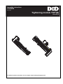
1
Assembly Instructions
P1918E/EN
2011-06
Tightening module TS/TUS
Serie BTS
For additional product information visit our website at http://www.apextoolgroup.com
About the assembly instruction
This assembly instruction is the – translation of the original assembly instruction – and describe how to
remove and install the tightening module in the motor.
Secondary information
P1916E
Assembly instructions DGD-IS built-in nutsetter
P1917E
System handbook m-Pro-400S-DGD-Intelligente-Spindel
P1919E
Assembly instructions Supply module CPS3
P1921E
Service manual DGD-intelligent-spindle
P1792E
Operator information Nutsetter control unit m-Pro-400S
P1779E
System manual nutsetter control unit m-Pro-400S
P1909E
Spare parts sheet Tightening module
P1910E, P1911E, P1912E
Spare parts sheet Attachment
P1913E
Spare parts sheet Gearing
P1914E
Spare parts sheet Motor
P1915K
Spare parts sheet Transducer
Symbols in text
➔
Identifies instructions to be followed.
•
Identifies lists.
Abbreviations
m-Pro-400S(E)
Station controller
m-Pro-400S-CPM…
Nutsetter control unit
TS/TUS
Tightening module
CPS3
Supply module
DGD-ISD
DGD intelligent spindles
Symbols in graphics:
Identifies movement in a direction.
Identifies function and force.
Disclaimer:
Cleco reserves the right to modify, supplement or improve this document or the product without prior notice.
This document may not be reproduced in whole or in part in any way, shape or form, or copied to another
natural or machine-readable language or to a data carrier, whether electronic, mechanical, optical or otherwise, without the express permission of Cleco.
Cleco is a trademark of the Apex Tool Group Division.
2
P1918E/EN 2011-06
18a_Deckblatt en.fm, 15.06.2011
Safety
1
Safety
1.1
Warnings and notes
DANGER!
A symbol combined with the word DANGER warns of an impending health risk or risk of fatal injury to
personnel. If this danger note is not adhered to, severest injury that may lead to the death of people, is
the consequence.
WARNING!
A symbol combined with the word WARNING warns of a potentially dangerous situation for the health
of personnel, which could result in death or serious injury if not avoided.
CAUTION!
A symbol combined with the word CAUTION warns of a potentially harmful situation for the health of
personnel or damage to property or the environment. If this warning is not observed, injuries, property
or environmental damage may occur.
NOTE
This symbol indicates a general instruction.
General instructions include application tips and special useful information, but no warnings against
dangers.
1.2
Basic requirements for safe working practices
Take the fastening system into service only after you have read and completely understood the following
safety instructions and this system manual. Failure to observe the instructions below may result in electric
shock, fire and serious injuries.
DANGER!
High leakage current –
Fatal electric shock could occur!
➔ Always disconnect the power supply before performing maintenance work on the DGD-IS and the
m-Pro-400S-CPM….
➔ Always disconnect the system cable, motor or motor cable from the
m-Pro-400S-CPM… or DGD-IS before making throughput, resistance and short circuit measurements.
➔ Do not attempt to repair possible faults on the fastening system by yourself if you do not have the
required knowledge! Inform the local repair center or your Cleco representative.
WARNING!
High temperature –
the motor on the DGD-IS may heat up and cause burns during removal.
(max. engine temperature 90 °C). Wear gloves.
18b_Sicherheit en.fm, 15.06.2011
P1918E/EN 2011-06
3
1
2
Transport / Storage
1.3
Operator training
•
•
•
•
1.4
The fastening system may only be operated by personnel that have been trained and instructed
correspondingly and authorized by the operator.
The fastening system may only be maintained and serviced by personnel
instructed by qualified staff from Cleco.
The operator must make sure that all new operating and maintenance personnel are instructed in the
operation and maintenance of the fastening system to the same extent and with the same care and
attention.
Personnel who are being trained may work on the fastening system only under the supervision of an
experienced operator.
Personal protective equipment
When working
• Wear the protective goggles to protect against spurting metal splinters.
1.5
Intended use
The owner is responsible for using the machine according to its designated use.
When assembling the tightening module, the following conditions must be fulfilled so that other components
can be attached to the DGD-IS correctly without affecting the safety and health of personnel:
• The tightening module is designed for stationary operation and is intended exclusively for controlling the
DGD-IS. Do not use as a hand-held tool.
• Unauthorized alterations, repairs and modifications are prohibited for reasons of safety and product liability.
• Do not operate the tightening module outdoors.
2
Transport / Storage
•
•
Transport only in the original packing.
If the package is damaged, check the part for visible damage.
Inform the carrier or Cleco if necessary.
System components
TS/TUS
4
Storage temperature
Relative humidity
-20 to 70 °C
0 to 90 % no condensation
P1918E/EN 2011-06
18b_Sicherheit en.fm, 15.06.2011
Attaching TS 961146 to the motor
3
Attaching TS 961146 to the motor
NOTE
Before replacing a component
➔ always carry out a machine capability study (MFU).
After assembly
➔ check the calibration of the torque transducer.
➔ check the function of the angle encoder.
We recommend servicing by Cleco.
➔ Loosen the countersunk screw 1
(ISO 10642, M4).
4
size 2.5
➔ Open the panel 2
➔ Counter the screw (in the housing, not
illustrated) using Allen key 3 size 5.
5
➔ Remove the hex nut 4 (lock nut).
O-ring must remain on the screw 5 !
Do not push the screw 5 into the housing!
Otherwise you will need to remove the
housing.
3
2
1
1.
➔ Place the motor in position.
Click!
➔ Guide the cable into the housing without
damaging. Do not pinch!
➔ Carefully guide the motor into the housing
opening.
When unscrewing and tightening plug
connectors, ensure the following:
➔ Always hold the connector by the
housing, not by the cable!
2.
18c_Montage en.fm, 15.06.2011
P1918E/EN 2011-06
5
3
4
Attaching TUS 961147 to the motor
➔ Tighten the screws.
3.
➔ Tighten the screw 3.
➔ Close the panel 2.
➔ Tighten the countersunk screw 1
(ISO 10642, M4).
3
2
1
4.
4
Attaching TUS 961147 to the motor
➔ Loosen the countersunk screw 1
(ISO 10642, M4).
4
size 2.5
➔ Open the panel 2
➔ Counter the screw (in the housing, not
illustrated) using Allen key 3 size 5.
5
➔ Remove the hex nut 4 (lock nut).
➔ O-ring must remain on the screw 5!
Do not push the screw 5 into the
housing! Otherwise you will need to
remove the housing.
3
2
1
1.
6
P1918E/EN 2011-06
18c_Montage en.fm, 15.06.2011
Attaching TUS 961147 to the motor
➔ Guide the cable through the housing without
damaging.
When unscrewing and tightening plug
connectors, ensure the following:
➔ Always hold the connector by the
housing, not by the cable!
2.
➔ Tighten the screws.
3.
➔ Carefully place the connector in the
housing opening. Do not pinch the cable!
Click!
4.
18c_Montage en.fm, 15.06.2011
P1918E/EN 2011-06
7
4
4
Attaching TUS 961147 to the motor
➔ Tighten the screws.
5.
➔ Tighten the screw 3.
➔ Close the panel 2.
3
➔ Tighten the countersunk screw 1
(ISO 10642, M4).
2
1
5.
8
P1918E/EN 2011-06
18c_Montage en.fm, 15.06.2011
Sales & Service Centers
Note: All locations may not service all products. Please contact the nearest Sales & Service Center for the
appropriate facility to handle your service requirements.
Detroit, MI
Seattle, WA
England
India
Apex Tool Group
Sales & Service Center
2630 Superior Court
Auburn Hills, MI 48326
USA
Phone: +1-248-393-5640
Fax: +1-248-391-6295
Apex Tool Group
Sales & Service Center
2865 152nd Avenue N.E.
Redmond, WA 98052
USA
Phone: +1-425-497-0476
Fax:
+1-425-497-0496
Apex Tool Group GmbH &
Co. OHG
C/O Spline Gaugesl
Piccadilly Tamworth
Staffordshire B78 2ER
United Kingdom
Phone: +44-191 419 7700
Fax:
+44-191 417 9421
Apex Power Tools India
Private Limited
Gala No. 1, Plot No. 5
S. No. 234, 235 & 245
Indialand Global Industrial
Park
Taluka-Mulsi, Phase I
Hinjawadi, Pune 411057
Maharashtra, India
Phone: +91-20-66761111
Houston, TX
York, PA
France
Mexico
Apex Tool Group
Sales & Service Center
6550 West Sam Houston
Parkway North, Suite 200
Houston, TX 77041
USA
Phone: +1-713-849-2364
Fax:
+1-713-849-2047
Apex Tool Group
Sales & Service Center
3990 East Market Street
York, PA 17402
USA
Phone: +1-717-755-2933
Fax:
+1-717-757-5063
Apex Tool Group SNC
25 Rue Maurice Chevalier
BP 28
77831 Ozoir-la-Ferrière
Cedex, France
Phone: +33-1-6443-2200
Fax:
+33-1-6440-1717
Apex Tool Group México
S. de R.L. de C.V.
Vialidad El Pueblito #103
Parque Industrial
76220 Querétaro
Mexico
Phone: +52 (442) 2113800
Fax:
+52 (442) 1030443
Lexington, SC
Brazil
Germany
China
Apex Tool Group
670 Industrial Drive
Lexington, SC 29072
USA
Phone: +1-800-845-5629
Phone: +1-803-951-7544
Fax:
+1-803-358-7681
Apex Tool Group
Sales & Service Center
Caixa Postal 692
18001-970 Sorocaba, SP
Brazil
Phone: +55-15-238-3929
Fax:
+55-15-238-3260
Apex Tool Group
GmbH & Co. OHG
Industriestraße 1
73463 Westhausen
Germany
Phone: +49-7363-81-0
Fax:
+49-7363-81-222
Apex Power Tools Trading (Shanghai) Co., Ltd
A company of
Apex Tool Group, LLC
A8, No.38, Dongsheng
Road, Shanghai,
China 201201
Phone: +86-21-60880320
Fax:
+86-21-60880298
Los Angeles, CA
Canada
Hungary
Apex Tool Group
Sales & Service Center
6881 Stanton Avenue, Unit B
Buena Park, CA 90621
USA
Phone: +1-714-994-1491
Fax:
+1-714-994-9576
Apex Tool Group
Sales & Service Center
7631 Bath Road
Mississauga, Ont. L4T 3T1
Canada
Phone: +1-866-691-6212
Fax:
+1-905-673-4400
Apex Tool Group
Hungaria Kft
Platànfa u. 2
9027 Györ
Hungary
Phone: +36-9666-1383
Fax:
+36-9666-1135
Apex Tool Group GmbH & Co. OHG
Industriestraße 1
73463 Westhausen
Germany
Phone: +49-7363-81-0
Fax: +49-7363-81-222
www.apexpowertools.eu