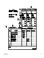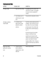
1
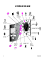
GB English ........................................ 2 E Español ...................................................................... 29 F Français ...................................................................... 57 EC CONTROLLER ICON LEGEND + TEST PRESET SCHEDULES OFF AUTO DATE/TIME DAY CYCLE SET MONTH WATER DAY PROGRAM START TIME SET DAY STATION RUN TIME SET TIME WATER BUDGET - 2 PROGRAM BUTTON ENTER MANUAL CYCLE MANUAL STATION(S) Ec Controller CONTENTS Introduction ........................................................... 4 Ec Controller ................................................................. 4 Controller Stations ......................................................... 5 What Is a Program? ........................................................ 5 Controller Basics .................................................... 6 Programming Under Battery Power .................................. 6 Installing the Battery ...................................................... 6 Diagnostic Circuit Breaker .............................................. 6 Controls and Indicators ................................................. 7 Programming Checklist ................................................. 8 Controller Programming Chart ........................................ 8 Programming the Controller ................................. 12 Erase Any Existing Programming .................................. 12 Set Year ...................................................................... 12 Set Month and Day ...................................................... 12 Set Time ..................................................................... 13 Select Pre-Set Schedules ............................................ 13 Select Program (A, B, and/or C) ................................... 14 Set Watering Day Cycle ................................................ 14 Ec Controller Set Watering Days ....................................................... 15 Set Program Start Time(s) ............................................ 16 Delete Program Start Time(s) ........................................ 16 Set Station Run Times ................................................. 17 Operating the Controller ....................................... 17 Off Mode ..................................................................... 17 Auto Mode .................................................................. 18 Adjust Water Budget .................................................... 18 Manually Run Stations and Programs ........................... 19 Run a Test Program ...................................................... 20 Installing the Controller ........................................ 21 Choose a Proper Location ............................................ 21 Mount the Controller .................................................... 22 Connect Main Power Wires ........................................... 22 Connect Field Wires to Remote Control Valves .............. 22 Troubleshooting ................................................... 24 Have a question, problem, or comment? In the United States, call Rain Bird Technical Assistance at 800-247-3782. Outside the United States, call your Rain Bird dealer. © 2000 Rain Bird Sprinkler Mfg. Corp. ® Registered trademark of Rain Bird Sprinkler Mfg. Corp. 3 WARNING: A CIRCUIT BREAKER OR CUTOFF SWITCH IS TO BE PROVIDED IN THE FIXED WIRING TO ISOLATE THE CONTROLLER. INTRODUCTION MEMORY IS RETAINED BY A BATTERY WHICH IS TO BE DISPOSED OF IN ACCORDANCE WITH LOCAL REGULATIONS. Thank you for purchasing a Rain Bird Ec irrigation system controller. This manual shows how to install, program, and operate your controller. Please read these instructions carefully and keep this manual in a handy place for future reference. CAUTION ICONS The lightning flash with arrowhead symbol, within an equilateral triangle, is intended to alert the user to the presence of uninsulated dangerous voltage within the products enclosure that may be of sufficient magnitude to constitute a risk of electronic shock to persons. The exclamation point within an equilateral triangle is intended to alert the user to the presence of important operating and maintenance (servicing) instructions in the literature accompanying the product. Ec Controller The Rain Bird Ec is a compact, easy-to-use controller that offers the following features: • Three programs, with independent watering days • Up to four watering start times per program • Option to set any day of the week as a watering day • Water budgeting feature across all programs • Battery backup to retain time, date, and programming CERTIFICATE OF CONFORMITY TO EUROPEAN DIRECTIVES Rain Bird declares that the Ec device, an irrigation controller, conforms to the 72/23/CEE European Directives for electrical safety and to 89/336/CEE and 93/31/CEE concerning electromagnetic compatibility. The applicable standards in accordance with the technical file are : EN 60065 for electrical safety. EN 50081-1 ed 92 for interference. EN 50082-1 ed 92 for interference resistance. The Ec type device is powered by 230V~,50Hz, single phase. 4 during power outages • Three year warranty Ec Controller Controller Stations DIAGRAM 1 The Rain Bird Ec controller is an electronic timer that controls when your sprinkler system turns on, and how long the sprinklers run. Depending on the model, the Ec can control four, six, or nine watering stations. A station is a series of sprinklers, or other irrigation devices, connected to a common remote control valve. When the valve receives a signal from the controller, the valve opens and turns on the sprinklers connected to it. You will need to understand the following terms to successfully program your Ec controller. • Watering day cycle The period of days in which the controller repeats the program you set. For example, a 7-day cycle is a weekly schedule that repeats once every seven days. A 2-day cycle repeats every other day. • Watering days The specific days within the watering day cycle when watering takes place. In a 7-day cycle, you may select multiple watering days within the cycle. For example, you might water on day 1 (Monday), day 3 (Wednesday), and day 5 (Friday). In a 1- through 6-day cycle, day 1 is always the only watering day. A 2-day cycle waters on day 1, skips a day, and then waters again on day 1 as the cycle repeats. A 3-day cycle waters on day 1, skips 2 days, and then repeats. This illustration shows a diagram of a station layout. Station 1 is currently watering. When station 1 finishes, the controller shuts it off and turns on station 2. When station 2 finishes watering, station 3 begins, and so on. What Is a Program? Programming is the process of telling the controller exactly when and how long you want to water. The controller opens and closes the remote control valves for each station according to the program you set. The Ec offers three independent programs; A, B, and C. Each program controls from one to six stations, and lets you customize your watering schedules to meet the needs of different types of plants, soil conditions, slopes, shady or sunny areas, etc. Ec Controller • Start time This is the time, or times, the first station in a program begins watering. All other stations in the program then follow in sequence. • NOTE: The term start time refers to the time the program begins not the time each individual station begins to run. Run time The number of minutes that each station runs. 5 CONTROLLER BASICS NOTE: Make sure the controller is connected to an AC power supply when replacing the battery, or you will lose all programming information including date and time. Programming Under Battery Power If you wish, you can program the controller under battery power. This feature can be useful if the controller is installed in an area that is not readily accessible. This feature also allows you to enter program information before installing the controller at a job site. To program the Ec controller under battery power, you must first install the battery. NOTE: To save battery power, the Ec goes into Sleep mode after 40 seconds of inactivity on the programming dial or buttons. Press any button once to reactivate the controller. Installing the Battery DIAGRAM 2 The battery back-up feature retains time, date, and programming information during power outages. The battery also lets you program the controller under battery power before it is connected to an AC power supply. For best results, use a long-life, 9-Volt alkaline battery. A new battery will normally provide power for up to one year. Replace the battery yearly to ensure an uninterrupted power supply. 6 To install the battery: 1. Remove the controllers lower access cover to expose the battery compartment. 2. Snap the two-wire battery clip onto the terminals of the new battery. If you are replacing an old battery, dispose of the old battery properly. 3. Insert the new battery snugly into the battery compartment. 4. Replace the lower access cover. Diagnostic Circuit Breaker DIAGRAM 3 If the Ec controller detects an electrical short circuit on one of the sprinkler systems station wires or valve solenoids, the controller automatically shuts off the station with the fault. After 30 to 40 seconds, while it checks again to confirm the fault, the controller advances to the next working station in the program. Ec Controller Every three seconds, the LCD displays the problem stations number and the letters Err. The controller will continue to run each operable station in the program. As each station is running, the controller (at an alternate 3-second interval) displays the working stations number and run time remaining. When the controller finishes the program, it will continue to display the problem stations number and the Err message. After the program finishes, you should isolate and repair the short circuit. Short circuits occur most frequently in the valve solenoid (the plastic-encapsulated coil on the valve with the two wire leads), or in the wire connectors to the valve leads. After you find and repair the short circuit, turn the programming dial to AUTO. Then press ENTER to clear the Err message from the display. You may wish to operate the station manually to make sure it works properly. (See Manually Run a Station(s) on p. 19). The LCD display shown in Diagram 3 indicates that the controller has detected a short circuit on station 2. Ec Controller Controls and Indicators DIAGRAM 4 This illustration shows the programming controls on the face of the Ec controller. These controls include: 1. Liquid Crystal Display (LCD) During normal operation, displays the time of day and the programs that will run today. During programming, shows the results of your commands. During watering, shows the station that is running, the minutes remaining in the stations run time, and whether another program is waiting to water. 2. + and - buttons Set start times and days, and make programming changes. 3. Programming dial Turns the controller to OFF or AUTO modes, and selects other programming functions. 4. PROGRAM button Selects watering programs A, B, or C. 5. ENTER button Enters programming commands, and starts manual operation. 7 Programming Checklist To program your Ec controller for the first time, we recommend that you complete the steps in the order listed to the right. ❒ Fill out the Programming Chart ....................... p. 8 ❒ Erase any existing programming ..................... p. 12 ❒ Set the current year/month/day/time ............... p. 12 For each program: A B C ❒ ❒ ❒ Select pre-set schedules .................. p. 13 ❒ ❒ ❒ Select program (A, B and/or C) ......... p. 14 ❒ ❒ ❒ Set the watering day cycle ................ p. 14 ❒ ❒ ❒ Set the watering days ........................ p. 15 ❒ ❒ ❒ Set the program start time(s) ............. p. 16 ❒ ❒ ❒ Set the station run time(s) ................ p. 17 ❒ Set the controller to automatic operation ........... p. 18 For your convenience, a check-off box (❐) is provided for each step. 8 Controller Programming Chart Before programming your Ec controller, fill out the Programming Chart included with your controller. Then program the controller in the order shown on the Programming Checklist. 1. Select the watering day cycle you wish to use, and circle the watering days within the cycle. In the example shown for program A, the operator has chosen a 7-day watering cycle and circled M, W, and F as watering days. This means that program A will water every Monday, Wednesday, and Friday. NOTE: If you plan to use only one program for your watering needs, select program A. 2. For program B, the operator selected a 3-day watering cycle. With these selections, program B will water once, skip two days, and then water again on the first day of a new three day cycle. 3. You may also choose three special watering day cycles that do not require you to select watering days. These cycles are: • Ev = Waters only on even-numbered days of the month. • Od = Waters only on odd-numbered days of the month. Ec Controller Ec Controller 9 • Od31 = Waters only on odd-numbered days of the month, but not on the 31st of any month or on February 29. (This watering day cycle complies with special ordinances in some water-restricted areas). 4. In the Program Start Times box for program A, write the time you want the program to begin watering. You may assign up to four start times to each program. If you want the program to water only once each watering day, enter only one start time. Enter other start times only if you want to repeat the entire program more than once each watering day. 7. In the Run Time column for each program, enter the number of minutes you want each station to run. Notice that stations 1 through 4 are assigned to program A, while stations 5 and 6 are assigned to program B. The Ec allows you to use the same station in multiple programs for special watering needs. However, for most applications, choosing not to repeat a station makes programming simpler. NOTE: Any Water Budget setting applies to all programs (A, B, and C). 5. Enter the start time(s) for program B (if any). In the example, Program A begins watering at 7 a.m. Program B begins watering twice each watering day, once at 5 a.m. (05:00) and again at 3 p.m. (15:00) NOTE: If the total run time for one program overlaps the start time for a second program, the controller will automatically stack the programs and delay the start time of the second program until the first program finishes watering. 6. Next to each station number, enter a brief description of the area covered by each controller station. Remember, a station is a set of sprinklers operated by one remote control valve. 10 Ec Controller Ec Controller 11 PROGRAMMING THE CONTROLLER Set Year Erase Any Existing Programming 1. Turn the programming dial to the DATE/TIME position. DIAGRAM 5 After you finish filling out the Programming Chart, you are ready to begin programming the controller. When you program the controller for the first time, it is a good idea to use the Program Erase feature to erase any existing programming which may be in the controllers memory. You may also use Program Erase any time you want to erase all programming and start from scratch. 1. Remove the controllers lower access cover. 2. Locate the small recessed compartment on the right side of the controllers front panel. To erase all programming, reach into this compartment with a small flathead screwdriver and momentarily connect the two small silver contacts in the bottom of the recess. 3. When the display goes blank, remove the screwdriver from the contacts. The time AM 12:00(00:00 in 230V versions) will blink in the display. All previous programming is now erased, and you may turn the programming dial to the DATE/TIME position and begin setting the Year, Month, Day, and Time. 12 DIAGRAM 6 2. The figure 1998 appears in the display window. 3. Press + or - to set the current year (between 1998 and 2098). 4. Press ENTER. NOTE: The Ec is year-2000 compliant and will maintain the proper calendar through the year 2098. Set Month and Day DIAGRAM 7 1. After setting the correct year, leave the programming dial on DATE/TIME. 2. The month and day appear as 01 01, with the first 01 flashing (representing the month). A cursor will appear under the SET MONTH icon. 3. Press + or - to set the current month (1 through 12). Ec Controller NOTE: In 230 V models, the first flashing 01 represents the day. You will set the day first, and then the current month. 4. Press ENTER. 5. The second 01 begins flashing (representing the day of the month). A cursor will appear under the SET DAY icon. 6. Press + or - to set the current day (1 through 31). 7. Press ENTER. Set Time DIAGRAM 8 1. After setting the correct month and date, leave the programming dial on DATE/TIME. 2. The time of day appears. In 117 Volt models, the display will show AM or PM (for example, 12:01 AM). In 230 Volt models, the time appears in 24-hour format, (for example 14:01), and the display will not show AM or PM. A cursor will appear under the SET TIME icon. 3. Press + or - to set the current hour (1 through 12 AM or PM, or 00:00 through 23:00). Ec Controller 4. Press ENTER. 5. The minute digits begin flashing. 6. Press + or - to set the current minute (1 through 59). 7. Press ENTER. Select Pre-Set Schedules DIAGRAM 9 Use this procedure if you want to select a pre-set schedule. If you want to set your own custom watering schedule, go directly to Select Program (A, B, and/or C). For your convenience, the Ec has three pre-set watering schedules you can select on any program (A, B, or C). • 5 Pr E1 Waters all stations for five minutes every day at 6 a.m. (06:00), 10 a.m. (10:00), and 2 p.m. (14:00). • 10 Pr E2 Waters all stations for ten minutes every other day at 6 a.m. (06:00). • 10 Pr E3 Waters all stations for ten minutes every third day at 6 a.m. (06:00). 13 1. Turn the programming dial to PRESET SCHEDULES. 2. The first pre-set schedule (5 Pr E1) appears in the display. 3. To select one of the other pre-set schedules, press + or until the desired schedule appears in the display. 4. Press the PROGRAM button until the desired program letter (A, B, or C) appears in the display with the pre-set schedule. 5. Then press ENTER. The program letter flashes to confirm your selection. After selecting a pre-set schedule, you can modify the program settings (watering day, start time, etc.) by using the programming steps given on the following pages. If you modify a pre-set schedule, you will not see Blank or Default settings as described throughout the manual. 6. After setting the desired preset schedule, turn the programming dial back to AUTO. Select Program (A, B, and/or C) DIAGRAM 10 1. Turn the programming dial to DAY CYCLE. 2. The letter of the currently selected program (A, B, or C) appears in the display. 3. Press the PROGRAM button until the desired program (A, B, or C) appears in the display. Remember, if you plan to use only one program, use program A. NOTE: It is easier to select one program (A, B, or C) and program it completely before moving on to the next program. Switching from program to program can be confusing. Set Watering Day Cycle DIAGRAM 11 1. Make sure the programming dial is on DAY CYCLE. 2. Press + or - until the watering day cycle you want to use appears in the display along with the selected program (A, B, or C). Available watering day cycles include: • 1 through 6 Waters once every one to six days. 14 Ec Controller • 7-day (Custom) Waters on a weekly cycle; any day of the week can be a watering day. • Ev Waters only on even-numbered days. • Od Waters only on odd-numbered days. • Od31 Waters only on odd-numbered days, except the 31st of any month and February 29th. 3. If you select a 7-day, or a 1- through 6-day watering cycle, go to Set Watering Days. NOTE: If you select Ev, Od, or Od31 as your watering day cycle, you do not have to set watering days. Go directly to Set Program Start Time(s) on p. 16. Set Watering Days DIAGRAM 12 Use the procedures below to set watering days for a 7-day, or a 1- through 6-day watering cycle. 7-Day Watering Cycle 1. Turn the programming dial to WATER DAY. Ec Controller 2. If you selected a 7-day watering cycle, the seven weekdays appear as a row of numbers and the number 1 in the day cycle flashes. 3. The display shows the programs letter (A, B, or C). 4. A number appears, indicating the today number. The days abbreviation also appears in the display. 5. Press + or - to turn a particular watering day ON or OFF. An ON day has a box around it. An OFF day has no box around it. 6. Press ENTER to move to the next day. 7. Repeat steps 5 through 7 for each day. 1- to 6-Day Watering Cycle DIAGRAM 13 1. Turn the programming dial to WATER DAY. 2. If you selected a 1- to 6-day watering cycle, the row of days in that cycle appears in the display with a box around day 1. The only watering day in a 1- to 6-day cycle is day 1. 3. The display shows the programs letter (A, B, or C). 4. A flashing number appears in the display, indicating where today is in the watering cycle. 15 5. Press + or - to move todays position in the watering cycle. Set Program Start Time(s) DIAGRAM 14 1. Turn the programming dial to PRGM START TIME. 2. The program letter (A, B, or C), the number 1 (indicating the earliest start time), and a row of four dashes ... appear in the display. 3. Press + or - to set the program start time. A program can begin watering at any minute of the day or night. If you want all the stations on the program to run only once each watering day, enter only one start time for the program. 4. To enter another start time, press ENTER. The next start time number (2, 3, or 4) and the row of four dashes appear in the display. Repeat steps 3 and 4 to set up to four separate start times for each program, if needed. NOTE: If you selected one of the pre-set schedules, you will see the default start time(s) for that schedule. Delete Program Start Time(s) DIAGRAM 15 1. If you want to delete an unwanted start time from a program, turn the programming dial to PRGM START TIME. 2. Press ENTER to select the start time number (1, 2, 3, or 4) you want to delete. NOTE: Start times appear in chronological order. The earliest start time is number 1, the next later start time is number 2, and so on. If you delete a start time, all later start times are automatically advanced by one start time number. This renumbering only occurs after you move the programming dial from the PRGM START TIME position to another function. 3. The start time number to be deleted appears in the display. 4. Press + or - until the blank position (four dashes, ...) appears in the display. The blank position is located between 11:59 p.m. (23:59) and 12:00 a.m. (00:00). 5. Turn the programming dial back to the AUTO position. The unwanted start time is now deleted. 16 Ec Controller Set Station Run Times DIAGRAM 16 1. Turn the programming dial to STATION RUN TIME. 2. The program letter (A, B, or C), the number 1 (indicating the station number), and 0 00 appear in the display. 3. Press + or - to set the run time for station number 1. You can set a station to run from 0 minutes up to 240 minutes (four hours), in one-minute increments. All run times display in minutes (for example, a two hour run time will appear as 120 minutes). NOTE: If you do not want to include a particular station in the selected program, set that stations run time to zero (0 00). 4. Press ENTER to display additional stations. Repeat steps 3 and 4 to set a run time for each station. You have now completed all programming steps for one program. If you are finished programming, turn the programming dial to the AUTO position to run all programs automatically. If you want to enter settings for another program, repeat the programming instructions, beginning with Select Program (A, B, and/or C) on p. 14. Ec Controller OPERATING THE CONTROLLER After programming the controller, you will normally set it to AUTO mode to operate all programs automatically. You can manually run one or more programs, or manually run a single station or several stations. In addition, you can adjust the Water Budget to increase or decrease the run time of all programs by a selected percentage (in 10% increments). You may also wish to run a test program to make sure all sprinklers in the system operate properly. Off Mode DIAGRAM 17 1. To turn the controller off and suspend all watering, turn the programming dial to OFF. 2. In the OFF position, the LCD displays OFF. The controller remembers the current time and date and retains all programming, but no watering occurs. You may wish to turn the controller off during a rainy period, or for any day(s) when you do not want watering programs to run as scheduled. 17 Auto Mode DIAGRAM 18 & 19 1. To return the controller to automatic operation, turn the programming dial to AUTO. 2. When the controller is NOT watering, it displays: • Any program (A, B, C, or none) scheduled to water today • The current time • %A %B %C, if there is a water budget setting other than 100% 3. When the controller IS watering, it displays: • The program that is running • The station number currently running • The watering time remaining for that station • %A %B %C, if there is a water budget setting other than 100% 18 Adjust Water Budget DIAGRAM 20 & 21 Adjusting the Water Budget feature is the easiest way to increase or decrease the run times of all stations on a program. You can use Water Budget to decrease watering during cool winter months, or to increase watering during hot, dry periods. You can set the Water Budget percentage from 10% to 200% (all station run times doubled), in increments of 10%. Changing the Water Budget percentage affects all stations on all three programs (A, B, and C). Water Budget percentages are calculated on the normal programmed run time for each station. For example, if a station is programmed to run for 10 minutes, and you set the Water Budget to 80%, the station will only run for 8 minutes (80% of 10 minutes). If you set the Water Budget to 120%, that same station will run for 12 minutes (120% of 10 minutes). NOTE: Water Budget will not split a minute. One whole minute is the lowest run time allowed. 1. Turn the programming dial to WATER BUDGET. 2. The number 100 appears in the display. This indicates that all stations are running at 100% of their programmed watering time. Ec Controller 3. Press + to increase the Water Budget percentage, or press to decrease the Water Budget percentage. 4. When the Water Budget percentage is set to any figure other than 100, all programs (A, B, and C) display a percent sign (%) in front of the program letter. 5. After setting the Water Budget percentage, turn the programming dial back to AUTO. All station run times will be increased or decreased by the selected Water Budget percentage. Manually Run Stations and Programs DIAGRAM 22 & 23 You can manually run individual stations if you think a particular area needs additional watering. You can also run an entire program manually. Each station assigned to the program will run for its allotted time. Manually Run a Station(s) 1. Turn the programming dial to MANUAL STATION. 2. The number 1 followed by 0 00 appears in the display. This means that station number 1 is set for zero manual run time. Ec Controller 3. If you want to manually run a station other than number 1, press ENTER until the desired station number appears in the display. 4. If you want to manually run the displayed station, press + or - to set the stations manual run time (from one minute to four hours). 5. Press ENTER to begin watering. NOTE: You can stack higher numbered stations to operate manually by pressing ENTER after setting the run time for each station. Stacked stations will run in consecutive order, even if they are stacked in a different order (i.e., a lower numbered station will not run if it is stacked after a higher numbered station). 6. After setting the manual run time for all stations desired, turn the programming dial back to AUTO. The number of the first manually operated station appears in the display, along with its remaining run time. You can press ENTER to manually advance to the next station When manual operation finishes, the controller returns to AUTO mode and awaits the next scheduled program start time. 19 Manually Run a Program DIAGRAM 24 1. Turn the programming dial to MANUAL CYCLE. 2. Program A appears in the display. NOTE: Water budgeting does apply to manually operated programs. After the last manual program runs, the controller returns to AUTO mode and awaits the next scheduled program start time. 3. To choose another program, press the PROGRAM button (ABC) until the desired program letter appears in the display. NOTES: Manually operating a station does not affect the stations run time(s) in the automatic programs (A, B, or C). 4. Press ENTER to start the selected program. Manual operation cancels the operation of any automatic program in progress. Also, Water Budgeting does not affect manually operated stations. NOTES: You can stack two or three programs to operate manually by pressing ENTER after selecting each program. The controller runs stacked programs in order (A, then B, then C), no matter in which order you stack them. For example, if you start program B, then stack program C, then program A, the controller will finish B, and then run A, and finally C. 5. Turn the programming dial back to AUTO. The letter of the manually operating program (A, B, or C) appears in the display. Any stacked programs flash until their turn to run. 20 Run a Test Program DIAGRAM 25 The controllers built-in test program will run each station that has a non-zero watering time. When you run the test program, the controller operates each station in numerical sequence, from lowest to highest. You can use this feature to check the operation of all sprinklers in the system. 1. To test all controller stations, turn the programming dial to TEST. Ec Controller NOTE: If you want to test only one (or more) stations, follow the procedure in Manually Run a Station(s) on p. 19. 2. The number 2 appears in the display, representing a twominute test run per station. 3. Press + or - to increase or decrease the test run time. You can set the test run time anywhere between 1 and 10 minutes. Each station will run for the time you set here. 4. Press ENTER to start the all-stations test. 5. Then turn the programming dial back to the AUTO position. During the test, the number of each operating station appears in the display, along with the stations remaining run time. Any station set for zero run time in all of the automatic programs (A, B, or C) will be skipped in the all-stations test. NOTE: At any time during the all-stations test, you can press ENTER to manually advance to the next station. When the all-stations test is complete, the controller returns to AUTO mode and awaits the next scheduled program start time. Ec Controller INSTALLING THE CONTROLLER Although this manual provides directions for connecting the wiring to the controller, local electrical codes may vary in their requirements for proper and safe installation. NOTE: This controller must be installed in full compliance with local electrical codes. The Ec controller must be installed indoors only. Choose a Proper Location Choose a secure location where you can easily reach the controller. We recommend mounting the controller at eye level in a utility room (garage, laundry room, etc.). 1. The mounting location must be within 5 feet (1,5m) of the electrical wall outlet. NOTE: To minimize electrical interference, select a location at least 15 feet (4,6 m) away from highdraw motors such as air conditioners, refrigerators, or pool pumps. 2. When selecting a location, choose a flat, stable vertical surface to mount the controller on. Allow enough clearance for electrical conduit and connections at the bottom of the controller case. 21 Mount the Controller DIAGRAM 26 1. Hold the provided template against the wall in the desired mounting location. Use a pencil to mark the location of the three holes for the mounting fasteners, as shown on the template. 2. Use a nail to tap a small pilot hole on each pencil mark for the mounting fasteners. Using the mounting fasteners provided, drive the top two fasteners into the wall. 3. Use the keyhole-shaped slots on the back of the controller to hang the controller on the two mounting fasteners. Make sure the shafts of the fasteners are well up into the narrow part of the keyhole slot. 4. Remove the lower access cover and drive the third mounting fastener through the hole in the controllers lower access panel. Connect Main Power Wires DIAGRAM 27 The Ec controller has an external transformer that reduces standard supply voltage to 24 VAC to operate the remote valves connected to the controller. 22 CAUTION: To avoid electrical shock, DO NOT plug in the transformer until you have connected it to the controller. To connect the transformer cable to the terminal strip in the controller cabinet: 1. Make sure the transformer is NOT plugged in. 2. Plug the snap-on connector on the transformer cable into the 24VAC connection point on the controller terminal strip. 3. Plug the transformer into any standard, three-prong 117 VAC grounded wall plug. For 230V versions, attach an appropriate plug and plug in the transformer to a 230VAC power source. Connect Field Wires to Remote Control Valves DIAGRAM 28 The wires coming back to the controller from the electric valves in the field can be routed into the controller through the hole in the bottom of the cabinet. Ec Controller This illustration shows the various wire runs and connections between the controller and the other devices. Each valve should have its own, separate power wire. Use only wire that is codeapproved for underground, low-voltage purposes. 5. That completes the mounting and wiring procedures for your Ec controller. Replace the lower access cover on the controller, and you are ready to begin programming. Refer to Programming the Controller on p. 12. 1. Connect one end of the power wire to a numbered station terminal on the controllers terminal strip. Connect the other end of the power wire to one of the wire leads on the valve solenoid. The wire connectors at the valves must be waterproof. 2. Connect the valve common wire to the COM terminal on the terminal strip. Route the common wire out to the furthest valve, and connect the valve common wire to the remaining wire lead on each valve. 3. If your system includes a master valve on its main line supply, or a 24-volt pump start relay (for activating a pump during irrigation), connect a wire from the device to the MV terminal on the controller terminal strip. 4. Connect the other wire lead on the device to the valve common wire. NOTE: The controller does not provide the main power for a pump. Ec Controller 23 TROUBLESHOOTING SYMPTOM POSSIBLE CAUSE CORRECTION LCD display is blank. 1. Power is off to the controller. Re-establish power to the controller. If the current time is not shown, or your program is no longer in memory, reprogram the controller. 2. If under battery power, the controller may be in sleep mode. Press any button to reactivate the controller. 3. An electrical surge or lightning strike may have affected the controllers electronics. Turn off the controller and disconnect the 9Volt battery. Let the controller sit for two or three minutes. Then reconnect the battery and restore power to the controller. Reset the date and time as described beginning on p. 12. LCD display is partially or completely blank. If the electrical surge did no permanent damage, the controller will accept programm ing commands and function normally. If the controller does not operate properly, contact Rain Bird Technical Assistance at 800-247-3782. In Europe, or outside the United Staes call your Rain Bird dealer. Display shows a station operating, but no watering occurs. 24 4. The valve may have a defective diaphragm, a clogged pilot port, or other malfunction. Check and repair the valve. Ec Controller SYMPTOM POSSIBLE CAUSE CORRECTION Program does not begin watering as scheduled. 5. Programming dial is set to the OFF position. Set the programming dial to AUTO. 6. Start time has not been properly entered for the program. Turn the dial to PRGM START TIME and check the start times entered for the program. If the start time is missing or incorrect, enter it as described on p. 16. 7. Today may not be set as a watering day for the program. If today is a watering day for a program, the program letter appears in the display. Turn the dial to WATER DAY to check the watering days for the program. If necessary, set watering days as described on p. 15. 8. Water supply may be shut off. Make sure water supply line has pressure. 9. No run time has been set for the station. Turn the programming dial to STATION RUN TIME to check the run times set for the station. To add a run time, see p. 17. A particular station does not come on as scheduled. 10. A short circuit in the solenoid or valve wiring has disabled the station. Ec Controller Identify and repair the fault in the electrical circuit. 25 SYMPTOM POSSIBLE CAUSE CORRECTION 11. A start time has not been entered for the stations assigned program. Turn the dial to PRGM START TIME and check the start times entered for the program. If the stations start time is missing, enter it as described on p.16. Watering starts when it should not. 12. An unwanted program start time may have been entered. Turn the dial to PRGM START TIME and check to see if any programs have an unwanted start time. See the instructions beginning on p. 16 for setting and deleting start times. Watering does not stop as scheduled. 13. Programs may have accidentally been set to overlap. Check to see if another programs start time began during the previous programs run cycle. The overlapped program would immediately follow the earlier one. Reprogram if necessary. 14. A valve is stuck in the open position. Turn the programming dial to OFF and wait 10-20 seconds. If the irrigation does not stop, shut off the valve manually and repair the valve. 26 Ec Controller SYMPTOM POSSIBLE CAUSE LCD display shows Err. 15. The automatic circuit breaker has detected an electrical problem. CORRECTION The Err in the display indicates a short circuit or electrical overload on a particular station. The stations number should also be displayed. For example, 2 Err means the problem is in the circuit for Station 2. Usually, the short circuit is in the solenoid on the electric valve, but shorts can also occur in the wire connectors at the valve. Occasionally, nicked or skinned field wires can cause a short. A large pump start relay can also produce a momentary overload that may be detected by the controller. Locate and repair the cause of the short circuit. See Diagnostic Circuit Breaker on p. 6 for instructions on clearing the problem indicator from the display and testing the station. LCD display shows Err for a few seconds and then shows the station operating for a few seconds. Ec Controller 16. Same as Cause #15. See correction for Cause #15. 27 Notes 28 Ec Controller