1
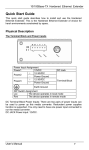
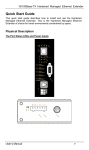
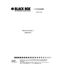
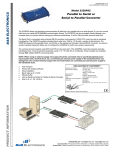
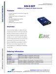
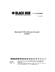
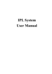
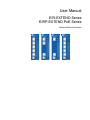
User Manual EIR-EXTEND Series EIRP-EXTEND PoE Series Hardened Ethernet Extender EIR-EXTEND and EIRP-EXTEND Series Documentation Number: EIR-EIRP-EXTENDseries-4612m International Headquarters: 707 Dayton Road Ottawa, IL 61350 USA Phone (815) 433-5100 Website: www.bb-elec.com Sales e-mail: [email protected] Technical Support: [email protected] European Headquarters B&B Electronics Westlink Commercial Park Oranmore, Co. Galway, Ireland Phone +353 91-792444 Website: www.bb-europe.com Sales e-mail: [email protected] Technical Support: [email protected] Original – March 2011 ©2011 No part of this publication may be reproduced or transmitted in any form or by any means, electronic or mechanical, including photography, recording, or any information storage and retrieval system without written consent. Information in this manual is subject to change without notice, and does not represent a commitment on the part. B&B Electronics Manufacturing shall not be liable for incidental or consequential damages resulting from the furnishing, performance, or use of this manual. All brand names used in this manual are the registered trademarks of their respective owners. The use of trademarks or other designations in this publication is for reference purposes only and does not constitute an endorsement by the trademark holder. Table of Contents PREFACE ............................................................................................................................... 1 INTRODUCTION ..................................................................................................................... 1 Product Overview ................................................................................................................................................................... 1 Product Features .................................................................................................................................................................... 1 Packing List ............................................................................................................................................................................ 2 ONE-CHANNEL HARDENED ETHERNET EXTENDER ........................................................ 2 Ports......................................................................................................................................................................................... 2 Ethernet Extender Mode Settings ......................................................................................................................................... 2 DIP switch ............................................................................................................................................................................... 2 Front Panel & LEDs............................................................................................................................................................... 2 LED Indicators ..................................................................................................................................................................... 2 10/100Base-TX and Ethernet Extender Connectors ............................................................................................................. 3 INSTALLATION ...................................................................................................................... 3 Selecting a Site for the Equipment ........................................................................................................................................ 3 Wiring Diagram...................................................................................................................................................................... 4 DIN Rail Mounting................................................................................................................................................................. 4 Connecting to Power .............................................................................................................................................................. 5 Redundant DC Terminal Block Power Inputs ...................................................................................................................... 5 48VDC DC Jack ................................................................................................................................................................... 5 SPECIFICATIONS .................................................................................................................. 6 Manual Documentation Number: EIR/EIRP-EXTENDseries-4612m B&B Electronics Mfg Co Inc – 707 Dayton Rd - PO Box 1040 - Ottawa IL 61350 - Ph 815-433-5100 - Fax 815-433-5104 – www.bb-elec.com B&B Electronics – Westlink Commercial Park – Oranmore, Galway, Ireland – Ph +353 91-792444 – Fax +353 91-792445 – www.bb-europe.com i Preface This manual describes how to install and use the Hardened Ethernet Extender. The Hardened Ethernet Extender introduced here provides one channel for Ethernet over existing voice grade copper wire. The Hardened Ethernet Extender fully complies with IEEE802.3 10Base-T and IEEE802.3u 100Base-TX/FX standards. In this manual, you will find: Product overview Features on the Hardened Ethernet Extender Illustrative LED functions Installation instructions Specifications Introduction The Hardened Ethernet Extender provides one channel for Ethernet over existing voice grade copper wire. This Hardened Ethernet Extender solution is perfectly fitted in the industrial applications or rugged environment. Product Overview Product Features Meets NEMA TS1/TS2 Environmental requirements: temperature, shock, and vibration for traffic control equipment. Meets EN61000-6-2 & EN61000-6-4 EMC Generic Standard Immunity for industrial environment. Operates transparent to higher layer protocols such as TCP/IP. Ethernet port: Supports IEEE802.3/802.3u/802.3x. Auto-negotiation: 10/100Mbps, full/half-duplex; Auto MDI/MDIX. Complies with IEEE802.3at standard for high power input required device and also compatible with IEEE802.3af powered devices (Only available for Hardened IEEE802.3at PoE PSE Ethernet Extender version). Ethernet Extender port (RJ-11 & Terminal Block): Symmetrical on the VDSL, full-duplex 50Mbps communications link over existing copper telephone line. One DIP switch for configuring Local (Loc) and Remote (Rmt). Ten speeds with speed indicator LEDs on front panel of unit, up to 50Mbps @ about 300 meters (984 ft.), down to 1Mbps @ about 1,900 meters (6,232 ft.). 4-port 10/100Base-TX (2-port IEEE802.3at PoE PSE) Ethernet Extender: 2.88A @ 24VDC, 1.44A @ 48VDC. Power consumption: 69.12W Max. 2-port IEEE802.3at PoE PSE Ethernet Extender: 2.88A @ 24VDC, 1.44A @ 48VDC. Power consumption: 69.12W Max. 1-port IEEE802.3at PoE PSE Ethernet Extender: 1.6A @ 24VDC, 0.8A @ 48VDC. Power consumption: 38.4W Max. 4-port 10/100Base-TX Ethernet Extender: 0.36A @ 24VDC, 0.18A @ 48VDC. Power consumption: 8.64W Max. Power Supply: Redundant 24-48VDC Terminal Block power inputs and 48VDC DC JACK with 100-240VAC external power supply. Field Wiring Terminal Markings: Use Copper Conductors Only, 60/75℃, wire range 12-24 AWG, torque value 7 lb-in. Operating temperature range @ -40℃ to 75℃ (-40℉ to 167℉). Tested for functional operation @ -40℃ to 85℃ (-40℉ to 185℉). UL508 Industrial Control Equipment certified Maximum Surrounding Air Temperature @ 75℃ (167℉). For use in Pollution Degree 2 Environment. Supports Din-Rail, Panel, and Rack Mounting installation. Manual Documentation Number: EIR/EIRP-EXTENDseries-4612m B&B Electronics Mfg Co Inc – 707 Dayton Rd - PO Box 1040 - Ottawa IL 61350 - Ph 815-433-5100 - Fax 815-433-5104 – www.bb-elec.com B&B Electronics – Westlink Commercial Park – Oranmore, Galway, Ireland – Ph +353 91-792444 – Fax +353 91-792445 – www.bb-europe.com 1 Packing List When you unpack this product package, you will find the items listed below. Please inspect the contents, and report any apparent damage or missing items immediately to our authorized reseller. The Hardened Ethernet Extender CD with user’s Manual Quick Start Guide AC to DC Power Adaptor and Power Cable (optional) One-Channel Hardened Ethernet Extender Ports The Hardened Ethernet Extender provides TX ports and one Ethernet Extender port. For the TX ports, it uses RJ-45 connector and auto senses the speed of 10/100Mbps.For the Ethernet Extender port, it uses RJ-11 and Terminal Block connectors and auto senses the speed of 1/3/5/10/15/20/25/30/40/50Mbps. Ethernet Extender Mode Settings Ethernet Extender mode settings are made very simple by means of a DIP (Dual Inline Package) switch on the top panel of the Hardened Ethernet Extender. DIP switch There is one pin on the DIP switch for Ethernet Extender mode settings. Refer to the table below for more details. Loc Rmt The device operates in local mode The device operates in remote mode Front Panel & LEDs LED Indicators The LED indicators give you instant feedback on status of the Hardened Ethernet Extender: LEDs State Indication Ethernet Extender Power1 Power2 Power3 Steady Power on Speed Off Power off 1Mbps 1,900 M (6,232 ft.) 3Mbps 1,800 M (5,904 ft.) Ethernet PoE Link/ACT (Green) Distance Steady Powered Device (PD) is connected 5Mbps 1,600 M (5,249 ft.) Off Powered Device (PD) is disconnected 10Mbps 1,400 M (4,593 ft.) Steady Valid network connection established 15Mbps 1,200 M (3,936 ft.) Transmitting or receiving data Flashing ACT stands for ACTIVITY 20Mbps 1,000 M (3,280 ft.) Off Neither valid network connection established nor transmitting/receiving data Speed Steady Valid port connection at 100Mbps (Yellow) Off Valid port connection at 10Mbps 25Mbps 800 M (2,624 ft.) 30Mbps 700 M (2,296 ft.) 40Mbps 600 M (1,968 ft.) 50Mbps 300 M (984 ft.) Ethernet Extender Remote Steady The device operates in remote mode Local Steady The device operates in local mode Error Steady Error occurred Link Steady A valid connection established Manual Documentation Number: EIR/EIRP-EXTENDseries-4612m B&B Electronics Mfg Co Inc – 707 Dayton Rd - PO Box 1040 - Ottawa IL 61350 - Ph 815-433-5100 - Fax 815-433-5104 – www.bb-elec.com B&B Electronics – Westlink Commercial Park – Oranmore, Galway, Ireland – Ph +353 91-792444 – Fax +353 91-792445 – www.bb-europe.com 2 10/100Base-TX and Ethernet Extender Connectors 10/100Base-TX Connection The following lists the pinouts of 10/100Base-TX RJ-45 port. Pin Regular Ports Uplink ports 1 Output Transmit Data + Input Receive Data + 2 Output Transmit Data - Input Receive Data 3 Input Receive Data + Output Transmit Data + 4 Positive (VCC+) Positive (VCC+) 5 Positive (VCC+) Positive (VCC+) 6 Input Receive Data Output Transmit Data 7 Negative (VCC-) Negative (VCC) 8 Negative (VCC-) Negative (VCC) Pin 4, 5 Positive (VCC+) and Pin 7, 8 Negative (VCC-) are only available for Hardened IEEE802.3at PoE PSE Ethernet Extender version. Ethernet Extender Connection The RJ-11 and Terminal Block port pinouts Pin 3: Tip, Pin 4: Ring. Use a telephone line to connect two RJ-11 or Terminal Block ports between two Hardened Ethernet Extenders. Tip Ring Note: CROSSOVER CONNECTION REQUIRED. When wiring 2 Extender ports together connect Tip to Ring and Ring to Tip. Warning: Impropriate operation might cause the damage of Terminal Block. Installation This chapter gives step-by-step installation instructions for the Hardened Ethernet Extender. Selecting a Site for the Equipment As with any electric device, you should place the equipment where it will not be subjected to extreme temperatures, humidity, or electromagnetic interference. Specifically, the site you select should meet the following requirements: The Surrounding Air temperature should be between -40 to 75 degrees Celsius. The relative humidity should be less than 95 percent, non-condensing. Surrounding electrical devices should not exceed the electromagnetic field (RFC) standards. Make sure that the equipment receives adequate ventilation. Do not block the ventilation holes of the equipment. The power outlet should be within 1.8 meters of the product. Manual Documentation Number: EIR/EIRP-EXTENDseries-4612m B&B Electronics Mfg Co Inc – 707 Dayton Rd - PO Box 1040 - Ottawa IL 61350 - Ph 815-433-5100 - Fax 815-433-5104 – www.bb-elec.com B&B Electronics – Westlink Commercial Park – Oranmore, Galway, Ireland – Ph +353 91-792444 – Fax +353 91-792445 – www.bb-europe.com 3 Wiring Diagram Field Wiring Terminal Markings: Use Copper Conductors Only, 60/75℃, wire range 12-24 AWG, torque value 7 lb-in. DIN Rail Mounting Fix the DIN rail attachment plate to the back panel of the Hardened Ethernet Extender. Installation: Place the Hardened Ethernet Extender on the DIN rail from above using the slot. Push the front of the Hardened Ethernet Extender toward the mounting surface until it audibly snaps into place. Removal: Pull out the lower edge and then remove the Hardened Ethernet Extender from the DIN rail. Manual Documentation Number: EIR/EIRP-EXTENDseries-4612m B&B Electronics Mfg Co Inc – 707 Dayton Rd - PO Box 1040 - Ottawa IL 61350 - Ph 815-433-5100 - Fax 815-433-5104 – www.bb-elec.com B&B Electronics – Westlink Commercial Park – Oranmore, Galway, Ireland – Ph +353 91-792444 – Fax +353 91-792445 – www.bb-europe.com 4 Connecting to Power Redundant DC Terminal Block Power Inputs or 48VDC DC Jack: Redundant DC Terminal Block Power Inputs There are two pairs of power inputs can be used to power up this device. You only need to have one power input connected to run the Hardened Ethernet Extender. Step 1: Connect the DC power cord to the plug-able terminal block on the Hardened Ethernet Extender, and then plug it into a standard DC outlet. Step 2: Disconnect the power cord if you want to shut down the Hardened Ethernet Extender. 48VDC DC Jack Step 1: Connect the supplied AC to DC power adapter to the receptacle on the topside of the Hardened Ethernet Extender. Step 2: Connect the power cord to the AC to DC power adapter and attach the plug into a standard AC outlet with the appropriate AC voltage. Power Input Assignment Power1 48VDC + 24-48VDC Power2 - Power Ground + 24-48VDC Power3 - Power Ground DC Jack Terminal Block Earth Ground DIP Switch Assignment Loc The device operates in local mode Rmt The device operates in remote mode Manual Documentation Number: EIR/EIRP-EXTENDseries-4612m B&B Electronics Mfg Co Inc – 707 Dayton Rd - PO Box 1040 - Ottawa IL 61350 - Ph 815-433-5100 - Fax 815-433-5104 – www.bb-elec.com B&B Electronics – Westlink Commercial Park – Oranmore, Galway, Ireland – Ph +353 91-792444 – Fax +353 91-792445 – www.bb-europe.com 5 Specifications Applicable Standards IEEE802.3 10Base-T, IEEE802.3u 100Base-TX, Ethernet over VDSL, IEEE802.3at Fixed Ports 10/100Mbps Ethernet ports with RJ-45 connectors 1 x Ethernet Extender port with RJ-11 and Terminal Block connectors Speed 10Base-T 100Base-TX Ethernet Extender 10/20Mbps for half/full-duplex 100/200Mbps for half/full-duplex 1, 3, 5, 10, 15, 20, 25, 30, 40, 50Mbps Switching Method Store-and-Forward Forwarding rate 14,880/148,810pps for 10/100Mbps Cable 10Base-T 100Base-TX Ethernet Extender 4-pair UTP/STP Cat. 3, 4, 5 up to 100m 4-pair UTP/STP Cat. 5 up to 100m Telephone wires LED Indicators Per Unit (3 LEDs)- Power1, Power2, Power3 Per PortRJ-45 (2 or 3 LEDs): Link/ACT (Green), Speed (Yellow), PoE (Only available for Hardened IEEE802.3at PoE PSE Ethernet Extender version) RJ-11, Terminal Block (14 LEDs): Remote, Local, Error, Link, 1Mbps, 3Mbps, 5Mbps, 10Mbps, 15Mbps, 20Mbps, 25Mbps, 30Mbps, 40Mbps, 50Mbps Dimensions 50mm (W) × 110mm (D) x 135mm (H) (1.97” (W) x 4.33” (D) x 5.31” (H)) Weight 0.8Kg (1.76lbs.) Terminal Block: 24-48VDC DC Jack: 48VDC, External AC/DC required Power Operating Voltage Max. Current Consumption Power Consumption 4 x 10/100Base-TX (2 x IEEE802.3at PoE PSE) 2.88A @ 24VDC, 1.44A @ 48VDC, 69.12W Max. 2 x IEEE802.3at PoE PSE 2.88A @ 24VDC, 1.44A @ 48VDC, 69.12W Max. 1 x IEEE802.3at PoE PSE 1.6A @ 24VDC, 0.8A @ 48VDC, 38.4W Max. 4 x 10/100Base-TX 0.36A @ 24VDC, 0.18A @ 48VDC, 8.64W Max. Operating Temperature -40°C ~ 75°C (-40℉ ~ 167℉) Tested for functional operation @ -40°C ~ 85°C (-40℉ ~ 185℉) UL508 Industrial Control Equipment certified Maximum Surrounding Air Temperature @ 75℃ (167℉) Storage Temperature -40°C ~ 85°C (-40°F ~ 185°F) Humidity 5 ~ 95%, non-condensing Safety UL508 EMI FCC Part 15, Class A EN61000-6-4: EN55022, EN61000-3-2, EN61000-3-3 EN61000-6-2: EN61000-4-2 (ESD Standard) EN61000-4-3 (Radiated RFI Standards) EN61000-4-4 (Burst Standards) EN61000-4-5 (Surge Standards) EN61000-4-6 (Induced RFI Standards) EN61000-4-8 (Magnetic Field Standards) IEC60068-2-6 Fc (Vibration Resistance) IEC60068-2-27 Ea (Shock) IEC60068-2-32 Ed (Free Fall) EMS Environmental Test Compliance NEMA TS1/2 Environmental requirements for traffic control equipment Manual Documentation Number: EIR/EIRP-EXTENDseries-4612m B&B Electronics Mfg Co Inc – 707 Dayton Rd - PO Box 1040 - Ottawa IL 61350 - Ph 815-433-5100 - Fax 815-433-5104 – www.bb-elec.com B&B Electronics – Westlink Commercial Park – Oranmore, Galway, Ireland – Ph +353 91-792444 – Fax +353 91-792445 – www.bb-europe.com 6