1
US008508353B2
(12) United States Patent
Cook et al.
(54)
DRIVER RISK ASSESSMENT SYSTEM AND
METHOD HAVING CALIBRATING
AUTOMATIC EVENT SCORING
(75) Inventors: Bryon Cook, San Diego, CA (US);
11/1996 Nguyen
2/1997 King et al.
5,689,442
5,815,093
5,825,284
6,141,611
ll/l997 Swanson et al.
9/1998 Kikinis
A
A
A
A
10/1998 Dunwoody et al.
10/2000 Makey et al.
(Continued)
(73) Assignee: DriveCam, Inc., San Diego, CA (US)
Notice:
Subject to any disclaimer, the term of this
patent is extended or adjusted under 35
FOREIGN PATENT DOCUMENTS
DE
EP
2002.
Ronnie Rittenberry, “Eyes on the Road”, Jul. 2004.
Jun. 11, 2010
(65)
(Continued)
Prior Publication Data
US 2010/0250021A1
Primary Examiner * Julie Lieu
Sep. 30, 2010
(74) Attorney, Agent, or Firm * Van Pelt, Yi & James LLP
Related US. Application Data
(57)
(63) Continuation-in-part of application No. 12/359,787,
?led on Jan. 26, 2009, noW Pat. No. 8,269,617, and a
continuation-in-part of application No. 12/691,639,
?led on Jan. 21,2010.
(51)
Int. Cl.
B60Q 1/00
(52)
ABSTRACT
A Driver Risk Assessment System and Method Having Cali
brating Automatic Event Scoring is disclosed. The system
and method provide robust and reliable event scoring and
reporting, While also optimizing data transmission band
Width. The system includes onboard vehicular driving event
detectors that record data related to detected driving events
and selectively store or transfer data related to said detected
(2006.01)
US. Cl.
driving events. If elected, the onboard vehicular system Will
USPC ........... .. 340/439; 340/425.5;701/1;705/1.1;
705/4
(58)
11/1995
8/2007
David Cullen, “Getting a real eyeful”, Fleet Owner Magazine, Feb.
(21) Appl. No.: 12/814,117
(22)
4416991
1818873
OTHER PUBLICATIONS
U.S.C. 154(b) by 505 days.
Filed:
Aug. 13, 2013
5,574,424 A
5,600,775 A
Louis Gilles, San Diego, CA (U S)
(*)
US 8,508,353 B2
(10) Patent N0.:
(45) Date of Patent:
Field of Classi?cation Search
None
See application ?le for complete search history.
(56)
References Cited
U.S. PATENT DOCUMENTS
4,281,354 A
4,718,685 A
7/1981 Conte
l/l988 Kawabe et al.
5,140,436 A
8/1992 Blessinger
5,497,419 A
5,546,191 A
3/1996 Hill
8/1996 Hibiet al.
score a detected driving event, compare the local score to
historical values previously stored Within the onboard sys
tem, and upload selective data or data types to a remote server
oruser if the system concludes that a serious driving event has
occurred. Importantly, the onboard event scoring system, if
enabled, Will continuously evolve and improve in its reliabil
ity by being periodically re-calibrated With the ongoing reli
ability results of manual human revieW of automated predic
tive event reports. The system may further respond to
independent user requests by transferring select data to said
user at a variety of locations and formats.
17 Claims, 10 Drawing Sheets
30.4
US 8,508,353 B2
Page 2
(56)
“Responsive Claim Construction and Identi?cation of Extrinsic Evi
dence of Defendant/Counterclaimant SmartDrive Systems, Inc.” in
DriveCam, Inc. v. SmartDrive Systems, Inc., Case No. 3:11-CV
00997-H (RBB), for the Southern District of California. Nov. 15,
References Cited
U.S. PATENT DOCUMENTS
6,163,338 A
12/2000 Johnson et al.
6,389,340 B1
5/2002 Rayner
6,405,132 B1
6/2002 Breed et al.
6,449,540 B1
9/2002 Rayner
6,575,902 B1
6/2003 Burton
6,718,239 B2
7,209,833 B2
4/2004 Rayner
4/2007 Isajiet al.
7,702,442 B2
7,821,421 B2
4/2010 Takenaka
10/2010 Tamiretal.
2001/0005804
2002/0111725
2002/0163532
2003/0080878
2004/0039503
2004/0054513
2004/0103010
2004/0153362
201 1.
“Joint Claim Construction Chart” in DriveCam, Inc. v. SmartDrive
Systems, Inc., Case No. 11-CV-0997-H (RBB), for the Southern
District of California, Document 43, ?led Dec. 1, 2011, pp. 1-2.
Joint Claim Construction Chart, US. Patent No. 6,389,340, “Vehicle
Data Recorder” for Case No. 3:11-CV-00997-H-RBB, Document
43-1, ?led Dec. 1, 2011, pp. 1-33.
A1
6/2001 Rayner
A1* 8/2002 Burge ........................... ..
A1
11/2002 Thomas et al.
A1
5/2003 Kirmuss
A1* 2/2004 Doyle ........................... ..
A1
3/2004 Lairdet al.
A1
5/2004 Wahlbin et a1.
A1
8/2004 Bauer et al.
2004/0236474 A1*
“Joint Claim Construction Worksheet” in DriveCam, Inc. v.
701/29
1-2.
701/35
11/2004 Chowdhary et al. ............ .. 701/1
2005/0073585 A1
2005/0137757 A1
2005/0166258 A1
4/2005 Ettinger et al.
6/2005 Phelan etal.
7/2005 Vasilevsky et a1.
2006/0053038 A1*
3/2006 Warren et al. ................... .. 705/4
2006/0103127 A1
2006/0212195 A1
5/2006 Lie et al.
9/2006 Veith et al.
2006/0253307 A1*
2007/0001831 A1*
SmartDrive Systems, Inc., Case No. 3: 11-CV-00997 H (RBB), for the
Southern District of California, Document 44, ?led Dec. 1, 201 1, pp.
11/2006 Warren et al. ................... .. 705/4
1/2007 RaZ et al. .................... .. 340/439
2007/0027583 A1
2/2007 Tamir et al.
2007/0027726 A1*
2/2007 Warren et al. ................... .. 705/4
Joint Claim Construction Worksheet, US. Patent No. 6,389,340,
“Vehicle Data Reporter” for Case No. 3: 11-CV-00997-H-RBB,
Document 44-1, ?led Dec. 1, 2011, pp. 1-10.
“Answer to Amended Complaint; Counterclaims; and Demand for
Jury Trial” in DriveCam, Inc. v. SmartDrive Systems, Inc., Case No.
3:11-CV-00997 H (RBB), for the Southern District of California,
Document 47, ?led Dec. 13, 2011, pp. 1-15.
“First Amended Answer to Amended Complaint and First Amended
Counterclaims; and Demand for Jury Trial” in DriveCam, Inc. v.
SmartDrive Systems, Inc., Case No. 3: 11-CV-00997 H (RBB), for the
Southern District of California, Document 53, ?led Dec. 20, 2011,
pp. 1-48.
“First Amended Answer to Amended Complaint and First Amended
Counterclaims; and Demand for Jury Trial” in DriveCam, Inc. v.
SmartDrive Systems, Inc., Case No. 3: 11-CV-00997 H (RBB), for the
Southern District of California, Document 55, ?led Jan. 3, 2012, pp.
2007/0124332 A1
5/2007 Ballesty et al.
2007/0135979 A1*
6/2007
2007/0136078
2007/0150140
2007/0173994
2007/0216521
2007/0241874
2007/0257781
2007/0257804
6/2007 Plante
86-103.
6/ 2007 Seymour
DriveCam, User’s Manual for DriveCamVideo Systems’, HindSight
20/20 Software Version 4.0, S002751-S002804(2003).
SmartDrives Systems, Inc.’s Production, S014246-S014255, Nov.
A1
A1
A1
A1
A1
A1
A1
Plante ........................... .. 701/35
7/2007 Kubo et al.
9/ 2007 Guensler et al.
10/ 2007 Okpysh et al.
11/2007 Denson
11/ 2007 Gunderson et a1.
2007/0257815 A1*
11/2007
2007/0260677 A1
11/2007 DeMarco et al.
Gunderson et a1. ......... .. 340/903
2007/0268158 A1*
11/2007
Gunderson et a1. ......... .. 340/933
2007/0271105 A1* 11/2007 Gunderson et a1.
2007/0299612 A1*
2008/0167775
2008/0269978
2009/0224869
2010/0063672
12/2007
Kimura et al. ...... ..
705/1
. 701/301
A1* 7/ 2008 Kuttenberger et al. ....... .. 701/36
A1
10/ 2008 Shirole
A1
9/ 2009 Baker et al.
A1
3/2010 Anderson
2010/0070175 A1*
3/2010
Soulchin et al. ............ .. 701/210
2010/0085193 A1*
4/2010 Boss et al.
2011/0077028 A1*
3/2011
. 340/573.1
Wilkes et al. ............ .. 455/4563
OTHER PUBLICATIONS
“HindSight v4.0 Users Guide”, DriveCam Video Systems, Apr. 25,
2005.
Glenn Oster, “HindSight 20/20 v4.0 Software Installation”, 1 of 2,
Jun. 20, 2003.
Glenn Oster, “HindSight 20/20 v4.0 Software Installation”, 2 of 2,
Jun. 20, 2003.
DriveCam Extrinsic Evidence with Patent LR 4. 1a Disclosures, Nov.
8, 201 1 .
“DriveCam, Inc’s Disclosure of Proposed Constructions and Extrin
sic Evidence Pursuant to Patent L.R. 4.1 .a & 4. 1 .b” in DriveCam, Inc.
v. SmartDrive Systems, Inc., Case No. 3:11-CV-00997-H-RBB, for
the Southern District of California. Nov. 8, 2011.
“Preliminary Claim Construction and Identi?cation of Extrinsic Evi
dence of Defendant/Counterclaimant SmartDriveSystems, Inc.” in
DriveCam, Inc. v. SmartDrive Systems, Inc., Case No. 3:11-CV
00997-H (RBB), for the Southern District of California. Nov. 8,2011.
16, 201 1.
“Supplement to DriveCam’s Disclosure of Asserted Claims and Pre
liminary Infringement Contentions” in DriveCam, Inc. v.
SmartDrive Systems, Inc., Case No. 3: 1 1-CV-00997-H-RBB, for the
Southern District of California. Oct. 14, 2011.
“DriveCam’s Disclosure of Asserted Claims and Preliminary
Infringement Contentions” in DriveCam, Inc. v. SmartDrive Sys
tems, Inc., Case No. 3:11-CV-00997-H-RBB, for the Southern Dis
trict of California. Aug. 19, 2011.
DriveCam, Inc.’s Infringement Contentions Exhibit A, US. Patent
6,389,340. Aug. 11,2011.
DriveCam, Inc.’s Infringement Contentions Exhibit B, US. Patent
7,659,827. Aug. 19,2011.
DriveCam, Inc.’s Infringement Contentions Exhibit C, US. Patent
7,804,426. Aug. 19,2011.
U.S. Appl. No. 11/297,669, ?led Dec. 8, 2005, File History.
“Amended Complaint for Patent Infringement, Trade Secret Misap
propriation, Unfair Competition and Conversion” in DriveCam, Inc.
v. SmartDrive Systems, Inc., Case No. 3:11-CV-00997-H-RBB, for
the Southern District of California, Document 34, ?led Oct. 20, 2011,
pp. 1-15.
U.S. Appl.
US. Appl.
US. Appl.
US. Appl.
US. Appl.
US. Appl.
US. Appl.
US. Appl.
Drivecam,
No. 11/296,906, ?led Dec. 8, 2005, File History.
No. 11/298,069, ?led Dec. 9, 2005, File History.
No. 11/299,028, ?led Dec. 9, 2005, File History.
No. 11/593,659, ?led Nov. 7, 2006, File History.
No. 11/593,682, ?led Nov. 7, 2006, File History.
No. 11/595,015, ?led Nov. 9, 2006, File History.
No. 11/637,754, ?led Dec. 13, 2006, File History.
No. 11/637,755, ?led Dec. 13, 2006, File History.
Inc., User’s Manual for DRIVECAM Video Systems’
HINDSIGHT 20/20 Software Version 4.0 (2003).
Gary and Sophia Rayner, Final Report for Innovations Deserving
Exploratory Analysis (IDEA) Intelligent Transportation Systems
“DriveCam, Inc’s Disclosure of Responsive Constructions and
(ITS) Programs’ Project 84, I-Witness Black Box Recorder, San
Extrinsic Evidence Pursuant to Patent L.R. 4.1.c & 4.1d” in
DriveCam, Inc. v. SmartDrive Systems, Inc., Case No. 3:11-CV
00997-H-RBB, for the Southern District of California. Nov. 15,
201 1.
Diego, CA. Nov. 2001.
Panasonic Corporation, Video Cassette Recorder (VCR) Operating
Instructions for Models No. PV-V4020/PV-V4520 (1998) (Exhibit 8)
(hereinafter “Panasonic”).
US 8,508,353 B2
Page 3
JV C Company of America, JV C Video Cassette Recorder
“DriveCamiIlluminator Data Sheet”, Oct. 2, 2004.
HR-IP820U Instructions (1996).
Hans Fantel, Video; Search Methods Make a Difference in Picking
VCR’s, NY Times, Aug. 13, 1989.
Dan Carr, Flash Video template: Video Presentation with Navigation,
Karen, “Downloading Options to HindSight 20120”, Aug. 6, 2002.
Bill, “DriveCamiFAQ”, Dec. 12, 2003.
Jan. 16, 2006.
1/0 Port Racing Supplies’ website discloses using Traqmate’s Data
Acquisition with Video Overlay system in conjunction with profes
sional driver coaching sessions (available at http://www.ioportrac
ing.com/Merchant2/merchant.
mvc?Screen:CTGY&Categoryi
Code:coaching)., printed from site on Jan. 11, 2012.
GE published its VCR User’s Guide for Model VG4255 in 1995.
Adaptec published and sold its VideoOh! DVD software USB 2.0
Edition in at least Jan. 24, 2003.
Traqmate GPS Data Acquisition’s Traqmate Data Acquisition with
Video Overlay system was used to create avideo of a driving event on
Oct. 2, 2005 (available at http://www.trackvision.net/phpBB2/
viewtopic.php?t:5 l&sid:l l84fbbcbe3be5c87ffa0f2ee6e2da76),
printed from site on Jan. 11, 2012.
David Vogeleer et al., Macromedia
Flash Professional
8UNLEASHED (Sams Oct. 12, 2005) in Nov. 2005.
Jean (DriveCam vendor), “DriveCam brochure”, Nov. 6, 2002.
“The DriveCam”, Nov. 6, 2002.
Jean (DriveCam vendor), “DC Data Sheet”, Nov. 6, 2002.
“Driver Feedback System”, Jun. 12, 2001.
Jean (DriveCam vendor), “Feedback Data Sheet”, Nov. 6, 2002.
“Interior Camera Data Sheet”, Oct. 26, 2001.
Jean (DriveCam vendor), “HindSight 20-20 Data Sheet”, Nov. 4,
2002.
“DriveCam Driving Feedback System”, Mar. 15, 2004.
Chris Woodyard, “Shuttles save with DriveCam”, Dec. 9, 2003.
Julie Stevens, “DriveCam Services”, Nov. 15, 2004.
Julie Stevens, “Program Support Roll-Out & Monitoring”, Jul. 13,
2004.
Jessyca Wallace, “The DriveCam Driver Feedback System”, Apr. 6,
2004.
Karen, “Managers Guide to the DriveCam Driving Feedback Sys
tem”, Jul. 30, 2002.
Del Lisk, “DriveCam Training Handout Ver4”, Feb. 3, 2005.
Jessyca Wallace, “Overview of the DriveCam Program”, Dec. 15,
2005.
David Maher, “DriveCam Brochure Folder”, Jun. 6, 2005.
“Passenger Transportation Mode Brochure”, May 2, 2005.
Quinn Maughan, “DriveCam Unit Installation”, Jul. 21, 2005.
Glenn Oster, “Illuminator Installation”, Oct. 3, 2004.
Quinn Maughan, “HindSight Installation Guide”, Sep. 29, 2005.
Quinn Maughan, “HindSight Users Guide”, Jun. 20, 2005.
“Ambulance Companies Use Video Technology to Improve Driving
Behavior”, Ambulance Industry Journal, Spring 2003.
Lisa McKenna, “A Fly on the Windshield?”, Pest Control Technology
Magazine, Apr. 2003.
Quinn Maughan, “Enterprise Services”, Apr. 17, 2006.
Quinn Maughan, “DriveCam Enterprise Services”, Jan. 5, 2006.
Quinn Maughan, “DriveCam Managed Services”, Jan. 5, 2006.
Quinn Maughan, “DriveCam Standard Edition”, Jan. 5, 2006.
Kathy Latus (Latus Design), “Case StudyiTime Warner Cable”,
Sep. 23, 2005.
Kathy Latus (Latus Design), “Case Study4Cloud 9 Shuttle”, Sep.
23, 2005.
Kathy Latus (Latus Design), “Case StudyiLloyd Pest Control”, Jul.
19, 2005.
Bill Siuru, “DriveCam Could SaveYou Big Bucks”, Land Line Maga
zine, May-Jun. 2000.
J. Gallagher, “Lancer Recommends Tech Tool”, Insurance and Tech
nology Magazine, Feb. 2002.
Jessyca Wallace, “Analyzing and Processing DriveCam Recorded
Events”, Oct. 6, 2003.
PCT/US20l0/0220l2, Invitation to Pay Additional Fees with Com
munication of Partial International Search, Jul. 21, 2010.
“World News Tonight”, CBC Television New Program discussing
teen drivers using the DriveCam Program and DriveCam Technol
ogy, Oct. 10, 2005, on PC formatted CD-R, World News Tonight.
wmv, 7.02 MB, Created Jan. 12, 2011.
“World News Tonight”, PBS Television New Program discussing
teen drivers using the DriveCam Program and DriveCam Technol
ogy, Oct. 10, 2005, on PC formatted CD-R, Teens Behind the Wheel.
wmv, 236 MB, Created Jan. 12, 2011.
* cited by examiner
US. Patent
Aug. 13, 2013
Mme);
vim
MGZFUZE
“
US 8,508,353 B2
Sheet 1 0f 10
NE:
“
10s
MODUiE
.ca/wm
60mm
MQME
{20
.430
30A
5 , DATA
M00111;
mm
150
Mé'MT.‘
US. Patent
Aug. 13, 2013
Sheet 2 0f 10
US 8,508,353 B2
A
{-750
752\
<:>
Processor
756\
<:> Main Memory
758
g
m
m
gg
760\
5
Hard Disk Drive
E <‘l:> 762\
8
Removable
778
Storage Drive
770\
/754
764\
Removable
Medium
778
Interface
E t
xerna
Medium
772/
774“
.
I
.
776
778
<:> Communication
@
Interface
FIGURE 3
US. Patent
Aug. 13, 2013
Sheet 3 0f 10
US 8,508,353 B2
662
656
V
LNA
660
662
\
Demodulator
Multiplexor
—@~ Modulator
\
664
=
Baseband
Processor
658
654/
A‘
V
Hardware : = prggggglng
Interface
FIGURE 4
Unit
$2,
666
US. Patent
Aug. 13, 2013
Sheet 4 0f 10
US 8,508,353 B2
mm?
magi;
aprimis
55
Si? $557
mm:
US. Patent
Aug. 13, 2013
Sheet 5 0f 10
US 8,508,353 B2
,, 34
ANALYSiS’
23mm
Figiigg 5
US. Patent
Aug. 13, 2013
700
Sheet 6 0f 10
US 8,508,353 B2
706
_
GO_ at
Pl’lOl'
Reqgest
Data Output
?
Options
No Auto Scoring
?
Generate
Local Event
Score
Upload Requested
Data to Remote
Storage/Display
710
Compare Local
Event Score to
Stored Values
712
Score Indicate
"Crash" or Other
Serious Event
FIGURE 7
US. Patent
Aug. 13, 2013
Sheet 7 0f 10
US 8,508,353 B2
29
,
Wm
am?
swam
64
I
US. Patent
Aug. 13, 2013
US 8,508,353 B2
Sheet 8 0f 10
(FH'TPHT
“
sax/50a
mm
(WMEERQ)
EVENT
DA T14
EVENT ZJEEGTGE
PREWWS W555
‘4N2?
RIPE 05 EVEN?
Q ?ENERMEEVENMiERT )
' “ Q Assmv wskw. m warm )
m2"
170
Q
game; WEN?“
D
3541151553 23AM T? USER )
US. Patent
Aug. 13, 2013
Sheet 10 0f 10
mam
"swam;
124m
mwm
22m
~ NON?
US 8,508,353 B2
mam
>
W‘?
Am 'A
MANUi
f.
mm
UNSWRQ)
EM MZREPGQTING”
,
§PTMN5
.qgwaw
i
{0541/9291492’?
{28
WENT
SKTGRZM?
Q? Wm
......
EVENT
{WAN 345w
ssweg
j
aw slim mwgv/
mmmc
1
132
66
smamrmiv _
132
US 8,508,353 B2
1
2
DRIVER RISK ASSESSMENT SYSTEM AND
METHOD HAVING CALIBRATING
AUTOMATIC EVENT SCORING
This application is a continuation of co-pending US.
patent application Ser. No. 12/814,117, entitled DRIVER
in front of the vehicle. Gunderson, et al., US2007/0268158 is
a “System and Method for Reducing Driving Risk With
Insight.” This Gunderson method and system monitors driv
ing for the purpose of analyZing and reporting events on a
driver-centric basis. Gunderson, et al., US2007/0257815 is a
“System and Method for Taking Risk out of Driving,” and
RISK ASSESSMENT SYSTEM AND METHOD HAVING
CALIBRATING AUTOMATIC EVENT SCORING ?led
the driving monitoring system. Warren, et al., US2006/
introduces the creation of a driver coaching session as part of
Jun. 1 1, 2010 Which is incorporated herein by reference for all
purposes, a continuation inpart of US. patent application Ser.
No. 12/359,787, now US. Pat. No. 8,269,617 entitled
0253307 describes “Calculation of Driver Score based on
Vehicle Operation” in order to assess driver risk based upon a
vehicle/ driver geolocation and duration in risky locations.
METHOD AND SYSTEM FOR TUNING THE EFFECT OF
VEHICLE CHARACTERISTICS ON RISK PREDICTION
Warren, et al., US20060053038 is related to the ’307 Warren,
that further includes activity parameters in determining driver
?led J an. 26, 2009, Which is incorporated herein by reference
risk. Kuttenberger, et al., US. Pat. No. 7,822,521 is a
for all purposes.
This application is an improvement upon the systems,
methods and devices previously disclosed in application Ser.
No. 11/382,222, now US. Pat. No. 7,659,827, ?led May 8,
2006, 11/382,239, now US. Pat. No. 8,314,708, ?led May 8,
2006, 11/566,539 ?led Dec. 4, 2006, Ser. No. 11/467,694,
now US. Pat. No. 8,373,567, ?led Aug. 28, 2006, Ser. No.
20
tion/storing/uploading data related to the vehicle behavior.
There are other prior references dealing With the analysis
of the detected data to identify occurrences that Would be
classi?ed as “driving events” of signi?cance to the driver or
11/382,328 ?led May 9,2006, Ser.No. 11/382,325 ?led May
9, 2006, Ser. No. 11/465,765 ?led Aug. 18, 2006, Ser. No.
11/467,486 ?led Aug. 25, 2006, Ser. No. 11/566,424, now
US. Pat. No. 7,804,426, ?led Dec. 4, 2006, Ser. No. 11/566,
526, now US. Pat. No. 7,536,457, ?led Dec. 4, 2006, and Ser.
No. 12/359,787, now US. Pat. No. 8,269,617, ?led Jan. 26,
2009 (the “Prior Applications”), and as such, the discloses of
those Prior Applications are incorporated herein by reference.
25
30
BACKGROUND OF THE INVENTION
This invention relates generally to systems for analyZing
35
RaZ, et al. US. Pat. No. 7,389,178 for “System and Method
forVehicle Driver BehaviorAnalysis and Evaluation”, RaZ, et
al., US. Pat. No. 7,561,054 for “System and Method for
Displaying a Driving Pro?le,” and RaZ, et al., US. Patent
Application Publication No. 2007/0005404 for “System and
Method for Providing Driving Insurance.” All of these RaZ
ates a “string” of “maneuvers” that the system recogniZes
from a database of data that has been previously identi?ed as
representing such maneuvers.
Assessment System and Method Having Calibrating Auto
matic Event Scoring.
A detailed revieW of each of these prior systems has been
2. Description of Related Art
The surveillance, analysis and reporting of vehicular acci
dents and “events” has, for some time, been the focus of
numerous inventive and commercial efforts. These systems
seek to monitor a vehicle’ s condition While being driven by a
driver, and then record and report Whenever a “hazardous”
driver’s supervisory organiZation. These references include:
references are based upon a system and method that analyZes
the raW data collected by the vehicle data sensors and gener
1. Field of the Invention
driving events and risk and, more speci?cally, to a Driver Risk
“Method and Device for Evaluating Driving Situations.” This
system does calculate driving risk based upon accelerometers
and other vehicle characteristics. Finally, Kubo et al., US.
Pat. No. 7,676,306 is a “Vehicle Behavior Analysis System”
that includes GPS, video and onboard triggers for noti?ca
40
conducted, and While each and every one of them discloses
What is purported to be a novel system for vehicle risk moni
toring, reporting and/or analysis, none of these prior systems
suggests a system that employs an operational architecture
that provides customer users a variety of reporting and revieW
condition is detected. What vehicle (and/or driver) symptoms
options, including automated event scoring, manual event
are to constitute a “hazardous” event or condition is de?ned in 45 scoring and even no event scoring (i.e., predictive event scor
ing only).
the context of a particular monitoring system. Each system
Will monitor one or more sensor devices located in the vehicle
(e.g., shock sensors, location sensors, attitude/orientation
sensors, sound sensors), and Will generally apply a threshold
alarm level (of a variety of levels of sophistication) to the
SUMMARY OF THE INVENTION
sensor(s) output to assign an event or a non-event. Prior
In light of the aforementioned problems associated With
the prior systems and methods, it is an object of the present
systems of note include the folloWing patents and printed
invention to provide a Driver Risk Assessment System and
publications: Guensler, et al. US2007/0216521 describes a
Method Having Calibrating Automatic Event Scoring. The
50
“Real-time Tra?ic Citation Probability Display System and
Method” that incorporates environmental factors and geocen
system and method should provide robust and reliable event
55
scoring and reporting, While also optimiZing data transmis
60
sion bandWidth. The system should include onboard vehicu
lar driving event detectors that record data related to detected
driving events, and selectively store or transfer data related to
said detected driving events. If elected, the onboard vehicular
system should “score” a detected driving event, compare the
local score to historical values previously stored Within the
onboard system, and upload selective data or data types if the
system concludes that a serious driving event has occurred.
Importantly, the onboard event scoring system should con
65
tinuously evolve and improve in its reliability by regularly
tric risk elements to determine driver risk of citation in real
time. Gunderson, et al., US2007/0257804 describes a “Sys
tem and Method for Reducing Driving Risk With Foresight.”
The Gunderson system and method introduces driver coach
ing into the driver risk analysis system and method. Warren, et
al., US2007/0027726 is a system for “Calculation of Driver
Score Based on Vehicle Operation for ForWard looking Insur
ance Premiums.” Warren calculates insurance premiums
using geomapping to subdivide underWriting areas. Gunder
son, et al., US2007/0271105 is a “System and Method for
Reducing Risk With Hindsight” that provides forensic analy
sis of a vehicle accident, including video of the driver and area
being re-calibrated With the ongoing results of manual human
revieW of automated predictive event reports. The system
US 8,508,353 B2
3
4
should respond to independent user requests by transferring
devices 20 and other external devices (not shoWn). The detec
select data to said user at a variety of locations and formats.
tor 30A may utiliZe softWare, hardWare and/or ?rmWare in a
variety of combinations to execute the instructions of the
disclosed method.
BRIEF DESCRIPTION OF THE DRAWINGS
An example general purpose computing device that may be
The objects and features of the present invention, Which are
believed to be novel, are set forth With particularity in the
appended claims. The present invention, both as to its orga
niZation and manner of operation, together With further
employed as all or a portion of an event detector 30A is later
described in connection With the discussion related to FIG. 3,
hereinbeloW. Similarly, an example general purpose Wireless
communication device that may be employed as all or a
portion of an event detector 30A is later described in connec
tion With the discussion related to FIG. 4 hereinbeloW.
When the event detector 30A identi?es an event, the event
objects and advantages, may best be understood by reference
to the folloWing description, taken in connection With the
accompanying draWings, of Which:
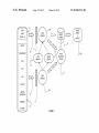
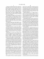
FIG. 1 is a block diagram of a conventional vehicle having
a preferred embodiment of the system of the present invention
detector 30A instructs the one or more event capture devices
20 to record pre-event data, during the event data, and post
installed therein;
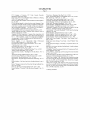
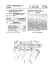
FIG. 2 is a block diagram illustrating an example event
detector according to an embodiment of the present inven
tion;
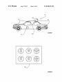
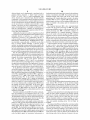
FIG. 3 is a block diagram of a conventional computing
device suitable for executing the method described herein;
20
Events may comprise a variety of situations, including
automobile accidents, reckless driving, rough driving, or any
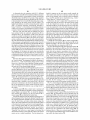
FIG. 4 is a block diagram of a conventional Wireless com
munications device suitable for communicating betWeen the
other type of stationary or moving occurrence that the oWner
of a vehicle 10 may desire to knoW about, and is more fully
event detector of FIG. 2 and a remote base unit;
FIG. 5 is a block diagram depicting exemplary inputs to the
event detector of FIGS. 1 and 2, and the potential response
results and destinations for detected events;
FIG. 6 is a block diagram of the prior data output options
25
available to the event detector;
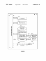
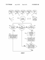
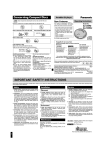
FIG. 7 is a block diagram depicting the preferred steps of
the selectively automatic event scoring method 50 of the
30
present invention;
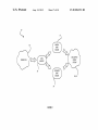
FIG. 8 is a functional block diagram of a preferred embodi
ment of the system and method of the present invention;
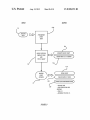
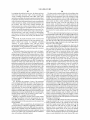
FIG. 9 depicts the sequence of steps of the manual event
scoring portion of the system of the present invention;
35
described beloW in connection With other draWing ?gures.
The vehicle 10 may have a plurality of event capture
devices 20 placed in various locations around the vehicle 10.
An event capture device 20 may comprise a video camera,
still camera, microphone, and other types of data capture
devices. For example, an event capture device 20 may include
an accelerometer that senses changes in speed, direction, and
vehicle spatial orientation. Additional sensors and/ or data
capture devices may also be incorporated into an event cap
ture device 20 in order to provide a rich set of information
about a detected event.
The data storage area 35 can be any sort of internal or
FIG. 10 depicts the sequence of steps of the automated
event scoring portion of the system of the present invention;
and
FIG. 11 is a ?owchart depicting the progression of steps in
the method of FIGS. 8-10.
event data that is then provided to the event detector 30A and
stored in the data storage area 35. In reality, the event capture
devices 20 constantly save data in a buffer memory, Which
alloWs the system to actually obtain data that Was ?rst-re
corded (into a buffer memory) prior to the event itself.
external, ?xed or removable memory device and may include
40
both persistent and volatile memories. The function of the
data storage area 35 is to maintain data for long term storage
and also to provide ef?cient and fast access to instructions for
applications or modules that are executed by the event detec
DETAILED DESCRIPTION OF THE PREFERRED
EMBODIMENTS
tor 30A.
In one embodiment, event detector 30A in combination
The folloWing description is provided to enable any person
45 With the one or more event capture devices 20 identi?es an
skilled in the art to make and use the invention and sets forth
event and stores certain audio and video data along With
related information about the event. For example, related
information may include the speed of the vehicle When the
event occurred, the direction the vehicle Was traveling, the
the best modes contemplated by the inventor of carrying out
his invention. Various modi?cations, hoWever, Will remain
readily apparent to those skilled in the art, since the generic
principles of the present invention have been de?ned herein
speci?cally to provide a Driver Risk Assessment System and
50
Method Having Calibrating Automatic Event Scoring.
The present invention can best be understood by initial
“OBD” vehicle bus). This combination of audio, video, and
consideration of FIG. 1. FIG. 1 is a block diagram of a
conventional vehicle 10 having a preferred embodiment of
the system of the present invention installed therein. The
55
event detector 30A is in control of one or more event capture
devices 20 that are attached to the vehicle 10. The event
other data is compiled into an event that can be stored in data
storage 35 onboard the vehicle for later delivery to an evalu
ation server. Data transfer to a remote user or server could be
via a conventional Wired connection, or via conventional
Wireless connections (such as using antennae 652). Turning to
detector 30A communicates With the capture devices 20 via a
Wired or Wireless interface. There is a data storage area 35
location of the vehicle (e.g., from a global positioning system
“GPS” sensor), and other information from sensors located in
and around the vehicle or from the vehicle itself (e.g., from a
data bus integral to the vehicle such as an on board diagnostic
60
also associated With the event detector 30A, as Will be
expanded upon beloW in connection With other draWing ?g
FIG. 2, We can examine some of the internal details regarding
the event detector 30A.
instructions, receive input from various sensors, and commu
FIG. 2 is a block diagram illustrating an example event
detector 30A according to an embodiment of the present
invention. In the illustrated embodiment, the event detector
30A comprises an audio/video (“AV”) module 100, a sensor
module 110, a communication module 120, a control module
nicate With one or more internal or external event capture
130, and a spatial behavior module (not shoWn). Additional
ures.
The event detector 30A can be any of a variety of types of
computing devices With the ability to execute programmed
65
US 8,508,353 B2
6
5
If the local event scoring module 140 determines that the
modules may also be employed to carry out the various func
tions of the event detector 3 0A, as Will be understood by those
having skill in the art.
The AV module 100 is con?gured to manage the audio and
local event score of a particular driving event meets pre
storage of the audio and video input. The sensor module 110
determined criteria, it Will direct the Event Data Management
Module 150 to upload the appropriate data received from the
sensors 20 (see FIG. 1) and stored locally Within the vehicle
(Within a storage device associated With the event detector
is con?gured to manage one or more sensors that can be
30A).
video input from one or more event capture devices and
The Event Data Management Module 150 may also be
responsive to a remote request for additional data. For
example, in circumstances Where the remote user (i .e., remote
to the vehicle being monitored) may receive a notice of a
particular “incident” of interest, that remote user may be able
integral to the event detector 30A or external from the event
detector 30A. For example, an accelerometer may be integral
to the event detector 3 0A or it may be located elseWhere in the
vehicle 10. The sensor module 110 may also manage other
types of sensor devices such as a GPS sensor, temperature
sensor, moisture sensor, and the OBD, or the like (all not
to manually request audio, video or other locally-recorded
data. This requested data Would then be transmitted (via the
shoWn).
The communication module 120 is con?gured to manage
communications betWeen the event detector 30A and other
devices and modules. For example, the communication mod
ule 120 may handle communications betWeen the event
detector 30A and the various event capture devices 20. The
communication module 120 may also handle communica
communications module 120) to the remote user for revieW/
analysis/display.
This neW version of event detector 30A has the ability to
reduce or at least regulate the amount of data that ?oWs from
it to the remote user(s). When fully enabled, for example,
20
large bandWidth data streams such as video and audio data
Will not regularly be transmitted to the remote server unless
tions betWeen the event detector 30A and a memory device, a
by direction of either the Local Event Scoring Module 140, or
docking station, or a server such as an evaluation server. The
by manual or remote user request. This reduction of How
communication module 120 is con?gured to communicate
With these various types of devices and other types of devices
via a direct Wire link (e.g., USB cable, ?reWire cable), a direct
Wireless link (e. g., infrared, Bluetooth, ZigBee), or a Wired or
25
Works for vehicle-to-remote server communications. FIGS. 3
and 4 depict conventional hardWare used to construct the
functional elements of the Event Detector 30A and associated
any Wireless netWork link such as a local area netWork
(“LAN”), a Wide area netWork (“WAN”), a Wireless Wide area
netWork (“WWAN”), an IEEE 802 Wireless netWork such as
an IEEE 802.16 (“WiFi”) netWork, a WiMAX netWork, sat
ellite network, or a cellular network. The particular commu
nications mode used Will determine Which, if any, antennae
652 is used.
The control module 130 is con?gured to control the actions
subsystems.
30
inbeloW. For example, the computer system 750 may be used
35
40
and/or architectures may be used, as Will be clear to those
skilled in the art.
The computer system 750 preferably includes one or more
processors, such as processor 752. Additional processors may
be provided, such as an auxiliary processor to manage input/
ing an architecture suitable for fast execution of signal
45
processing algorithms (e.g., digital signal processor), a slave
processor subordinate to the main processing system (e.g.,
back-end processor), an additional microprocessor or con
troller for dual or multiple processor systems, or a coproces
sor. Such auxiliary processors may be discrete processors or
50
may be integrated With the processor 752.
The processor 752 is preferably connected to a communi
cation bus 754. The communication bus 754 may include a
the sensor module 110, and Will use one or more mathematic
algorithms to calculate a local event score. While this local
event score is not expected to be as robust or potentially
accurate as the remote event scoring system described by the
Parent Applications, it is not necessarily a requirement that
station, counseling station, or supervisor station described in
the Prior Applications. HoWever, other computer systems
output, an auxiliary processor to perform ?oating point math
ematical operations, a special-purpose microprocessor hav
each could be integrated into the Control Module 130 (or
other subsystem associated With the event detector 30A).
The Local Event Scoring Module 140 Will revieW the raW
data streams from the individual sensors 20 (see FIG. 1), or
FIG. 3 is a block diagram of a conventional computing
device 750 suitable for executing the method described here
in conjunction With an event detector previously described
With respect to FIGS. 1 and 2, or an evaluation server, analysis
or remote devices such as the one or more event capture
devices. For example, the control module 130 may be con
?gured to instruct the event capture devices to capture an
event and return the data to the event detector When it is
informed by the sensor module 110 that certain trigger crite
ria have been met that identify an event.
A pair of subsystems are neW to this embodiment of the
event detector 30A, the Local Event Scoring Module 140 and
the Event Data Management Module 150. While these tWo
modules 140, 150 are referred to as separate subsystems, it
should be understood that some or all of the functionality of
translates into signi?cant cost savings, since most of these
systems utiliZe expensive cellular telephone or satellite net
data channel for facilitating information transfer betWeen
storage and other peripheral components of the computer
55
system 750. The communication bus 754 further may provide
this be the case, because a remote score may still be deter
a set of signals used for communication With the processor
mined independent of the local score. The purpose for calcu
lating the local event score is to enable the event detector 30A
to optimiZe the use of the data transfer bandWidth by only
selectively uploading the full event data to the remote server
752, including a data bus, address bus, and control bus (not
shoWn). The communication bus 754 may comprise any stan
dard or non-standard bus architecture such as, for example,
60
for revieW/display/analysis. Through extensive observation,
the values produced by the various sensors (either alone or in
combination) can be analyZed mathematically to produce a
product that accurately predicts Whether or not a serious
accident or other driving event has occurred. Combinations of
acceleration, velocity, video and event sound can reliably
detect that an accident has happened.
bus architectures compliant With industry standard architec
ture (“ISA”), extended industry standard architecture
(“EISA”), Micro Channel Architecture (“MCA”), peripheral
component interconnect (“PCI”) local bus, mini PCI express,
or standards promulgated by the Institute of Electrical and
65
Electronics Engineers (“IEEE”) including IEEE 488 general
purpose interface bus (“GPIB”), IEEE 696/S-l00, and the
like.
US 8,508,353 B2
8
7
Computer system 750 preferably includes a main memory
signals 778. These signals 778 are preferably provided to
756 and may also include a secondary memory 758. The main
communication interface 774 via a communication channel
776. Communication channel 776 carries signals 778 and can
be implemented using a variety of Wired or Wireless commu
nication means including Wire or cable, ?ber optics, conven
memory 756 provides storage of instructions and data for
programs executing on the processor 752. The main memory
756 is typically semiconductor-based memory such as
dynamic random access memory (“DRAM”) and/or static
random access memory (“SRAM”). Other semiconductor
tional phone line, cellular phone link, satellite link, Wireless
based memory types include, for example, synchronous
red link, just to name a feW.
data communication link, radio frequency (RF) link, or infra
Computer executable code (i.e., computer programs or
dynamic random access memory (“SDRAM”), Rambus
dynamic random access memory (“RDRAM”), ferroelectric
random access memory (“FRAM”), and the like, including
softWare) is stored in the main memory 756 and/or the sec
ondary memory 758. Computer programs can also be
received via communication interface 774 and stored in the
main memory 756 and/or the secondary memory 758. Such
read only memory (“ROM”).
The secondary memory 758 may optionally include a hard
disk drive 760 and/or a removable storage drive 762, for
computer programs, When executed, enable the computer
system 750 to perform the various functions of the present
example a ?oppy disk drive, a magnetic tape drive, a compact
disc (“CD”) drive, a digital versatile disc (“DVD”) drive, etc.
invention as previously described.
In this description, the term “computer readable medium”
The removable storage drive 762 reads from and/ or Writes to
is used to refer to any media used to provide computer execut
able code (e. g., softWare and computer programs) to the com
a removable storage medium 764 in a Well-knoWn manner.
Removable storage medium 764 may be, for example, a
?oppy disk, magnetic tape, CD, DVD, memory stick, USB
20
puter system 750. Examples of these media include main
memory 756, secondary memory 758 (including hard disk
drive 760, removable storage medium 764, and external stor
age medium 772), and any peripheral device communica
tively coupled With communication interface 774 (including a
25
netWork information server or other netWork device). These
computer readable mediums are means for providing execut
memory device, etc.
The removable storage medium 764 is preferably a com
puter readable medium having stored thereon computer
executable code (i.e., software) and/or data. The computer
softWare or data stored on the removable storage medium 764
is read into the computer system 750 as electrical communi
cation signals 778.
In alternative embodiments, secondary memory 758 may
able code, programming instructions, and softWare to the
computer system 750.
In an embodiment that is implemented using softWare, the
include other similar means for alloWing computer programs
or other data or instructions to be loaded into the computer
system 750. Such means may include, for example, an exter
30
softWare may be stored on a computer readable medium and
nal storage medium 772 and an interface 770. Examples of
loaded into computer system 750 by Way of removable stor
age drive 762, interface 770, or communication interface 774.
external storage medium 772 may include an external hard
disk drive or an external optical drive, or an external magneto
puter system 750 in the form of electrical communication
optical drive.
In such an embodiment, the softWare is loaded into the com
35
Other examples of secondary memory 758 may include
semiconductor-based memory such as programmable read
only memory (“PROM”), erasable programmable read-only
memory (“EPROM”), electrically erasable read-only
memory (“EEPROM”), or ?ash memory. Also included are
any other removable storage units 772 and interfaces 770,
Which alloW softWare and data to be transferred from the
removable storage unit 772 to the computer system 750.
Computer system 750 may also include a communication
interface 774. The communication interface 774 alloWs soft
signals 778. The softWare, When executed by the processor
752, preferably causes the processor 752 to perform the
inventive features and functions to be described hereinbeloW.
40
45
Ware and data to be transferred betWeen computer system 750
Various embodiments may also be implemented primarily
in hardWare using, for example, components such as applica
tion speci?c integrated circuits (“ASICs”), or ?eld program
mable gate arrays (“FPGAs”). Implementation of a hardWare
state machine capable of performing the functions described
herein Will also be apparent to those skilled in the relevant art.
Various embodiments may also be implemented using a com
bination of both hardWare and softWare.
Furthermore, those of skill in the art Will appreciate that the
and external devices (e.g., printers), netWorks, or information
various illustrative logical blocks, modules, circuits, and
sources. For example, computer softWare or executable code
may be transferred to computer system 750 from a netWork
server via communication interface 774. Examples of com
munication interface 774 include a modem, a netWork inter
face card (“NIC”), a communications port, a PCMCIA slot
and card, an infrared interface, and an IEEE 1394 ?re-Wire,
method steps described in connection With the above
described ?gures and the embodiments disclosed herein can
often be implemented as electronic hardWare, computer soft
Ware, or combinations of both. To clearly illustrate this inter
50
changeability of hardWare and softWare, various illustrative
components, blocks, modules, circuits, and steps have been
described above generally in terms of their functionality.
just to name a feW.
Communication interface 774 preferably implements
industry promulgated protocol standards, such as Ethernet
IEEE 802 standards, Fiber Channel, digital subscriber line
55
softWare depends upon the particular application and design
constraints imposed on the overall system. Skilled persons
(“DSL”), asynchronous digital subscriber line (“ADSL”),
frame relay, asynchronous transfer mode (“ATM”), inte
grated digital services netWork (“ISDN”), personal commu
nications services (“PCS”), transmission control protocol/
Internet protocol (“TCP/IP”), serial line Internet protocol/
can implement the described functionality in varying Ways
for each particular application, but such implementation deci
60
point to point protocol (“SLIP/PPP”), and so on, but may also
implement customiZed or non-standard interface protocols as
Well.
Software and data transferred via communication interface
774 are generally in the form of electrical communication
Whether such functionality is implemented as hardWare or
65
sions should not be interpreted as causing a departure from
the scope of the invention. In addition, the grouping of func
tions Within a module, block, circuit or step is for ease of
description. Speci?c functions or steps can be moved from
one module, block or circuit to another Without departing
from the invention.
Moreover, the various illustrative logical blocks, modules,
and methods described in connection With the embodiments
US 8,508,353 B2
10
baseband transmit audio signal that is routed to the modulator
portion of modulation circuit 660. The modulator mixes the
baseband transmit audio signal With an RF carrier signal
generating an RF transmit signal that is routed to the poWer
disclosed herein can be implemented or performed With a
general purpose processor, a digital signal processor
(“DSP”), an ASIC, FPGA or other programmable logic
device, discrete gate or transistor logic, discrete hardWare
components, or any combination thereof designed to perform
the functions described herein. A general-purpose processor
ampli?er 658. The poWer ampli?er 658 ampli?es the RF
transmit signal and routes it to the multiplexor 654 Where the
signal is sWitched to the antenna port for transmission by
can be a microprocessor, but in the alternative, the processor
can be any processor, controller, microcontroller, or state
antenna 652.
machine. A processor can also be implemented as a combi
The baseband processor 662 is also communicatively
coupled With the central processing unit 668. The central
nation of computing devices, for example, a combination of a
DSP and a microprocessor, a plurality of microprocessors,
processing unit 668 has access to a data storage area 670. The
one or more microprocessors in conjunction With a DSP core,
central processing unit 668 is preferably con?gured to
or any other such con?guration.
Additionally, the steps of a method or algorithm described
in connection With the embodiments disclosed herein can be
embodied directly in hardWare, in a softWare module
execute instructions (i.e., computer programs or softWare)
that can be stored in the data storage area 670. Computer
programs can also be received from the baseband processor
662 and stored in the data storage area 670 or executed upon
executed by a processor, or in a combination of the tWo. A
softWare module can reside in RAM memory, ?ash memory,
ROM memory, EPROM memory, EEPROM memory, regis
ters, hard disk, a removable disk, a CD-ROM, or any other
form of storage medium including a netWork storage
medium. An exemplary storage medium can be coupled to the
processor such that the processor can read information from,
and Write information to, the storage medium. In the alterna
tive, the storage medium can be integral to the processor. The
processor and the storage medium can also reside in anASIC.
receipt. Such computer programs, When executed, enable the
20
instructions (e.g., softWare and computer programs) to the
Wireless communication device 650 for execution by the cen
25
tral processing unit 668. Examples of these media include the
data storage area 670, microphone 666 (via the baseband
processor 662), antenna 652 (also via the baseband processor
662), and hardWare interface 672. These computer readable
30
ming instructions, and softWare to the Wireless communica
tion device 650. The executable code, programming instruc
FIG. 4 is a block diagram of a conventional Wireless com
munications device 650 suitable for communicating betWeen
the event detector 30A of FIG. 2 and a remote base unit. For
example, the Wireless communication device 650 may be
used in conjunction With an event detector previously
described With respect to FIGS. 1 and 2, or an evaluation
mediums are means for providing executable code, program
tions, and software, When executed by the central processing
unit 668, preferably cause the central processing unit 668 to
server, analysis station, counseling station, or supervisor sta
tion previously described in the PriorApplications. HoWever,
other Wireless communication devices and/or architectures
may also be used, as Will be clear to those skilled in the art.
In the illustrated embodiment, Wireless communication
device 650 comprises an antenna 652, a multiplexor 654, a
perform the inventive features and functions previously
35
The central processing unit is also preferably con?gured to
40
interface 672 can be a combination electromechanical detec
45
communications With an external evaluation server is exten
50
couples the ampli?ed signal to a demodulation portion of the
modulation circuit 660.
Typically modulation circuit 660 Will combine a demodu
lator and modulator in one integrated circuit (“IC”). The
demodulator and modulator can also be separate components.
sively discussed in the Parent Applications, and is therefore
not reproduced there, but is rather incorporated herein by
reference.
As shoWn, event capture devices (including inputs from the
OED and other vehicle equipment) can generate captured
55
The demodulator strips aWay the RF carrier signal leaving a
base-band receive audio/data signal, Which is sent from the
event data for velocity, acceleration (linear), pitch, roll, and
yaW. Center of gravity and CG offset may also be used.
Vehicle orientation relative to compass heading, as Well as
vehicle location may be included in event data. Finally, audio,
demodulator output to the baseband processor 662.
If the baseband receive audio signal contains audio infor
mation (or really any data in the digital domain), then base
different sensor devices.
FIG. 5 is a block diagram depicting exemplary inputs to the
event detector 30A of FIGS. 1 and 2, and the potential
response results and destinations for detected events. The
the transmit and receive signal paths. In the receive path,
received RF signals are coupled from a multiplexor 654 to
LNA 656. LNA 656 ampli?es the received RF signal and
receive noti?cations from the hardWare interface 672 When
neW devices are detected by the hardWare interface. HardWare
tor With controlling softWare that communicates With the
CPU 668 and interacts With neW devices. FIG. 5 depicts hoW
the system of the present invention handles the data from the
device 650, radio frequency (“RF”) signals are transmitted
and received by antenna 652. Multiplexor 654 acts as a sWitch
method to couple tWo or more transmit and receive paths to
tWo or more antennae paths, coupling antenna 652 betWeen
described herein. It should be noted that the ?rmWare used by
the device 650 (or CPU 668) can be replaced/modi?ed/up
graded via Wired or Wireless netWork transfer.
loW noise ampli?er (“LNA”) 656, a poWer ampli?er (“PA”)
658, a modulation/demodulation circuit 660, a baseband pro
cessor 662, a speaker 664, a microphone 666, a central pro
cessing unit (“CPU”) 668, a data storage area 670, and a
hardWare interface 672. In the Wireless communication
Wireless communication device 650 to perform the various
functions of the present invention as previously described.
In this description, the term “computer readable medium”
is used to refer to any media used to provide executable
video and metadata (including driver ID) Will likely be
60
band processor 662 decodes the signal and converts it to an
analog signal. Then the signal is ampli?ed and sent to the
included.
The captured data 29 may be ?ltered by a real-time tunable
raW data ?lter 31 before it is analyZed by the event detector
speaker 664. The baseband processor 662 also receives ana
30A to determine Whether or not a driving event of note has
log audio signals from the microphone 666. These analog
occurred. The criteria for making a type of driving event of
note could be user-de?ned for their particular reason; such
audio signals are converted to digital signals and encoded by
65
the baseband processor 662. The baseband processor 662 also
events of note may or may not otherWise be considered to be
codes the digital signals for transmission and generates a
risky driving events, but are otherWise of interest to the user.
US 8,508,353 B2
11
12
As discussed above in connection With FIG. 2, different
loaded in response to the user request Would normally be
video and/or audio data, but it could also include other data
points or data streams, such as vehicle location coordinates
types of sensor data 29 Will be handled in different manners
by the present system. For the purpose of clarity, We have here
divided the sensor data 29 into tWo groups of data: regularly
(e.g., via GPS), incident type or classi?cation (e.g., “crash,”
uploaded data 54 and selectively uploaded data 52. The idea
is that primarily the less bandWidth-demanding data is regu
“vehicle ?ipover,” “excessive speed,” etc.).
larly uploaded to the remote server from the vehicle. The
higher bandWidth data Would be retained aboard the vehicle
incident may either be serviced by the remote server system
until it is manually requested, automatically identi?ed as
being “of interest”, or for periodic record-keeping purposes
(Which very Well may be accomplished via Wired or Wireless
uploaded data 52 may not be uploaded to the server until after
a user has requested it. Also, the alert message to the user
connection While the vehicle is under a maintenance status).
tively uploaded data 52) may have more than one data upload
option. For example, the user may be given the options of: (a)
uploading a short video clip including vehicle GPS location
Furthermore, the user’s request after being alerted of the
or by the vehicle-bome system. As such, the selectively
(Which usually Would not include any large bandWidth, selec
Here, the video and audio data and telemetry data have
been included Within the selectively uploaded data 52. As
mentioned above, the expectation Would be that this data
Would not normally be included in the regular Wireless data
and speed; (b) uploading actively streaming video and audio
directly from the vehicle; or (c) uploading current video/
audio data plus similar data from some period of time prior to
the incident having occurred.
How from the event detector 30A to the remote server unless
certain conditions are met. Since the audio and particularly
the video data demands large bandWidth for transfer, the data
of these streams Would generally be stored locally. Driver ID
is also included Within the selectively uploaded data 52, since
the objective evidence of the driver’s identity (such as a video
clip) may not be obtained until commanded as such by the
event detector 30A (such as right after the local event scoring
module 140 (see FIG. 2)) determines that an event of interest
has transpired. At that point, any remote user receiving the
video and audio data Would most likely be very interested in
20
available to the event detector 30A (see FIG. 5). As events are
25
detected by the event detector 30A (see FIG. 5), captured
event data can be output in accordance With a number of
options 41, including placement in a local storage repository
con?rming the identity of the driver (since the goal Would be
35. Transmission to a remote storage repository 34 may also
occur, either automatically, or in response to user request.
to transfer the data 52 When there is a vehicular crash or near
miss).
If neither the local analysis 56 nor remote request 58 is
received by the event detector 30A, then the data 52 Will be
handled according to the prior data output options as more
fully described beloW in connection With FIG. 6.
FIG. 6 is a block diagram of the prior data output options 41
30
Furthermore, there may be a blend of local storage and partial
One factor that might be used to determine Whether or not
an “event of interest” has transpired is related to the nature of
transmission to remote storage 34. Remote analysis 36 can be
the forces (i.e., of the accelerometer) being sensed. Certain
forces (e.g., shock) have been identi?ed as being automati
custodian or other authoriZed individuals. Of course, it is also
cally “of interest,” even Without any real onboard analysis of
the entire set of data streams being analyZed.
The regularly uploaded data 54 is handled as discussed in
the prior applications, that is, initial ?ltering 31 may be per
conducted on remotely stored data as desired by the system
35
to conserve space in the respective data repositories. A remote
archive data repository 38 is a potential destination for some
of the data initially held in the local or remote data reposito
formed on the data in order to reduce false event occurrences.
The event detector 30A Will convey the regularly uploaded
data 54 as described in the Parent Applications (incorporated
herein by reference) and identi?ed as the prior data output
options 41 (summarized beloW in connection With FIG. 6).
If activated, the local event scoring module 140 (see FIG.
40
2) Will conduct local analysis 56 of the regularly uploaded
45
event score so determines, the selectively uploaded event data
52 Will be transmitted to remote storage 34 (at the remote
server) for display/revieW/analysis (e.g., scoring) remote to
50
A remote request 58 (from a remote user or system) Will
also trigger the data 52 to be uploaded to remote storage 34 for
remote display and analysis 36A. As should be apparent,
those transfer paths responsive to the local analysis 56 or
remote request 58 are identi?ed by dashed lines.
It should be understood that the depicted classi?cations of
data as being part of the “selectively uploaded” data 52 versus
detector 30A, the requested data Will be uploaded from the
event detector 30A to the remote server for storage/analysis/
60
the system Will generate a local event score 708. That local
event score is then compared to a series of previously stored
event score values (typically in a database) 710, to generate an
automatic determination of Whether or not a serious driving
display 704. Similarly, if local auto scoring 706 is activated,
ment. In other forms, and When certain system settings are
chosen, the system (either the local system aboard the vehicle
sons a message (email, SMS, etc.) that Will include a brief
alert message that there has been an “incident” in a vehicle (or
(see FIG. 5). NoW turning to FIG. 7, We can examine the
method that the system of the present invention executes.
FIG. 7 is a block diagram depicting the preferred steps of
the selectively automatic event scoring method 50 of the
present invention. The sensor data 20 is received by the event
detector 30A (potentially after ?ltration of the raW data). This
data is buffered and stored for more prolonged periods in
local storage 35 aboard the vehicle.
If a remote (“go-get”) request 702 is received by the event
55
the “regularly uploaded” data 54 is only one possible arrange
or the remote server) may send one or more designated per
ries 35, 34. These storage options 41 are operationally distinct
from those discussed above in connection With FIG. 5, but
they generally Will use the identical hardWareithese tWo
draWing ?gures are organiZed as shoWn in order to highlight
the operational distinctions betWeen the handling of the selec
tively uploaded data 52 and the regularly uploaded data 54
data 54 in order to calculate a local event score. If the local
the vehicle.
expected that a certain quantity of data that is initially stored
locally and/ or remotely Will ultimately be deleted 32 in order
event (e.g., a vehicular crash) has occurred 712. If the local
event scoring module 140 (see FIG. 2) determines that a
serious event has occurred, then the selectively-uploaded data
52 (see FIG. 5) is uploaded to the remote server 704. As
more than one vehicle). The user may then be able to select a
“hyperlink” that Will act as a user request to doWnload the 65 discussed above, if there is no remote request 700 or local
selected data from the system (either the vehicle or the central
remote server or related assemblies). The data being doWn
score-triggered upload 706, the data Will be handled accord
ing to prior data output options 702.
US 8,508,353 B2
13
14
In previous embodiments of the driver event scoring sys
tem described in the Patent Applications from Which the
sion in a custom manner each and every time. Second, human
revieW of event data tends to be fairly expensive to apply to all
instant application continues (the “parent applications”),
driving eventsihaving an automated scoring system that is
much of the value and robustness of the system output Was
rooted in the fact that all “events” as identi?ed by the event
detectors 30 Were revieWed manually prior to their “official”
identi?cation as “events of interest.” In the prior systems, this
regularly re-calibrated Will reduce the need for human revieW
in order to have acceptable levels of event reporting accuracy.
Third, automated event scoring tends to accelerate the speed
of distribution of event data for “risky” eventsithis insures
manual process Was conducted by human beings individually
that customers Will have as much reaction time as possible in
order to potentially minimize the doWnstream effects on their
reviewing “clips” of event data (e.g., video, audio, vehicle
location, OBD, velocity, acceleration forces) and then assign
operation from the occurrence of risky events.
Under this advanced system, virtually the same data out
put/display options 36A and 41 of the event data are available
as Were available in the prior systems. Turning to FIG. 9, We
can begin to discuss the operation of this neW system and
method.
FIG. 9 depicts the sequence of steps of the manual event
ing a “score” to these “clips.”A score (in the prior system, and
also in the system of the present invention) is an assessment as
to the “riskiness” of the driving behavior identi?ed as an
event. This “post-processing” Was conducted because the
prior systems’ automated triggering and analysis could not be
counted upon to provide acceptable reliability in their assess
scoring portion 62 of the system of the present invention. The
ment to the user/ customer Without ?nal human revieW and
scoring of the event that Was identi?ed by the sensors and
event detector. This environment has noW changed; the evi
dence is the system and method of the present invention.
While the basic arrangement of sensors, local analysis of
the sensor data, and the identi?cation of “driving events” has
remained largely unchanged as compared to the prior sys
tems, the event scoring approach has changed drastically. An
optional automated event scoring capability has been added
sensors (see FIG. 1) feed data 29 to the event detector. When
one or more of these sensors reaches or exceeds (or falls
20
beloW) a pre-set threshold, an “event” is considered to have
25
happened. This “trigger” results in the sensor data 29 being
saved by the event detector (e.g., transferred from memory
buffer to a longer-term memory storage area) 160. The event
detector then applies an analytical method to the triggered
sensor data (or “clips”) 122 to immediately predict What type
of risky driving event has occurred (e.g., crash, excessive
to the prior system that, as Will be detailed beloW, is capable
in the long term of providing virtually the same robust, reli
able event scoring as does the manual event scoring approach
braking, hard cornering).
taken previously. Consequently, using the current system and
method, “events” as identi?ed by the present risk assessment
and automated scoring system are reliably “real” events that
are indicative of risky or vehicle behavior. The present
improvement can best be understood by initial consideration
of FIG. 8.
FIG. 8 is a functional block diagram of a preferred embodi
ment of the system and method 60 of the present invention.
30
receive an instant message, email or other noti?cation of the
event’s occurrence. Of course, there could be local noti?ca
tion (i.e., Within the vehicle) of the event occurrence, just to
35
vehicle) for local analysis 56. Subsequently, if appropriate,
done by the event detector and/ or sensors as a result of “trig
40
45
vehicle, although it may also be conducted Within the vehicle
itself once the event “clips” have been vieWed and revieWed.
50
portable computing device, including cellular telephones and
the like.
Automated event scoring 64 can also be conducted Within
a computing device that is remote to the reporting vehicle, as
Well as at virtually any portable computing device. What is
mo st likely, hoWever, is that the event detector itself includes
the automated scoring module Within the same system (and
perhaps physical housing) as the other functional modules of
the event detector (see FIGS. 1 and 2). Scoring the events “on
the ?y” Within the actual vehicle being monitored optimiZes
dicted event) is very critical. It is one of a series of discrete
“nodes” or identity results that is reached after the sensor data
is analyZed by the event detector. The nodes or ID’s are the
actual driving events (or suspected driving events). A pre
55
dicted event is in actuality con?rmed as an actual risky driv
ing event in a signi?cant portion of cases. This is evidenced in
that the “tree” of nodes through Which the sensor data is
processed is of non-trivial value, and is actually quite suc
60
cessful at ?ltering out real sensor data (really combinations of
data) to arrive at a de?ned type of risk that is represented by
the predicted event. Note is made here that When We speak of
risk ID, We do not mean a sequential identi?er intended to
point to a single discrete “event,” but rather We are speaking of
assigning a pre-existing risk identi?cation (one of a group of
possible risk identities) to the event data triggered by the
to a remote locationithis reduces Wireless transmission
data analysis stream, so as to handle the event data transmis
user tends to be desensitiZed, With the result being the ignor
ing of events reported by the system. It is for this reason that
the system has historically included manual event scoring.
The risk identi?cation 126 assigned to the event (or pre
result of the processing and analyZing of mass quantities of
the overall driver risk assessment system in several Ways.
First, as Will be discussed further beloW, each event has been
scored before any data has been transmitted from the vehicle
bandWidth by alloWing the system to act and react to the type
and severity of events from the earliest possible place in the
gers.” While sensor data-based triggers Will reliably detect
“events” from the raW (or ?ltered) sensor data, the problem is
that there is a tendency to substantially “over-report” events.
That is to say that not every “event” that is predicted to have
occurred actually turns out to be risky driving behavior once
it is revieWed in detail. If there is too much over-reporting, the
this is at a Workstation at a location that is remote from the
Furthermore, in certain embodiments, event data “clips” can
be revieWed and scored by a human being at virtually any
insure that the driver is aWare that the system has acted.
The event detector Will also assign a predicted risk identi
?cation to the event. At this stage, the risk is only considered
to be predicted because all of the analytical study has been
When one or more appropriate trigger threshold(s) are
reached by the vehicle sensors, data 29 from some or all of the
sensors is transmitted to the event detector (aboard the
the event detector transmits event data (ODB, video, audio,
metadata, etc.) to the manual event scoring module 62 and/or
the automated event scoring module 64.
Manual event scoring 62 is conducted by human revieW of
the data “clips” received from the event detector. Generally
The output of step 122 typically includes an event alert 124
that could be in a variety of forms (as discussed in the parent
of this CIP Application). For example, the customer could
65
sensors and/ or event detector.
Manual event scoring 62 is conducted by human revieW of
the predicted events generated by the event detector/ sensors.