1
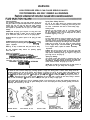
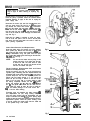
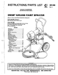
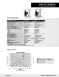
Parts
WARNING
HIGH PRESSURE SPRAY CAN CAUSE SERIOUS INJURY.
General Safety
This equipment generates very high fluid pressure. Spray from
the gun, leaks or ruptured components can inject fluid
through your skin and into your body and cause extremely
serious bodily injury, including the need for amputation. Also,
fluid injected or splashed into the eyes can cause serious
damage.
NEVER point the spray gun at anyone or at any part of the
body. NEVER put hand or fingers over the spray tip. NEVER
try to “blow back” paint; this is NOT an air spray system.
ALWAYS have the tip guard in place on the spray gun when
spraying.
ALWAYS follow the Pressure Relief Procedur?, . below,
before cleaning or removing the spray tip or servlcrng any
system equipment.
NEVER try to stop or deflect leaks with your hand or body.
Be sure equipment safety devices are operating properly
before each use.
Medical Treatment
If any fluid ap ears to enetrate our skrh
et
EMEhENCY hEDICAi CAR6 &T ONCE.
DO NOT TREAT AS A SIMPLE CUT.
Tell the doctor exactly what fluid was injected. For treatment
instructions, have your doctor call the
NATIONAL POISON CENTEP NETWORK
(412)681-6668 .
,-
r
Spray Gun Safety Devices
Be sure all gun safety devices are operating properly before
each use. Do not remove or modify any part of the gun; this
can cause a malfunction and result in serious bodily injury.
Safety Latch
Whenever you stop spraying, even for a moment, always set
the gun safety latch in the closed or “safe” position, making
the gun inoperative. Failure to set the safety latch can result in
accidental triggering of the gun.
Diffuser
The gun diffuser breaks up spray and reduces the risk of injection when the tio is not installed. Check diffuser operation
regularly. Follow’ the Pressure Relief Procedure,’ below,
then remove the spray tip. Aim the gun into a metal pail,
holding the gun firmly to the pail. Using the lowest possible
pressure, trigger the gun. If the fluid emitted Is not diffused into an irregular stream, replace the diffuser immediately.
Tip Guard
ALWAYS have the tip guard in place on the spray gun while
spraying. The tip guard alerts you to the injection hazard and
helps prevent accidentally placing your fingers or any part of
your body close to the spray tip.
Spray Tip Safety
Use extreme caution when cleaning or changing spray tips. If
the spray tip clogs while spraying, engage the gun safety latch
immediately. ALWAYS follow the Pressure Relief Procedure and then remove the spray tip to clean it.
NEVER wipe off build up around the spray tip until pressure is
fully relieved and the gun safety latch is engaged.
Pressure Relief Procedure
To reduce the risk of serious bodily injury, including injection or injury from moving parts or electric shock, always follow this
procedure whenever you shut off the sprayer, when checking or servicing any part of the spray system, when installing, cleaning or changing spray tips, and whenever you stop spraying. (1) Engage the gun safety latch. (2) Turn the ON/OFF switch to
OFF. (3) Unplug the power supply cord. (4) Disengage the gun safety latch. (5) Hold a metal part of the gun firmly to the side of
a metal pail, and trigger the gun to relieve pressure. (6) Engage the gun safety latch. (7) Open the drain valve, having a container
ready to catch the drainage. (8) Leave the drain valve open until you are ready to spray again.
If you suspect that the spray tip or hose is completely clogged, or that pressure has not been fully relieved after following the
steps above, VERY SLOWLY loosen the tip guard retaining nut or hose end coupling and relieve pressure gradually, then loosen
completely. Now clear the tip or hose.
ENGAGE SAFETY
2
307460
TURN SWITCH TO OFF
UNPLUG CORD
DISENGAGE SAFETY
AND TRIGGER GUN;
ENGAGE SAFETY AGAIN
OPEN DRAIN VALVE
FIRE OR EXPLOSION HAZARD.
General
Safety
Any misuse of the spray equipment or accessories, such as
overpressurizing, modifying parts, using incompatible
chemicals and materials, or using worn or damaged parts, can
cause them to rupture and result in injection or other serious
bodily injury, fire, explosion or property damage.
NEVER alter or modify any part of this equipment; doing s o
could cause it to malfunction.
CHECK all spray equipment regularly and repair o r replace
worn or damaged parts immediately.
System Pressure
.‘- (.l
Static electricity is created by the high velocity flow of fluid
through the pump and hose. If every part of the spray equipment is not properly grounded, sparking may occur, and the
system may become hazardous. Sparking may also occur
when plugging in or unplugging a power supply cord. Sparks
can ignite fumes from solvents and the fluid being sprayed,
dust particles and other flammable substances, whether you
are spraying indoors or outdoors, and can cause a fire or explosion and serious bodily injury and property damage.
Always plug the sprayer into an outlet at least 20 feet (6 m)
away from the sprayer and the spray area. Do not plug in or
unplug any power supply cords in the spray area when there is
any chance of igniting fumes still in the air.
This soraver can develoo 2750 osi 173J bar) MAXIMUM
WORkINk PRESSURE. Be sure that ail spray equipment and
accessories are rated to withstand the maximum working
pressure of this sprayer. DO NOT exceed the maximum working pressure of any component or accessory used in the
system.
Groundin
Material Corn atibility
1.
plug the power supply cord, or extension cord,
each equipped with an undamaged three-prong plug, into
a properly grounded outlet. Do not use an adapter. All extension cords must have three wires and be rated for 15
amps.
HOSE SAFETY
2.
Fluid hoses:
High pressure fluid in the hoses can be very dangerous. If the
hose develops a pinhole leak, split or rupture due to any kind
of wear, damage or misuse, the high pressure spray emitted
from it can cause an injection injury or other serious bodily injury or property damage.
3.
Spray gun:
4.
Object
5.
All solvent pails used when flushing,
code. Use only metalpails, which are
6.
To maintain grounding continuity when flushing or relieving pressure, always hold a metal part of the gun firmly to
the side of a metal pail, then trigger the gun.
To reduce tf e risk of static sparking, ground the sprayer and
all other spray equipment used or located in the spray area.
CHECK your local electrical code for detailed grounding instructions for your area and type of equipment. BE SURE to
ground all of this spray equipment:
BE SURE that alP materials and solvents used are chemically
compatible with the wetted parts shown in the Technical Data
on the back cover. Always read the material and solvent
manufacturer’s literature before using them in this sprayer.
ALL FLUID HOSES MUST HAVE SPRING GUARDS! The
spring guards help protect the hose from kinks or bends at or
close to the coupling which can result in hose rupture.
TIGHTEN all fluid connections securely before each use. High
pressure fluid can dislodge a loose coupling or allow high
pressure spray to be emitted from the coupling.
NEVER use a damaged hose. Before each use, check entire
hose for cuts, leaks, abrasion, bulging cover, or damage or
movement of the hose couplings. If any of these conditions
exist, replace the hose immediately. DO NOT try to recouple
high pressure hose or mend it with tape or any other device. A
repaired hose cannot contain the high pressure fluid.
HANDLE AND ROUTE HOSES CAREFULLY. Do not pull on
hoses to move equipment. Do not use materials or solvents
which are not compatible with the inner tube and cover of the
hose. DO NOT expose the hose to temperatures above WOOF
W°C) or below -4OOF (-4OOC).
Hose Grounding Continuity
The fluid hoses provided with this sprayer have electrically
conductive material on the surface of the center core of the
hose. Other hoses on the market may have a ground wire extending the length of the hose. The ground wire can break in
use which will destroy the electrical grounding of the hose.
Sprayer:
use only grounded hoses with a maximum of
500 feet (150 m) combined hose length to ensure grounding continuity. Refer to Hose Grounding Continuity.
obtain grounding through connection to a
properly grounded fluid hose and sprayer.
being
sprayed:
according to local code.
according to local
conductive. Do not
place the pail on a non-conductive surface, such as paper
or cardboard, which interrupts the grounding continuity.
Flushin
Safety
Reduce ti! e risk of injection injury, static sparking, or splashing
by following the specific flushing procedure given on page 9
of this manual. Follow the Pressure Relief Procedure on
page 2, and remove the spray tip before flushing. Hold a
metal part of the gun firmly to the side of a metal pail and use
the lowest possible fluid pressure during flushing.
.
MOVING PARTS HAZARD’
Moving parts can pinch or
body parts. KEEP CLEAR of
operating the sprayer. Unplug
before checking or servicing
starting accidentally.
amputate your fingers or other
moving parts when starting or
the sprayer and relieve pressure
the sprayer to prevent it from
To be sure of continuity, check electrical resistance at least
once a week. Check overall resistance when using multiple
hose assemblies. If the resistance exceeds 29 megohms,
replace it immediately. Ground wire hose may have different
resistance; check supplier.
IMPORTANT
United States Government safety standards have been adopted under the Occupational Safety and Health Act. These standards-particularly the General Standards, Part 1910, and the Construction Standards, Part 1926-should
be consulted.
307460
3
A VERTISSEMENT
La pulv&isation
A haute pression peut causer des blessures tr&s graves.
R6serv6 exclusivement & I’usage professionnel. Observer toutes les consignes de s&wit&
Bien lire et bien comprendre tous les manuels d’instructions avant d’utiliser le mat6riel.
Consignes g6n6rales
enlever ni modifier une partie quelconque du pistolet; ceci risquerait d’entrainer un mauvais fonctionnement et des
blessures graves.
Verrou de s&wit&
A chaque fois que I’on s’arrkte de pulveriser, mQme s’il s’agit
d’un court instant, toujours mettre le verrou de securite du
pistolet sur la position “fermee” ou “securite” (“safe”) pour
empkher le pistolet de fonctionner. Si le verrou de securite
n’est pas mis, le pistolet peut se dtklencher
accidentellement.
Diffuser
Le diffuseur du pistolet sert B diviser le jet et a reduire les risques d’injection accidentelle quand I’ajutage n’est pas en
place. Verifier le fonctionnement du diffuseur regulierement.
Pour cette verification, detendre la pression en observant la
Marche a Suivre pour Ddtendre la Pression donnee plus
loin puis enlever I’ajutage du pulverisateur. Pointer le pistolet
dans un seau en metal, en le maintenant fermement contre le
seau. Puis, en utilisant la pression la plus faible possible, appuyer sur la gachette du pistolet. Si le fluide projete n’estpas
diffuse sous forme de jet irregulier,
remplacer immediatement
le diffuseur.
Protection de l’aju tage
TOUJOURS maintenir la protection de I’ajutage en place sur f e
pistolet du pulverisateur pendant la pulverisation. La protection de I’ajutage attire I’attention sur les risques d’injection et
contribue B eviter que les doigts ou une partie quelconque du
corps ne passe accidentellement B proximite immediate de
I’ajutage du pulverisateur.
de skuritd
Cet appareil produit un fluide 8 tres haute pression. Le fluide
pulverise par le pistolet ou le fluide sous pression provenant de
fuites ou de ruptures peut penetrer sous la peau ou a I’interieur
du corps et entrainer des blessures tres graves, voir mQme une
amputation. MQme sans Qtre sous pression, le fluide bclaboussant ou entrant dans les yeux peut aussi entrainer des
blessures graves.
NE JAMAIS pointer le pistolet vers quelqu’un ou vers une partie quelconque du corps. NE JAMAIS mettre la main ou les
doigts sur I’ajutage du pulverisateur. NE JAMAIS essayer de
“refouler” la peinture. Cet appareil N’est PAS un compresseur
pneumatique.
TOUJOURS garder la protection de I’ajutage en place sur le
pistolet pendant la pulverisation.
TOUJOURS observer la March g Suivre pour D6tendre la
Pression don&e plus loin, avant de nettoyer ou d’enlever
I’ajutage du pulverisateur, ou d’effectuer un travail quelconque sur une partie de I’appareil.
NE JAMAIS essayer d’arrQter ou de devier les fuites avec la
main ou le corps.
Avant chaque utilisation, bien s’assurer que les dispositifs de
securite fonctionnent correctement.
Soins mddicaux
En cas de pen&ration de fluide sous la peau:
DEMANDER IMMEDIATEMENT
DES SOINS
MEDICAUX
D’URGENCE.
NE PAS SOIGNER CE7TE BLESSURE COMME
UNE SIMPLE COUPURE.
Dire exactement au medecin quel type de liquide a 6te inject&
Pour avoir des instructions concernant le traitement approprie, dire au medecin d’appeler le
CENTRE ANTI-POISON SUIVANT:
NATIONAL POISON CENTER NETWORK
Consianes
de skurit4 concernant I’ajutage du
pulvklsateur
Faire extramement
attention B l’occasion du nettoyage ou du
remplacement des ajutages du pulverisateur. Si l’ajutage se
bouche pendant la pulverisation, mettre immediatement le
verrou de securite du pistolet. TOUJOURS bien observer la
Marche g Suivre pour Ddtendre la Pression puis enlever
I’ajutage du pulverisateur pour le nettoyer.
NE JAMAIS essuyer ce qui s’est accumule autour de I’ajutage
du pulverisateur avant que la pression ne soit completement
tombee et que le verrou de securite du pistolet ne soit engage.
(412)681-6669
Avant chaque utilisation, bien s’assure que tous les dispositifs
de securite du pistolet fonctionnent correctement. Ne pas
Marche A Suivre pour D6tendre la Pression
Pour reduire les risques de blessures graves, y compris les blessures par injection de fluide ou celles causees par des pieces en
mouvement ou par electrocution, toujours bien observer cette marche a suivre B chaque fois que I’on arrQte le pulverisateur, B
I’occasion de la verification ou de la reparation d’une piece de I’appareil de pulverisation, 8 I’occasion de I’installation, du nettoyage ou du remplacement des ajutages et d’une man&e g&n&ale a chaque arr9t. 1) Engager le verrou de securite du pistolet.
2) Mettre I’interrupteur Marche-Arrat
sur ARRET (“OFF”). 3) Debrancher le cordon d’alimentation. 4) Desengager le verrou de
securite du pistolet. 5) En maintenant une partie metallique du pistolet fermement appuyee contre le c&e d’un seau en metal,
appuyer sur la gachette du pistolet pour liberer la pression. 6) Engager le verrou de securite du pistolet. 7) Ouvrir le robinet de
purge en prenant soin d’avoir un recipient prQt B recuperer le liquide. 8) Laisser le robinet de purge ouvert jusqu’a ce que le
pulverisateur soit de nouveau prQt a &re utilise.
Sil’on soupconne que l’ajutage du pulvkisateur ou le tuvau est complktement bouchh, ou que la pression n’a pas BttS complktement lib&&e apr&s avoir proc&d& aux opkrations ci-dessus, desserrer TRES LENTEMENT l’ecrou
de retenue de la protection de
I’ajutage ou le raccord du bout du tuyau et liberer progressivement la pression, puis terminer le desserrage. On peut maintenant
debaucher
I’ajutage ou le tuyau.
MA
1
2
3
‘L&6
7
RISQUES
EN CAS DE MAUVAISE UTILISATION
DU MATERIEL
Consignes g6n&ales de skurit4
Pression
Toute utilisation anormale de I’appareil de pulverisation ou des
accessoires comme, par exemple, la mise sous une pression
excessive, les modifications de pieces, I’utilisation de produits
chimiques et de matieres incompatibles et I’utilisation de
pieces us&es ou abimees peut causer des deg&s B I’appareil ou
des ruptures de pieces et entrainer une injection de liquide ou
d’autres blessures serieuses, un incendie, une explosion ou
d’autres degats.
Ce pulverisateur peut produire une PRESS/ON MAXIMUM DE
TRAVAIL l&W bar 12750 lb/po.2). S’assurer que tous les
elements du pulverisateur et ses accessoires sont concus pour
resister a la pression maximum de travail de ce pulverisateur.
NE PAS depasser la pression maximum de travail d’aucun des
elements ou accessoires utilises avec cet appareil.
NE JAMAIS alterer ou modifier une piece de cet appareil; ceci
risquerait d’entrainer son mauvais fonctionnement.
VERIFIER regulierement tout I’appareil de pulverisation et ses
equipements et &parer ou remplacer immediatement les
pieces u&es ou abimees.
MESURES DE SECURITE
TOUS LES TUYAUX FLEXIBLES DOIVENT AVOIR DES
RESSORTS SPIRALE DE PROTECTION! Les spirales de
protection contribuent 8 eviter la formation de pliures, de
boucles ou de noeuds sur les tuyaux qui pourraient entrainer la
rupture du tuyau 8 I’endroit du raccord ou a son voisinage.
SERRER FERMEMENT tous les raccords avant chaque utilisation. Le fluide sous pression peut faire sauter un raccord
desserre ou produire un jet a haute pression s’echappant par le
raccord.
NE JAMAIS utiliser un tuyau endommage. Avant chaque
utilisation, verifier entierement chaque tuyau pour deceler les
coupures, fuites, abrasions, boursouflures de I’enveloppe ou
toute autre deterioration ou jeu des raccords. Si I’on constate
I’une de ces deteriorations, il faut remplacer le tuyau immediatement. NE PAS essayer de refaire le raccord d’un tuyau
haute pression ni de reparer le tuyau avec du ruban adhesif ou
D’INCENDIE
OU
BIEN
S’ASSURER que tous les corps des solvants utilises
sont chimiquement compatibles avec les parties mouilkes indiquees dans les “Donnees techniques”, au dos de la couverture. Toujours lire soigneusement les documents et brochures
du fabricant des mat&es et solvants utilises avant de s’en servir dans ce pulverisateur.
CONCERNANT LES T U Y A U X
Le fluide a haute pression circulant dans les tuyaux peut &re
tres dangereux. En cas de fuite sur le tuyau, mQme minuscule,
de fissure, dechirure ou rupture a la suite de I’usure, de degfits
ou d’une mauvaise utilisation, les projections de fluide haute
pression qui en proviennent peuvent entrainer des blessures
graves par penetration sous la peau ou par contact, ainsi que
des deggts materiels.
RISQUES
Compatibilit4 chimique des corps
FLEXIBLES
par tout autre moyen. Un tuyau repare ne peut pas resister au
fluide sous pression.
MANIPULER L E S T U Y A U X A V E C P R E C A U T I O N E T
CHOISIR SOIGNEUSEMENT LEUR CHEMIN. Ne pas deplacer
le materiel en tirant sur le tuyau. Ne pas utiliser de mat&es ou
de solvants qui ne sont pas compatibles avec I’enveloppe interieure ou exterieure du tuyau. NE PAS exposer le tuyau a
des temperatures superieures a 82°C (18OOF)
ou inferieures a
-40°C (-4OOF).
Continuitd du circuit de mise A la terre des tuyaux
Les tuyaux flexibles fournis avec ce pulverisateur ont une surface conductrice continue au coeur du tuyau. D’autres tuyaux
vendus dans le commerce cornportent un fil de mise a la terre
allant tout au long du tuyau. Ce fil de mise a la terre peut se
rompre a I’usage, ce qui supprime la mise a la terre du tuyau.
Pour &re certain de la continuite de la mise a la terre, il faut
verifier la resistance Blectrique des tuyaux au moins une fois
par semaine. Verifier aussi la resistance d’ensemble quand il y
a plusieurs tuyaux assembltk
Si la resistance depasse 29
megohms, remplacer immediatement le tuyau. La resistance
des tuyaux mis a la terre par un fil peut Qtre differente; se
renseigner aupres du fournisseur.
\
D’EXPLOSION
De l’electricite statique est produite par le passage du fluide a
grande vitesse dans la pompe et dans les tuyaux. Si toutes les
pieces de I’appareil de pulverisation ne sont pas convenablement reliees a la masse ou B la terre, des etincelles peuvent se
produire et I’appareil risque d’9tre dangereux. Des Btincelles
peuvent egalement se produire a I’occasion du branchement
ou du debranchement du cordon d’alimentation. Les etincelles
sont suffisantes pour allumer les vapeurs de solvants et le
fluide pulverise, les fines particules de poussiere ainsi que
d’autres substances inflammables, quand on pulverise a I’interieur ou 8 I’exterieur, et elles peuvent causer un incendie ou
une expiosion, ainsi que des blessures graves et des deggts
materiels. Toujours brancher le pulverisateur dans une prise se
trouvant a au moins 6 m (20 pieds) de I’appareil et de I’endroit
oti se fait la pulverisation. Ne pas brancher ou debrancher un
cordon d’alimentation quel qu’il soit dans la zone ou se fait la
pulverisation quand il y a le moindre risque que des vapeurs
encore presentes dans I’air prennent feu.
Mise & la terre ou A la masse
Pour reduire les risques de production d’etincelles d’electricite
statique, le pulverisateur et tous les equipements utilises ou se
trouvant dans la zone de pulverisation doivent Qtre relies a la
terre ou a la masse. Pour connaitre le detail des instructions de
mise ZI la terre dans la region et le type particulier d’equipement, CONSULTER le code ou les reglementations electriques
locales. S’ASSURER que tous les equipements de pulverisation suivants sont bien relies a la terre:
1. Pulwkisateur: Brancher le cordon d’alimentation ou la
rallonge qui doivent Qtre equip& d’une prise 8 3 fiches en bon
&at, dans une prise de courant convenablement mise a la
terre. Ne pas utiliser d’adaptateur. Toutes les rallonges doivent
avoir 3 fils et &re prevues pour 15 amperes.
;.
2. Tuyaux flexibles:
Afin d’assurer la continuite de la mise a la
terre, n’utiliser que des tuyaux comportant une mise a la terre
e t a y a n t u n e l o n g u e u r m a x i m u m combinee d e 1 5 0 m
(1500
pieds). Se reporter egalement au paragraphe “Con-
tinuitb du circuit de mise A la terre des tuyaux”.
3. Pistolet: Realiser la mise 8 la terre en le raccordant a un
tuyau flexible et a un pulverisateur deja convenablement relies
a la terre.
4. Objets, mattkiel ou surfaces recevant la pulv&isation:
observer le code ou les reglementations locales.
5. Tous /es seaux de so&ants utilises pour le rincage: observer
le code ou les reglementations locales. N’utiliser que des seaux
m&a//iques conducteurs de l’electricite. Ne pas mettre le seau
sur une surface non conductrice comme sur du papier ou du
carton car cela interromprait la continuite le la mise a la terre.
6. Pour conserver la continuith de la mise B la terre quand on
rince le matkriel ou quand on lib&e la pression, toujours
maintenir une partie metallique du pistolet fermement appuyee
contre le cot& d’un seau en m&a/ puis appuyer sur la detente
du pistolet.
Mesures de Sdcurit4 concernant le Rincage
Pour reduire les
peau et les risques
aux eclaboussures,
donnee a la page
risques de blessures par penetration de la
dirs aux etincelles d’electricite statique ou
observer la marche a suivre pour le rincage
9 de ce manuel. Observer la “Marche &
Suivre pour Dbtendre la Pression” donnee a la page 4 en
enlever
l’ajutage du pulv&isateur avant le rincage.
Maintenir
une partie metallique du pistolet fermement appuyee contre le
tote d’un seau en m&al et utiliser la pression la plus faible
possible pendant le rincage.
307460
5
ADVERTENCIA
EL ROCIADO A ALTA PRESION PUEDE CAUSAR GRAVES LESIONES.
SOLO PARA US0 PROFESIONAL. RESPETE LOS AVISOS DE ADVERTENCIA.
Lea y entienda todo el manual de instrucciones antes de manejar el equipo.
PEUGRO DE Iff YECCION DE FLUID0
Seguridad general
Aparatos de seguridad de la pistola pulverizadora
Este equip0 genera un fluid0 a una presion muy alta. El
rociado de la pistola, 10s escapes de fluid0 o roturas de 10s
componentes pueden inyectar fluid0 en la piel y el cuerpo y
causar lesiones extremadamente graves, incluyendo a veces la
necesidad de amputacibn. Tambien, el fluid0 i n y e c t a d o o
salpicado en 10s ojos puede causar graves dafios.
Asegurar que todos 10s aparatos protectores de la pistola
estan f u n c i o n a n d o b i e n a n t e s d e cada u s o . N o sacar n i
modificar ninguna pieza de la pistola pues podria causar el
malfuncionamiento de la misma con las consiguientes lesiones
personales.
NUNCA apuntar la pistola hacia alguien o alguna parte del
cuerpo. NUNCA colocar la mano o 10s dedos encima de la boquilla.
NUNCA tratar de “hater retornar la pintura”; este NO
es un sistema de rociado de aire.
Cada vez que se deje de pulverizar, aunque sea por un breve
momento, siempre colocar el pestillo de seguridad en la
position “cerrada”, lo que deja la pistola inoperante. El no
hacerlo puede llevar al disparo imprevisto de la pistola.
SIEMPRE tener colocado el protector de la boquilla en la
pistola mientras se esta pulverizando.
Difusor
Pestillo de segut-idad
Asegurar que todos 10s aparatos de seguridad del equip0
estan funcionando bien antes de cada uso.
El difusor de la pistola dispersa el chorro pulverizado y reduce
el riesgo de inyeccion cuando no esta instalada la boquilla.
Revisar con regularidad el funcionamiento del difusor. Seguir
el procedimiento de descarga de presibn, dado mas abajo,
y despues sacar la boquilla. Apuntar la pistola a un balde
metalico, sosteniendola bien firme contra 61. Utilizando la
presion m&r bajo posible, disparar la pistola. Si el fluid0
emitido no sale disperse
en un chorro irregular, reemplazar de
inmediato el difusor.
Tratamiento medico
Protector de la boquilla
SIEMPRE seguir el procedimiento de descarga de presibn,
dado m& abjo, antes de limpiar o sacar la boquilla o de dar
servicio a cualiquier equip0 del sistema.
NUNCA tratar de parar o desviar 10s escapes con la mano o el
cuerpo.
SIEMPRE tener el protector de ia boquilla colocado en la
pistola mientras se esta pulverizando. Este protector llama la
atencion contra el peligro de inyeccibn y ayuda a prevenir la
colocacion accidental de 10s dedos o cualquier otra parte del
cuerpo cerca de la boquilla.
Si pareciera que un poco de fluid0 penetro la piel, conseguir
TRATAMIENTO MEDICO DE URGENCIA
DE
INMEDIATO.
NO TRATAR LA HERIDA C O M O U N S I M P L E C O R T E .
Decir al medico exactamente cua fluid0 fue. Para instrucciones de tratamiento, pedir al medico que llame a la
CADENA DEL CENTRO NACIONAL DE
ENVENENAMIENTO
Seguridad de la boquilla pulverizadora
Tener mucho cuidado al limpiar o cambiar las boquillas. Si
llegara a obstruirse mientras esta pulverizando, enganchar el
pestillo de la pistola de inmediato. SIEMPRE seguir el procedimiento de descarga de presih y despues sacar la boquilla para limpiarla.
NUNCA limpiar la acumulacion de pintura alrededor de la boquilla
antes de que se haya descargado por complete la
presion y el pestillo este enganchado.
Procedimiento de descarga de presih
Para reducir el riesgo de sufrir graves lesiones corporales, rncluyendo inyeccion o lesiones causadas por piezas en movimiento o
choque electrico, siempre seguir este procedimiento al apagar la maquina pulverizadora, al revisar o dar servicio a cualquier parte
del sistema de pulverizacibn, al instalar, limpiar o cambiar las boquillas, y cada vez que se deja de pulverizar. (1) Enganchar el
pestillo de la pistola. (2) Mover el interruptor electrico (ON/OFF) a la position OFF (apagado). (3) Desenchufar el cordon
ektrico. (4) Desenganchar el pestillo de la pistola. (5) Sujetar una parte mettilica de la pistola bien firme contra un balde de
metal, y disparar la pistola para descargar la presibn. (6) Enganchar el pestillo de la pistola. (7) Abrir la valvula de drenaje y tener
listo un reclipiente para recibir la pintura. (8) Dejar la valvula de drenaje abierta hasta que se este nuevamente listo para
pulverizar.
Sise sospecha que la boquilla o la manguera est4 completamente obstruida, o que no se ha descargado por complete la presidn
despuh de haber seguido elprocedimiento anterior, aflojar MUY LENTAMENTE la tuerca de retention del protector de la boquilla o acoplamiento de la punta de la manguera y descargar gradualmente la presibn, despues, aflojarlo por complete. Luego,
despejar la boquilla o la manguera.
1
6
307460
2
3
456
7
PELIGRO POR MAL US0 DEL EQUIP0
PELIGRO DE INCENDIO 0 EXPLOSIOhl
Seguridad eneral
El flujo a alta velocidad del fluid0 al pasar por la bomba y
manguera crea electricidad estatica. Si todas las partes del
equip0 pulverizador no tienen buena tierra, pueden ocurrir
chispas, convirtiendo al sistema en algo peligroso. Tambien,
pueden producirse chispas al enchufar o desenchufar el cordon electrico. Estas chispas pueden inflamar 10s vapores de
10s solventes y el chorro de fluid0 pulverizado, particulas de
polvo y otras sustancias inflamables, sea al aire libre o bajo
techo, lo que podria causar una explosion o incendio y graves
lesiones corporales y dafios a la propiedad. Enchufar siempre
la pulverizadora a un tomacorriente que se encuentre a por lo
menos 6 m (20 pies) de la maquina y del area que se va a
rociar. No enchufar o desenchufar ningun cordon electrico en
el lugar donde se esta rociando cuando todavia exista la
posibilidad de que queden vapores inflamables en el aire.
Cualquier ma Buso del equip0 pulverizador o 10s accesorios, tal
coma sobrepresurizacion,
modificacibn de piezas, uso de
materiales y productos quimicos incompatibles, o utilization
de piezas dafiadas o desgastadas, puede hacen que se rompan
y causen la inyeccion de fluid0 u otras lesiones corporales
graves, incendio, explosion o dafion a la propiedad.
NUNCA alterar o modificar ninguna p i e z a de este equipo; el
hacerlo podria causar una averia.
REVISAR con regularidad el equip0 pulverizador y reparar o
reemplazar de inmediato las piezas dafiadas o desgastadas.
Presi6n del sistema
E s t a p u l v e r i z a d o r a p u e d e d e s a r r o l l a r 1 9 0 b a r i a s (2756
psi) de PRESION DE TRABAJO MAXIMA. Asegurar que todo
el equip0 pulverizador y sus accesorios tienen la capacidad
para a g u a n t a r l a presibn m a x i m a d e t r a b a j o d e esta
pulverizadora. NO exceder la presion maxima de trabajo de
ningun componente o accesorio de este sistema.
Compatibilidad
de
material
ASEGURAR que todos 10s materiales y solventes usados son
quimicamente compatibles con las piezas mojadas ilustradas
en la hoja de datos tecnicos en la contratapa. Siempre leer las
instrucciones del fabricante del material y solvente antes de
usarlos en esta pulverizadora.
SEGURIDAD
EN EL US0 DE LAS MANGUERAS
El fluid0 que pasa a alta presion por las mangueras puede ser
muy peligroso. Si en la manguera se desarrolla un escape pequefio, una rotura o rajadura debido a cualquier tipo de
desgaste, daiio o maltrato, el chorro a alta presion emitido por
alli puede causar una lesion por inyeccion u otras lesiones corporales graves o dafion a la propiedad.
iTODAS L A S M A N G U E R A S PARA FLUIDOS
TIENEN
QUE TENER GUARDAS
DE RESORTE! Estas protegen las
mangueras contra dobleces o retorceduras en 10s acoplamientos o cerca de ellos, 10s que podrian traducirse en roturas de la
manguera.
Antes de usarlas, APRETAR bien firmes todas las conexiones.
El fluid0 a alta presion puede desalojar un acoplamiento suelto
o dejar que por &I escape un chorro a alta presibn.
NUNCA usar una manguera que esta daiiada. Siempre,
revisarla en busca de cortaduras, escapes, abrasion, cubierta
abultada, o acoplamientos sueltos o dafiados. Si llegara a encontrarse cualquiera de estas condiciones, reemplazar de inmediato la manguera. NO intentar reacoplar una manguera de
alta presion o enmendarla con cinta adhesiva u otro material
similar. Una manguera que ha sido remendada no aguante el
fluid0 a alta presion.
MANEJAR
Y P A S A R CUIDADOSAMENTE
L A S
MANGUERAS. No tirar de las mangueras para mover el
equipo. No usar materiales o solventes que Sean incompatibles
con el tubo interno y la cubierta dela manguera. NO exponer
las mangueras a temperaturas sobre 82°C (180°F) o bajo
-40°C (-40°F).
Continuidad a tierra de la manguera
Las mangueras para fluidos provistas con esta pulverizadora
tienen material electricamente conductive en la superficie del
nlicleo central. Otras mangueras a la venta tienen a veces un
alambre a tierra a todo el largo. Este alambre puede romperse
con el uso, destruyendose por lo tanto, la conexion a tierra de
la manguera.
Corn0 precaution, revisar por lo menos una vez a la semana la
resistencia electrica. Revisar la resistencia general al usar conjuntos de mangueras multiples. Si excede de 29 megaohmios,
reemplazarla de inmediato. Las mangueras con alambre a
tierra tienen diferentes resistencias; consultar con el
proveedor.
Puesta a tierra
Para reducir el riesgo de chispas estaticas, conectar a tierra la
pulverizadora y todo el otro equip0 de pulverizar que se use o
se encuentre en el lugar que se va a rociar. CONSULTAR el
cddigo electrico de la localidad para las instrucciones sobre las
conexiones a tierra exigidas para la zona y tipo de equipo.
A S E G U R A R d e c o n e c t a r a t i e r r a todo e s t e equip0
pulverizador:
1. Pulverizadora: enchufar el cordon electrico, o cable extensor, cada uno con un enchuf de tres patas en buen estado, a
un tomacorriente con puesta a tierra apropiado. No usar un
adaptador. Totos 10s cables extensores tienen que tener tres
hilos y una capacidad de 15 amperios.
2. Mangueras para fluidos: usar solamente mangueras con
puesta a tierra de una longitud combinada de 150 m
KiOO pies), para asegurar buena continuidad a tierra. Referirse
tambien a l parrafo sobre c o n t i n u i d a d a t i e r r a d e l a
manguera.
3 . Pistola:
hater l a p u e s t a a t i e r r a conectandola a una
manguera de fluid0 y pulverizadora bien conectadas a tierra.
4. Objet0 que se estA rociando: d e conformidad
local.
con el cbdigo
5. Todos /OS baldes de solvente usados durante el lavado, de
conformidad con el cbdigo local. Usar solamente baldes de
metal, que Sean conductivos. No colocar el balde en una
superficie no conductiva, coma papel o carton, que interrumpe la continuidad a tierra.
6. Para mantener la continuidad a tierra durante ei lavado o
descarga de presih, siempre apoyar una parte metalica de la
pistola bien firme contra el costado del balde de metal,
despues apretar el gatillo.
Seguridad durante el lavado
Reducir el riesgo de lesiones por inyeccion, chispas electricas
s i g u i e n d o e l p r o c e d i m i e n t o d e lavado
o
salpicaduras,
especifico dado en la pagina 9 de este manual. Seguir el procedimiento de descarga de presibn en la pagina 6, y quitar
la boquilla rociadora antes de lavar. Apoyar una parte metalica
de la pistola bien firme contra el costado de un balde de metal
y usar la presion mas baja posible de fluid0 durante el lavado.
PELIGRO DE LAS PIEZAS MOVILES
Las piezas en movimiento pueden pinchar o amputar dedos u
otras partes del cuerpo. MANTENERSE ALEJADO de las
piezas en movimiento durante el arranque o funcionamiento
de la pulverizadora. Desenchufar la pulverizadora y descargar
la presion antes de revisarla o darle servicio, para impedir que
arranque inesperadamente.
IMPORTANT
Se han adoptado las normas de seguridad del gobierno de 10s
Estados Unidos de Norteamerica bajo el Acta de Seguridad y
Salud Ocupacional. Deberan consultarse estas normas, en
especial las Generales, Parte 1910, y las Normas de Construccibn, Parte 1926.
307-460
7
.’
INSTALLATION
,
”
.’
\
I
:
.’
.: I,:!. I . . , ,, . :.
r ON/OFF switch
Check the Gearcase Oil
Remove the fill plug (A) and ensure that the oil level is
up to the fill plug opening. See Fig 1.
Fill Packing Nut/Wet Cup
Fill the packing nut/wet cup (38) l/3 full with Grace
Throat Seal Liquid (TSL) to help protect and prolong
the life of the pump’s throat packings.
Ei;;k Electrical Service and Plug In Power Supply
Be sure the electrical service is 120 V, 60 HzAc, 15 Amp
(minimum) and that the outlet you use is properly
grounded. Use an extension cord which has 3 wires of
12 gauge (minimum) size and a maximum of 100 ft (30.3
m) long. Longer lengths may affect sprayer performance.
Connect the Gun
Remove the plastic cap plug from the filter (64) and connect the 50 ft (15 m) spray hose (67) to the l/4 npsm(m)
filter outlet (B). Then connect the whip end hose (68)
between the spray hose and the fluid inlet (C) of the
gun. Do not use thread sealer. Do not install the spray
tip yet; wait until after flushing the sprayer. The longer
the spray hose, the lower the delivery rate.
Plug in the Sprayer
Be sure the ON/OFF switch is OFF. Refer to Fig 1. Then
plug the cord into a grounded electrical outlet at least
20 ft (6 m) away from the spray area.
CAUTION
To avoid damaging the pressure control, which
may result in poor sprayer performance, follow
these precautions:
1. Always use nylon spray hose at least 50 ft
(15.2 m) long.
2 . Never use wire braid hose at it is too rigid to
act as a pulsation dampener.
3 . Never install any shutoff device between the
filter and the main hose. See Fig 1.
4. Never plug the main filter outlet while the
sprayer is operating.
8
307460
WARNING
4
To reduce the risk of static sparking, be sure to
read and follow the grounding instructions given
on page 3 of this manual.
Set Pressure Control
Turn the pressure control knob (D) counterclockwise to
the lowest setting each time before you start the sprayer
to help prolong the pump life.
\
Flush the Pump
An important part of the care and maintenance of your
EM 480 is proper flushing. See “Flushing Guidelines”
on page 9 for “When to Flush” and “How to Flush”.
FLUSHING
GUIDELINES
When To Flush .
4. Whenever you change from oil-based to waterbased paint. Flush with mineral spirits, then soapy
water, followed by a clean water rinse.
1. Before using your new sprayer. Your new EM 480
was factory tested in No. 10 motor oil and the oil was
left in it to protect the parts.
Before using water-based paint: Flush out the oil
with mineral spirits, then flush out the mineral spirits
with soapy water followed by a clean water rinse.
Before using o&based paint: Flush out the oil with
mineral spirits only.
5. Before you store your sprayer.
When using water-based paint: Flush with water,
then mineral spirits and leave the pump, hose, and
gun filled with mineral spirits.
When using o&based paint: Flush with mineral
spirits and leave the pump, hose, and gun filled with
mineral spirits.
2. Whenever you change the color of your paint
supply. Flush with a compatible solvent such as
mineral spirits or water.
6. Before you use your sprayer after storage.
Before using water-based paint: Flush out mineral
spirits with soapy water followed by a clean water
rinse.
Before using o&based
paint: Flush the mineral spirits
out and the unit is ready to use.
.
.; .’: <>
3. Whenever you change from water-based to oilbased paint. Flush with soapy water, then mineral
spirits.
How To Flush
1. Follow the Pressure Relief Procedure Warning on
page 2, then remove the spray tip.
\
WARNING
To reduce the risk of an injection injury, always
remove the spray tip from the gun before flushing.
2. Remove the filter bowl and screen. See manual
307-273, supplied. If the bowl is tight, remove the
filter assembly from the sprayer first. Install the
bowl on the filter without the screen. Clean the
screen separately.
CAUTION
Using excessive force to remove the filter bowl
while still on the sprayer could rotate the pressure
control fittings and damage the bourdon tube.
3.
\
Pour l/2 gallon (2 liters) of compatible solvent (see
“When to Flush”) into a bare metal pail. Put the
pump suction tube in the pail.
4. Be sure the pressure control knob is set at
minimum, then disengage the gun safety latch.
Fig 2
8.
Check all fluid connections for leaks. If there are
any leaks, follow the Pressure Relief Procedure
Warning, above, then tighten the connections.
Start the sprayer again and check to be sure the
leaking has stopped.
9.
Remove the suction tube from the pail. Disengage
the gun safety latch and trigger the gun into a metal
pail to force solvent from the hose. Do not let the
pump run dry for more than 30 seconds to avoid
damaging the pump packings!
When you are flushing or relieving pressure,
ALWAYS hold a metal part of the gun firmly to a
the risk of static sparking, which can cause fire or
5.
6.
Point the spray gun into the metal pail, squeeze the
trigger, turn the sprayer to ON, and slowly turn the
pressure control setting clockwise just until the
sprayer starts. Always use the lowest possible
pressure.
Keep the gun triggered until clean solvent comes
from the nozzle. Release the trigger. Then open the
filter drain valve, which is connected to a drain
valve, and flush again to remove paint from the
drain tube.
7. Release the trigger and engage the gun safety
latch. Close the drain valve.
1 0 . Engage the gun safety latch, turn the sprayer to
OFF, and unplug the sprayer. Open the drain valve.
1 1 . Unscrew the filter bowl (F) and reinstall the screen
(G) so the stud of the filter support (H) protrudes
through the end of the screen. Install the spring (E)
on the stud, and reinstall the bowl, hand tight only.
Be careful not to rotate or jar the pressure control
fittings.
12. If you flushed with mineral spirits and are going to
use a water-based paint, you must flush again with
soapy water, followed by a clean water rinse.
307460
9
Prepare the Paint
Prepare the paint as instructed by the manufacturer. If
the paint has been opened before, remove any skin that
has formed. Stir the paint thoroughly to dissolve any
hard pigments. Strain the paint through a fine nylon
mesh bag (available at most paint dealers) to remove
particles that might clog the filter or the spray tip. This is
probably the most important step toward trouble-free
spray painting.
Xeaning
WARNING
To reduce the risk of an injection injury, DO NOT
hold your hand, body, or a rag in front of the spray
tip when cleaning or checking a clogged tip.
Always point the gun toward the ground or into a
waste container when checking to see if the tip is
clear.
DO NOT try to “blow back” paint; this is NOT an
air spray sprayer.
DO NOT wipe build up off of the gun or tip until
pressure is relieved. See The Pressure Relief Procedure Warning, below.
Prime the Sprayer
Plug the power supply cord into a grounded, 3-prong
outlet. Close the drain valve. Put the paint suction tube
into the pail of paint. Don’t install the spray tip in the
gun yet! Disengage the gun safety latch and point the
gun into a metal waste container. Squeeze the gun trigger, turn the ON-OFF switch to the ON position and
let the sprayer operate until all air is forced out of the
system. Engage the gun safety latch.
NOTE:
Clean out the front of the spray tip frequently during the
day’s operation and at the end of the work day. Always
relieve pressure according to the Pressure Relief Procedure Warning, below. Then use a solvent soaked
brush to clean the spray tip and to keep material build
up from drying and clogging the spray tip.
If the pump is hard to prime, turn on the
sprayer and open the drain valve. Let the
sprayer run until paint has filled the drain
tube (21). This method bleeds the air from
the pump. Then release the gun safety latch
and trigger the spray gun to prime the hose.
Engage the gun safety latch.
If the spray tip clogs while spraying, release the spray
gun trigger, engage the gun safety latch, and turn the
Reverse-A-Clean handle 18OO. See Fig 4. Disengage the
gun safety latch and trigger the gun. Fluid pressure
should force the obstruction from the spray tip. Release
the trigger, engage the gun safety latch, return the handle to the original position, and resume spraying.
Install the Spray Tip and Tip Guard
Follow the Pressure Relief Procedure Warning, below.
Unscrew the retaining nut from the gun. Install the
Reverse-A-Clean III (90) spray housing with the tip installed (see instruction manual 307321 or the instruction label with the Reverse-A-Clean). Then tighten the
Reverse-A-Clean retaining nut by hand until snug. Finally, use a wrench and tighten the retaining nut l/4 turn.
This is essential to prevent leaking.
ROTATE
HANDLE
180”
Fig 4
Shutdown and Care of the Sprayer
For information about your airless gun, see instruction
manual 307633.
WARNING
Adjust the Spray Pattern
Adjust the pressure control knob (D) so the fluid
pressure completely atomizes the spray from the gun.
Always use the lowest possible pressure to get the
desired results. See Fig 3.
Now test the spray pattern on a piece of light colored
paper. The tip position determines the direction of the
pattern width. To adjust the pattern, engage the gun
safety latch and loosen the retaining nut to position the
tip so the groove is horizontal for a horizontal pattern or
vertical for a vertical pattern. Once positioned, tighten
the retaining nut.
Fig 3
10 3 0 7 4 6 0
and Clearing the Spray Tip
/
Pressure Relief Procedure
To reduce the risk of serious bodily injury, including injection or injury from moving parts or
electric shock, always follow this procedure
whenever you shut off the sprayer, when checking or servicing any part of the spray system,
when installing, cleaning or changing spray tips,
and whenever you stop spraying.
1 . Engage the gun safety latch.
2 . Turn the ON/OFF switch to OFF.
3 . Unplug the power supply cord.
4 . Disengage the gun safety latch.
5 . Hold a metal part of the gun firmly to the side
of a metal pail, and trigger the gun to relieve
pressure.
6 . Engage the gun safety latch.
7. Open the drian valve, having a container
ready to catch the drainage.
8 . Leave the drain valve open until you are ready
to spray again.
If you suspect that the spray tip or hose is comple tely clogged, or that pressure has not been fully
relieved after following the steps above, VERY
SLOWLY loosen the tip guard retaining nut or
hose end coupling and relieve pressure gradually,
then loosen completely. Now clear the tip or hose
obstruction.
Before each use, squirt one drop of oil onto the lower
pivot point (J) of the pump (33). See Fig 5.
For very short shutoff periods, relieve pressure, leave
the suction tube in the paint and clean the front of the
spray tip.
Check the packing nut/wet cup (38) before each use
and periodically when in use. Follow the Pressure Relief
Procedure Warning before checking or tightening. The
packing nut should only be tight enough to stop
leakage. Do not over tighten. Overtightening may cause
binding and excessive wear on the packings.
Clean the outlet filter often and whenever the sprayer is
stored. On the last workday of the week, flush all the
paint out of the sprayer. See “Flushing Guidelines,’ on
page 9. If you are using a paint that will dry overnight,
flush the sprayer daily at shutdow’h.
Always push the suction tube onto the clip (13) on the
side of the frame (6) and wrap the hose around the
sprayer when storing it, even if only overnight, to help
protect the hose from damage.
Do not store the sprayer with water in it. Even for overnight storage, you should fill the sprayer with mineral
spirits. This prevents rust and greatly extends the life of
the sprayer.
CAUTION
Do not let water freeze in the pressure control or
pump in cold weather. Freezing could cause a
change in the pressure control calibration or stripping of gears, resulting in loss of pressure or
stallina.
Fig 5
Once a month, lubricate the needle bearing (36) in the
displacement rod (34); use a grease gun to apply the
grease to the grease fitting (35). See Fig 5.
Periodically, or if the motor overheats, unplug the
power supply cord, follow the Pressure Relief Procedure Warning on page 10, and clean all paint and dirt
off the motor. Change the gearcase oil at least once a
year, using Grace Gear Oil no. 206-230. The gearcase
holds 3 pints (1.4 liters). Don’t use hypoid grease.
3 0 7 4 6 0 11
This guide will help you identify the causes and solutions to sprayer problems. If you cannot identify and
resolve the problem, or if “Return for repair” is indicated, contact your nearest authorized service agency
for instructions on where and how to return the sprayer
for repair.
NOTE:
Reference letters in parentheses in the
Troubleshooting Guide refer to the notes on
page 13.
WARNING
Pressure Relief Procedure
To reduce the risk of serious bodily injury, including injection or injury from moving parts or
electric shock, always follow this procedure
whenever you shut off the sprayer, when checking or servicing any part of the spray system,
when installing, cleaning or changing spray tips,
and whenever you stop spraying.
1 . Engage the gun safety latch.
2. Turn the ON/OFF switch to OFF.
3 . Unplug the power supply cord.
4. Disengage the gun safety latch.
5 . Hold a metal part of the gun firmly to the side
of a metal pail, and trigger the gun to relieve
pressure.
6 . Engage the gun safety latch.
7. Open the drain valve, having a container
ready to catch the drainage.
8 . Leave the drain valve open until you are ready
to spray again.
If you suspect that the spray tip or hose is compie tely clogged, or that pressure has not been fully
relieved after following the steps above, VERY
SLOWLY loosen the tip guard retaining nut or
hose end coupling and relieve pressure gradually,
then loosen completely. Now clear the tip or hose
obstruction.
PROBLEM
CAUSE
SOLUTION
I. Electric motor won’t operate
1. Power cord unplugged or damaged,
or building circuit fuse blown
2. Motor thermal overload switch has
opened.
3. Pressure setting too low
4. Damaged extension cord
5. Motor capacitor failure (b)
6. Pressure control damaged by freezing (c) or overpressurizing (d)
7. Material or water hardened in
sprayer (cl.
8. Electric motor burned out
9. ON/OFF switch failure
lO.Triac failure
1. Check, reset or replace.
Ii. Electric motor stops while spraying
II. Electric motor runs, but output low
(See Problem VII also)
12 3 0 7 4 6 0
1. Power cord unplugged, or building
circuit fuse blown
2. Pressure setting too low
3. Tip or filter plugged
4. Pressure control, motor capacitor
(a), or motor failure
1.
2.
3.
4.
Piston ball check not seating
Piston packings worn or damaged
Intake valve ball check not seating
Displacement pump frozen (c) or
drive assembly damaged
5. Pressure control frozen (c) or
damaged by over-pressurization IdI
2. Unplug sprayer; cool (a).
3.
4.
5.
6.
Increase.
Replace.
Replace. See page 15.
Replace. See page 16.
7. Thaw, try to start; return for repair
if needed.
8 . Replace. See page 15.
9 . Replace.
10. Replace.
1. Check, reset or replace.
2 . Increase.
3. Remove and clean.
4. Repair or replace.
1.
2.
3.
4.
Repair. See page 14.
Replace. See page 14.
Repair. See page 14.
Thaw; restart; return for repair if
needed.
5. Thaw; restart; return for repair if
needed.
PROBLEM
CAUSE
SOLUTION
IV. Electric motor runs, but no output
and pump not stroking
1. Drive assembly damaged
1. Repair or replace.
V. Paint leaks into wet-cup
1. Packing nut too loose
1. Tighten just enough to stop
leakage.
2. Replace (e). See page 14.
3. Replace (e). See page 14.
2. Throat packings worn or damaged
3. Damaged or worn piston rod
VI. Excessive surge (pulsing) at spray
gun
1. Filter partially clogged
2. Spray tip too big or worn
3. Paint too thick
4. Wrong type hose
5. Displacement pump check balls dirty or sticking
6. Displacement pump check balls and
packings worn or damaged
7. Pressure control or motor damaged
or pressure control out of adjustment
1. Remove and clean.
2. Change tip.
3. Thin per paint manufacturer’s
recommendations.
4. Use minimum 56 ft (15.2 ml
grounded nylon hose; do not use
wire braid hose.
5. Flush, then remove and clean if
needed.
6. Replace. See page 14.
7. Check pressure control calibration,
repair or replace.
VII. Not enough paint pressure (See
Problem III also)
1, Pressure setting too low
2. Spray tip too big or worn
3. Pressure control or motor damaged
1. Increase.
2. Change tip; see manual 367-321.
3. Return for repair.
VIII. Poor spray pattern.
1.
2.
3.
4.
5.
6.
1. Clean. See manual 307-321.
2. Increase.
3. Clean; see manual 367-273.
4. Change tip; see manual 367-321.
5. Fill; reprime to remove air.
6. Thin per paint manufacturer’s
recommendations.
Clogged spray tip
Pressure setting too low
Outlet filter or hose partially clogged
Spray tip too big or worn
Paint supply low or pail empty
Paint too thick
IX. Spitting from spray gun
1. Paint supply low or pail empty
2. Sprayer sucking air or gun needle
not seating
1. Fill, reprime to remove air.
2. Tighten fittings; repair gun; see
manual 307633.
X. Static sparking from gun
1. Sprayer or work not grounded
1. Check hose continuity and electrical
ground connection.
(a) When a capacitor fails, the motor hums for about one minute, then shuts off the sprayer.
(b) The motor will not operate when the motor thermal switch has opened. Engage the gun safety latch, allow the sprayer to cool. lf
the sprayer continues to shut off, try reducing the spraying pressure, use a larger spray tip or add an additional 56 ft (15.2 m) of
spray hose. If the problem is not corrected, return the sprayer for repair.
, (c) Never leave water or water-based material in the sprayer to prevent damage caused by freezing if the air temperature is below
freezing, and to help prevent corrosion. Always leave the sprayer filled with mineral spirits or a compatible oil-based solvent.
(d) The pressure control can be over-pressurized by: (1) using less than 50 ft (15.2 m) of nylon spray hose; (2) using wire braid hose;
(3) adding a shutoff device between the pump outlet and spray gun; (4) plugging the main fluid outlet of the filter; (5) using the
drain valve as a shutoff device; (6) clogged or incorrectly assembled fluid filter.
307-460
13
WARNING
Always follow the Pressure Relief Procedure Warning on page 12 before checking or repairing any
parts.
Displacement Pump Removal and Replacement
Flush the pump if possible. Follow the Pressure Relief
Procedure Warning, on page 12. Be sure to unplug the
power supply cord.
Disconnect the suction (20) and fluid line (1) hoses and
open the pump shield (16). See Fig 6 and Parts Drawing. Remove the socket head screws (32), lockwashers
(311, and flat washer (29) and spacer (63) from the pivot
shaft, and the flat washer (30) and thrust washer (28)
from the crank. Be very careful to hold the pump as you
slide it off the shafts to avoid damaging the needle bearings. See Fig 6.
*21
832
Repair Kit No. 208940 is available to repair the pump.
Use all of the new parts in the kit, even if the old parts
look good. Old parts wear faster and result in more frequent packing replacement.
DRAIN PLUGA
1
Intake Valve Removal and Replacement
Screw the intake valve (51) housing out of the displacement cylinder (54). Remove the ball stop pin (531, guide
(47), and ball (52). Clean and inspect for wear or
damage. Reassemble, using new parts from the repair
kit. Torque the intake valve housing to 50-150 ft-lb
(68-205 Nmm). See Fig 7.
NOTE:
63
Fig 6
35
36
37
You can test the intake valve by filling it with
solvent and seeing if any leaks past the ball.
It should not leak. The valve must be clean
for this test; any dirt will hold the ball off the
seat and let solvent leak past.
Throat Packings, Displacement Rod and Piston
Removal and Replacement
Screw the packing nut (38) out of the displacement
cylinder (54). Carefully pull the displacement rod
assembly (34) and piston housing (45) out of the
cylinder. Wrap the rod end with tape to protect the
bearing (36) and clamp securely in a vise. Screw the
piston off the rod using a wrench on the hex of the
piston (if it’s too tight, heat it in boiling water to soften
the locking compound). Remove the ball (461, glands
(41,441 and packings (42,43). Slide the throat packings
(61, 62) and glands (39, 40) off the rod. Clean and inspect. Install the repair kit parts. Be sure to install the
PTFE and leather packings in the order shown. See
Fig 7 and the Parts Drawing.
LIPS OF V-PACKINGS
\
3
e-61
-4’
4243
44
46
Thoroughly clean and degrease the piston housing (45)
and displacement rod (37). Using locking compound,
screw the piston housing onto the displacement rod and
torque to 400-425 in-lb (45-48 N-m). If the packing bulge
makes it hard to insert the piston housing into the
displacement cylinder, loosen the piston housing, insert
it into the cylinder and torque again from the intake end
of the cylinder using a hex socket.
5
54
53
50-160 ft-lb
M8-206 Nmrnl
Fig 7
14 307460
I
-_ _- _ -._-_
Always follow the Pressure Relief Procedure Warning on page 12 before checking or repairing any
parts.
I
Bearings Removal and Replacement
Use an arbor press to remove and install bearings (36,
50) in the displacement rod (37) end and in the intake
valve (51) housing. See Fig 7. When replacing the
displacement rod bearing, be sure the hole in the bearing lines up with the lubrication hole at the top of the
rod. See Fig 7. Soak the valve bearings in oil before installing. Grease the displacement rod bearing whenever
the pump is removed.
Motor Removal and Replacement
Disconnect hoses (1, 20) from the displacement pump
(33). Disconnect the hose (1) from the pressure control
(74). Disconnect hoses (21,671 from the fluid filter (64).
See Fig 8. Disconnect the conduit and wires (K) from
the motor. See Fig 9.
Remove the fluid pump from the gearcase. See
Displacement Pump Service on page (7). Remove the
four capscrews (87) along the bottom of the pump side
of the gearcase. Tip the sprayer forward onto the frame
handle so the gearcase is in a horizontal position. See
Fig 9. The gearcase must be kept horizontal as the cover
is removed to avoid spilling the gearcase oil.
Remove the three capscrews (78) holding the pressure
control to the gearcase cover, and remove the control.
Remove the remaining capscrews from the gearcase
cover. Then carefully lift the motor and cover assembly
straight up, off the gearcase. See Fig 9.
NOTE:
The motor is sold only as an assembly, installed on a gearcase cover with bearings in
place, and a new gasket. Don’t try to
remove the gearcase cover. Order part
number 217-086 for the replacement
assembly. Terminals (96, 97) are not included with a new motor. Order these separately
and crimp to motor leads as shown in
Fig 11.
To install the new motor assembly, clean all the
capscrews and the area around the screw holes on the
gearcase cover with the primer provided with the
replacement assembly. Then apply sealant (also provided) to the bottom side of the screw heads. These two
steps are very important in preventing the gearcase oil
from leaking.
65
Secure the cover to the gearcase with the capscrews
(801, then put the pressure control in place and secure
with the three capscrews (78). Connect the conduit and
wires to the motor. Tip the sprayer back to its normal
position and install the capscrews (87) and tighten.
Connect the displacement pump and all the hoses.
Refer to Fig 6.
Motor Capacitor Removal and Replacement
If the motor won’t start, unplug the power supply cord,
check and/or replace the motor starting capacitor (105)
located under the capacitor cover (L). Remove the
screws holding the cover to the motor. Lift the cover
enough to turn it over, and use the tip of a screwdriver,
if necessary, to gently pry the capacitor out of the
cover. The wires and resistor are connected with quick
disconnect terminals. Unsnap the wires and resistor and
discard the old capacitor and resistor. Snap the wires
and resistor onto the new capacitor, making sure the
wires are located properly. See Fig 10. Install the
capacitor in the cover and screw the assembly onto the
motor.
83
84
Fig 10
WARNING
Always follow the Pressure Relief Procedure Warning on page 12 before checking or repairing any
parts.
Unless the cover plate (73) or mounting bracket (75) is
damaged, only the pressure control switch assembly
(74) needs to be replaced. In that case, remove the filter
and covers from the old assembly.
Pressure Control Removal and Replacement
WARNING
Do not alter the factory adjusted pressure switch
(M). Changing the setting may cause unsafe high
pressure or poor performance.
\
/)
CAUTION
Never attempt to remove the swivel adapter (N) or
nipple (P) from the pressure control. Any twisting
or jarring of the pressure control fitting could alter
the factory setting of the control, or permanently
damage the control. When removing the fluid
filter (64) or fluid hose (11, hold the swivel adapter
(N) or nipple (P) secure with a wrench.
Remove the fluid hose (1) from the pressure control
(74). Disconnect the conduit (98) and wires (K) from the
motor (Q). Refer to Fig 11. Then remove the three
capscrews (78) holding the control to the gearcase.
16 3 0 7 4 6 0
Use screws (76) to install the mounting bracket onto the
switch assembly, and use screws (79) to install the front
cover. Position the assembly onto the gearcase cover,
and use screws (78) to secure it. Connect the conduit
and wires to the motor, install the fluid filter, and reconnect the hoses. Calibrate the pressure control before
operating the sprayer. See page 15.
Circuit Board Removal and Replacement
If the circuit board (85) is all that needs to be replaced in
the pressure control, remove the screws (79) and the
front cover (73). See Fig 11. Pull the board out carefully,
just far enough to reach the wire terminals. Unsnap the
wires and finish removing the board.
Position the new card at the control so the wire connectors are at the top. Following the color coded diagram in
Fig 11, snap the wires onto the board. Carefully guide
the wires back into the control, making sure they don’t
get caught on anything, then slide the new board into
place. Calibrate the pressure control before operating
the sprayer. See page 15.
Pressure Control Calibration (See Fig 12)
WARNING
USE EXTREME CAUTION WHEN PERFORMING THIS CALIBRATION PROCEDURE to reduce the risk of
an injection injury or other serious bodily injury which can result from component rupture, electric shock, fire, explosion, or moving parts.
This procedure sets the sprayer to 2750 psi (190 bar)
MAXIMUM WORKING PRESSURE.
This procedure must be performed whenever a new
or used circuit board, microswitch, or pressure control assembly is removed and reinstalled or replaced
to be sure the sprayer is properly calibrated.
Improper calibration can cause the sprayer to overpressurize and result in component rupture, fire or
explosion. It may also prevent the sprayer from obtaining the maximum working pressure which would
result in poor sprayer performance.
NEVER attempt to increase the fluid outlet pressure
by performing these calibrations in any other way.
NEVER EXCEED 2756 psi (190 bar) MAXIMUM
WORKING PRESSURE. Normal operation of the
sprayer at higher pressures could result in component rupture, fire or explosion.
ALWAYS use a new 50 foot (15.2 m) spray hose
rated for 3000 psi (210 bar) MAXIMUM WORKING
PRESSURE when performing this procedure. A used, under-rated hose could develop a high pressure
leak or rupture.
AVOID touching the wire in the pressure control
assembly when the control box cover is removed to
reduce the risk of electric shock.
ON/OFF SWITCH
Tools Needed:
NEW 50 ft (15.2 m) 3000 psi (210 bar) airless spray
hose, Part No. 210541
Needle Valve, Part No. 102-715 or 103-067
3/8” open end wrench
Fluid-Filled Pressure Gauge, Part No. 102-814
5 gallon pail and water
Mineral Spirits (for flushing after test)
1.
2.
3.
Follow the Pressure Relief Procedure Warning on
page 12. Install a new 50 ft (15.2 m) spray hose to
the sprayer outlet, On the other end of the hose install a needle valve. Install a fluid-filled pressure
gauge in the top port of the fluid filter.
Open the needle valve slightly. Turn the pressure
control knob (D) to the minimum setting. Plug in
the sprayer and turn the switch ON. Increase the
pressure setting just enough to start the sprayer.
Prime the hose and pump with water, being sure to
eliminate all air from the system.
Open the needle valve a little more-enough to
allow the pump to run continuously-and turn the
pressure control knob to maximum. Now, ve/y
slow/y start to close the needle valve, but don’t
close it all the way. Observe the pressure at which
the pump stalls, which should be approximately
2756 psi (190 bar).
NOTE:
The slower the pressure is brought up, the
easier it is to note the exact stall pressure.
Closing the needle valve quickly causes the
pressure to rise too fast which gives a false
reading.
/f the pressure is lower: unplug the sprayer and
relieve pressure. Use a 3/8” open end wrench to
turn the pressure adjustment nut, at the bottom of
the pressure control knob shaft (RI, counterclockwise l/8 turn or less, then repeat steps 2 and 3.
lf the pressure is higher: unplug the sprayer and
relieve pressure. Turn the pressure adjustment nut
clockwise l/8 turn or less and repeat steps 2 and 3.
Repeat until the proper stall pressure is obtained.
R
(below)
Fig 12
4. Now check to see at what pressure the sprayer
starts to run again after stalling. Plug in the sprayer,
turn it on, close the needle valve, and set the
pressure at maximum. Allow the sprayer to run until
it stalls.
5. Now open the needle valve very slowly while
observing the pressure gauge. Check to see if the
pressure drops to approximately 2356 psi (164 bar)
before starting again.
lf the pressure is lower: shut off and unplug the
sprayer, but do not relieve pressure. Turn the differential wheel (S) counterclockwise just one notch
and repeat Steps 4 and 5. Check the pressure drop
again, and repeat if necessary.
NOTE:
If you adjust the differential wheel, recheck
the stall pressure (steps 2 and 3) to be sure
the stall pressure has not changed.
6. Follow the Pressure Relief Procedure, flush the
water out with mineral spirits, relieve pressure
again, then remove the test hose, needle valve and
pressure gauge.
307460
17.
'-28
\-lo61
18
307460
REF PART
NO. NO.
216-126
106-062
154-636
178-392
104-811
217506
102637
DESCRIPTION
HOSE, nylon cpld l/4 npsm(fbe);
swivel one end; 21.75” (554 mm) lg,
spring guard
WHEEL,
semi-pneumatic
WASHER, flat
;;pP, ,sE;ng
FRAME, sprayer
CAPSCREW, hex hd; 3/8-16; l-1/2”
(38 mm)
**172-981
LABEL, WARNING
103-l 17 RING, retaining
178-566
SLEEVE, handle
169-377
HANDLE, frame
* * 176-250
LABEL, WARNING
106-101
CLIP, component; suction tube
100-272
LOCKWASHER, shakeproof
loo-032
SCREW, math, pnh; 6-32 x
1/4”(6 mm)
177669 SHEILD, hinged
101-946
PIN, cotter
177-716
BRACKET, hinge
103-473
TIE, plastic
HOSE, suction, nylon; 3/4” ID; 30”
176-920
(762 mm) lg
177-787 TUBE, drain; polyethylene; 68” (1.7 m)
106-140
STUD, hose
106-142
CLAMP, hose
103-927
CLAMP, hose
170-l 13 TUBE, suction
102-952
STRAINER, inlet
168521
WASHER, thrust
164-055 WASHER, spacer
159346
WASHER, flat
100-016
LOCKWASHER, spring; l/4” screw
size
101-550
CAPSCREW, sot hd; l/4-20 x
l/2” (13 mm)
208-372 DISPLACEMENT PUMP
Includes items 34-63. See page 21.
REF PART
NO. NO.
ifi
67
68
89
70
71
72
73
74
75
76
214-570
21 O-657
21 o-541
FILTER, fluid; see 307-273 for parts
VALVE, ball; see 306861 for parts
HOSE, spray, cpld l/4 npsmlfbe)
swivel one end; l/4” ID; 50 ft (15 m)
Ig; spring guard one end; static free
HOSE, whip end; 3/16” ID; cpld
214-701
l/4 npt(m) x l/4 npsm(f); static free;
36” (914 mm) Ig
218-132 SPRAY GUN, see 307633 for parts
177-762
LABEL, warning
157-350
ADAPTER, 3/8 npt x l/4 npt(mbe)
217-492 CORD, power supply; includes ref.
no. 96(l) and 97(2)
177668 COVER, pressure control
217-085 SWITCH ASSEMBLY, pressure control; includes ref. no. 72. 77. 94-96.
99-104, and nipple and straight union
177-569
BRACKET,
mounting
106-078
SCREW,thd rolling; flat hd; lo-24 x
3/8” (9 mm)
BUSHING, strain relief
106-170
100643 C&P;z;EW, sot hd; l/4-20 x 1”
79
106-075
80
loo-021
81
172-412
loo-055
217-086
E
QN
DESCRIPTION
217-084
106-076
“105-679
102-876
100-721
“21 ~-XXX
216-001
SCREW, thd rolling; oval hd; lo-24 x
l/2” (13 mm)
. -,
EPZSPEW, hex hd;1/4-20 x 1”
1
1
1
4
8
4
10
PLATE, designation
SCREW
MOTOR Assy; includes Ref Nos. 106,
107
GEARCASE
Assy
BOARD, circuit
SWITCH, toggle
CAPSCREW, hex hd; l/4-20 x
3” (76 mm)
PLUG, pipe; hdls; l/4 npt
SPRAY TIP of choice, see 307-321
Reverse-A-Clean III
2
Part List continued on page 20.
307460 1
9
REF PART
NO. NO.
91
92
ifi
95
E
iii!
1:
102
103
104
DESCRIPTION
CITY
2 0 6 9 9 4 THROAT SEAL LIQUID; 1 pt
(0.47 liters) (not shown)
“105659
BOOT, toggle
CLIP, spring
178-342
100-035
SCREW, math, pnh; 832 x 5/16”
(8 mm)
157-021
LOCKWASHER, int, No. 8
TERMINAL, wire; female snap-on
596-421 102-799 TERMINAL, cable
216-137 CONDUIT Assy
““178-035
LABEL, WARNING
*100-072
+
178-797 LABEL, WARNING
NUT, hex, mscr; 632
103-181
LOCKWASHER, No. 6
107-070
SCREW, math, flat hd; 6-32 x 5/8”
(16 mm)
217-491
TRIAC; includes ref. no. 96(l) and
97(l)
ACCESSORl
1
2
105
“106-077
1:
108
109
168-531177531
““107-034
106-032
THROAT SEAL LIQUID (TSL)
Non-evaporating liquid for wet-cup
206995 1 quart (0.95 liter) size
206-996 1 gallon (3.8 liter) size
CAPACITOR, start, motor
1
GASKET, COVER,
gearcover
housing
TAG, WARNING
CAPSCREW, hex hd button; 3/8”
size x 1”
1
1
4
++ Warning labels and tags supplied at no charge.
2
Fits the fan pattern to both wide and narrow surfaces
and clears tip stoppages.
1 quart (0.95 liter) lube oil for reduction gear drive. Gearcase capacity is 3 pints (1.4 liters).
QTY
*Recommended “tool box” spare parts. Keep on hand to
reduce down time.
Order parts by name and series letter of the assembly for
which you are ordering.
1
..~~‘:.~‘.~“~~~.‘~;~~:‘.~~r.t~”~~‘~~~.;“,.~~~~~16,
~ :,~~.~,i~>.\~~~::*:<;9, >%.%;,.<
ES (Must be purchased separately)O<,
GEAR OIL 208-230
DESCRIPTION
306 8 307 numbers in descriptions refer to separate instruction
manuals.
SELECT-A-FAN (with tips) 206-310
3000 psi (210 bar) MAXIMUM WORKING PRESSURE
20 307-460
REF PART
NO. NO.
,; .; , : , :’ ‘.s:, .j’..>: .%
~., ,-“::‘.% I ,’
I , I. 1 ‘,
:: ‘:,
STATIC FREE NYLON HOSE
3ooO psi (210 bar) MAXIMUM WORKING PRESSURE
Part No.
ID
Length
210540 l/4” (6.4 mm) 25 ft (7.6 m)
210541 l/4” (6.4 mm) 50 ft (15.2 m)
214-703 3/8” (9.5 mm) 25 ft (7.6 m)
214-705 3/8” (9.5 mm) 50 ft (15.2 m)
214-920 3/8” (9.5 mm) 100 ft (30.3 m)
Thd. Size
l/4 npsm(f)
l/4 npsm(f)
3/8 npt(m)
3/8 npt(m)
3/8 npt(m)
(Use only in addition to the standard 50 ft (15.2 m)
hose).
Ref No. 33 DISPLACEMENT PUMP ASSY.
Includes items 34-63
DISPLACEMENT ROD
Includes items 35-37
Ref No. 55
CHECK VALVE
Includes items 56-60
50-150 ft-lb
W-205 N-m)
.~ ” :-\I
“.: . , , _ ,j,-:;, ;%.%
,. :.‘.-:,c :
PARTS LIST
REF PART
NO. NO.
33
DESCRIPTION
208-372 DISPLACEMENT PUMP Assy
Series E Includes items 34-63
“208-574
.DISPLACEMENT ROD Assy
includes items 35-37
100846
. . FITTING, lubrication
“105520
..BEARING, needle
208-576 . .ROD, displacement
169604 .NUT, packing with wet cup
““172-424
.GLAND, female
* * 172-423 .GLAND, male
““169606
#GLAND, male
**169-607
.V-PACKING,
leather
““16SL608
.V-PACKING’
PTFE
““169-605
*GLAND, female
208567
.HOUSING, piston valve
““101-956
.BALL, steel; l/4” dia.
170-l 12 .GUIDE, ball
“170-109
.WASHER, flat; aluminum
““170-l 10 .WASHER, flat; aluminum
168-659
.BEARING, flanged sleeve
208-568
.HOUSING, valve, intake
““101-874
.BALL, steel; l/2” dia.
170-111
.PIN, ball stop
208-371
.CYLINDER, pump, displacement
208-109
.CHECK VALVE; includes items 56-60
208-108
..HOUSING, valve
101-874
..BALL, stainless steel; l/2” dia.
166-702
..O-RING, nitrile rubber
168-923
..SPRING
ON
1
%.
FIEF PART
NO. NO.
1
1
1
i
QN
DESCRIPTION
168935 . .ADAPTER, housing
““172-846 .V-PACKING, leather
““172-871
.V-PACKING, PTFE
170-259 .SPACER
:
E
1
‘.
;
;
*Recommended
“tool b o x ” spare parts. Keep on hand to
reduce down time.
**Supplied in repair kit 208-940.
Order parts by name and series letter of the assembly
which you are ordering.
for
1
1
1
t
1
1
1
1
1
1
Pump Repair Kit 208-940
Must be ordered separately.
Consists of:
Ref No.
Qty.
Ref No.
QtY
39
40
1
46
49
i
:;
43
44
i
1
1
52 61
62
ii
1
1
307-460 21
Technical Data
Manual
Change Summary
Power requirements . . . . . . . . . . . . . . . . 12OV, 60 HzAC,
1 phase, fused for 15 Amps
Electric motor . . . 0.75 HP (6 kW), 60 Cycle, 1725 RPM
This manual has been reactivated since it provides
with thermal overload proection
necessary information for some repair kits which are
and automatic reset switch
still available for the EM480 sprayer.
Max. recommended
speed (continuous) . . . . . . . . . . . . . . 100 cycles/minute
Cycles per gallon (per liter) . . . . . . . . . . . . . . . . 230 (53)
Max. paint operating pressure . . . . 2750 psi (190 bar)
Recommended
operating range . . . . . 1000-2200 psi (70-150 bar)
Max. delivery (continuous duty) . . . . . . . . . . . 0.44 gpm
(1.7 liter/min)
Intake paint strainer . . . . . . . . . 16 mesh (1190 micron)
stainless steel screen, reusable
Outlet paint filter . . . . . . . . . . . . . 60 mesh (250 micron)
stainless steel screen, reusable
Gearcase capacity . . . . . . . . . . . . . . . . . 3 pint (1.4 liter)
Use only Grace approved oil, P/N 208-230
Wetted parts . . . . . Aluminum, Delrin@, Nitralloy, Nylon,
Rubber-impregnated Leather, Stainless steel,PTFE
, Tungsten carbide, Zinc-plated steel
The Grace Warranty and Disclaimers
WARRANTY
Grace warrants all equipment manufactured by it and bearing its name to be free from defects in material and workmanship on the
date of sale by an authorized Grace distributor to the original purchaser for use. As purchaser’s sole remedy for breach of this warranty, Grace will, for a period of twelve months from the date of sale, repair or replace any part of the equipment proven defective,
with the exception of defects in parts on the drive train/gear box on EM and GM sprayers or power train on EH and GH sprayers,
which will be repaired or replaced for twenty-four months from the date of sale for Gas-Hydraulic (GH) and Gas-Mechanical (GM)
sprayers and for thirty-six months from the date of sale for Electric-Mechanical (EM), Electric-Hydraulic (EH), 390st and 490st
sprayers, This warranty applies only when the equipment is installed, operated and maintained in accordance with Grace’s written
recommendations.
This warranty does not cover, and Grace shall not be liable for, any malfunction, damage or wear caused by faulty installation, misapplication, abrasion, corrosion, inadequate or improper maintenance, negligence, accident, tampering, or substitution of nonGrace component parts. Nor shall Grace be liable for malfunction, damage or wear caused by the incompatibility with Grace
equipment of structures, accessories, equipment or materials not supplied by Grace, or the improper design, manufacture, installation, operation or maintenance of structures, accessories, equipment or materials not supplied by Grace.
This warranty is conditioned upon the prepaid return of the equipment claimed to be defective to an authorized Grace distributor
for verification of the claim. If the claimed defect is verified, Grace will repair or replace free of charge any defective parts. The
equipment will be returned to the original purchaser transportation prepaid. If inspection of the equipment does not disclose any
defect in material or workmanship, repairs will be made at a reasonable charge, which charges may include the costs of parts,
labor and transportation.
DISCLAIMERS AND LIMITATIONS
The terms of this warranty constitute purchaser’s sole and exclusive remedy and are in lieu of any other warranties (express or
implied), lncludlng warranty of merchantablllty or warranty of fitness for a particular purpose, and of any non-contractual
liabilities, including product liabilities, based on negligence or strict liability. Every form of liability for direct, special or consequential
damages or loss is expressly excluded and denied. In no case shall Grace’s liability exceed the amount of the purchase price. Any
action for breach of warranty must be brought within two (2) years of the date of sale.
EQUIPMENT NOT COVERED BY GRACO WARRANTY
Grace makes no warranty, and disclaims all implied warranties of merchantablllty and fitness for a particular purpose, with
respect to accessories, equipment, materials, or components sold but not manufactured by Grace. These items sold, but not
manufactured by Grace (such as electric motor, switches, hose, etc.) are subject to the warranty, if any, of their manufacturer.
Grace will provide purchaser with reasonable assistance in making any claim for breach of these warranties.
Sales Offices: Atlanta, Chicago, Dallas, Detroit, Los Angeles, Mt. Arlington (N.J.)
Forelgn Offices: Canada; England; Korea; Switzerland; France; Germany; Hong Kong; Japan
GRACO INC. RO. BOX 1441 MINNEAPOLIS, MN 55440-1441
PRINTED IN U.S.A.
307-460 Revised lo/93