1
Agilent 75000 Series C
Agilent E8462A
256-Channel Relay Multiplexer
User’s Manual and SCPI Programming Guide
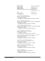
Where to Find it - Online and Printed Information:
System installation (hardware/software) ............VXIbus Configuration Guide
(Supplied with Agilent Command Modules , Embedded Controllers, and VXLink.)
Module configuration and wiring .......................This Manual
SCPI programming .............................................This Manual
SCPI example programs .....................................This Manual, Driver Disk
SCPI command reference ..................................This Manual
Register-Based Programming.............................This Manual
VXIplug&play programming ............................VXIplug&play Online Help
VXIplug&play example programs .....................VXIplug&play Online Help
VXIplug&play function reference......................VXIplug&play Online Help
Soft Front Panel information ..............................VXIplug&play Online Help
VISA language information................................Agilent VISA User's Guide
Agilent VEE programming information.............Agilent VEE User's Manual
*E8462-90000*
Manual Part Number: E8462-90000
Printed in Malaysia E0912
x
Contents
Agilent E8462A 256-Channel Relay Multiplexer
Edition 1
WARRANTY STATEMENT....................................................................................... 5
Safety Symbols ............................................................................................................. 6
WARNINGS................................................................................................................. 6
Declaration of Conformity............................................................................................ 7
User Notes..................................................................................................................... 8
Chapter 1
Configuring the Agilent E8462A Multiplexer ........................................................... 11
Using This Chapter ..................................................................................................... 11
Module Description .................................................................................................... 11
Relay Organization .............................................................................................. 11
Analog Bus .......................................................................................................... 12
Optional Terminal Cards ..................................................................................... 12
Warnings and Cautions............................................................................................... 14
Configuring the Multiplexer Module.......................................................................... 15
Setting the Logical Address ................................................................................ 15
Setting the Interrupt Priority Line ....................................................................... 16
Protection Resistors ............................................................................................. 16
Installing the Multiplexer in a Mainframe .................................................................. 17
Connecting Field Wiring ............................................................................................ 18
Field Wiring
Not Using Optional Terminal Cards .................................................................. 18
Field Wiring Terminal Connector ....................................................................... 18
Front Panel Connector Pin-Out ........................................................................... 19
Connecting the Analog Bus ................................................................................. 23
Terminal Cards .................................................................................................... 24
Programming the Multiplexer..................................................................................... 29
Specifying SCPI Commands ............................................................................... 29
Channel Address ................................................................................................. 29
Card Numbers ..................................................................................................... 30
Channel Numbers, Ranges, and Lists .................................................................. 31
Initial Operation .......................................................................................................... 32
Example: Reset, Self Test, Module ID, and Close Channel .............................. 33
Chapter 2
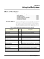
Using the Multiplexer .................................................................................................. 35
What’s in This Chapter ............................................................................................... 35
Reset Conditions ................................................................................................. 35
Switching or Scanning ................................................................................................ 36
Switching Channels to the Analog Bus ............................................................... 36
Mode: WIRE1 ..................................................................................................... 38
Mode: WIRE2 ..................................................................................................... 39
Mode: WIRE3 and WIRE4 ................................................................................. 40
Other Modes ............................................................................................................... 40
Mode: WIRE1x2 and WIRE2x2 ......................................................................... 42
Agilent E8462A User’s Manual Contents
1
Mode: WIRE1x4, WIRE2x4,
WIRE4x2 ............................................................................................................ 43
Mode: WIRE1x8, WIRE2x8,
WIRE4x4 ............................................................................................................ 44
Scanning Channels...................................................................................................... 45
Recalling and Saving States........................................................................................ 52
Saving States ....................................................................................................... 52
Recalling States ................................................................................................... 52
Detecting Error Conditions ......................................................................................... 53
Using Interrupts With Error Checking ................................................................ 53
Analog Bus
2-Wire Resistance Measurements ....................................................................... 53
Routing Relay Operation ..................................................................................... 54
Function Mode Topologies......................................................................................... 54
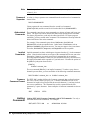
Chapter 3
Agilent E8462A Relay Multiplexer Command Reference ....................................... 67
Using This Chapter ..................................................................................................... 67
Command Types ......................................................................................................... 67
Common Command Format ................................................................................ 67
SCPI Command Format ...................................................................................... 67
Linking Commands ............................................................................................. 68
Parameters ........................................................................................................... 69
SCPI Command Reference ......................................................................................... 70
ABORt ........................................................................................................................ 71
ARM ........................................................................................................................... 72
ARM:COUNT ..................................................................................................... 72
ARM:COUNt? .................................................................................................... 72
DIAGnostic................................................................................................................. 74
DIAGnostic:FUSE? ............................................................................................. 74
DIAGnostic:INTerrupt[:LINE] ........................................................................... 75
DIAGnostic:INTerrupt[:LINE]? ......................................................................... 75
DIAGnostic:INTerrupt:TIMer ............................................................................ 76
DIAGnostic:INTerrupt:TIMer? ........................................................................... 76
DIAGnostic:SCAN:DELay ................................................................................. 77
DIAGnostic:SCAN:DELay? ............................................................................... 77
DISPlay....................................................................................................................... 78
DISPlay:MONitor:CARD ................................................................................... 78
DISPlay:MONitor:CARD? ................................................................................. 78
DISPlay:MONitor[:STATe] ................................................................................ 79
DISPlay:MONitor[:STATe]? .............................................................................. 80
INITiate....................................................................................................................... 81
INITiate:CONTinuous ........................................................................................ 81
INITiate:CONTinuous? ....................................................................................... 82
INITiate[:IMMediate] ......................................................................................... 82
OUTPut....................................................................................................................... 83
OUTPut:ECLTrgn[:STATe] ............................................................................... 83
OUTPut:ECLTrgn[:STATe]? .............................................................................. 84
2
Agilent E8462A User’s Manual Contents
OUTPut[:EXTernal][:STATe] ............................................................................ 84
OUTPut[:EXTernal][:STATe]? .......................................................................... 85
OUTPut:TTLTrgn[:STATe] ................................................................................ 85
OUTPut:TTLTrgn[:STATe]? .............................................................................. 86
[ROUTe:] .................................................................................................................... 87
[ROUTe:]CLOSe ................................................................................................ 87
[ROUTe:]CLOSe? ............................................................................................... 90
[ROUTe:]FUNCtion ............................................................................................ 90
[ROUTe:]FUNCtion? .......................................................................................... 92
[ROUTe:]OPEN .................................................................................................. 92
[ROUTe:]OPEN? ................................................................................................ 95
[ROUTe:]SCAN .................................................................................................. 96
[ROUTe:]SCAN:MODE ..................................................................................... 98
[ROUTe:]SCAN:MODE? ................................................................................... 99
[ROUTe:]SCAN:PORT ...................................................................................... 99
[ROUTe:]SCAN:PORT? ................................................................................... 100
STATus..................................................................................................................... 101
STATus:OPERation:CONDition? .................................................................... 103
STATus:OPERation:ENABle ........................................................................... 103
Comments .......................................................................................................... 103
STATus:OPERation:ENABle? ......................................................................... 103
STATus:OPERation[:EVENt]? ......................................................................... 103
STATus:PRESet ................................................................................................ 104
SYSTem.................................................................................................................... 105
SYSTem:CDEScription? ................................................................................... 105
SYSTem:CPON ................................................................................................ 106
SYSTem:CTYPe? ............................................................................................. 106
SYSTem:ERRor? .............................................................................................. 107
TEST......................................................................................................................... 108
TEST:NUMBer? ............................................................................................... 108
TRIGger .................................................................................................................... 110
TRIGger[:IMMediate] ....................................................................................... 110
TRIGger:SLOPe ................................................................................................ 110
TRIGger:SLOPe? .............................................................................................. 111
TRIGger:SOURce ............................................................................................. 111
TRIGger:SOURce? ........................................................................................... 113
IEEE 488.2 Common Command Reference ............................................................. 114
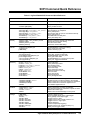
SCPI Command Quick Reference ............................................................................ 115
Chapter 4
Agilent E8462A Scanning Voltmeter Application Examples ................................. 117
Using This Chapter ................................................................................................... 117
Reset Conditions ....................................................................................................... 118
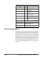
The Scanning Voltmeter ........................................................................................... 119
Making Measurements.............................................................................................. 120
Scanning Voltmeter Measurement Program ..................................................... 120
Voltage Measurements .................................................................................. 121
2-Wire Ohms Measurements ............................................................................. 121
Agilent E8462A User’s Manual Contents
3
4-Wire Ohms Measurements ............................................................................. 121
Scanning Voltmeter Command Quick Reference..................................................... 122
Appendix A
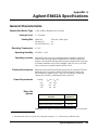
Agilent E8462A Specifications .................................................................................. 125
General Characteristics ............................................................................................. 125
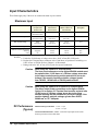
Input Characteristics ................................................................................................. 126
Maximum Input ................................................................................................. 126
DC Performance
(Typical) ............................................................................................................ 126
AC Performance
(Typical) ............................................................................................................ 127
Relay Life .......................................................................................................... 128
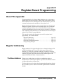
Appendix B
Register-Based Programming ................................................................................... 129
About This Appendix................................................................................................ 129
Register Addressing .................................................................................................. 129
The Base Address .............................................................................................. 129
Register Offset ................................................................................................... 132
Register Descriptions ................................................................................................ 133
ID Register ........................................................................................................ 134
Device Type Register ........................................................................................ 134
Status/Control Register ..................................................................................... 134
Relay Control Registers .................................................................................... 136
Timer Control Register ...................................................................................... 138
Program Timing and Execution ................................................................................ 139
Closing Channels ............................................................................................... 139
Using a Multimeter with the Multiplexer .......................................................... 140
Programming Example ............................................................................................. 141
System Configuration ........................................................................................ 141
Example Program .............................................................................................. 141
Appendix C
Error Messages .......................................................................................................... 145
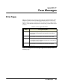
Error Types ............................................................................................................... 145
4
Agilent E8462A User’s Manual Contents
Certification
Agilent Technologies, Inc. certifies that this product met its published specifications at the time of shipment from the factory. Agilent
Technologies further certifies that its calibration measurements are traceable to the United States National Institute of Standards and
Technology (formerly National Bureau of Standards), to the extent allowed by that organization's calibration facility, and to the
calibration facilities of other International Standards Organization members.
AGILENT TECHNOLOGIES WARRANTY STATEMENT
PRODUCT: E8462A
DURATION OF WARRANTY: 1 year
1. Agilent warrants Agilent hardware, accessories and supplies against defects in materials and workmanship for the period specified
above. If Agilent receives notice of such defects during the warranty period, Agilent will, at its option, either repair or replace products
which prove to be defective. Replacement products may be either new or like-new.
2. Agilent warrants that Agilent software will not fail to execute its programming instructions, for the period specified above, due to
defects in material and workmanship when properly installed and used. If Agilent receives notice of such defects during the warranty
period, Agilent will replace software media which does not execute its programming instructions due to such defects.
3. Agilent does not warrant that the operation of Agilent products will be interrupted or error free. If Agilent is unable, within a reasonable
time, to repair or replace any product to a condition as warranted, customer will be entitled to a refund of the purchase price upon prompt
return of the product.
4. Agilent products may contain remanufactured parts equivalent to new in performance or may have been subject to incidental use.
5. The warranty period begins on the date of delivery or on the date of installation if installed by Agilent. If customer schedules or delays
Agilent installation more than 30 days after delivery, warranty begins on the 31st day from delivery.
6. Warranty does not apply to defects resulting from (a) improper or inadequate maintenance or calibration, (b) software, interfacing, parts
or supplies not supplied by Agilent Technologies, (c) unauthorized modification or misuse, (d) operation outside of the published
environmental specifications for the product, or (e) improper site preparation or maintenance.
7. TO THE EXTENT ALLOWED BY LOCAL LAW, THE ABOVE WARRANTIES ARE EXCLUSIVE AND NO OTHER
WARRANTY OR CONDITION, WHETHER WRITTEN OR ORAL, IS EXPRESSED OR IMPLIED AND AGILENT
SPECIFICALLY DISCLAIMS ANY IMPLIED WARRANTY OR CONDITIONS OF MERCHANTABILITY, SATISFACTORY
QUALITY, AND FITNESS FOR A PARTICULAR PURPOSE.
8. Agilent will be liable for damage to tangible property per incident up to the greater of $300,000 or the actual amount paid for the product
that is the subject of the claim, and for damages for bodily injury or death, to the extent that all such damages are determined by a court
of competent jurisdiction to have been directly caused by a defective Agilent product.
9. TO THE EXTENT ALLOWED BY LOCAL LAW, THE REMEDIES IN THIS WARRANTY STATEMENT ARE CUSTOMER’S
SOLE AND EXLUSIVE REMEDIES. EXCEPT AS INDICATED ABOVE, IN NO EVENT WILL AGILENT OR ITS SUPPLIERS BE
LIABLE FOR LOSS OF DATA OR FOR DIRECT, SPECIAL, INCIDENTAL, CONSEQUENTIAL (INCLUDING LOST PROFIT OR
DATA), OR OTHER DAMAGE, WHETHER BASED IN CONTRACT, TORT, OR OTHERWISE.
FOR CONSUMER TRANSACTIONS IN AUSTRALIA AND NEW ZEALAND: THE WARRANTY TERMS CONTAINED IN THIS
STATEMENT, EXCEPT TO THE EXTENT LAWFULLY PERMITTED, DO NOT EXCLUDE, RESTRICT OR MODIFY AND ARE
IN ADDITION TO THE MANDATORY STATUTORY RIGHTS APPLICABLE TO THE SALE OF THIS PRODUCT TO YOU.
U.S. Government Restricted Rights
The Software and Documentation have been developed entirely at private expense. They are delivered and licensed as "commercial
computer software" as defined in DFARS 252.227- 7013 (Oct 1988), DFARS 252.211-7015 (May 1991) or DFARS 252.227-7014 (Jun
1995), as a "commercial item" as defined in FAR 2.101(a), or as "Restricted computer software" as defined in FAR 52.227-19 (Jun
1987)(or any equivalent agency regulation or contract clause), whichever is applicable. You have only those rights provided for such
Software and Documentation by the applicable FAR or DFARS clause or the Agilent standard software agreement for the product
involved.
IEC Measurement Category II Overvoltage Protection
This is a measurement Category II product designed for measurements at voltages up to 300V from earth, including measurements of
voltages at typical mains socket outlets. The product should not be used to make voltage measurements on a fixed electrical installation
including building wiring, circuit breakers, or service panels.
E8462A 256-Channel Relay Multiplexer User Manual
Edition 1 Rev 3
Copyright © 1998-2006 Agilent Technologies, Inc. All Rights Reserved.
5
Documentation History
All Editions and Updates of this manual and their creation date are listed below. The first Edition of the manual is Edition 1. The Edition
number increments by 1 whenever the manual is revised. Updates, which are issued between Editions, contain replacement pages to
correct or add additional information to the current Edition of the manual. Whenever a new Edition is created, it will contain all of the
Update information for the previous Edition. Each new Edition or Update also includes a revised copy of this documentation history page.
Edition 1 (E8462-90000) . . . . . . . . . . . . . . . . . . . . . April 1998
Edition 1 Rev 2 (E8462-90000). . . . . . . . . . . . . . . . .May 2006
Edition 1 Rev 3 (E8462-90000). . . . . . . . . . . . September 2012
Trademarks
Microsoft® is a U.S. registered trademark of Microsoft Corporation
Windows NT® is a U.S. registered trademark of Microsoft Corporation
Windows® and MS Windows® are U.S. registered trademarks of Microsoft Corporation are U.S. registered trademarks of Microsoft
Corp.
Safety Symbols
Instruction manual symbol affixed to
product. Indicates that the user must refer to
the manual for specific WARNING or
CAUTION information to avoid personal
injury or damage to the product.
Alternating current (AC)
Direct current (DC).
Indicates hazardous voltages.
Indicates the field wiring terminal that must
be connected to earth ground before
operating the equipment—protects against
electrical shock in case of fault.
or
Frame or chassis ground terminal—typically
connects to the equipment's metal frame.
Calls attention to a procedure, practice, or
WARNING condition that could cause bodily injury or
death.
Calls attention to a procedure, practice, or
CAUTION condition that could possibly cause damage to
equipment or permanent loss of data.
WARNINGS
The following general safety precautions must be observed during all phases of operation, service, and repair of this product. Failure to
comply with these precautions or with specific warnings elsewhere in this manual violates safety standards of design, manufacture, and
intended use of the product. Agilent Technologies, Inc. assumes no liability for the customer's failure to comply with these requirements.
Ground the equipment: For Safety Class 1 equipment (equipment having a protective earth terminal), an uninterruptible safety earth
ground must be provided from the mains power source to the product input wiring terminals or supplied power cable.
DO NOT operate the product in an explosive atmosphere or in the presence of flammable gases or fumes.
For continued protection against fire, replace the line fuse(s) only with fuse(s) of the same voltage and current rating and type. DO NOT
use repaired fuses or short-circuited fuse holders.
Keep away from live circuits: Operating personnel must not remove equipment covers or shields. Procedures involving the removal of
covers or shields are for use by service-trained personnel only. Under certain conditions, dangerous voltages may exist even with the
equipment switched off. To avoid dangerous electrical shock, DO NOT perform procedures involving cover or shield removal unless you
are qualified to do so.
DO NOT operate damaged equipment: Whenever it is possible that the safety protection features built into this product have been
impaired, either through physical damage, excessive moisture, or any other reason, REMOVE POWER and do not use the product until
safe operation can be verified by service-trained personnel. If necessary, return the product to an Agilent Technologies Sales and Service
Office for service and repair to ensure that safety features are maintained.
DO NOT service or adjust alone: Do not attempt internal service or adjustment unless another person, capable of rendering first aid and
resuscitation, is present.
DO NOT substitute parts or modify equipment: Because of the danger of introducing additional hazards, do not install substitute parts
or perform any unauthorized modification to the product. Return the product to an Agilent Technologies Sales and Service Office for
service and repair to ensure that safety features are maintained.
6
Declaration of Conformity
Declarations of Conformity for this product and for other Agilent products may be downloaded from the Internet. There are
two methods to obtain the Declaration of Conformity:
• Go to http://regulations.corporate.agilent.com/DoC/search.htm. You can then search by product number to find
the latest Declaration of Conformity.
• Alternately, you can go to the product web page (www.agilent.com/find/E8462A), click on the Document
Library tab then scroll down until you find the Declaration of Conformity link.
7
Notes:
8
Notes:
9
Notes:
10
Chapter 1
Configuring the Agilent E8462A Multiplexer
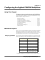
Using This Chapter
This chapter provides general module information, vital WARNINGS and
CAUTIONS, and the tasks you must perform to configure and install the
Agilent E8462A Relay Multiplexer. It also provides information to verify
module installation. Chapter contents are:
• Module Description. . . . . . . . . . . . . . . . . . . . . . . . . . . . . . . .
• Warnings and Cautions . . . . . . . . . . . . . . . . . . . . . . . . . . . . .
• Configuring the Multiplexer Module . . . . . . . . . . . . . . . . . .
• Installing the Multiplexer in a Mainframe . . . . . . . . . . . . . .
• Connecting Field Wiring. . . . . . . . . . . . . . . . . . . . . . . . . . . .
• Terminal Cards . . . . . . . . . . . . . . . . . . . . . . . . . . . . . . . . . . .
• Programming the Multiplexer . . . . . . . . . . . . . . . . . . . . . . . .
• Initial Operation . . . . . . . . . . . . . . . . . . . . . . . . . . . . . . . . . .
Page 11
Page 12
Page 15
Page 17
Page 18
Page 24
Page 29
Page 32
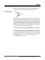
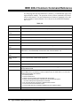
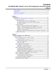
Module Description
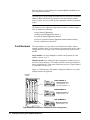
Figure 1-1 shows the Agilent E8462A armature relay multiplexer simplified
block diagram, Option 014 or 015 Terminal Card, and a simple measurement application. Notice the sixteen 100 protection resistors; one in series
with each bank line. Refer to Figure 1-1 for the following description.
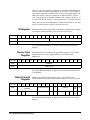
Relay Organization
The 256 channels of the E8462A Relay Multiplexer are organized into eight
banks with 32 channels per bank. The channels in each bank are as follows:
Bank
Channels
0
000 - 015 and 032 - 047
1
016 - 031 and 048 - 063
2
064 - 079 and 096 - 111
3
080 - 095 and 112 - 127
4
128 - 143 and 160 - 175
5
144 - 159 and 176 - 191
6
192 - 207 and 224 - 239
7
208 - 223 and 240 - 255
The default configuration is 128 channels of 2-wire switches (128 x 2).
Configuring the Agilent E8462A Multiplexer
11
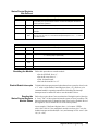
Tree relays T0 through T21 (Channel 9000 through Channel 9021) configure the module to the desired operating mode: 1-wire, 2-wire, 3-wire or
4-wire mode. You use the tree relays to manually configure this module in
one of the following configurations (or in a combination of these configurations). Using the ROUTe:FUNCtion command sets the tree switches
automatically for any one of the following configurations (e.g., 2-64x2).
Quantity
Switch Topology
1
256 x 1or
128 x 2 or
64 x 3 or
64 x 4
2
128 x 1 or
64 x 2 or
32 x 4
4
64 x 1 or
32 x 2 or
16 x 4
8
32 x 1 or
16 x 2
Relays AB200 through AB204 (Channels 9200 through 9204) are the analog
bus connection control relays which connect the terminal busses to the front
panel analog bus connector.
Analog Bus
Optional Terminal
Cards
The “Analog Bus Front Panel Connector” on the module allows you to
connect this Multiplexer to to a VXI Multimeter (such as the Agilent
E1411B and/or E1326B) directly. Either of these Multimeter’s allow you to
configure the Multimeter and one or more E8462A Multiplexers in a
“Scanning Voltmeter” configuration. See Chapter 4 for information on
using the E8462A in a scanning voltmeter.
The E8462A has three optional terminal cards which you may purchase
from Agilent Technologies:
• Option 012 Crimp & Insert Terminal Card is provided with the same
terminal connector described above but does not provide the
crimp-and-insert contacts. Additionally, you must order the quantity of
contacts your application requires. This terminal card provides strain
relief and a housing to protect the contacts. Refer to Option 012
Crimp-and- Insert Terminal Block on page 24.
• Option 014 Fault Tolerant Terminal Card and Option 015 Ribbon
Cable Terminal Card provides nine ribbon-cable header connectors
(P101-P109). P101 through P108 contain 16 terminals (Ter0 through
Ter15) and all the 256 channels (CH000-CH255) and P109 is the
analog bus connector. Option 014 has PTC resistors; Option 015 does
not. Refer to Option 014 Fault Tolerant Terminal Block on page 24.
12
Configuring the Agilent E8462A Multiplexer
Figure 1-1. Agilent E8462A Simplified Schematic
Configuring the Agilent E8462A Multiplexer
13
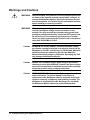
Warnings and Cautions
14
WARNING
SHOCK HAZARD. Only qualified, service-trained personnel who
are aware of the hazards involved should install, configure, or
remove the Multiplexer Module. Disconnect all power sources
from the mainframe, the Terminal Cards, and installed modules
before installing or removing a module.
WARNING
When handling user wiring connected to the Terminal Card,
consider the highest voltage present accessible on any
terminal. Use only wire with an insulation rating greater than
the highest voltage which will be present on the Terminal Card.
Do not touch any circuit element connected to the Terminal
Card if any other connector to the Terminal Card is energized to
more than 30VACRMS or 60VDC.
Caution
MAXIMUM VOLTAGE/CURRENT. Maximum allowable voltage
per channel, terminal-to-terminal or terminal-to-chassis for the
Multiplexer is 200 VDC, 140 VACrms, or 200VACpeak. Maximum
switching current per channel is 500 mA (non-inductive).
Maximum transient voltage is 1200V peak. Exceeding any limit
may damage the Multiplexer Module.
Caution
WIRING THE TERMINAL CARD. When wiring to the terminal
connectors on the Agilent E8462A Terminal Card, be sure not to
exceed a 5mm strip back of insulation to prevent the possibility
of shorting to other wiring on adjacent terminals.
Caution
STATIC ELECTRICITY. Static electricity is a major cause of
component failure. To prevent damage to the electrical
components in the Multiplexer, observe anti-static techniques
whenever removing, configuring, and installing a module. The
Multiplexer is susceptible to static discharges. Do not install
the Multiplexer Module without its metal shield attached.
Configuring the Agilent E8462A Multiplexer
Configuring the Multiplexer Module
The Multiplexer module can be configured to the operating modes through
the VXIplug&play driver or via SCPI commands. These drivers are located
on the supplied CD-ROM. Before installing the module into a VXIbus
mainframe (e.g. Agilent E1401A), you need to set the Multiplexer’s logical
address.
Setting the Logical
Address
The factory default logical address switch setting is 112. Valid addresses are
from 1 to 254 for static configuration and address 255 for dynamic
configuration. The Agilent E8462A supports dynamic configuration of the
address. This means the address is set programmatically by the resource
manager when it encounters a module with address 255.
The logical address must be a multiple of eight (e.g., 112, 120, 128, etc.)
when using a VXIbus command module. An instrument must have a unique
secondary address which is the logical address divided by eight. When
multiple modules are used for form a “switchbox”, the logical addresses
must be sequential with the first module address being a multiple of eight.
See Figure 1-13. "Card Numbers in a Multiple-module Configuration" on
page 30 for more information.
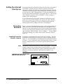
Refer to the C-Size VXIbus System Installation and Getting Started Guide
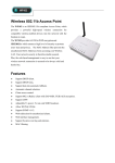
for addressing information. Figure 1-2 shows the logical address switch
position. You access the address switch through the air hole on the edge of
the module. The label on the side cover identifies the switch location.
Logical Address Switch
Factory default setting = 112
Figure 1-2. Setting the Logical Address
Configuring the Agilent E8462A Multiplexer
15
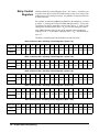
Setting the Interrupt
Priority Line
For most applications the default priority line should not have to be changed.
An interrupt is generated after any channel is opened or closed when
interrupts are enabled. The interrupt is generated approximately 5 ms after
command execution allowing for relay settling time. The interrupt line can
be set to any one of the VXI backplane lines 1-7 through writing the bits 10,
9 and 8 of the Status/Control Register. The default value is 1. The interrupt
can be disabled at power-up, after a SYSRESET, or after resetting the
module via the Control Register.
See the DIAGnostic:INTerrupt[:LINE] command for setting the interrupt
priority line using a SCPI command. See Appendix B, Agilent E8462A
Register-Based Programming, for more information about setting the
interrupt priority line by writing to the Status/Control Register.
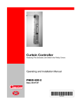
Protection
Resistors
Figure 1-1 shows the 100 protection resistors in series with each bank line.
These protection resistors limit the maximum current through the relays.
However, in some measurements (such as 2-Wire resistance measurements)
you may want to bypass the protection resistors. Each resistor has a jumper
(J601 for Bank 0, JP602 for Bank 1, JP 603 for Bank2, . . . JP616 for Bank
15) across it allowing you to short out the resistor if necessary. Refer to
Figure 1-3.
Installing Protection
Resistor Jumpers
The module is shipped from the factory with a bag of jumpers. You must
install these on the E8462A PC board in one of the two settings shown in
Figure 1-3. It is recommended you install them in the default position shown
in Figure 1-3 if your application requires 100 protection resistors. Install
them over both jumper pins if you want to bypass the 100 protection
resistors.
Note
The module is shipped from the factory with a bag of jumpers. You should
load these jumpers in the default position as shown in Figure 1-3 if your
application requires 100 protection resistors. Install the jumpers across
both pins if you do not require the 100 protection resistors in your
application.
JUMPERS ARE SUPPLIED IN A BAG
AND MUST BE INSTALLED
=
(default)
=
Figure 1-3. Protection Resistors and Jumpers
16
Configuring the Agilent E8462A Multiplexer
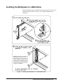
Installing the Multiplexer in a Mainframe
The Agilent E8462A may be installed in any slot (except slot 0) in a C-size
VXIbus mainframe. Refer to Figure 1-4 to install the Multiplexer in a
mainframe.
NOTE: The extraction levers will not seat
the backplane connectors on older
VXIbus mainframes. You must manually
seat the connectors by pushing in the
module until the module’s front panel is
flush with the front of the mainframe. The
extraction levers may be used to guide
or remove the multiplexer.
Figure 1-4. Installing the Multiplexer in a VXIbus Mainframe
Configuring the Agilent E8462A Multiplexer
17
Connecting Field Wiring
Field Wiring
Not Using Optional
Terminal Cards
The E8462A IS NOT supplied with a terminal card or connectors. You may
purchase 160-pin terminal connectors, necessary crimp-and-insert contacts
and the required crimp tool from Agilent Technologies or directly from the
manufacturer, ERNI Components1 (see Table 1-1 below).
Table 1-1. You Must Purchase Connectors, Contacts and Tools.
Manufacturer
Agilent Tecnologies
ERNI Components1
Field Wiring
Terminal Connector
Caution
Component
Connector P/N
160-pin connector
1252-6531
one (1) crimp-andinsert contact
1252-6533
one (1) crimp-andinsert contact single
conductor assembly
(see Figure 1-5)
required crimp tool
8710-2306
disassembly tool
(optional)
8710-2307
160-pin connector
024070
one (1) crimp-andinsert contact
014728
required crimp tool
014374
disassembly tool
(optional)
471555
8150-5207
Refer to Table 1-1 and Figure 1-5. You can purchase 160-pin field wiring
terminal connectors (two are required, order Agilent P/N 1252-6531 or order
direct from the manufacturer, ERNI Components, P/N 024070) and the
necessary crimp-and-insert contacts (Agilent single contact P/N is 12526533, or ERNI P/N 014728). The contacts are gold-plated, accept a wire size
of 20 to 26AWG, and carry a maximum current of 2A @70°C. You will also
need a crimp tool (Agilent P/N 8710-2306 or ERNI P/N 014374) and optionally a disassembly tool (Agilent P/N 8710-2307 or ERNI P/N 471555).
Due to the close terminal spacing and the potential for pin-topin leakage, the terminal connector blocks on the Option 012
Crimp-and-Insert Terminal Card must be replaced after 15,000
hours of voltage stress if the module regularly switches
voltages greater than 60VDC, 50VACrms, or 70.7 VACpeak.
1. Contact ERNI Components, A Division of ODIN Components, Inc., 520 Southlake Blvd., Richmond, VA
23236, U.S.A. Telephone, (804) 794-6367, FAX (804) 379-2109.
18
Configuring the Agilent E8462A Multiplexer
A single-conductor with contact (a crimp-and-insert contact is crimped onto
one end, the other end is not terminated) is available as Agilent P/N
8150-5207.
Length: 2 meters
Wire Gauge: 24 AWG
Insulation Rating: 105 C maximum
Voltage: 250 V maximum
Figure 1-5. Connector Block and Single-Conductor Wire with Contact (not provided).
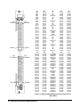
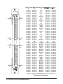
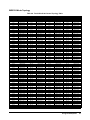
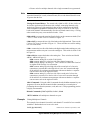
Front Panel
Connector Pin-Out
Note
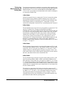
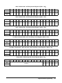
Figure 1-6 shows the Multiplexer's front panel and the connector pin-out.
The Agilent E8462A is not supplied with terminal connectors, field wiring
contacts or terminal cards. However, terminal cards can be ordered as an
option.
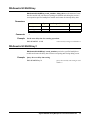
In Figure 1-6, columns C1 and C2 contain the terminals for the 16-line
multiplexer bus (Ter0 to Ter15) as well as terminals for T_ACCESS* and
T_ERROR*. Ter0 to Ter15 refer to Terminal 0 through Terminal 15.
T_ACCESS* and T_ERROR* are two signals to drive LEDs on the Option
012 Terminal Card. “NC” refers to “Not Connected” and “CGND” refers to
“Chassis Ground”.
Configuring the Agilent E8462A Multiplexer
19
A1
CH000
E1
CH096
CH031
CH127
A2
CH128
E2
CH224
CH159
CH255
A1
CH 0
CH 1
CH 2
CH 3
CH 4
CH 5
CH 6
CH 7
CH 8
CH 9
CH 10
CH 11
CH 12
CH 13
CH 14
CH 15
CH 16
CH 17
CH 18
CH 19
CH 20
CH 21
CH 22
CH 23
CH 24
CH 25
CH 26
CH 27
CH 28
CH 29
CH 30
CH 31
B1
CH 32
CH 33
CH 34
CH 35
CH 36
CH 37
CH 38
CH 39
CH 40
CH 41
CH 42
CH 43
CH 44
CH 45
CH 46
CH 47
CH 48
CH 49
CH 50
CH 51
CH 52
CH 53
CH 54
CH 55
CH 56
CH 57
CH 58
CH 59
CH 60
CH 61
CH 62
CH 63
C1
NC
NC
NC
Terminal 0
NC
H1
NC
Terminal 1
NC
NC
NC
Terminal 2
NC
L1
NC
Terminal 3
CGND
CGND
CGND
Terminal 4
NC
L2
NC
Terminal 5
NC
G
NC
Terminal 6
NC
H2
NC
Terminal 7
D1
CH 64
CH 65
CH 66
CH 67
CH 68
CH 69
CH 70
CH 71
CH 72
CH 73
CH 74
CH 75
CH 76
CH 77
CH 78
CH 79
CH 80
CH 81
CH 82
CH 83
CH 84
CH 85
CH 86
CH 87
CH 88
CH 89
CH 90
CH 91
CH 92
CH 93
CH 94
CH 95
E1
CH 96
CH 97
CH 98
CH 99
CH 100
CH 101
CH 102
CH 103
CH 104
CH 105
CH 106
CH 107
CH 108
CH 109
CH 110
CH 111
CH 112
CH 113
CH 114
CH 115
CH 116
CH 117
CH 118
CH 119
CH 120
CH 121
CH 122
CH 123
CH 124
CH 125
CH 126
CH 127
A2
CH 128
CH 129
CH 130
CH 131
CH 132
CH 133
CH 134
CH 135
CH 136
CH 137
CH 138
CH 139
CH 140
CH 141
CH 142
CH 143
CH 144
CH 145
CH 146
CH 147
CH 148
CH 149
CH 150
CH 151
CH 152
CH 153
CH 154
CH 155
CH 156
CH 157
CH 158
CH 159
B2
CH 160
CH 161
CH 162
CH 163
CH 164
CH 165
CH 166
CH 167
CH 168
CH 169
CH 170
CH 171
CH 172
CH 173
CH 174
CH 175
CH 176
CH 177
CH 178
CH 179
CH 180
CH 181
CH 182
CH 183
CH 184
CH 185
CH 186
CH 187
CH 188
CH 189
CH 190
CH 191
C2
T_ACCESS*
T_ERROR*
Reserved
Terminal 8
Reserved
XVCC
Reserved
Terminal 9
Reserved
Reserved
Reserved
Terminal 10
NC
NC
Reserved
Terminal 11
CGND
CGND
CGND
Terminal 12
Reserved
Reserved
Reserved
Terminal 13
Reserved
Reserved
Reserved
Terminal 14
Reserved
Reserved
Reserved
Terminal 15
D2
CH 192
CH 193
CH 194
CH 195
CH 196
CH 197
CH 198
CH 199
CH 200
CH 201
CH 202
CH 203
CH 204
CH 205
CH 206
CH 207
CH 208
CH 209
CH 210
CH 211
CH 212
CH 213
CH 214
CH 215
CH 216
CH 217
CH 218
CH 219
CH 220
CH 221
CH 222
CH 223
E2
CH 224
CH 225
CH 226
CH 227
CH 228
CH 229
CH 230
CH 231
CH 232
CH 233
CH 234
CH 235
CH 236
CH 237
CH 238
CH 239
CH 240
CH 241
CH 242
CH 243
CH 244
CH 245
CH 246
CH 247
CH 248
CH 249
CH 250
CH 251
CH 252
CH 253
CH 254
CH 255
Figure 1-6. Agilent E8462A Multiplexer Front Panel Pin-out
1-Wire Mode
20
Configuring the Agilent E8462A Multiplexer
A1
CH000
HI
E1
CH032
HI
CH031
HI
CH063
HI
A2
CH064
HI
E2
CH096
HI
CH095
HI
CH127
HI
A1
CH 0 HI
CH 1 HI
CH 2 HI
CH 3 HI
CH 4 HI
CH 5 HI
CH 6 HI
CH 7 HI
CH 8 HI
CH 9 HI
CH 10 HI
CH 11 HI
CH 12 HI
CH 13 HI
CH 14 HI
CH 15 HI
CH 16 HI
CH 17 HI
CH 18 HI
CH 19 HI
CH 20 HI
CH 21 HI
CH 22 HI
CH 23 HI
CH 24 HI
CH 25 HI
CH 26 HI
CH 27 HI
CH 28 HI
CH 29 HI
CH 30 HI
CH 31 HI
B1
CH 0 LO
CH 1 LO
CH 2 LO
CH 3 LO
CH 4 LO
CH 5 LO
CH 6 LO
CH 7 LO
CH 8 LO
CH 9 LO
CH 10 LO
CH 11 LO
CH 12 LO
CH 13 LO
CH 14 LO
CH 15 LO
CH 16 LO
CH 17 LO
CH 18 LO
CH 19 LO
CH 20 LO
CH 21 LO
CH 22 LO
CH 23 LO
CH 24 LO
CH 25 LO
CH 26 LO
CH 27 LO
CH 28 LO
CH 29 LO
CH 30 LO
CH 31 LO
C1
NC
NC
NC
Terminal 0
NC
H1
NC
Terminal 1
NC
NC
NC
Terminal 2
NC
L1
NC
Terminal 3
CGND
CGND
CGND
Terminal 4
NC
L2
NC
Terminal 5
NC
G
NC
Terminal 6
NC
H2
NC
Terminal 7
D1
CH 32 LO
CH 33 LO
CH 34 LO
CH 35 LO
CH 36 LO
CH 37 LO
CH 38 LO
CH 39 LO
CH 40 LO
CH 41 LO
CH 42 LO
CH 43 LO
CH 44 LO
CH 45 LO
CH 46 LO
CH 47 LO
CH 48 LO
CH 49 LO
CH 50 LO
CH 51 LO
CH 52 LO
CH 53 LO
CH 54 LO
CH 55 LO
CH 56 LO
CH 57 LO
CH 58 LO
CH 59 LO
CH 60 LO
CH 61 LO
CH 62 LO
CH 63 LO
E1
CH 32 HI
CH 33 HI
CH 34 HI
CH 35 HI
CH 36 HI
CH 37 HI
CH 38 HI
CH 39 HI
CH 40 HI
CH 41 HI
CH 42 HI
CH 43 HI
CH 44 HI
CH 45 HI
CH 46 HI
CH 47 HI
CH 48 HI
CH 49 HI
CH 50 HI
CH 51 HI
CH 52 HI
CH 53 HI
CH 54 HI
CH 55 HI
CH 56 HI
CH 57 HI
CH 58 HI
CH 59 HI
CH 60 HI
CH 61 HI
CH 62 HI
CH 63 HI
A2
CH 64 HI
CH 65 HI
CH 66 HI
CH 67 HI
CH 68 HI
CH 69 HI
CH 70 HI
CH 71 HI
CH 72 HI
CH 73 HI
CH 74 HI
CH 75 HI
CH 76 HI
CH 77 HI
CH 78 HI
CH 79 HI
CH 80 HI
CH 81 HI
CH 82 HI
CH 83 HI
CH 84 HI
CH 85 HI
CH 86 HI
CH 87 HI
CH 88 HI
CH 89 HI
CH 90 HI
CH 91 HI
CH 92 HI
CH 93 HI
CH 94 HI
CH 95 HI
B2
CH 64 LO
CH 65 LO
CH 66 LO
CH 67 LO
CH 68 LO
CH 69 LO
CH 70 LO
CH 71 LO
CH 72 LO
CH 73 LO
CH 74 LO
CH 75 LO
CH 76 LO
CH 77 LO
CH 78 LO
CH 79 LO
CH 80 LO
CH 81 LO
CH 82 LO
CH 83 LO
CH 84 LO
CH 85 LO
CH 86 LO
CH 87 LO
CH 88 LO
CH 89 LO
CH 90 LO
CH 91 LO
CH 92 LO
CH 93 LO
CH 94 LO
CH 95 LO
C2
T_ACCESS*
T_ERROR*
Reserved
Terminal 8
Reserved
XVCC
Reserved
Terminal 9
Reserved
Reserved
Reserved
Terminal 10
NC
NC
Reserved
Terminal 11
CGND
CGND
CGND
Terminal 12
Reserved
Reserved
Reserved
Terminal 13
Reserved
Reserved
Reserved
Terminal 14
Reserved
Reserved
Reserved
Terminal 15
D2
CH 96 LO
CH 97 LO
CH 98 LO
CH 99 LO
CH 100 LO
CH 101 LO
CH 102 LO
CH 103 LO
CH 104 LO
CH 105 LO
CH 106 LO
CH 107 LO
CH 108 LO
CH 109 LO
CH 110 LO
CH 111 LO
CH 112 LO
CH 113 LO
CH 114 LO
CH 115 LO
CH 116 LO
CH 117 LO
CH 118 LO
CH 119 LO
CH 120 LO
CH 121 LO
CH 122 LO
CH 123 LO
CH 124 LO
CH 125 LO
CH 126 LO
CH 127 LO
E2
CH 96 HI
CH 97 HI
CH 98 HI
CH 99 HI
CH 100 HI
CH 101 HI
CH 102 HI
CH 103 HI
CH 104 HI
CH 105 HI
CH 106 HI
CH 107 HI
CH 108 HI
CH 109 HI
CH 110 HI
CH 111 HI
CH 112 HI
CH 113 HI
CH 114 HI
CH 115 HI
CH 116 HI
CH 117 HI
CH 118 HI
CH 119 HI
CH 120 HI
CH 121 HI
CH 122 HI
CH 123 HI
CH 124 HI
CH 125 HI
CH 126 HI
CH 127 HI
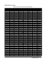
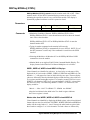
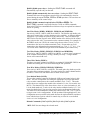
Figure 1-7. Agilent E8462A Multiplexer Front Panel Pin-out
2-Wire Mode
Configuring the Agilent E8462A Multiplexer
21
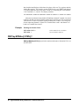
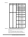
NOTE: 3-Wire Mode does not use the column E connections.
A1
CH000
HI 1
E1
CH000
HI 2
CH031
HI 1
CH031
HI 2
A2
CH032
HI 1
E2
CH032
HI 2
CH063
HI 1
CH063
HI 2
A1
CH 0 HI 1
CH 1 HI 1
CH 2 HI 1
CH 3 HI 1
CH 4 HI 1
CH 5 HI 1
CH 6 HI 1
CH 7 HI 1
CH 8 HI 1
CH 9 HI 1
CH 10 HI 1
CH 11 HI 1
CH 12 HI 1
CH 13 HI 1
CH 14 HI 1
CH 15 HI 1
CH 16 HI 1
CH 17 HI 1
CH 18 HI 1
CH 19 HI 1
CH 20 HI 1
CH 21 HI 1
CH 22 HI 1
CH 23 HI 1
CH 24 HI 1
CH 25 HI 1
CH 26 HI 1
CH 27 HI 1
CH 28 HI 1
CH 29 HI 1
CH 30 HI 1
CH 31 HI 1
B1
CH 0 LO 1
CH 1 LO 1
CH 2 LO 1
CH 3 LO 1
CH 4 LO 1
CH 5 LO 1
CH 6 LO 1
CH 7 LO 1
CH 8 LO 1
CH 9 LO 1
CH 10 LO 1
CH 11 LO 1
CH 12 LO 1
CH 13 LO 1
CH 14 LO 1
CH 15 LO 1
CH 16 LO 1
CH 17 LO 1
CH 18 LO 1
CH 19 LO 1
CH 20 LO 1
CH 21 LO 1
CH 22 LO 1
CH 23 LO 1
CH 24 LO 1
CH 25 LO 1
CH 26 LO 1
CH 27 LO 1
CH 28 LO 1
CH 29 LO 1
CH 30 LO 1
CH 31 LO 1
C1
NC
NC
NC
Terminal 0
NC
H1
NC
Terminal 1
NC
NC
NC
Terminal 2
NC
L1
NC
Terminal 3
CGND
CGND
CGND
Terminal 4
NC
L2
NC
Terminal 5
NC
G
NC
Terminal 6
NC
H2
NC
Terminal 7
D1
CH 0 LO 2
CH 1 LO 2
CH 2 LO 2
CH 3 LO 2
CH 4 LO 2
CH 5 LO 2
CH 6 LO 2
CH 7 LO 2
CH 8 LO 2
CH 9 LO 2
CH 10 LO 2
CH 11 LO 2
CH 12 LO 2
CH 13 LO 2
CH 14 LO 2
CH 15 LO 2
CH 16 LO 2
CH 17 LO 2
CH 18 LO 2
CH 19 LO 2
CH 20 LO 2
CH 21 LO 2
CH 22 LO 2
CH 23 LO 2
CH 24 LO 2
CH 25 LO 2
CH 26 LO 2
CH 27 LO 2
CH 28 LO 2
CH 29 LO 2
CH 30 LO 2
CH 31 LO 2
E1
CH 0 HI 2
CH 1 HI 2
CH 2 HI 2
CH 3 HI 2
CH 4 HI 2
CH 5 HI 2
CH 6 HI 2
CH 7 HI 2
CH 8 HI 2
CH 9 HI 2
CH 10 HI 2
CH 11 HI 2
CH 12 HI 2
CH 13 HI 2
CH 14 HI 2
CH 15 HI 2
CH 16 HI 2
CH 17 HI 2
CH 18 HI 2
CH 19 HI 2
CH 20 HI 2
CH 21 HI 2
CH 22 HI 2
CH 23 HI 2
CH 24 HI 2
CH 25 HI 2
CH 26 HI 2
CH 27 HI 2
CH 28 HI 2
CH 29 HI 2
CH 30 HI 2
CH 31 HI 2
A2
CH 32 HI 1
CH 33 HI 1
CH 34 HI 1
CH 35 HI 1
CH 36 HI 1
CH 37 HI 1
CH 38 HI 1
CH 39 HI 1
CH 40 HI 1
CH 41 HI 1
CH 42 HI 1
CH 43 HI 1
CH 44 HI 1
CH 45 HI 1
CH 46 HI 1
CH 47 HI 1
CH 48 HI 1
CH 49 HI 1
CH 50 HI 1
CH 51 HI 1
CH 52 HI 1
CH 53 HI 1
CH 54 HI 1
CH 55 HI 1
CH 56 HI 1
CH 57 HI 1
CH 58 HI 1
CH 59 HI 1
CH 60 HI 1
CH 61 HI 1
CH 62 HI 1
CH 63 HI 1
B2
CH 32 LO 1
CH 33 LO 1
CH 34 LO 1
CH 35 LO 1
CH 36 LO 1
CH 37 LO 1
CH 38 LO 1
CH 39 LO 1
CH 40 LO 1
CH 41 LO 1
CH 42 LO 1
CH 43 LO 1
CH 44 LO 1
CH 45 LO 1
CH 46 LO 1
CH 47 LO 1
CH 48 LO 1
CH 49 LO 1
CH 50 LO 1
CH 51 LO 1
CH 52 LO 1
CH 53 LO 1
CH 54 LO 1
CH 55 LO 1
CH 56 LO 1
CH 57 LO 1
CH 58 LO 1
CH 59 LO 1
CH 60 LO 1
CH 61 LO 1
CH 62 LO 1
CH 63 LO 1
C2
T_ACCESS*
T_ERROR*
Reserved
Terminal 8
Reserved
XVCC
Reserved
Terminal 9
Reserved
Reserved
Reserved
Terminal 10
NC
NC
Reserved
Terminal 11
CGND
CGND
CGND
Terminal 12
Reserved
Reserved
Reserved
Terminal 13
Reserved
Reserved
Reserved
Terminal 14
Reserved
Reserved
Reserved
Terminal 15
D2
CH 32 LO 2
CH 33 LO 2
CH 34 LO 2
CH 35 LO 2
CH 36 LO 2
CH 37 LO 2
CH 38 LO 2
CH 39 LO 2
CH 40 LO 2
CH 41 LO 2
CH 42 LO 2
CH 43 LO 2
CH 44 LO 2
CH 45 LO 2
CH 46 LO 2
CH 47 LO 2
CH 48 LO 2
CH 49 LO 2
CH 50 LO 2
CH 51 LO 2
CH 52 LO 2
CH 53 LO 2
CH 54 LO 2
CH 55 LO 2
CH 56 LO 2
CH 57 LO 2
CH 58 LO 2
CH 59 LO 2
CH 60 LO 2
CH 61 LO 2
CH 62 LO 2
CH 63 LO 2
E2
CH 32 HI 2
CH 33 HI 2
CH 34 HI 2
CH 35 HI 2
CH 36 HI 2
CH 37 HI 2
CH 38 HI 2
CH 39 HI 2
CH 40 HI 2
CH 41 HI 2
CH 42 HI 2
CH 43 HI 2
CH 44 HI 2
CH 45 HI 2
CH 46 HI 2
CH 47 HI 2
CH 48 HI 2
CH 49 HI 2
CH 50 HI 2
CH 51 HI 2
CH 52 HI 2
CH 53 HI 2
CH 54 HI 2
CH 55 HI 2
CH 56 HI 2
CH 57 HI 2
CH 58 HI 2
CH 59 HI 2
CH 60 HI 2
CH 61 HI 2
CH 62 HI 2
CH 63 HI 2
Figure 1-8. Agilent E8462A Multiplexer Front Panel Pin-out
3-Wire Mode and 4-Wire Mode
22
Configuring the Agilent E8462A Multiplexer
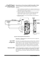
Connecting the
Analog Bus
The analog bus provides a common bus to all switch modules in multiple
switch cards. A multimeter or other instrument can be connected to the
analog bus. Use flat ribbon analog bus cables between Multiplexers and
other Agilent VXI modules that have an analog bus (both C-size modules or
B-size modules in a C-size adapter). Agilent E1411B 5-Digit Multimeter
users (and Agilent E1326B in a C-size adapter) must continue the analog bus
connection between Multiplexers and switch modules to the multimeter in
order to use the scanning and measurement capability the multimeter has to
offer. These cables provide the input to the multimeter from the
multiplexer/switch channels and fit under the Multiplexer’s optional
terminal cards. Refer to Figure 1-9.
Figure 1-9. Agilent E1411B Connections to the Analog Bus
Note
The Option 014 and 015 Terminal Cards distribute the analog bus from
P109 in the Terminal Card. An external measuring device can be connected
to the analog bus through the terminal card's terminals (pin 5 through pin
16 of connector P109). You can connect this Multiplexer to an E1412A
Multimeter, or other instruments not having an analog bus connector, via a
ribbon cable (not supplied). See Option 014 Fault Tolerant Terminal Block
on page 24 (and Option 015 on page 25) for more information.
Note
To use the Agilent E1326B 5½-Digit Multimeter in a C-size adapter:
Use the 19.5 inch analog bus cable part number E1326-61611 for analog
bus connection between the E1326B and the E8462A. The cable described
in Figure 1-9 will be too short for connection to the Agilent E1326B.
WARNING
The Multiplexer inputs must be limited to 30VACrms or 60VDC if
either end of the analog bus is accessible to users (such as on
the front panel of a multimeter).
Configuring the Agilent E8462A Multiplexer
23
Terminal Cards
Three optional terminal cards are available for the Agilent E8462A:
• Option 012 Crimp-and-Insert Terminal Card
• Option 014 Fault Tolerant Terminal Card
• Option 015 Ribbon Cable Connector Terminal Card
Option 012 Crimp-andInsert Terminal Block
Note
The Option 012 Terminal Block provides a terminal card housing and two
160-pin terminal connector blocks (Agilent P/N 1252-6531).
The contacts for the Option 012 Terminal Block connectors ARE NOT
provided. This allows you to purchase only the number of contacts you
require for your application.
Agilent P/N 8150-5207 is available for purchase and is a single-conductor
with contact (a crimp-and-insert contact is crimped onto one end, the other
end is not terminated). Refer to Figure 1-5. "Connector Block and
Single-Conductor Wire with Contact (not provided)." on page 19.
The crimp-and-insert contacts you must purchase (Agilent P/N 1252-6533
for single contact) are gold-plated, accept a wire size of 20 to 26AWG, and
carry a maximum current of 2A @70°C. You will also need a crimp tool
(Agilent P/N 8710-2306 or ERNI Components P/N 014374) and optionally
a disassembly tool (P/N 8710-2307 or ERNI Components P/N 471555).
Caution
The Agilent E8462A Option 012 Crimp-and-Insert Terminal
Block connectors must be replaced after 15,000 hours of use if
the module regularly switches voltages >190VDC or
>190VACrms due to the close terminal spacing and the
potential for pin-to-pin leakage.
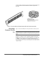
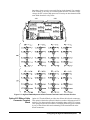
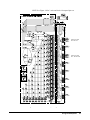
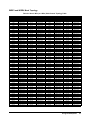
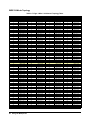
Option 014 Fault Tolerant
Terminal Block
Option 014 Terminal Block provides nine ribbon-cable header connectors.
P101 through P108 provide the channels and terminal bus connection from
the front panel connectors (J101 and J102) of the Agilent E8462A; P109 is
a 16-pin connector for the analog bus connection. DS101 and DS102 are
LEDs which provide information as follows. The green LED (DS101) will
light as the Multiplexer is accessed by the VXI controller. The yellow LED
(DS102) monitors the firmware execution, and will light whenever there is
error during DIAG:TEST? or *TST? command execution.
Caution
The Option 014 Fault Tolerant Terminal Block is limited to
voltages of 60VDC or 50 VACrms or 70.7 VACpeak maximum.
Do not exceed these voltages.
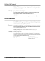
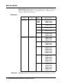
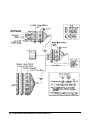
Figure 1-10 shows the associated channel numbers. RT100 through RT355
are 256 PTC1 resistors which behave like a resettable fuse and will increase
1. PTC: Positive Temperature Coefficient.
24
Configuring the Agilent E8462A Multiplexer
impedance when excessive current is flowing in the channel. For example,
if the contacts of one relay are welded together because it switches a large
voltage, the PTC resistors help protect user circuitry on other channels in the
same bank when their relays close.
J101
J102
Figure 1-10. Agilent E8462A Option 014 Fault Tolerant Terminal Card Connector Pin-Out
Option 015 Ribbon Cable
Connector Terminal
Block
Option 015 Terminal Block provides nine ribbon-cable header connectors.
This option is identical to option 014 but does not have fault protection PTC
resistors. Zero ohm resistors (short) are loaded in place of the PTC resistors.
This option provides the convenience of bringing field wiring to the module
by way of flat ribbon cable and terminating on the terminal block at the
header connectors.
Configuring the Agilent E8462A Multiplexer
25
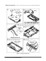
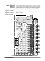
Wiring a Terminal Card
Figure 1-11 shows how to connect wire to the optional terminal blocks.
Figure 1-11. Wiring a Terminal Card
26
Configuring the Agilent E8462A Multiplexer
See Figure 1-12
for more detail.
Mark the last
digit of the MUX
model number
e.g., E8462
Figure 1-11. Wiring a Terminal Card (continued)
Configuring the Agilent E8462A Multiplexer
27
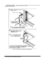
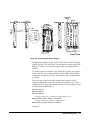
Attaching a Terminal
Block to the Multiplexer
Figure 1-12 shows how to attach an optional terminal block to the Agilent
E8462A Relay Multiplexer module.
Figure 1-12. Attach a Terminal Block to the Multiplexer
28
Configuring the Agilent E8462A Multiplexer
Programming the Multiplexer
To program the Agilent E8462A Multiplexer using SCPI, you must know
the interface and module address and SCPI commands to be used.
Guidelines to select SCPI commands for the Multiplexer follow. See the
Agilent 75000 Series C Installation and Getting Started Guide for interface
addressing.
Note
This discussion applies only to SCPI (Standard Commands for
Programmable Instruments) programming. See Appendix B for
information on the Multiplexer's registers.
Specifying SCPI
Commands
To address specific channels within a Multiplexer, you must specify the
SCPI command and channel address. Use CLOSe <channel_list> to close
the channels specified, OPEN <channel_list> to open the channels
specified, and SCAN <channel_list> to close and open the set of channels
specified, one channel at a time.
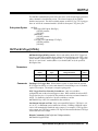
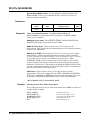
Channel Address
The Multiplexer's channel address (channel_list) has the form (@ccbnnn)
where cc = module (card) number (01-99), b = bank or MUX number (0 to
one less than banks or muxes) and nnn = channel numbers. The channel
number consists of three parts listed in the below table:
Channel List
ssbccc
Card Number
(cc)
01-99
Bank or Mux
(b)
Channel Number
(nnn)
Channel Description
0-7
000-255
256 channel relays
9
000-021
22 tree relays
9
100-108
9 Form C tree relays
9
200-204
5 analog bus relays
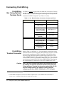
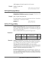
The tree relays and analog bus relays have the same channel number no
matter what operating mode the Multiplexer is. But the channel relays
(CH000-255) may have different channel numbers under different operating
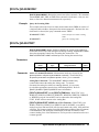
mode. See the following table:
Operating Mode
Valid Channel
Number
Corresponds to 1-Wire Mode Channel
1-wire
000-255
000-255
2-wire
000-127
000-031, 064-095, 128-159, 192-223
(Channel 000 is paired with channel 032, 001
is paired with 033, etc. Channel 064 is paired
with 096, 065 with 097, etc. Channel 128 is
paired with 160, channel 129 with 161, etc.
Channel 192 is paired with 224, channel 193
with 225, etc.)
3-wire
000-063
000-031, 128-159
4-wire
000-063
000-031, 128-159
Configuring the Agilent E8462A Multiplexer
29
Refer to Chapter 3 of this Manual, the command [ROUTe:]CLOSe for the
paired channel information.
You must specify the operating mode BEFORE you execute the commands
OPEN, CLOSe, and SCAN. Pay attention to the valid channel numbers
when you open, close or scan the specific channel(s) in different operating
modes.
The channels can be addressed using channel numbers or channel ranges.
You can address the following:
• single channels (@ccbnnn);
• multiple channels (@ccbnnn,ccbnnn,...);
• sequential channels (@ccbnnn:ccbnnn);
• groups of sequential channels (@ccbnnn:ccbnnn,ccbnnn:ccbnnn);
• or any combination of the above.
Card Numbers
The card number (ss of the channel list) identifies the module within a
multiple switching cards. The card number assigned depends on the switch
configuration used. Leading zeroes can be ignored for the module (card)
number.
Single-module. In a single Multiplexer module configuration, the card
number is always 01 or 1.
Multiple-module. In a multiple-module configuration, modules are set to
successive logical addresses. The module with the lowest logical address is
always card number 01. The module with the next successive logical address
is card number 02, and so on.
Figure 1-13 illustrates the card numbers and logical addresses of a typical
multiple-module configuration.
Command
Module
CARD NUMBER 01
Multiplexer Number 1
Logical Address = 112
Secondary Address = 14
CARD NUMBER 02
Multiplexer Number 2
Logical Address = 113
CARD NUMBER 03
Multiplexer Number 3
Logical Address = 114
Figure 1-13. Card Numbers in a Multiple-module Configuration
30
Configuring the Agilent E8462A Multiplexer
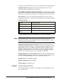
Channel Numbers,
Ranges, and Lists
Note
The Agilent E8462A Multiplexer channel numbers are 0000 through 0255
under the 1-wire mode. The channels can be addressed using individual
channel numbers or channel ranges.
For all other modes, the “channel” is actually used to refer to the paired
channel. Under 2-wire mode, there are 128 2-wire paired channels, under
3-wire and 4-wire modes, there are only 64 paired 3-wire or 4-wire
channels. See Chapters 2 and 3 for more information of paired channels.
Use commas (,) to form a channel list or use a colon (:) to form a channel
range. Only valid channels can be accessed in a channel list or channel
range. Also, the channel list or channel range must be from a lower channel
number to a higher channel number. For example, CLOS(@1000:1015) is
acceptable, but CLOS(@1015:1000) generates an error.
Using the channel range (@cc0000:cc9999) with the SCAN command
causes all channels to be scanned except the tree relays (CH9000-9204).
Tree relays switch the channels to the appropriate terminal lines and
therefore are not included in a scan list.
Below are some SCPI commands and a description of their effect on channel
lists and ranges.
Channel Lists:
FUNC 1, WIRE2
CLOS(@1000,1001)
OPEN(@1003,1010)
Set the module to 2-wire mode.
Close paired channels 000 and
001 on card #1 (channels 0, 1,
32 & 33 will be closed together).
Open paired channels 03 and 10
on card #1.
Channel Ranges:
FUNC 1, WIRE1
OPEN (@1000:1255)
CLOS (@1000,1127)
SCAN (@1128:1255)
Set the module to 1-wire mode.
Open all channels on card #1.
Close channels 000 and 127 on
card #1.
Define channels 128-255 to be
scanned.
Configuring the Agilent E8462A Multiplexer
31
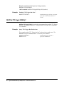
Initial Operation
You must download the Agilent E8462A SCPI driver into the Agilent
E1405/E1406 Command Module to perform the initial operation.
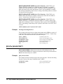
At power-on or following a reset of the module (*RST command), all 256
channels are open. A *RST command invalidates the current scan list (that
is, you must specify a new scan list). Command parameters are set to the
default conditions as shown below.
Parameter
Default
Value
Description
ARM:COUNt
1
Number of scanning cycles is one.
TRIGger:SOURce
IMM
Advances through a scanning list
automatically.
INITiate:CONTinuous
OFF
Continuous scanning disabled.
OUTPut[:STATe]
OFF
Trigger output from EXT, TTL, or ECL
sources is disabled.
[ROUTe:]FUNC
WIRE2
Operating mode is set to WIRE2 at poweron. This mode is NOT changed by *RST.
[ROUTe:]SCAN:MODE
NONE
Channel list is not set up.
[ROUTe:]SCAN:PORT
NONE
Analog bus connections are disabled from
channels.
Execute SCAN:PORT ABUS to enable use of the analog bus for the SCAN
command. The SCPI driver will then automatically open and close the five
analog bus relays during a scan. A CLOSe command on a channel will also
automatically close the appropriate tree relays for the given
ROUTe:FUNCtion (see Page 13 "Figure 1-1. Agilent E8462A Simplified
Schematic" ).
Note
Do not execute register writes if you are controlling the module by a high
level driver such as SCPI or VXIplug&play. Changing values in registers
with register writes will confuse the driver because it has a record of the
register states after the last command executed by the driver. The driver
record of register states is not updated by a register write, only the register
value is changed. Therefore, the driver will not know the module state.
However, the SCPI driver will re-sync to the hardware if a CLOSe? query
is executed.
The following example program was developed with the ANSI C language
using the Agilent VISA extensions. The program was written and tested in
Microsoft® Visual C++ but should compile under any standard ANSI C
compiler.
To run the program you must have the Agilent SICL Library, the Agilent
VISA extensions, and an Agilent 82340 or 82341 GPIB module installed
and properly configured in your PC. An Agilent E1406 Command Module
is required.
32
Configuring the Agilent E8462A Multiplexer
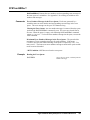
Example: Reset,
Self Test, Module
ID, and Close
Channel
The following example reads the module ID string, performs module
self-test, displays the results, closes channel 0002 and queries the channel
closure state. The result is returned to the computer and displayed
(“1” = channel closed, “0” = channel open).
#include <visa.h>
#include <stdio.h>
#include <stdlib.h>
/* Module Logical address is 112, secondary address is 14*/
#define INSTR_ADDR “GPIB0::9::14::INSTR”
int main()
{
ViStatus errStatus;
ViSession viRM;
ViSession E8462A;
char id_string[256];
char selftst_string[256];
char ch_state;
/*Status from each VISA call*/
/*Resource mgr. session */
/* Module session */
/*ID string*/
/*self-test string*/
/*channel open/close state*/
/* Open the default resource manager */
errStatus = viOpenDefaultRM ( &viRM);
if(VI_SUCCESS > errStatus){
printf(“ERROR: viOpenDefaultRM() returned 0x%x\n”,errStatus);
return errStatus;}
/* Open the Module instrument session */
errStatus = viOpen(viRM,INSTR_ADDR, VI_NULL,VI_NULL,&E8462A);
if(VI_SUCCESS > errStatus){
printf(“ERROR: viOpen() returned 0x%x\n”,errStatus);
return errStatus;}
/* Reset the Module */
errStatus = viPrintf(E8462A, “*RST;*CLS\n”);
if(VI_SUCCESS > errStatus){
printf(“ERROR: viPrintf() returned 0x%x\n”,errStatus);
return errStatus;}
/* Query the Module ID string */
errStatus = viQueryf(E8462A,”*IDN?\n”,”%t”,id_string);
if (VI_SUCCESS > errStatus) {
printf(“ERROR: viQueryf() returned 0x%x\n”,errStatus);
return errStatus;}
printf(“ID is %s\n”,id_string);
/* Close Channel 002 */
errStatus = viPrintf(E8462A, “FUNC 1,WIRE1;CLOS (@1002)\n”);
if(VI_SUCCESS > errStatus){
printf(“ERROR: viPrintf() returned 0x%x\n”,errStatus);
return errStatus;}
Configuring the Agilent E8462A Multiplexer
33
/* Query State of Channel 002 */
errStatus=viQueryf(E8462A,”ROUT:CLOS? (@10002)\n”,”%t”,ch_state);
if (VI_SUCCESS > errStatus) {
printf(“ERROR: viQueryf() returned 0x%x\n”,errStatus);
return errStatus;}
printf(“Channel State is: %s\n”,ch_state);
/* Open Channel 002 */
errStatus = viPrintf(E8462A, “OPEN (@10002)\n”);
if(VI_SUCCESS > errStatus){
printf(“ERROR: viPrintf() returned 0x%x\n”,errStatus);
return errStatus;}
/* Close the Module Instrument Session */
errStatus = viClose (E8462A);
if (VI_SUCCESS > errStatus) {
printf(“ERROR: viClose() returned 0x%x\n”,errStatus);
return 0;}
/* Close the Resource Manager Session */
errStatus = viClose (viRM);
if (VI_SUCCESS > errStatus) {
printf(“ERROR: viClose() returned 0x%x\n”,errStatus);
return 0;}
return VI_SUCCESS;
}
34
Configuring the Agilent E8462A Multiplexer
Chapter 2
Using the Multiplexer
What’s in This Chapter
This chapter contains the following sections:
• Reset Conditions . . . . . . . . . . . . . . . . . . . . . . . . . . . . . . . . . .
• Switching or Scanning . . . . . . . . . . . . . . . . . . . . . . . . . . . . .
• Switching Channels to the Analog Bus. . . . . . . . . . . . . . . . .
• Recalling and Saving States . . . . . . . . . . . . . . . . . . . . . . . . .
• Detecting Error Conditions . . . . . . . . . . . . . . . . . . . . . . . . . .
Reset Conditions
Page 35
Page 36
Page 36
Page 52
Page 53
At power-on or following the reset of the module (*RST command), all 256
channel relays, 21 tree relays, and five analog bus connection relays are
open. The nine C relays are in their normally closed position. In addition,
after a *RST command, the scan channel list is empty. Table 2-1 lists the
parameters and default values for the functions following turn-on or reset.
Table 2-1. Agilent E8462A Default Conditions for Power-on and Reset
Parameter
ARM:COUNt
Default
Value
1
Description
Number of scanning cycles is one.
TRIGger:SOURce
IMM
Advances through a scanning list automatically.
INITiate:CONTinuous
OFF
Continuous scanning disabled.
OUTPut[:STATe]
OFF
Trigger output from EXT, TTL, or ECL sources is disabled.
[ROUTe:]SCAN:MODE
NONE
Channel list is not set up.
[ROUTe:]SCAN:PORT
NONE
Analog bus connections are disabled.
[ROUTe:]FUNCtion
WIRE2
2-wire mode is set at power-on. FUNCtion is not changed by *RST.
DIAGnostic:INTerrupt[:LINE]
1
DIAGnostic:INTerrupt:TIME
0.005
DIAGnostic:SCAN:DELay
0.0
Interrupt line setting. NOT changed by *RST.
Sets interrupt timer value. NOT changed by *RST.
Wait time between opening and closing channels. Reset by *RST.
Channel state
All 256 channels are open (CH000-255 are open).
Tree relays state
All 22 tree relays are open (CH9000-9021).
Routing relays state
All routing relays are open and use the normally closed path (CH9100-9108).
Analog bus connection relay status
5 analog bus relays are open (CH9200-9204).
Channel list from SCAN command (after *RST)
Channel list is empty following a reset of the module with *RST command.
Using the Multiplexer
35
Switching or Scanning
There are two general ways to use the E8462A Relay Multiplexer. First, you
can use the ROUTe:FUNCTion command subsystem (see Chapter 3) to set
up the multiplexer in any of its 12 operating modes: 1-Wire (1-1X256,
2-1X128, 4-1X64, 8-1X32), 2-Wire (1-2X128, 2-2X64, 4-2X32, 8-2X16),
3-Wire (1-3X64), or 4-Wire (1-4X64, 2-4X32, 4-4X16). You can then use
the [ROUTe:]CLOSe or [ROUTe:]OPEN commands to control individual
channel relays. In the 2-Wire, 3-Wire, and 4-Wire modes, banks of channels
are paired together such that when you close one channel the paired relay(s)
also close automatically. The ROUTe command subsystem automatically
closes the appropriate tree relays depending on the multiplexer mode.
Alternately, you can set the multiplexer mode and scan through a list of
channels. Scanning involves sequentially closing/opening channels in a
channel list. Use the ROUTe:SCAN command to set the scan mode, use the
analog bus, and specify the channel in the channel list.
The channel list used in the ROUTe command subsystem includes the 256
channel relays (CH000-255). Valid channel numbers depend on the
specified mode. The 22 tree relays (CH9000-9021), the nine routing relays
(CH9100-9108) and five analog bus connection control relays (CH92009204) are automatically set depending on the specified mode.
Note
You must specify the Multiplexer’s operating mode with the
[ROUTe:]FUNCtion command before executing the [ROUTe:]CLOSe,
OPEN, or SCAN functions. This closes the appropriate tree relays
configuring the module for the specified mode. See the ROUTe command
in Chapter 3 for more details. Also, Figure 1-6 on page 20, Figure 1-7 on
page 21, and Figure 1-8 on page 22 show the valid channel and front panel
connections for 1-, 2-, 3- and 4-wire modes.
Note
Pay special attention to the valid channel numbers when you execute these
SCPI commands. Refer to the comments of the ROUTe subsystem
commands in Chapter 3 for more information of the paired channel and
valid channel numbers.
Switching Channels
to the Analog Bus
When the multiplexer FUNCtion is set to one of the WIREn modes (any
mode but NONE), the appropriate tree relays are automatically closed at the
close channel command connecting the channel to the appropriate terminal
bus line (Ter0-Ter15). To use the analog bus, however, you must execute the
ROUTe:SCAN:PORT command. The analog bus relays will automatically
close and open when a scanning operation is executed and the mode is not
NONE. Only the tree relays needed for the closed channel are closed. All
others are opened. All tree relay and channel realys are opened when power
is removed from the module, the module is reset with the *RST command
or ROUTe:FUNCtion NONE is executed reconfiguring the module. These
actions also open all other relays that are closed. You must manually close
the tree relays, routing relays and analog bus relays when you specify the
FUNCtion to be NONE.
36
Using the Multiplexer
Performing
Measurements via
Analog Bus
To perform measurements via analog bus, you need to either manually close
the analog bus connection control relays (CH9200-9204) through command
ROUTe:CLOSe or execute the command ROUTe:SCAN:PORT ABUS.
1-wire, 2-wire, 3-wire and 4-wire measurements can be made via analog bus
by connecting CH9200-9204.
1-Wire Mode:
All the 256 channel relays are connected to Ter0 and connected to analog
bus H1 through closing AB200 (CH9200). Routing relay C108 will be
automatically switched between banks as required to route all banks to H1.
Valid channel numbers are 000 through 255. Analog Bus L1 will be
connected to Analog Bus G and to the user’s common ground on Terminal 3.
2-Wire Mode:
The 256 channel relays form 128 2-wire pairs which are connected to Ter0
and Ter1 Terminal buses. Through closing AB200 and AB201
(CH9200-9201), the specific channel pair is connected to analog bus H1 and
L1 to perform 2-wire measurements such as voltage and 2-wire resistance
measurements. Analog Bus H2 and L2 may also be connected through
channels 9203-9204 and tree relays 9109 and 9102 to provide a current
source for the resistance measurements. Also, Analog Bus L1 also be
connected to G for voltage measurements. Valid channel numbers are 000
through 127. From the perspective of the 1-Wire mode, channel 000
becomes channel 000 HI, channel 032 becomes channel 000 LO, etc. Refer
to Figure 1-7 on page 21.
3-Wire Mode:
The 256 channel relays form 64 3-wire pairs which connect to H1, L1 and
L2 through closing AB200, AB201, and AB204 (CH9200, 9201 and 9204)
respectively. The 64 3-wire pairs are: Banks 0/2, 1/3, 4/6 and 5/7. Valid
channel numbers are 000 through 063. From the perspective of the 1-wire
mode, channel 000 becomes channel 000 HI, channel 032 becomes channel
000 LO1, and channel 064 becomes channel 000 LO2.
4-Wire Mode:
The 256 channel relays form 64 4-wire pairs which connect to H1, L1, H2,
and L2 by closing AB200, AB201, AB203, and AB204 (CH9000, 9201,
9203 and 9204) . In this mode the 4-wire pairs are: Banks 0/2, 1/3, 4/6 and
5/7. Valid channel numbers are 000 through 063. From the perspective of the
1-wire mode, channel 000 becomes channel 000 HI1, channel 032 becomes
channel 000 LO1, channel 064 becomes channel 000 LO2, and channel 096
becomes channel 000 HI2.
The analog bus connection control relays are closed to connect specific
4-wire pairs to analog bus H1, L1, H2, and L2. In this mode the 4-wire pairs
are: Banks 0/2, 1/3, 4/6 and 5/7. The valid channel numbers that can be
closed/opened/scanned are 000 through 63. Refer to Chapter 3, ROUTe
command subsystem for more information on valid channel numbers and
paired channels under different operating modes.
Using the Multiplexer
37
Mode: WIRE1
Description:
one 1-wire x 256 ch MUX
Figure 2-1 shows the 1-Wire mode (configured as a 1 x 256 multiplexer).
• Tree Relays: T0 through T7 are closed to connect the specific channels
to Terminal Bus Ter0 and Ter1.
• Routing Relays: C100 and C108, toggles between the Ter0 and Ter1
Front Panel Pin-out:
See Figure 1-6
terminal bus line to route all channels to Ter0 (1-wire).
• Valid Channel List: All 256 channels (000-255).
• Analog Bus: All the channels can be also connected to analog bus line
H1 by closing AB200 (CH9200) and toggling C108 (CH9108).
• SCPI Example: How to set the mode and close a channel.
FUNC 1, WIRE1
CLOS (@10005)
Specify the 1-Wire mode.
Close channel 5.
1-Wire @ Ter0
Figure 2-1. 1-Wire (1 x 256 Multiplexer) Operating Mode
38
Using the Multiplexer
Mode: WIRE2
Description:
one 2-wire x 128 ch MUX
Figure 2-2 shows the 2-Wire mode. All 256 channels form 128 2-wire pairs
which connect to Terminal Bus Ter0 and Ter1.
• Tree Relays: T0 through T7 are closed to connect the specific channel
pairs to Terminal Bus Ter0 and Ter1.
Front Panel Pin-out:
See Figure 1-7
• Routing Relays: C100 and C108 remain connected to Ter0.
• Valid Channel List: 000-127.
• Analog Bus: All the channels can be also connected to analog bus lines
H1 and L1 by closing AB200 (CH9200) and AB201 (CH9201).
• SCPI Example: How to make a 2-wire measurement with a paired
channel (CH000 and CH032).
FUNC 1, WIRE2
CLOS (@10000)
Specify 2-wire Mode.
Close paired Ch000 and Ch032
2-Wire @ Ter0 and
Ter1
Figure 2-2. 2-Wire Operating Mode
Using the Multiplexer
39
Mode: WIRE3 and
WIRE4
Description:
one 3-wire x 64 ch MUX
or
one 4-wire x 64 ch MUX
Front Panel Pin-out:
See Figure 1-8
The same basic configuration is used for both the 3-Wire and the 4-Wire
modes. Refer to Figure 2-3. In the 3-Wire mode, relays 0-31 and 128-159
switch to terminal bus Ter0, relays 32-63 and 160-191 switch to Ter1, and
relays 64-95 and 192-223 switch to Ter5. In the 4-Wire mode, relays 0-31
and 128-159 switch to terminal bus Ter0, relays 32-63 and 160-191 switch
to Ter1, relays 64-95 and 192-223 switch to Ter5 and relays 96-127 and
224-255 switch to Ter4.
In either mode the 256 channels will form 64 wire pairs. The valid channel
numbers are 0 through 63. Measurements can be done either through the
four terminal bus Terminals 0, 1, 5, and 4 or through the analog bus by
closing the analog bus relays AB200, AB201, AB203 and AB204 (CH9200,
9201, 9203, 9204).
For 4-Wire measurements, you would typically use a pair of channels from
banks 0 and 2 for the voltage sense and another pair of channels from banks
4 and 6 for the current source, these four channels forms one 4-wire pair.
Closing any channel in the pair automatically closes the other channel in the
pair. The following SCPI example shows how to set the 4-Wire mode and
how to close the paired channels.
FUNC 1, WIRE4
CLOS (@100)
Configure 4-wire mode.
Close channel 00. Channels 32,
64, 96 are 4-wire pair and will
close automatically.
Other Modes
The Agilent E8462A can also be configured as two 128x1, four 64x1, eight
32x1, two 64x2, four 32x2, eight 16x2, two 32x4 or four 16x4 multiplexers.
The ROUTe:FUNCtion command can be used to automatically set these
modes. You must use mode NONE and manually set all tree and routing
relays if you want a mixture of modes (e.g., one 128x1, one 32x2 and one
16x4).
40
Using the Multiplexer
NOTE: See Figure 1-8 for 3-wire and 4-wire front panel pin-out.
3-Wire uses Ter0,
Ter1 and Ter4
4-Wire uses Ter0,
Ter1, Ter4 and Ter5
Figure 2-3. 3-Wire and 4-wire Operating Mode
Using the Multiplexer
41
Mode: WIRE1x2 and
WIRE2x2
Description:
two 1-wire x 128 ch MUX
or
two 2-wire x 64 ch MUX
The Agilent E8462A can be configured as two 128 x 1 or two 64 x 2
multiplexers. Figure 2-4 illustrates these configurations.
Front Panel Pin-out: See Figure 1-6 for 1-wire or Figure 1-7 for 2-wire.
Figure 2-4. Two 1 x 128 or Two 2 x 64 Multiplexer
42
Using the Multiplexer
Mode: WIRE1x4,
WIRE2x4,
WIRE4x2
Description:
four 1-wire x 64 ch MUX
or
four 2-wire x 32 ch MUX
or
two 4-wire x 32 ch MUX
The Agilent E8462A can be configured as four 64 x 1, four 32 x 2 and two
32 x 4 multiplexers. In this configuration, the 256 channels are divided into
8 groups, each one is a 32 x 1 multiplexer. The 8 groups are connected to
eight terminal bus (Terminals 0, 2, 4, 6, 8, 10, 12, 14) by closing 16 related
tree relays. These modes are automatically set with the ROUTe:FUNC
command which automatically sets the appropriate tree relays.
Front Panel Pin-out: See Figure 1-6 for 1-wire or Figure 1-7 for 2-wire or
Figure 1-8 for 4-wire.
Figure 2-5. Four 1 x 64, Four 2 x 32 or Two 4 x 32 Multiplexer
Using the Multiplexer
43
Mode: WIRE1x8,
WIRE2x8,
WIRE4x4
Description:
eight 1-wire x 32 ch MUX
or
eight 2-wire x 16 ch MUX
or
four 4-wire x 16 ch MUX
The Agilent E8462A can be configured as eight 32 x 1, eight 16 x 2 and four
16 x 4 multiplexers. In this configuration, the 256 channels are divided into
8 groups, each one is a 32 x 1 multiplexer. The 8 groups are connected to
eight terminal bus (Terminals 0, 2, 4, 6, 8, 10, 12, 14) by closing 16 related
tree relays. These modes are automatically set with the ROUTe:FUNC
command which automatically sets the appropriate tree relays.
Front Panel Pin-out: See Figure 1-6 for 1-wire or Figure 1-7 for 2-wire or
Figure 1-8 for 4-wire.
Figure 2-6. Eight 1 x 32, Eight 2 x 16 or Four 4 x 16 Multiplexer
44
Using the Multiplexer
Scanning Channels
Scanning the Multiplexer channels consists of sequentially closing a channel
(and its associated tree relays), making some measurement , opening that
channel, and then repeating that process with the next channel in a channel
list. You can make a single scan through the channel list or scan a multiple
number of times. You can also scan the channel list continuously until the
scan is aborted.
The TRIGger:SOURce command specifies the source to advance the scan.
The OUTPut command can be used to enable the E1406A Command
Module's “Trig Out” port, TTL Trigger bus line (0-7) or ECL Trigger bus
lines (0-1). Figure 2-7 illustrates the commands in the scanning sequence.
ARM:COUN <number>
TRIG:SOUR BUS|HOLD|EXT|
IMM|TTLT|ECLT
OUTP[:EXT] 1|0|ON|OFF
OUTP:ECLT 1|0|ON|OFF
OUTP:TTLT 1|0|ON|OFF
INIT:CONT 1|0|ON|OFF
SCAN:MODE
NONE|VOLT|RES|FRES
SCAN:PORT ABUS
SCAN <channel_list>
INIT
TRIG
Figure 2-7. Command Sequence for Scanning Channels
Using the Multiplexer
45
You can scan a channel or a list of channels using the SCAN command. The
analog bus connection control relays (CH9200-9204) are automatically
closed when you specify the command SCAN:PORT ABUS. This command
is required for the analog bus control relays to function during the scan
through the channel list. The default value is SCAN:PORT NONE which
does not automatically close these relays and connect channels to the analog
bus. They may however, still be manually controlled with the OPEN and
CLOSe commands.
At power-on or after resetting the module with the *RST command,
connection to the analog bus is disabled for scan operations. You must
execute the command SCAN:PORT ABUS to enable analog bus connection
control relay operation. Access is through the front panel analog bus
connector (usually connected to other multiplexers or to the E1411B
multimeter) or through the terminal module (Opt 014) “VM Input” and “I”
terminals on P109 connector (see Figure 1-1 on page 13).
Synchronizing the
Multiplexer with a
Multimeter
Measurement Set-Up
This example uses the TTL VXIbus triggers (TTLT 0-7) to synchronize
channel closures with the Agilent E1412A 6 1/2-Digit Multimeter. DC
Voltage measurements are performed. Measurement synchronization is
attained by the multimeter sending a voltmeter complete signal on TTL
Trigger Line 1 and receiving the channel closed signal on TTL Trigger Line
0. Similarly, the multiplexer module sends its channel closed signal on TTL
0 and receives its channel advance signal on TTL 1. Note; Figure 2-8 shows
connections between the Agilent E1406A Command Module Trigger In and
Trigger Out to the Agilent E1412A Trigger In and Voltmeter Complete. This
simply demonstrates an alternate method of synchronizing the
measurements.
• Agilent E1412A has an GPIB select code = 7, primary address = 09
and secondary address = 03.
• Agilent E8462A has an GPIB select code = 7, primary address = 09
and secondary address = 14.
• Controller is an IBM compatible PC, the programming language is
Visual C/C++ with Agilent VISA extensions.
46
Using the Multiplexer
Figure 2-8. Scanning with VXIbus Triggers
The following example program was developed with the ANSI C language
using the Agilent VISA extensions. The program was written and tested in
Microsoft® Visual C++ but should compile under any standard ANSI C
compiler.
To run the program you must have the Agilent SICL Library, the Agilent
VISA extensions, and an Agilent 82340 or 82341 GPIB module installed
and properly configured in your PC. An Agilent E1406 Command Module
is required.
This following example resets and configures the multimeter for DC
Voltage measurements, resets and configures the multiplexer for 2-Wire
configuration TTL Trigger bus synchronization, use of the analog bus, and
scanning channels 00 through 09.
#include <visa.h>
#include <stdio.h>
#include <stdlib.h>
/* Interface address is 112, Module secondary address is 14*/
#define INSTR_ADDR “GPIB0::9::14::INSTR”
/* interface address for Agilent E1412 Multimeter */
#define MULTI_ADDR “GPIB0::9::3::INSTR”
int main()
Using the Multiplexer
47
{
ViStatus errStatus;
/*Status from each VISA call*/
ViSession viRM;
/*Resource mgr. session */
ViSession E8462A;
/* Module session */
ViSession E1412A;
/* Multimeter session */
viSetAttribute (E1412A,VI_ATTR_TMO_VALUE,268435456)
/* multimeter timeout value */
int ii;
char opc_int[21]
double readings [10];
/* loop counter */
/* OPC? variable */
/* Reading Storage*/
/* Open the default resource manager */
errStatus = viOpenDefaultRM ( &viRM);
if(VI_SUCCESS > errStatus)
printf(“ERROR: viOpenDefaultRM() returned 0x%x\n”,errStatus);
/* Open the Module instrument session */
errStatus = viOpen(viRM,INSTR_ADDR, VI_NULL,VI_NULL,&E8462A);
if(VI_SUCCESS > errStatus)
printf(“ERROR: viOpen() returned 0x%x\n”,errStatus);
/* Open the Multimeter instrument session */
errStatus = viOpen(viRM,MULTI_ADDR, VI_NULL,VI_NULL,&E1412A);
if(VI_SUCCESS > errStatus)
printf(“ERROR: viOpen() returned 0x%x\n”,errStatus);
/* Reset the Multimeter, clear status system */
errStatus = viPrintf(E1412A, “*RST;*CLS\n”);
if(VI_SUCCESS > errStatus)
printf(“ERROR: viPrintf() returned 0x%x\n”,errStatus);
/*Configure Multimeter for DCV measurements, 12 V max, min resolution */
errStatus = viPrintf(E1412A, “CONF:VOLT 12,MIN\n”);
if(VI_SUCCESS > errStatus)
printf(“ERROR: viPrintf() returned 0x%x\n”,errStatus);
/* Set multimeter trig input TTLT0 Trigger Line */
errStatus = viPrintf(E1412A, “TRIG:SOUR:TTLT0\n”);
if(VI_SUCCESS > errStatus)
printf(“ERROR: viPrintf() returned 0x%x\n”,errStatus);
/* Enable Measurement Complete on TTL2 */
errStatus = viPrintf(E1412A, “OUTP:TTLT1 ON\n”);
if(VI_SUCCESS > errStatus)
printf(“ERROR: viPrintf() returned 0x%x\n”,errStatus);
/* Enable Trigger Delay */
errStatus = viPrintf(E1412A, “TRIG:DEL 0.001\n”);
if(VI_SUCCESS > errStatus)
printf(“ERROR: viPrintf() returned 0x%x\n”,errStatus);
48
Using the Multiplexer
/* Set Multimeter for 10 triggers */
errStatus = viPrintf(E1412A, “TRIG:COUN 10\n”);
if(VI_SUCCESS > errStatus)
printf(“ERROR: viPrintf() returned 0x%x\n”,errStatus);
/* Pause until multimeter is ready */
errStatus = viQueryf(E1412A, “*OPC?\n”,”%t”,opc_int);
if(VI_SUCCESS > errStatus)
printf(“ERROR: viQueryf() returned 0x%x\n”,errStatus);
/* Initialize Multimeter, wait for trigger */
errStatus = viPrintf(E1412A, “INIT\n”);
if(VI_SUCCESS > errStatus)
printf(“ERROR: viPrintf() returned 0x%x\n”,errStatus);
/* Reset E8462A */
errStatus = viPrintf(E8462A,”*RST;*CLS\n”);
if (VI_SUCCESS > errStatus)
printf(“ERROR: viPrintf() returned 0x%x\n”,errStatus);
/* Enable Trigger Output on TTL2 */
errStatus = viPrintf(E8462A, “OUTP:TTLT0 ON\n”);
if(VI_SUCCESS > errStatus)
printf(“ERROR: viPrintf() returned 0x%x\n”,errStatus);
/* Set Trigger Input On TTL 1 */
errStatus = viPrintf(E8462A, “TRIG:SOUR TTLT1\n”);
if(VI_SUCCESS > errStatus)
printf(“ERROR: viPrintf() returned 0x%x\n”,errStatus);
/* Set Multiplexer to 2-Wire mode */
errStatus = viPrintf(E8462A, “ROUT:FUNC ,WIRE2\n”);
if(VI_SUCCESS > errStatus)
printf(“ERROR: viPrintf() returned 0x%x\n”,errStatus);
/* Set Multiplexer to Voltage mode */
errStatus = viPrintf(E8462A, “SCAN:MODE VOLT\n”);
if(VI_SUCCESS > errStatus){
printf(“ERROR: viPrintf() returned 0x%x\n”,errStatus);}
/* Enable Analog Bus */
errStatus = viPrintf(E8462A, “SCAN:PORT ABUS\n”);
if(VI_SUCCESS > errStatus){
printf(“ERROR: viPrintf() returned 0x%x\n”,errStatus);}
/* Set Scan List */
errStatus = viPrintf(E8462A, “SCAN(@100:109)\n”);
if(VI_SUCCESS > errStatus){
printf(“ERROR: viPrintf() returned 0x%x\n”,errStatus);}
Using the Multiplexer
49
/* Pause until ready */
errStatus = viQueryf(E8462A, “*OPC?\n”,”%t”,opc_int);
if(VI_SUCCESS > errStatus){
printf(“ERROR: viQueryf() returned 0x%x\n”,errStatus);}
/* Start Scan */
errStatus = viPrintf(E8462A, “INIT\n”);
if(VI_SUCCESS > errStatus){
printf(“ERROR: viPrintf() returned 0x%x\n”,errStatus);}
/* Get readings from Multimeter */
errStatus = viQueryf(E1412A, “FETC?\n”,”%,10lf”,readings);
if(VI_SUCCESS > errStatus){
printf(“ERROR: viQueryf() returned 0x%x\n”,errStatus);}
for (ii=0;ii<10;ii++) {
printf (Reading %d is: %lf\n”,ii,readings[ii]); }
/* Reset E8462A to open all channels*/
errStatus = viPrintf(E8462A,”*RST\n”);
if (VI_SUCCESS > errStatus) {
printf(“ERROR: viPrintf() returned 0x%x\n”,errStatus);}
/* Close the E8462A Instrument Session */
errStatus = viClose (E8462A);
if (VI_SUCCESS > errStatus)
printf(“ERROR: viClose() returned 0x%x\n”,errStatus);
/* Close the Multimeter Instrument Session */
errStatus = viClose (E1412A);
if (VI_SUCCESS > errStatus)
printf(“ERROR: viClose() returned 0x%x\n”,errStatus);
/* Close the Resource Manager Session */
errStatus = viClose (viRM);
if (VI_SUCCESS > errStatus)
printf(“ERROR: viClose() returned 0x%x\n”,errStatus);
return VI_SUCCESS;
}
50
Using the Multiplexer
Using BUS Triggers
with an External Device
to Scan Channels
Refer to Figure 2-9. This example uses the BUS trigger (GET or *TRG) to
synchronize channel closures with the Agilent 3457A Multimeter. A DC
voltage measurement is performed. Measurement synchronization is
attained by:
1. After the multimeter and multiplexer are configured, iniitate the scan
on the Agilent E8462A (INIT command). This closes the first channel.
2. FETCH? the reading from the multimeter.
3. Trigger the multiplexer (*TRG command). This opens the channel
and closes the next channel in the list. After the relay settles, the
Agilent E1406A outputs a trigger to trigger the multimeter.
4. Repeat steps 2 and 3 in a loop until all channels in the channel list
have been scanned.
Figure 2-9. Scanning with an External Device
The actual C++ language program is similar to the previous example and
will not be presented again.
Hybrid MUX
Configuration
The module can be configured into segments of channels that are of different
modes using the FUNCtion NONE and manually setting appropriate tree
switches. Figures 1-1 and 2-1 through 2-6 show the location of tree relays
and will help you determine what relays you should close. An example
program on the driver CD (in the examples subdirectory) titled hybrid.c
configures part of the module as 1-wire, part as 2-wire and part as 4-wire.
Distribution MUX
You can use the multiplexer to distribute a signal to many different channels
as well as multiplexing many channels into one signal line. The example
program distrib.c on the drivers CD (in the examples subdirectory) shows
how a signal input on terminal line TER0 can be distributed to 128 different
channels.
Using the Multiplexer
51
Recalling and Saving States
This section contains information about saving and recalling a Multiplexer
module state.
Saving States
The *SAV <numeric_state> command saves the current instrument state.
The state number (0-9) is specified in the state parameter. The following
settings are saved:
• Channel Relay State (CH000-256 open or closed);
• Tree Relay State (CH9000-9021 open or closed);
• Routing Relay Stare (CH9100-9108 open or closed).
• Analog Bus Connection Control Relay State (CH9200-9204 open or
closed)
• ARM:COUNt Value
• TRIGger:SOURce Mode
• OUTPut[:STATe] Configuration
• INITiate:CONTinuous Mode
• [ROUTe:]FUNCtion Mode
• [ROUTe:]SCAN:MODE Mode
• [ROUTe:]SCAN:PORT Mode
• DIAGnostic:SCAN:DELay Time
• DIAGnostic:INTerrupt[:LINE] Setting
• DIAGnostic:INTerrupt:TIME Time
52
Recalling States
The *RCL <numeric_state> command recalls a previously saved state.
Enter the number (0-9) in the state parameter of the desired saved state. If
*SAV was not previously executed using the selected number, the
Multiplexer will be configured to the reset values (see "Table 2-1. Agilent
E8462A Default Conditions for Power-on and Reset" on page 35).
Note
Scan lists are not saved when a state is saved. You must re-enter your scan
list after recalling a state.
Using the Multiplexer
Detecting Error Conditions
There are two general approaches to error checking. The simplest, but most
time consuming, is to ask the instrument whether there are errors at every
step of the switching process. This is called “polling” and is illustrated in the
two previous program examples.
Using Interrupts
With Error
Checking
Analog Bus
2-Wire Resistance
Measurements
The second approach involves the use of interrupts. In this approach, the
program monitors the Multiplexer's Standard Event Status Register for an
error condition. If no errors occur, the Multiplexer functions as
programmed. If errors do occur, the Multiplexer interrupts the computer,
and the error codes and messages are read from the error queue.
[ROUTe:]SCAN:MODE RES sets the scanning mode to 2-wire resistance
measurements. The current source from the ohmmeter to the unknown
resistance is supplied over analog bus lines H2 and L2. The RES mode
closes Tree relays T9 and T2 which connect H2 to H1 and L2 to L1. This
configuration allows H2 and L2 to source the current through the unknown
resistance and H1 and L1 to sense the voltage and make the resistance
measurement. You must make this connection manually if you use the
FUNCtion mode NONE or register program the multiplexer and desire
2-wire ohms measurements.
Using the Multiplexer
53
Routing Relay
Operation
The Agilent E8462A uses eight Form C (C100 - C107) relays to route closed
channels to the appropriate terminal line (Ter0 to Ter15) dependent on the
FUNCtion mode set. A ninth Form C relay (C108) is used to switch terminal
lines to the analog bus. Figure 2-10 shows routing relays C100, C101 and
C102. These are three of the nine form C routing relays.
WIRE1 (1-wire) Example
In the 1-wire mode, all channels are routed to terminal line Ter0. Tree relays
T0 through T7 are closed to connect channels to either terminal line Ter0 or
Ter1. Tree relay T0 connects channels 0 - 15 to Ter0 and channels 32 - 47
to Ter1. Tree relay T1 connects channels 16 - 31 to Ter0 and channels 48 63 to Ter1. Tree relays T2 through T7 make similar connections to Ter0 and
Ter1. The routing relay C100 toggles between terminal lines Ter0 and Ter1
depending on the channel that is closed to route all channels to Ter0. When
you specify [ROUTe:]FUNCtion NONE, you are required to switch the
routing relays as required.
Figure 2-10. Routing Relay Example (3 of 9 Form C Relays).
Function Mode Topologies
The following pages describe the topologies of the 12 modes you set with
the [ROUTe:]FUNCtion command. These tables list the bank and relay
associated with the channel of each mode. These are helpful when
programming the module using [ROUTe:]FUNCtion NONE and custom
configuring the 256 channels into a mixture of switching topologies. These
are also helpful when register programming the module.
54
Using the Multiplexer
WIRE1 Mode Topology
Table 2-2. One 1-Wire X 256-Channel Topology Table.
Channel #
0
1
2
3
4
5
6
7
8
9
10
11
12
13
14
15
16
17
18
19
20
21
22
23
24
25
26
27
28
29
30
31
Relay Closure
bank 0-ch 0
bank 0-ch 1
bank 0-ch 2
bank 0-ch 3
bank 0-ch 4
bank 0-ch 5
bank 0-ch 6
bank 0-ch 7
bank 0-ch 8
bank 0-ch 9
bank 0-ch 10
bank 0-ch 11
bank 0-ch 12
bank 0-ch 13
bank 0-ch 14
bank 0-ch 15
bank 1-ch 0
bank 1-ch 1
bank 1-ch 2
bank 1-ch 3
bank 1-ch 4
bank 1-ch 5
bank 1-ch 6
bank 1-ch 7
bank 1-ch 8
bank 1-ch 9
bank 1-ch 10
bank 1-ch 11
bank 1-ch 12
bank 1-ch 13
bank 1-ch 14
bank 1-ch 15
Channel #
64
65
66
67
68
69
70
71
72
73
74
75
76
77
78
79
80
81
82
83
84
85
86
87
88
89
90
91
92
93
94
95
Relay Bank-Ch
bank 2-ch 0
bank 2-ch 1
bank 2-ch 2
bank 2-ch 3
bank 2-ch 4
bank 2-ch 5
bank 2-ch 6
bank 2-ch 7
bank 2-ch 8
bank 2-ch 9
bank 2-ch 10
bank 2-ch 11
bank 2-ch 12
bank 2-ch 13
bank 2-ch 14
bank 2-ch 15
bank 3-ch 0
bank 3-ch 1
bank 3-ch 2
bank 3-ch 3
bank 3-ch 4
bank 3-ch 5
bank 3-ch 6
bank 3-ch 7
bank 3-ch 8
bank 3-ch 9
bank 3-ch 10
bank 3-ch 11
bank 3-ch 12
bank 3-ch 13
bank 3-ch 14
bank 3-ch 15
Channel #
128
129
130
131
132
133
134
135
136
137
138
139
140
141
142
143
144
145
146
147
148
149
150
151
152
153
154
155
156
157
158
159
Relay Bank-Ch
bank 4-ch 0
bank 4-ch 1
bank 4-ch 2
bank 4-ch 3
bank 4-ch 4
bank 4-ch 5
bank 4-ch 6
bank 4-ch 7
bank 4-ch 8
bank 4-ch 9
bank 4-ch 10
bank 4-ch 11
bank 4-ch 12
bank 4-ch 13
bank 4-ch 14
bank 4-ch 15
bank 5-ch 0
bank 5-ch 1
bank 5-ch 2
bank 5-ch 3
bank 5-ch 4
bank 5-ch 5
bank 5-ch 6
bank 5-ch 7
bank 5-ch 8
bank 5-ch 9
bank 5-ch 10
bank 5-ch 11
bank 5-ch 12
bank 5-ch 13
bank 5-ch 14
bank 5-ch 15
Channel #
192
193
194
195
196
197
198
199
200
201
202
203
204
205
206
207
208
209
210
211
212
213
214
215
216
217
218
219
220
221
222
223
Relay Bank-Ch
bank 6-ch 0
bank 6-ch 1
bank 6-ch 2
bank 6-ch 3
bank 6-ch 4
bank 6-ch 5
bank 6-ch 6
bank 6-ch 7
bank 6-ch 8
bank 6-ch 9
bank 6-ch 10
bank 6-ch 11
bank 6-ch 12
bank 6-ch 13
bank 6-ch 14
bank 6-ch 15
bank 7-ch 0
bank 7-ch 1
bank 7-ch 2
bank 7-ch 3
bank 7-ch 4
bank 7-ch 5
bank 7-ch 6
bank 7-ch 7
bank 7-ch 8
bank 7-ch 9
bank 7-ch 10
bank 7-ch 11
bank 7-ch 12
bank 7-ch 13
bank 7-ch 14
bank 7-ch 15
32
33
34
35
36
37
38
39
40
41
42
43
44
45
46
47
48
49
50
51
52
53
54
55
56
57
58
59
60
61
62
63
bank 0-ch 0
bank 0-ch 1
bank 0-ch 2
bank 0-ch 3
bank 0-ch 4
bank 0-ch 5
bank 0-ch 6
bank 0-ch 7
bank 0-ch 8
bank 0-ch 9
bank 0-ch 10
bank 0-ch 11
bank 0-ch 12
bank 0-ch 13
bank 0-ch 14
bank 0-ch 15
bank 1-ch 0
bank 1-ch 1
bank 1-ch 2
bank 1-ch 3
bank 1-ch 4
bank 1-ch 5
bank 1-ch 6
bank 1-ch 7
bank 1-ch 8
bank 1-ch 9
bank 1-ch 10
bank 1-ch 11
bank 1-ch 12
bank 1-ch 13
bank 1-ch 14
bank 1-ch 15
96
97
98
99
100
101
102
103
104
105
106
107
108
109
110
111
112
113
114
115
116
117
118
119
120
121
122
123
124
125
126
127
bank 2-ch 0
bank 2-ch 1
bank 2-ch 2
bank 2-ch 3
bank 2-ch 4
bank 2-ch 5
bank 2-ch 6
bank 2-ch 7
bank 2-ch 8
bank 2-ch 9
bank 2-ch 10
bank 2-ch 11
bank 2-ch 12
bank 2-ch 13
bank 2-ch 14
bank 2-ch 15
bank 3-ch 0
bank 3-ch 1
bank 3-ch 2
bank 3-ch 3
bank 3-ch 4
bank 3-ch 5
bank 3-ch 6
bank 3-ch 7
bank 3-ch 8
bank 3-ch 9
bank 3-ch 10
bank 3-ch 11
bank 3-ch 12
bank 3-ch 13
bank 3-ch 14
bank 3-ch 15
160
161
162
163
164
165
166
167
168
169
170
171
172
173
174
175
176
177
178
179
180
181
182
183
184
185
186
187
188
189
190
191
bank 4-ch 0
bank 4-ch 1
bank 4-ch 2
bank 4-ch 3
bank 4-ch 4
bank 4-ch 5
bank 4-ch 6
bank 4-ch 7
bank 4-ch 8
bank 4-ch 9
bank 4-ch 10
bank 4-ch 11
bank 4-ch 12
bank 4-ch 13
bank 4-ch 14
bank 4-ch 15
bank 5-ch 0
bank 5-ch 1
bank 5-ch 2
bank 5-ch 3
bank 5-ch 4
bank 5-ch 5
bank 5-ch 6
bank 5-ch 7
bank 5-ch 8
bank 5-ch 9
bank 5-ch 10
bank 5-ch 11
bank 5-ch 12
bank 5-ch 13
bank 5-ch 14
bank 5-ch 15
224
225
226
227
228
229
230
231
232
232
234
235
236
237
238
239
240
241
242
243
244
245
246
247
248
249
250
251
252
253
254
255
bank 6-ch 0
bank 6-ch 1
bank 6-ch 2
bank 6-ch 3
bank 6-ch 4
bank 6-ch 5
bank 6-ch 6
bank 6-ch 7
bank 6-ch 8
bank 6-ch 9
bank 6-ch 10
bank 6-ch 11
bank 6-ch 12
bank 6-ch 13
bank 6-ch 14
bank 6-ch 15
bank 7-ch 0
bank 7-ch 1
bank 7-ch 2
bank 7-ch 3
bank 7-ch 4
bank 7-ch 5
bank 7-ch 6
bank 7-ch 7
bank 7-ch 8
bank 7-ch 9
bank 7-ch 10
bank 7-ch 11
bank 7-ch 12
bank 7-ch 13
bank 7-ch 14
bank 7-ch 15
Using the Multiplexer
55
WIRE2 Mode Topology
Table 2-3. One 2-Wire X 128-Channel Topology Table.
56
Channel #
0 HI
1 HI
2 HI
3 HI
4 HI
5 HI
6 HI
7 HI
8 HI
9 HI
10 HI
11 HI
12 HI
13 HI
14 HI
15 HI
16 HI
17 HI
18 HI
19 HI
20 HI
21 HI
22 HI
23 HI
24 HI
25 HI
26 HI
27 HI
28 HI
29 HI
30 HI
31 HI
Relay Closure
bank 0-ch 0
bank 0-ch 1
bank 0-ch 2
bank 0-ch 3
bank 0-ch 4
bank 0-ch 5
bank 0-ch 6
bank 0-ch 7
bank 0-ch 8
bank 0-ch 9
bank 0-ch 10
bank 0-ch 11
bank 0-ch 12
bank 0-ch 13
bank 0-ch 14
bank 0-ch 15
bank 1-ch 0
bank 1-ch 1
bank 1-ch 2
bank 1-ch 3
bank 1-ch 4
bank 1-ch 5
bank 1-ch 6
bank 1-ch 7
bank 1-ch 8
bank 1-ch 9
bank 1-ch 10
bank 1-ch 11
bank 1-ch 12
bank 1-ch 13
bank 1-ch 14
bank 1-ch 15
Channel #
0 LO
1 LO
2 LO
3 LO
4 LO
5 LO
6 LO
7 LO
8 LO
9 LO
10 LO
11 LO
12 LO
13 LO
14 LO
15 LO
16 LO
17 LO
18 LO
19 LO
20 LO
21 LO
22 LO
23 LO
24 LO
25 LO
26 LO
27 LO
28 LO
29 LO
30 LO
31 LO
Relay Bank-Ch
bank 0-ch 0
bank 0-ch 1
bank 0-ch 2
bank 0-ch 3
bank 0-ch 4
bank 0-ch 5
bank 0-ch 6
bank 0-ch 7
bank 0-ch 8
bank 0-ch 9
bank 0-ch 10
bank 0-ch 11
bank 0-ch 12
bank 0-ch 13
bank 0-ch 14
bank 0-ch 15
bank 1-ch 0
bank 1-ch 1
bank 1-ch 2
bank 1-ch 3
bank 1-ch 4
bank 1-ch 5
bank 1-ch 6
bank 1-ch 7
bank 1-ch 8
bank 1-ch 9
bank 1-ch 10
bank 1-ch 11
bank 1-ch 12
bank 1-ch 13
bank 1-ch 14
bank 1-ch 15
Channel #
64 HI
65 HI
66 HI
67 HI
68 HI
69 HI
70 HI
71 HI
72 HI
73 HI
74 HI
75 HI
76 HI
77 HI
78 HI
79 HI
80 HI
81 HI
82 HI
83 HI
84 HI
85 HI
86 HI
87 HI
88 HI
89 HI
90 HI
91 HI
92 HI
93 HI
94 HI
95 HI
Relay Bank-Ch
bank 4-ch 0
bank 4-ch 1
bank 4-ch 2
bank 4-ch 3
bank 4-ch 4
bank 4-ch 5
bank 4-ch 6
bank 4-ch 7
bank 4-ch 8
bank 4-ch 9
bank 4-ch 10
bank 4-ch 11
bank 4-ch 12
bank 4-ch 13
bank 4-ch 14
bank 4-ch 15
bank 5-ch 0
bank 5-ch 1
bank 5-ch 2
bank 5-ch 3
bank 5-ch 4
bank 5-ch 5
bank 5-ch 6
bank 5-ch 7
bank 5-ch 8
bank 5-ch 9
bank 5-ch 10
bank 5-ch 11
bank 5-ch 12
bank 5-ch 13
bank 5-ch 14
bank 5-ch 15
Channel #
64 LO
65 LO
66 LO
67 LO
68 LO
69 LO
70 LO
71 LO
72 LO
73 LO
74 LO
75 LO
76 LO
77 LO
78 LO
79 LO
80 LO
81 LO
82 LO
83 LO
84 LO
85 LO
86 LO
87 LO
88 LO
89 LO
90 LO
91 LO
92 LO
93 LO
94 LO
95 LO
Relay Bank-Ch
bank 4-ch 0
bank 4-ch 1
bank 4-ch 2
bank 4-ch 3
bank 4-ch 4
bank 4-ch 5
bank 4-ch 6
bank 4-ch 7
bank 4-ch 8
bank 4-ch 9
bank 4-ch 10
bank 4-ch 11
bank 4-ch 12
bank 4-ch 13
bank 4-ch 14
bank 4-ch 15
bank 5-ch 0
bank 5-ch 1
bank 5-ch 2
bank 5-ch 3
bank 5-ch 4
bank 5-ch 5
bank 5-ch 6
bank 5-ch 7
bank 5-ch 8
bank 5-ch 9
bank 5-ch 10
bank 5-ch 11
bank 5-ch 12
bank 5-ch 13
bank 5-ch 14
bank 5-ch 15
32 HI
33 HI
34 HI
35 HI
36 HI
37 HI
38 HI
39 HI
40 HI
41 HI
42 HI
43 HI
44 HI
45 HI
46 HI
47 HI
48 HI
49 HI
50 HI
51 HI
52 HI
53 HI
54 HI
55 HI
56 HI
57 HI
58 HI
59 HI
60 HI
61 HI
62 HI
63 HI
bank 0-ch 0
bank 0-ch 1
bank 0-ch 2
bank 0-ch 3
bank 0-ch 4
bank 0-ch 5
bank 0-ch 6
bank 0-ch 7
bank 0-ch 8
bank 0-ch 9
bank 0-ch 10
bank 0-ch 11
bank 0-ch 12
bank 0-ch 13
bank 0-ch 14
bank 0-ch 15
bank 1-ch 0
bank 1-ch 1
bank 1-ch 2
bank 1-ch 3
bank 1-ch 4
bank 1-ch 5
bank 1-ch 6
bank 1-ch 7
bank 1-ch 8
bank 1-ch 9
bank 1-ch 10
bank 1-ch 11
bank 1-ch 12
bank 1-ch 13
bank 1-ch 14
bank 1-ch 15
32 LO
33 LO
34 LO
35 LO
36 LO
37 LO
38 LO
39 LO
40 LO
41 LO
42 LO
43 LO
44 LO
45 LO
46 LO
47 LO
48 LO
49 LO
50 LO
51 LO
52 LO
53 LO
54 LO
55 LO
56 LO
57 LO
58 LO
59 LO
60 LO
61 LO
62 LO
63 LO
bank 2-ch 0
bank 2-ch 1
bank 2-ch 2
bank 2-ch 3
bank 2-ch 4
bank 2-ch 5
bank 2-ch 6
bank 2-ch 7
bank 2-ch 8
bank 2-ch 9
bank 2-ch 10
bank 2-ch 11
bank 2-ch 12
bank 2-ch 13
bank 2-ch 14
bank 2-ch 15
bank 3-ch 0
bank 3-ch 1
bank 3-ch 2
bank 3-ch 3
bank 3-ch 4
bank 3-ch 5
bank 3-ch 6
bank 3-ch 7
bank 3-ch 8
bank 3-ch 9
bank 3-ch 10
bank 3-ch 11
bank 3-ch 12
bank 3-ch 13
bank 3-ch 14
bank 3-ch 15
96 HI
97 HI
98 HI
99 HI
100 HI
101 HI
102 HI
103 HI
104 HI
105 HI
106 HI
107 HI
108 HI
109 HI
110 HI
111 HI
112 HI
113 HI
114 HI
115 HI
116 HI
117 HI
118 HI
119 HI
120 HI
121 HI
122 HI
123 HI
124 HI
125 HI
126 HI
127 HI
bank 6-ch 0
bank 6-ch 1
bank 6-ch 2
bank 6-ch 3
bank 6-ch 4
bank 6-ch 5
bank 6-ch 6
bank 6-ch 7
bank 6-ch 8
bank 6-ch 9
bank 6-ch 10
bank 6-ch 11
bank 6-ch 12
bank 6-ch 13
bank 6-ch 14
bank 6-ch 15
bank 7-ch 0
bank 7-ch 1
bank 7-ch 2
bank 7-ch 3
bank 7-ch 4
bank 7-ch 5
bank 7-ch 6
bank 7-ch 7
bank 7-ch 8
bank 7-ch 9
bank 7-ch 10
bank 7-ch 11
bank 7-ch 12
bank 7-ch 13
bank 7-ch 14
bank 7-ch 15
96 LO
97 LO
98 LO
99 LO
100 LO
101 LO
102 LO
103 LO
104 LO
105 LO
106 LO
107 LO
108 LO
109 LO
110 LO
111 LO
112 LO
113 LO
114 LO
115 LO
116 LO
117 LO
118 LO
119 LO
120 LO
121 LO
122 LO
123 LO
124 LO
125 LO
126 LO
127 LO
bank 6-ch 0
bank 6-ch 1
bank 6-ch 2
bank 6-ch 3
bank 6-ch 4
bank 6-ch 5
bank 6-ch 6
bank 6-ch 7
bank 6-ch 8
bank 6-ch 9
bank 6-ch 10
bank 6-ch 11
bank 6-ch 12
bank 6-ch 13
bank 6-ch 14
bank 6-ch 15
bank 7-ch 0
bank 7-ch 1
bank 7-ch 2
bank 7-ch 3
bank 7-ch 4
bank 7-ch 5
bank 7-ch 6
bank 7-ch 7
bank 7-ch 8
bank 7-ch 9
bank 7-ch 10
bank 7-ch 11
bank 7-ch 12
bank 7-ch 13
bank 7-ch 14
bank 7-ch 15
Using the Multiplexer
WIRE3 and WIRE4 Mode Topology
Table 2-4. One 3-Wire (or 4-Wire) X 64-Channel Topology Table.
Channel #
0 HI1
1 HI1
2 HI1
3 HI1
4 HI1
5 HI1
6 HI1
7 HI1
8 HI1
9 HI1
10 HI1
11 HI1
12 HI1
13 HI1
14 HI1
15 HI1
16 HI1
17 HI1
18 HI1
19 HI1
20 HI1
21 HI1
22 HI1
23 HI1
24 HI1
25 HI1
26 HI1
27 HI1
28 HI1
29 HI1
30 HI1
31 HI1
Relay Closure
bank 0-ch 0
bank 0-ch 1
bank 0-ch 2
bank 0-ch 3
bank 0-ch 4
bank 0-ch 5
bank 0-ch 6
bank 0-ch 7
bank 0-ch 8
bank 0-ch 9
bank 0-ch 10
bank 0-ch 11
bank 0-ch 12
bank 0-ch 13
bank 0-ch 14
bank 0-ch 15
bank 1-ch 0
bank 1-ch 1
bank 1-ch 2
bank 1-ch 3
bank 1-ch 4
bank 1-ch 5
bank 1-ch 6
bank 1-ch 7
bank 1-ch 8
bank 1-ch 9
bank 1-ch 10
bank 1-ch 11
bank 1-ch 12
bank 1-ch 13
bank 1-ch 14
bank 1-ch 15
Channel #
0 LO1
1 LO1
2 LO1
3 LO1
4 LO1
5 LO1
6 LO1
7 LO1
8 LO1
9 LO1
10 LO1
11 LO1
12 LO1
13 LO1
14 LO1
15 LO1
16 LO1
17 LO1
18 LO1
19 LO1
20 LO1
21 LO1
22 LO1
23 LO1
24 LO1
25 LO1
26 LO1
27 LO1
28 LO1
29 LO1
30 LO1
31 LO1
Relay Bank-Ch
bank 0-ch 0
bank 0-ch 1
bank 0-ch 2
bank 0-ch 3
bank 0-ch 4
bank 0-ch 5
bank 0-ch 6
bank 0-ch 7
bank 0-ch 8
bank 0-ch 9
bank 0-ch 10
bank 0-ch 11
bank 0-ch 12
bank 0-ch 13
bank 0-ch 14
bank 0-ch 15
bank 1-ch 0
bank 1-ch 1
bank 1-ch 2
bank 1-ch 3
bank 1-ch 4
bank 1-ch 5
bank 1-ch 6
bank 1-ch 7
bank 1-ch 8
bank 1-ch 9
bank 1-ch 10
bank 1-ch 11
bank 1-ch 12
bank 1-ch 13
bank 1-ch 14
bank 1-ch 15
Channel #
0 HI2
1 HI2
2 HI2
3 HI2
4 HI2
5 HI2
6 HI2
7 HI2
8 HI2
9 HI2
10 HI2
11 HI2
12 HI2
13 HI2
14 HI2
15 HI2
16 HI2
17 HI2
18 HI2
19 HI2
20 HI2
21 HI2
22 HI2
23 HI2
24 HI2
25 HI2
26 HI2
27 HI2
28 HI2
29 HI2
30 HI2
31 HI2
Relay Closure
bank 2-ch 0
bank 2-ch 1
bank 2-ch 2
bank 2-ch 3
bank 2-ch 4
bank 2-ch 5
bank 2-ch 6
bank 2-ch 7
bank 2-ch 8
bank 2-ch 9
bank 2-ch 10
bank 2-ch 11
bank 2-ch 12
bank 2-ch 13
bank 2-ch 14
bank 2-ch 15
bank 3-ch 0
bank 3-ch 1
bank 3-ch 2
bank 3-ch 3
bank 3-ch 4
bank 3-ch 5
bank 3-ch 6
bank 3-ch 7
bank 3-ch 8
bank 3-ch 9
bank 3-ch 10
bank 3-ch 11
bank 3-ch 12
bank 3-ch 13
bank 3-ch 14
bank 3-ch 15
Channel #
0 LO2
1 LO2
2 LO2
3 LO2
4 LO2
5 LO2
6 LO2
7 LO2
8 LO2
9 LO2
10 LO2
11 LO2
12 LO2
13 LO2
14 LO2
15 LO2
16 LO2
17 LO2
18 LO2
19 LO2
20 LO2
21 LO2
22 LO2
23 LO2
24 LO2
25 LO2
26 LO2
27 LO2
28 LO2
29 LO2
30 LO2
31 LO2
Relay Bank-Ch
bank 2-ch 0
bank 2-ch 1
bank 2-ch 2
bank 2-ch 3
bank 2-ch 4
bank 2-ch 5
bank 2-ch 6
bank 2-ch 7
bank 2-ch 8
bank 2-ch 9
bank 2-ch 10
bank 2-ch 11
bank 2-ch 12
bank 2-ch 13
bank 2-ch 14
bank 2-ch 15
bank 3-ch 0
bank 3-ch 1
bank 3-ch 2
bank 3-ch 3
bank 3-ch 4
bank 3-ch 5
bank 3-ch 6
bank 3-ch 7
bank 3-ch 8
bank 3-ch 9
bank 3-ch 10
bank 3-ch 11
bank 3-ch 12
bank 3-ch 13
bank 3-ch 14
bank 3-ch 15
32 HI1
33 HI1
34 HI1
35 HI1
36 HI1
37 HI1
38 HI1
39 HI1
40 HI1
41 HI1
42 HI1
43 HI1
44 HI1
45 HI1
46 HI1
47 HI1
48 HI1
49 HI1
50 HI1
51 HI1
52 HI1
53 HI1
54 HI1
55 HI1
56 HI1
57 HI1
58 HI1
59 HI1
60 HI1
61 HI1
62 HI1
63 HI1
bank 4-ch 0
bank 4-ch 1
bank 4-ch 2
bank 4-ch 3
bank 4-ch 4
bank 4-ch 5
bank 4-ch 6
bank 4-ch 7
bank 4-ch 8
bank 4-ch 9
bank 4-ch 10
bank 4-ch 11
bank 4-ch 12
bank 4-ch 13
bank 4-ch 14
bank 4-ch 15
bank 5-ch 0
bank 5-ch 1
bank 5-ch 2
bank 5-ch 3
bank 5-ch 4
bank 5-ch 5
bank 5-ch 6
bank 5-ch 7
bank 5-ch 8
bank 5-ch 9
bank 5-ch 10
bank 5-ch 11
bank 5-ch 12
bank 5-ch 13
bank 5-ch 14
bank 5-ch 15
32 LO1
33 LO1
34 LO1
35 LO1
36 LO1
37 LO1
38 LO1
39 LO1
40 LO1
41 LO1
42 LO1
43 LO1
44 LO1
45 LO1
46 LO1
47 LO1
48 LO1
49 LO1
50 LO1
51 LO1
52 LO1
53 LO1
54 LO1
55 LO1
56 LO1
57 LO1
58 LO1
59 LO1
60 LO1
61 LO1
62 LO1
63 LO1
bank 4-ch 0
bank 4-ch 1
bank 4-ch 2
bank 4-ch 3
bank 4-ch 4
bank 4-ch 5
bank 4-ch 6
bank 4-ch 7
bank 4-ch 8
bank 4-ch 9
bank 4-ch 10
bank 4-ch 11
bank 4-ch 12
bank 4-ch 13
bank 4-ch 14
bank 4-ch 15
bank 5-ch 0
bank 5-ch 1
bank 5-ch 2
bank 5-ch 3
bank 5-ch 4
bank 5-ch 5
bank 5-ch 6
bank 5-ch 7
bank 5-ch 8
bank 5-ch 9
bank 5-ch 10
bank 5-ch 11
bank 5-ch 12
bank 5-ch 13
bank 5-ch 14
bank 5-ch 15
32 HI2
33 HI2
34 HI2
35 HI2
36 HI2
37 HI2
38 HI2
39 HI2
40 HI2
41 HI2
42 HI2
43 HI2
44 HI2
45 HI2
46 HI2
47 HI2
48 HI2
49 HI2
50 HI2
51 HI2
52 HI2
53 HI2
54 HI2
55 HI2
56 HI2
57 HI2
58 HI2
59 HI2
60 HI2
61 HI2
62 HI2
63 HI2
bank 6-ch 0
bank 6-ch 1
bank 6-ch 2
bank 6-ch 3
bank 6-ch 4
bank 6-ch 5
bank 6-ch 6
bank 6-ch 7
bank 6-ch 8
bank 6-ch 9
bank 6-ch 10
bank 6-ch 11
bank 6-ch 12
bank 6-ch 13
bank 6-ch 14
bank 6-ch 15
bank 7-ch 0
bank 7-ch 1
bank 7-ch 2
bank 7-ch 3
bank 7-ch 4
bank 7-ch 5
bank 7-ch 6
bank 7-ch 7
bank 7-ch 8
bank 7-ch 9
bank 7-ch 10
bank 7-ch 11
bank 7-ch 12
bank 7-ch 13
bank 7-ch 14
bank 7-ch 15
32 LO2
33 LO2
34 LO2
35 LO2
36 LO2
37 LO2
38 LO2
39 LO2
40 LO2
41 LO2
42 LO2
43 LO2
44 LO2
45 LO2
46 LO2
47 LO2
48 LO2
49 LO2
50 LO2
51 LO2
52 LO2
53 LO2
54 LO2
55 LO2
56 LO2
57 LO2
58 LO2
59 LO2
60 LO2
61 LO2
62 LO2
63 LO2
bank 6-ch 0
bank 6-ch 1
bank 6-ch 2
bank 6-ch 3
bank 6-ch 4
bank 6-ch 5
bank 6-ch 6
bank 6-ch 7
bank 6-ch 8
bank 6-ch 9
bank 6-ch 10
bank 6-ch 11
bank 6-ch 12
bank 6-ch 13
bank 6-ch 14
bank 6-ch 15
bank 7-ch 0
bank 7-ch 1
bank 7-ch 2
bank 7-ch 3
bank 7-ch 4
bank 7-ch 5
bank 7-ch 6
bank 7-ch 7
bank 7-ch 8
bank 7-ch 9
bank 7-ch 10
bank 7-ch 11
bank 7-ch 12
bank 7-ch 13
bank 7-ch 14
bank 7-ch 15
Using the Multiplexer
57
WIRE1X2 Mode Topology
Table 2-5. Two 1-Wire X 128-Channel Topology Table.
Channel #
0
1
2
3
4
5
6
7
8
9
10
11
12
13
14
15
16
17
18
19
20
21
22
23
24
25
26
27
28
29
30
31
32
33
34
35
36
37
38
39
40
41
42
43
44
45
46
47
48
49
50
51
52
53
54
55
56
57
58
59
60
61
62
63
58
Relay Closure
MUX0
bank 0-ch 0
bank 0-ch 1
bank 0-ch 2
bank 0-ch 3
bank 0-ch 4
bank 0-ch 5
bank 0-ch 6
bank 0-ch 7
bank 0-ch 8
bank 0-ch 9
bank 0-ch 10
bank 0-ch 11
bank 0-ch 12
bank 0-ch 13
bank 0-ch 14
bank 0-ch 15
bank 1-ch 0
bank 1-ch 1
bank 1-ch 2
bank 1-ch 3
bank 1-ch 4
bank 1-ch 5
bank 1-ch 6
bank 1-ch 7
bank 1-ch 8
bank 1-ch 9
bank 1-ch 10
bank 1-ch 11
bank 1-ch 12
bank 1-ch 13
bank 1-ch 14
bank 1-ch 15
Using the Multiplexer
Channel #
64
65
66
67
68
69
70
71
72
73
74
75
76
77
78
79
80
81
82
83
84
85
86
87
88
89
90
91
92
93
94
95
96
97
98
99
100
101
102
103
104
105
106
107
108
109
110
111
112
113
114
115
116
117
118
119
120
121
122
123
124
125
126
127
Relay Bank-Ch
MUX0
bank 2-ch 0
bank 2-ch 1
bank 2-ch 2
bank 2-ch 3
bank 2-ch 4
bank 2-ch 5
bank 2-ch 6
bank 2-ch 7
bank 2-ch 8
bank 2-ch 9
bank 2-ch 10
bank 2-ch 11
bank 2-ch 12
bank 2-ch 13
bank 2-ch 14
bank 2-ch 15
bank 3-ch 0
bank 3-ch 1
bank 3-ch 2
bank 3-ch 3
bank 3-ch 4
bank 3-ch 5
bank 3-ch 6
bank 3-ch 7
bank 3-ch 8
bank 3-ch 9
bank 3-ch 10
bank 3-ch 11
bank 3-ch 12
bank 3-ch 13
bank 3-ch 14
bank 3-ch 15
Channel #
0
1
2
3
4
5
6
7
8
9
10
11
12
13
14
15
16
17
18
19
20
21
22
23
24
25
26
27
28
29
30
31
32
33
34
35
36
37
38
39
40
41
42
43
44
45
46
47
48
49
50
51
52
53
54
55
56
57
58
59
60
61
62
63
Relay Bank-Ch
MUX1
bank 4-ch 0
bank 4-ch 1
bank 4-ch 2
bank 4-ch 3
bank 4-ch 4
bank 4-ch 5
bank 4-ch 6
bank 4-ch 7
bank 4-ch 8
bank 4-ch 9
bank 4-ch 10
bank 4-ch 11
bank 4-ch 12
bank 4-ch 13
bank 4-ch 14
bank 4-ch 15
bank 5-ch 0
bank 5-ch 1
bank 5-ch 2
bank 5-ch 3
bank 5-ch 4
bank 5-ch 5
bank 5-ch 6
bank 5-ch 7
bank 5-ch 8
bank 5-ch 9
bank 5-ch 10
bank 5-ch 11
bank 5-ch 12
bank 5-ch 13
bank 5-ch 14
bank 5-ch 15
Channel #
64
65
66
67
68
69
70
71
72
73
74
75
76
77
78
79
80
81
82
83
84
85
86
87
88
89
90
91
92
93
94
95
96
97
98
99
100
101
102
103
104
105
106
107
108
109
110
111
112
113
114
115
116
117
118
119
120
121
122
123
124
125
126
127
Relay Bank-Ch
MUX1
bank 6-ch 0
bank 6-ch 1
bank 6-ch 2
bank 6-ch 3
bank 6-ch 4
bank 6-ch 5
bank 6-ch 6
bank 6-ch 7
bank 6-ch 8
bank 6-ch 9
bank 6-ch 10
bank 6-ch 11
bank 6-ch 12
bank 6-ch 13
bank 6-ch 14
bank 6-ch 15
bank 7-ch 0
bank 7-ch 1
bank 7-ch 2
bank 7-ch 3
bank 7-ch 4
bank 7-ch 5
bank 7-ch 6
bank 7-ch 7
bank 7-ch 8
bank 7-ch 9
bank 7-ch 10
bank 7-ch 11
bank 7-ch 12
bank 7-ch 13
bank 7-ch 14
bank 7-ch 15
WIRE1X4 Mode Topology
Table 2-6. Four 1-Wire X 64-Channel Topology Table.
Channel #
0
1
2
3
4
5
6
7
8
9
10
11
12
13
14
15
16
17
18
19
20
21
22
23
24
25
26
27
28
29
30
31
32
33
34
35
36
37
38
39
40
41
42
43
44
45
46
47
48
49
50
51
52
53
54
55
56
57
58
59
60
61
62
63
Relay Closure
MUX0
bank 0-ch 0
bank 0-ch 1
bank 0-ch 2
bank 0-ch 3
bank 0-ch 4
bank 0-ch 5
bank 0-ch 6
bank 0-ch 7
bank 0-ch 8
bank 0-ch 9
bank 0-ch 10
bank 0-ch 11
bank 0-ch 12
bank 0-ch 13
bank 0-ch 14
bank 0-ch 15
bank 1-ch 0
bank 1-ch 1
bank 1-ch 2
bank 1-ch 3
bank 1-ch 4
bank 1-ch 5
bank 1-ch 6
bank 1-ch 7
bank 1-ch 8
bank 1-ch 9
bank 1-ch 10
bank 1-ch 11
bank 1-ch 12
bank 1-ch 13
bank 1-ch 14
bank 1-ch 15
bank 0-ch 0
bank 0-ch 1
bank 0-ch 2
bank 0-ch 3
bank 0-ch 4
bank 0-ch 5
bank 0-ch 6
bank 0-ch 7
bank 0-ch 8
bank 0-ch 9
bank 0-ch 10
bank 0-ch 11
bank 0-ch 12
bank 0-ch 13
bank 0-ch 14
bank 0-ch 15
bank 1-ch 0
bank 1-ch 1
bank 1-ch 2
bank 1-ch 3
bank 1-ch 4
bank 1-ch 5
bank 1-ch 6
bank 1-ch 7
bank 1-ch 8
bank 1-ch 9
bank 1-ch 10
bank 1-ch 11
bank 1-ch 12
bank 1-ch 13
bank 1-ch 14
bank 1-ch 15
Channel #
0
1
2
3
4
5
6
7
8
9
10
11
12
13
14
15
16
17
18
19
20
21
22
23
24
25
26
27
28
29
30
31
32
33
34
35
36
37
38
39
40
41
42
43
44
45
46
47
48
49
50
51
52
53
54
55
56
57
58
59
60
61
62
63
Relay Bank-Ch
MUX1
bank 2-ch 0
bank 2-ch 1
bank 2-ch 2
bank 2-ch 3
bank 2-ch 4
bank 2-ch 5
bank 2-ch 6
bank 2-ch 7
bank 2-ch 8
bank 2-ch 9
bank 2-ch 10
bank 2-ch 11
bank 2-ch 12
bank 2-ch 13
bank 2-ch 14
bank 2-ch 15
bank 3-ch 0
bank 3-ch 1
bank 3-ch 2
bank 3-ch 3
bank 3-ch 4
bank 3-ch 5
bank 3-ch 6
bank 3-ch 7
bank 3-ch 8
bank 3-ch 9
bank 3-ch 10
bank 3-ch 11
bank 3-ch 12
bank 3-ch 13
bank 3-ch 14
bank 3-ch 15
Channel #
0
1
2
3
4
5
6
7
8
9
10
11
12
13
14
15
16
17
18
19
20
21
22
23
24
25
26
27
28
29
30
31
32
33
34
35
36
37
38
39
40
41
42
43
44
45
46
47
48
49
50
51
52
53
54
55
56
57
58
59
60
61
62
63
Relay Bank-Ch
MUX2
bank 4-ch 0
bank 4-ch 1
bank 4-ch 2
bank 4-ch 3
bank 4-ch 4
bank 4-ch 5
bank 4-ch 6
bank 4-ch 7
bank 4-ch 8
bank 4-ch 9
bank 4-ch 10
bank 4-ch 11
bank 4-ch 12
bank 4-ch 13
bank 4-ch 14
bank 4-ch 15
bank 5-ch 0
bank 5-ch 1
bank 5-ch 2
bank 5-ch 3
bank 5-ch 4
bank 5-ch 5
bank 5-ch 6
bank 5-ch 7
bank 5-ch 8
bank 5-ch 9
bank 5-ch 10
bank 5-ch 11
bank 5-ch 12
bank 5-ch 13
bank 5-ch 14
bank 5-ch 15
Channel #
0
1
2
3
4
5
6
7
8
9
10
11
12
13
14
15
16
17
18
19
20
21
22
23
24
25
26
27
28
29
30
31
32
33
34
35
36
37
38
39
40
41
42
43
44
45
46
47
48
49
50
51
52
53
54
55
56
57
58
59
60
61
62
63
Relay Bank-Ch
MUX3
bank 6-ch 0
bank 6-ch 1
bank 6-ch 2
bank 6-ch 3
bank 6-ch 4
bank 6-ch 5
bank 6-ch 6
bank 6-ch 7
bank 6-ch 8
bank 6-ch 9
bank 6-ch 10
bank 6-ch 11
bank 6-ch 12
bank 6-ch 13
bank 6-ch 14
bank 6-ch 15
bank 7-ch 0
bank 7-ch 1
bank 7-ch 2
bank 7-ch 3
bank 7-ch 4
bank 7-ch 5
bank 7-ch 6
bank 7-ch 7
bank 7-ch 8
bank 7-ch 9
bank 7-ch 10
bank 7-ch 11
bank 7-ch 12
bank 7-ch 13
bank 7-ch 14
bank 7-ch 15
Using the Multiplexer
59
WIRE1X8 Mode Topology
Table 2-7. Eight 1-Wire X 32-Channel Topology Table.
Channel #
0
1
2
3
4
5
6
7
8
9
10
11
12
13
14
15
16
17
18
19
20
21
22
23
24
25
26
27
28
29
30
31
0
1
2
3
4
5
6
7
8
9
10
11
12
13
14
15
16
17
18
19
20
21
22
23
24
25
26
27
28
29
30
31
60
Relay Closure
MUX0
bank 0-ch 0
bank 0-ch 1
bank 0-ch 2
bank 0-ch 3
bank 0-ch 4
bank 0-ch 5
bank 0-ch 6
bank 0-ch 7
bank 0-ch 8
bank 0-ch 9
bank 0-ch 10
bank 0-ch 11
bank 0-ch 12
bank 0-ch 13
bank 0-ch 14
bank 0-ch 15
bank 0-ch 0
bank 0-ch 1
bank 0-ch 2
bank 0-ch 3
bank 0-ch 4
bank 0-ch 5
bank 0-ch 6
bank 0-ch 7
bank 0-ch 8
bank 0-ch 9
bank 0-ch 10
bank 0-ch 11
bank 0-ch 12
bank 0-ch 13
bank 0-ch 14
bank 0-ch 15
MUX1
bank 1-ch 0
bank 1-ch 1
bank 1-ch 2
bank 1-ch 3
bank 1-ch 4
bank 1-ch 5
bank 1-ch 6
bank 1-ch 7
bank 1-ch 8
bank 1-ch 9
bank 1-ch 10
bank 1-ch 11
bank 1-ch 12
bank 1-ch 13
bank 1-ch 14
bank 1-ch 15
bank 1-ch 0
bank 1-ch 1
bank 1-ch 2
bank 1-ch 3
bank 1-ch 4
bank 1-ch 5
bank 1-ch 6
bank 1-ch 7
bank 1-ch 8
bank 1-ch 9
bank 1-ch 10
bank 1-ch 11
bank 1-ch 12
bank 1-ch 13
bank 1-ch 14
bank 1-ch 15
Using the Multiplexer
Channel #
0
1
2
3
4
5
6
7
8
9
10
11
12
13
14
15
16
17
18
19
20
21
22
23
24
25
26
27
28
29
30
31
32
33
34
35
36
37
38
39
40
41
42
43
44
45
46
47
48
49
50
51
52
53
54
55
56
57
58
59
60
61
62
63
Relay Bank-Ch
MUX2
bank 2-ch 0
bank 2-ch 1
bank 2-ch 2
bank 2-ch 3
bank 2-ch 4
bank 2-ch 5
bank 2-ch 6
bank 2-ch 7
bank 2-ch 8
bank 2-ch 9
bank 2-ch 10
bank 2-ch 11
bank 2-ch 12
bank 2-ch 13
bank 2-ch 14
bank 2-ch 15
bank 2-ch 0
bank 2-ch 1
bank 2-ch 2
bank 2-ch 3
bank 2-ch 4
bank 2-ch 5
bank 2-ch 6
bank 2-ch 7
bank 2-ch 8
bank 2-ch 9
bank 2-ch 10
bank 2-ch 11
bank 2-ch 12
bank 2-ch 13
bank 2-ch 14
bank 2-ch 15
MUX3
bank 3-ch 0
bank 3-ch 1
bank 3-ch 2
bank 3-ch 3
bank 3-ch 4
bank 3-ch 5
bank 3-ch 6
bank 3-ch 7
bank 3-ch 8
bank 3-ch 9
bank 3-ch 10
bank 3-ch 11
bank 3-ch 12
bank 3-ch 13
bank 3-ch 14
bank 3-ch 15
bank 3-ch 0
bank 3-ch 1
bank 3-ch 2
bank 3-ch 3
bank 3-ch 4
bank 3-ch 5
bank 3-ch 6
bank 3-ch 7
bank 3-ch 8
bank 3-ch 9
bank 3-ch 10
bank 3-ch 11
bank 3-ch 12
bank 3-ch 13
bank 3-ch 14
bank 3-ch 15
Channel #
0
1
2
3
4
5
6
7
8
9
10
11
12
13
14
15
16
17
18
19
20
21
22
23
24
25
26
27
28
29
30
31
32
33
34
35
36
37
38
39
40
41
42
43
44
45
46
47
48
49
50
51
52
53
54
55
56
57
58
59
60
61
62
63
Relay Bank-Ch
MUX4
bank 4-ch 0
bank 4-ch 1
bank 4-ch 2
bank 4-ch 3
bank 4-ch 4
bank 4-ch 5
bank 4-ch 6
bank 4-ch 7
bank 4-ch 8
bank 4-ch 9
bank 4-ch 10
bank 4-ch 11
bank 4-ch 12
bank 4-ch 13
bank 4-ch 14
bank 4-ch 15
bank 4-ch 0
bank 4-ch 1
bank 4-ch 2
bank 4-ch 3
bank 4-ch 4
bank 4-ch 5
bank 4-ch 6
bank 4-ch 7
bank 4-ch 8
bank 4-ch 9
bank 4-ch 10
bank 4-ch 11
bank 4-ch 12
bank 4-ch 13
bank 4-ch 14
bank 4-ch 15
MUX5
bank 5-ch 0
bank 5-ch 1
bank 5-ch 2
bank 5-ch 3
bank 5-ch 4
bank 5-ch 5
bank 5-ch 6
bank 5-ch 7
bank 5-ch 8
bank 5-ch 9
bank 5-ch 10
bank 5-ch 11
bank 5-ch 12
bank 5-ch 13
bank 5-ch 14
bank 5-ch 15
bank 5-ch 0
bank 5-ch 1
bank 5-ch 2
bank 5-ch 3
bank 5-ch 4
bank 5-ch 5
bank 5-ch 6
bank 5-ch 7
bank 5-ch 8
bank 5-ch 9
bank 5-ch 10
bank 5-ch 11
bank 5-ch 12
bank 5-ch 13
bank 5-ch 14
bank 5-ch 15
Channel #
0
1
2
3
4
5
6
7
8
9
10
11
12
13
14
15
16
17
18
19
20
21
22
23
24
25
26
27
28
29
30
31
32
33
34
35
36
37
38
39
40
41
42
43
44
45
46
47
48
49
50
51
52
53
54
55
56
57
58
59
60
61
62
63
Relay Bank-Ch
MUX6
bank 6-ch 0
bank 6-ch 1
bank 6-ch 2
bank 6-ch 3
bank 6-ch 4
bank 6-ch 5
bank 6-ch 6
bank 6-ch 7
bank 6-ch 8
bank 6-ch 9
bank 6-ch 10
bank 6-ch 11
bank 6-ch 12
bank 6-ch 13
bank 6-ch 14
bank 6-ch 15
bank 6-ch 0
bank 6-ch 1
bank 6-ch 2
bank 6-ch 3
bank 6-ch 4
bank 6-ch 5
bank 6-ch 6
bank 6-ch 7
bank 6-ch 8
bank 6-ch 9
bank 6-ch 10
bank 6-ch 11
bank 6-ch 12
bank 6-ch 13
bank 6-ch 14
bank 6-ch 15
MUX7
bank 7-ch 0
bank 7-ch 1
bank 7-ch 2
bank 7-ch 3
bank 7-ch 4
bank 7-ch 5
bank 7-ch 6
bank 7-ch 7
bank 7-ch 8
bank 7-ch 9
bank 7-ch 10
bank 7-ch 11
bank 7-ch 12
bank 7-ch 13
bank 7-ch 14
bank 7-ch 15
bank 7-ch 0
bank 7-ch 1
bank 7-ch 2
bank 7-ch 3
bank 7-ch 4
bank 7-ch 5
bank 7-ch 6
bank 7-ch 7
bank 7-ch 8
bank 7-ch 9
bank 7-ch 10
bank 7-ch 11
bank 7-ch 12
bank 7-ch 13
bank 7-ch 14
bank 7-ch 15
WIRE2X2 Mode Topology
Table 2-8. Two 2-Wire X 64-Channel Topology Table.
Channel #
0 HI
1 HI
2 HI
3 HI
4 HI
5 HI
6 HI
7 HI
8 HI
9 HI
10 HI
11 HI
12 HI
13 HI
14 HI
15 HI
16 HI
17 HI
18 HI
19 HI
20 HI
21 HI
22 HI
23 HI
24 HI
25 HI
26 HI
27 HI
28 HI
29 HI
30 HI
31 HI
32 HI
33 HI
34 HI
35 HI
36 HI
37 HI
38 HI
39 HI
40 HI
41 HI
42 HI
43 HI
44 HI
45 HI
46 HI
47 HI
48 HI
49 HI
50 HI
51 HI
52 HI
53 HI
54 HI
55 HI
56 HI
57 HI
58 HI
59 HI
60 HI
61 HI
62 HI
63 HI
Relay Closure
Channel #
MUX0
bank 0-ch 0
0 LO
bank 0-ch 1
1 LO
bank 0-ch 2
2 LO
bank 0-ch 3
3 LO
bank 0-ch 4
4 LO
bank 0-ch 5
5 LO
bank 0-ch 6
6 LO
bank 0-ch 7
7 LO
bank 0-ch 8
8 LO
bank 0-ch 9
9 LO
bank 0-ch 10
10 LO
bank 0-ch 11
11 LO
bank 0-ch 12
12 LO
bank 0-ch 13
13 LO
bank 0-ch 14
14 LO
bank 0-ch 15
15 LO
bank 1-ch 0
16 LO
bank 1-ch 1
17 LO
bank 1-ch 2
18 LO
bank 1-ch 3
19 LO
bank 1-ch 4
20 LO
bank 1-ch 5
21 LO
bank 1-ch 6
22 LO
bank 1-ch 7
23 LO
bank 1-ch 8
24 LO
bank 1-ch 9
25 LO
bank 1-ch 10
26 LO
bank 1-ch 11
27 LO
bank 1-ch 12
28 LO
bank 1-ch 13
29 LO
bank 1-ch 14
30 LO
bank 1-ch 15
31 LO
bank 0-ch 0
bank 0-ch 1
bank 0-ch 2
bank 0-ch 3
bank 0-ch 4
bank 0-ch 5
bank 0-ch 6
bank 0-ch 7
bank 0-ch 8
bank 0-ch 9
bank 0-ch 10
bank 0-ch 11
bank 0-ch 12
bank 0-ch 13
bank 0-ch 14
bank 0-ch 15
bank 1-ch 0
bank 1-ch 1
bank 1-ch 2
bank 1-ch 3
bank 1-ch 4
bank 1-ch 5
bank 1-ch 6
bank 1-ch 7
bank 1-ch 8
bank 1-ch 9
bank 1-ch 10
bank 1-ch 11
bank 1-ch 12
bank 1-ch 13
bank 1-ch 14
bank 1-ch 15
32 LO
33 LO
34 LO
35 LO
36 LO
37 LO
38 LO
39 LO
40 LO
41 LO
42 LO
43 LO
44 LO
45 LO
46 LO
47 LO
48 LO
49 LO
50 LO
51 LO
52 LO
53 LO
54 LO
55 LO
56 LO
57 LO
58 LO
59 LO
60 LO
61 LO
62 LO
63 LO
Relay Bank-Ch
Channel #
bank 0-ch 0
bank 0-ch 1
bank 0-ch 2
bank 0-ch 3
bank 0-ch 4
bank 0-ch 5
bank 0-ch 6
bank 0-ch 7
bank 0-ch 8
bank 0-ch 9
bank 0-ch 10
bank 0-ch 11
bank 0-ch 12
bank 0-ch 13
bank 0-ch 14
bank 0-ch 15
bank 1-ch 0
bank 1-ch 1
bank 1-ch 2
bank 1-ch 3
bank 1-ch 4
bank 1-ch 5
bank 1-ch 6
bank 1-ch 7
bank 1-ch 8
bank 1-ch 9
bank 1-ch 10
bank 1-ch 11
bank 1-ch 12
bank 1-ch 13
bank 1-ch 14
bank 1-ch 15
0 HI
1 HI
2 HI
3 HI
4 HI
5 HI
6 HI
7 HI
8 HI
9 HI
10 HI
11 HI
12 HI
13 HI
14 HI
15 HI
16 HI
17 HI
18 HI
19 HI
20 HI
21 HI
22 HI
23 HI
24 HI
25 HI
26 HI
27 HI
28 HI
29 HI
30 HI
31 HI
bank 2-ch 0
bank 2-ch 1
bank 2-ch 2
bank 2-ch 3
bank 2-ch 4
bank 2-ch 5
bank 2-ch 6
bank 2-ch 7
bank 2-ch 8
bank 2-ch 9
bank 2-ch 10
bank 2-ch 11
bank 2-ch 12
bank 2-ch 13
bank 2-ch 14
bank 2-ch 15
bank 3-ch 0
bank 3-ch 1
bank 3-ch 2
bank 3-ch 3
bank 3-ch 4
bank 3-ch 5
bank 3-ch 6
bank 3-ch 7
bank 3-ch 8
bank 3-ch 9
bank 3-ch 10
bank 3-ch 11
bank 3-ch 12
bank 3-ch 13
bank 3-ch 14
bank 3-ch 15
32 HI
33 HI
34 HI
35 HI
36 HI
37 HI
38 HI
39 HI
40 HI
41 HI
42 HI
43 HI
44 HI
45 HI
46 HI
47 HI
48 HI
49 HI
50 HI
51 HI
52 HI
53 HI
54 HI
55 HI
56 HI
57 HI
58 HI
59 HI
60 HI
61 HI
62 HI
63 HI
Relay Bank-Ch
Channel #
MUX1
bank 4-ch 0
0 LO
bank 4-ch 1
1 LO
bank 4-ch 2
2 LO
bank 4-ch 3
3 LO
bank 4-ch 4
4 LO
bank 4-ch 5
5 LO
bank 4-ch 6
6 LO
bank 4-ch 7
7 LO
bank 4-ch 8
8 LO
bank 4-ch 9
9 LO
bank 4-ch 10
10 LO
bank 4-ch 11
11 LO
bank 4-ch 12
12 LO
bank 4-ch 13
13 LO
bank 4-ch 14
14 LO
bank 4-ch 15
15 LO
bank 5-ch 0
16 LO
bank 5-ch 1
17 LO
bank 5-ch 2
18 LO
bank 5-ch 3
19 LO
bank 5-ch 4
20 LO
bank 5-ch 5
21 LO
bank 5-ch 6
22 LO
bank 5-ch 7
23 LO
bank 5-ch 8
24 LO
bank 5-ch 9
25 LO
bank 5-ch 10
26 LO
bank 5-ch 11
27 LO
bank 5-ch 12
28 LO
bank 5-ch 13
29 LO
bank 5-ch 14
30 LO
bank 5-ch 15
31 LO
bank 6-ch 0
bank 6-ch 1
bank 6-ch 2
bank 6-ch 3
bank 6-ch 4
bank 6-ch 5
bank 6-ch 6
bank 6-ch 7
bank 6-ch 8
bank 6-ch 9
bank 6-ch 10
bank 6-ch 11
bank 6-ch 12
bank 6-ch 13
bank 6-ch 14
bank 6-ch 15
bank 7-ch 0
bank 7-ch 1
bank 7-ch 2
bank 7-ch 3
bank 7-ch 4
bank 7-ch 5
bank 7-ch 6
bank 7-ch 7
bank 7-ch 8
bank 7-ch 9
bank 7-ch 10
bank 7-ch 11
bank 7-ch 12
bank 7-ch 13
bank 7-ch 14
bank 7-ch 15
32 LO
33 LO
34 LO
35 LO
36 LO
37 LO
38 LO
39 LO
40 LO
41 LO
42 LO
43 LO
44 LO
45 LO
46 LO
47 LO
48 LO
49 LO
50 LO
51 LO
52 LO
53 LO
54 LO
55 LO
56 LO
57 LO
58 LO
59 LO
60 LO
61 LO
62 LO
63 LO
Relay Bank-Ch
bank 4-ch 0
bank 4-ch 1
bank 4-ch 2
bank 4-ch 3
bank 4-ch 4
bank 4-ch 5
bank 4-ch 6
bank 4-ch 7
bank 4-ch 8
bank 4-ch 9
bank 4-ch 10
bank 4-ch 11
bank 4-ch 12
bank 4-ch 13
bank 4-ch 14
bank 4-ch 15
bank 5-ch 0
bank 5-ch 1
bank 5-ch 2
bank 5-ch 3
bank 5-ch 4
bank 5-ch 5
bank 5-ch 6
bank 5-ch 7
bank 5-ch 8
bank 5-ch 9
bank 5-ch 10
bank 5-ch 11
bank 5-ch 12
bank 5-ch 13
bank 5-ch 14
bank 5-ch 15
bank 6-ch 0
bank 6-ch 1
bank 6-ch 2
bank 6-ch 3
bank 6-ch 4
bank 6-ch 5
bank 6-ch 6
bank 6-ch 7
bank 6-ch 8
bank 6-ch 9
bank 6-ch 10
bank 6-ch 11
bank 6-ch 12
bank 6-ch 13
bank 6-ch 14
bank 6-ch 15
bank 7-ch 0
bank 7-ch 1
bank 7-ch 2
bank 7-ch 3
bank 7-ch 4
bank 7-ch 5
bank 7-ch 6
bank 7-ch 7
bank 7-ch 8
bank 7-ch 9
bank 7-ch 10
bank 7-ch 11
bank 7-ch 12
bank 7-ch 13
bank 7-ch 14
bank 7-ch 15
Using the Multiplexer
61
WIRE2X4 Mode Topology
Table 2-9. Four 2-Wire X 32-Channel Topology Table.
Channel #
0 HI
1 HI
2 HI
3 HI
4 HI
5 HI
6 HI
7 HI
8 HI
9 HI
10 HI
11 HI
12 HI
13 HI
14 HI
15 HI
16 HI
17 HI
18 HI
19 HI
20 HI
21 HI
22 HI
23 HI
24 HI
25 HI
26 HI
27 HI
28 HI
29 HI
30 HI
31 HI
0 HI
1 HI
2 HI
3 HI
4 HI
5 HI
6 HI
7 HI
8 HI
9 HI
10 HI
11 HI
12 HI
13 HI
14 HI
15 HI
16 HI
17 HI
18 HI
19 HI
20 HI
21 HI
22 HI
23 HI
24 HI
25 HI
26 HI
27 HI
28 HI
29 HI
30 HI
31 HI
62
Relay Closure
Channel #
MUX0
bank 0-ch 0
0 LO
bank 0-ch 1
1 LO
bank 0-ch 2
2 LO
bank 0-ch 3
3 LO
bank 0-ch 4
4 LO
bank 0-ch 5
5 LO
bank 0-ch 6
6 LO
bank 0-ch 7
7 LO
bank 0-ch 8
8 LO
bank 0-ch 9
9 LO
bank 0-ch 10
10 LO
bank 0-ch 11
11 LO
bank 0-ch 12
12 LO
bank 0-ch 13
13 LO
bank 0-ch 14
14 LO
bank 0-ch 15
15 LO
bank 1-ch 0
16 LO
bank 1-ch 1
17 LO
bank 1-ch 2
18 LO
bank 1-ch 3
19 LO
bank 1-ch 4
20 LO
bank 1-ch 5
21 LO
bank 1-ch 6
22 LO
bank 1-ch 7
23 LO
bank 1-ch 8
24 LO
bank 1-ch 9
25 LO
bank 1-ch 10
26 LO
bank 1-ch 11
27 LO
bank 1-ch 12
28 LO
bank 1-ch 13
29 LO
bank 1-ch 14
30 LO
bank 1-ch 15
31 LO
MUX1
bank 0-ch 0
0 LO
bank 0-ch 1
1 LO
bank 0-ch 2
2 LO
bank 0-ch 3
3 LO
bank 0-ch 4
4 LO
bank 0-ch 5
5 LO
bank 0-ch 6
6 LO
bank 0-ch 7
7 LO
bank 0-ch 8
8 LO
bank 0-ch 9
9 LO
bank 0-ch 10
10 LO
bank 0-ch 11
11 LO
bank 0-ch 12
12 LO
bank 0-ch 13
13 LO
bank 0-ch 14
14 LO
bank 0-ch 15
15 LO
bank 1-ch 0
16 LO
bank 1-ch 1
17 LO
bank 1-ch 2
18 LO
bank 1-ch 3
19 LO
bank 1-ch 4
20 LO
bank 1-ch 5
21 LO
bank 1-ch 6
22 LO
bank 1-ch 7
23 LO
bank 1-ch 8
24 LO
bank 1-ch 9
25 LO
bank 1-ch 10
26 LO
bank 1-ch 11
27 LO
bank 1-ch 12
28 LO
bank 1-ch 13
29 LO
bank 1-ch 14
30 LO
bank 1-ch 15
31 LO
Using the Multiplexer
Relay Bank-Ch
Channel #
bank 0-ch 0
bank 0-ch 1
bank 0-ch 2
bank 0-ch 3
bank 0-ch 4
bank 0-ch 5
bank 0-ch 6
bank 0-ch 7
bank 0-ch 8
bank 0-ch 9
bank 0-ch 10
bank 0-ch 11
bank 0-ch 12
bank 0-ch 13
bank 0-ch 14
bank 0-ch 15
bank 1-ch 0
bank 1-ch 1
bank 1-ch 2
bank 1-ch 3
bank 1-ch 4
bank 1-ch 5
bank 1-ch 6
bank 1-ch 7
bank 1-ch 8
bank 1-ch 9
bank 1-ch 10
bank 1-ch 11
bank 1-ch 12
bank 1-ch 13
bank 1-ch 14
bank 1-ch 15
0 HI
1 HI
2 HI
3 HI
4 HI
5 HI
6 HI
7 HI
8 HI
9 HI
10 HI
11 HI
12 HI
13 HI
14 HI
15 HI
16 HI
17 HI
18 HI
19 HI
20 HI
21 HI
22 HI
23 HI
24 HI
25 HI
26 HI
27 HI
28 HI
29 HI
30 HI
31 HI
bank 2-ch 0
bank 2-ch 1
bank 2-ch 2
bank 2-ch 3
bank 2-ch 4
bank 2-ch 5
bank 2-ch 6
bank 2-ch 7
bank 2-ch 8
bank 2-ch 9
bank 2-ch 10
bank 2-ch 11
bank 2-ch 12
bank 2-ch 13
bank 2-ch 14
bank 2-ch 15
bank 3-ch 0
bank 3-ch 1
bank 3-ch 2
bank 3-ch 3
bank 3-ch 4
bank 3-ch 5
bank 3-ch 6
bank 3-ch 7
bank 3-ch 8
bank 3-ch 9
bank 3-ch 10
bank 3-ch 11
bank 3-ch 12
bank 3-ch 13
bank 3-ch 14
bank 3-ch 15
0 HI
1 HI
2 HI
3 HI
4 HI
5 HI
6 HI
7 HI
8 HI
9 HI
10 HI
11 HI
12 HI
13 HI
14 HI
15 HI
16 HI
17 HI
18 HI
19 HI
20 HI
21 HI
22 HI
23 HI
24 HI
25 HI
26 HI
27 HI
28 HI
29 HI
30 HI
31 HI
Relay Bank-Ch
Channel #
MUX2
bank 4-ch 0
0 LO
bank 4-ch 1
1 LO
bank 4-ch 2
2 LO
bank 4-ch 3
3 LO
bank 4-ch 4
4 LO
bank 4-ch 5
5 LO
bank 4-ch 6
6 LO
bank 4-ch 7
7 LO
bank 4-ch 8
8 LO
bank 4-ch 9
9 LO
bank 4-ch 10
10 LO
bank 4-ch 11
11 LO
bank 4-ch 12
12 LO
bank 4-ch 13
13 LO
bank 4-ch 14
14 LO
bank 4-ch 15
15 LO
bank 5-ch 0
16 LO
bank 5-ch 1
17 LO
bank 5-ch 2
18 LO
bank 5-ch 3
19 LO
bank 5-ch 4
20 LO
bank 5-ch 5
21 LO
bank 5-ch 6
22 LO
bank 5-ch 7
23 LO
bank 5-ch 8
24 LO
bank 5-ch 9
25 LO
bank 5-ch 10
26 LO
bank 5-ch 11
27 LO
bank 5-ch 12
28 LO
bank 5-ch 13
29 LO
bank 5-ch 14
30 LO
bank 5-ch 15
31 LO
MUX3
bank 6-ch 0
0 LO
bank 6-ch 1
1 LO
bank 6-ch 2
2 LO
bank 6-ch 3
3 LO
bank 6-ch 4
4 LO
bank 6-ch 5
5 LO
bank 6-ch 6
6 LO
bank 6-ch 7
7 LO
bank 6-ch 8
8 LO
bank 6-ch 9
9 LO
bank 6-ch 10
10 LO
bank 6-ch 11
11 LO
bank 6-ch 12
12 LO
bank 6-ch 13
13 LO
bank 6-ch 14
14 LO
bank 6-ch 15
15 LO
bank 7-ch 0
16 LO
bank 7-ch 1
17 LO
bank 7-ch 2
18 LO
bank 7-ch 3
19 LO
bank 7-ch 4
20 LO
bank 7-ch 5
21 LO
bank 7-ch 6
22 LO
bank 7-ch 7
23 LO
bank 7-ch 8
24 LO
bank 7-ch 9
25 LO
bank 7-ch 10
26 LO
bank 7-ch 11
27 LO
bank 7-ch 12
28 LO
bank 7-ch 13
29 LO
bank 7-ch 14
30 LO
bank 7-ch 15
31 LO
Relay Bank-Ch
bank 4-ch 0
bank 4-ch 1
bank 4-ch 2
bank 4-ch 3
bank 4-ch 4
bank 4-ch 5
bank 4-ch 6
bank 4-ch 7
bank 4-ch 8
bank 4-ch 9
bank 4-ch 10
bank 4-ch 11
bank 4-ch 12
bank 4-ch 13
bank 4-ch 14
bank 4-ch 15
bank 5-ch 0
bank 5-ch 1
bank 5-ch 2
bank 5-ch 3
bank 5-ch 4
bank 5-ch 5
bank 5-ch 6
bank 5-ch 7
bank 5-ch 8
bank 5-ch 9
bank 5-ch 10
bank 5-ch 11
bank 5-ch 12
bank 5-ch 13
bank 5-ch 14
bank 5-ch 15
bank 6-ch 0
bank 6-ch 1
bank 6-ch 2
bank 6-ch 3
bank 6-ch 4
bank 6-ch 5
bank 6-ch 6
bank 6-ch 7
bank 6-ch 8
bank 6-ch 9
bank 6-ch 10
bank 6-ch 11
bank 6-ch 12
bank 6-ch 13
bank 6-ch 14
bank 6-ch 15
bank 7-ch 0
bank 7-ch 1
bank 7-ch 2
bank 7-ch 3
bank 7-ch 4
bank 7-ch 5
bank 7-ch 6
bank 7-ch 7
bank 7-ch 8
bank 7-ch 9
bank 7-ch 10
bank 7-ch 11
bank 7-ch 12
bank 7-ch 13
bank 7-ch 14
bank 7-ch 15
WIRE2X8 Mode Topology
Table 2-10. Eight 2-Wire X 16-Channel Topology Table.
Channel #
0 HI
1 HI
2 HI
3 HI
4 HI
5 HI
6 HI
7 HI
8 HI
9 HI
10 HI
11 HI
12 HI
13 HI
14 HI
15 HI
0 HI
1 HI
2 HI
3 HI
4 HI
5 HI
6 HI
7 HI
8 HI
9 HI
10 HI
11 HI
12 HI
13 HI
14 HI
15 HI
0 HI
1 HI
2 HI
3 HI
4 HI
5 HI
6 HI
7 HI
8 HI
9 HI
10 HI
11 HI
12 HI
13 HI
14 HI
15 HI
0 HI
1 HI
2 HI
3 HI
4 HI
5 HI
6 HI
7 HI
8 HI
9 HI
10 HI
11 HI
12 HI
13 HI
14 HI
15 HI
Relay Closure
Channel #
MUX0
bank 0-ch 0
0 LO
bank 0-ch 1
1 LO
bank 0-ch 2
2 LO
bank 0-ch 3
3 LO
bank 0-ch 4
4 LO
bank 0-ch 5
5 LO
bank 0-ch 6
6 LO
bank 0-ch 7
7 LO
bank 0-ch 8
8 LO
bank 0-ch 9
9 LO
bank 0-ch 10
10 LO
bank 0-ch 11
11 LO
bank 0-ch 12
12 LO
bank 0-ch 13
13 LO
bank 0-ch 14
14 LO
bank 0-ch 15
15 LO
MUX1
bank 1-ch 0
0 LO
bank 1-ch 1
1 LO
bank 1-ch 2
2 LO
bank 1-ch 3
3 LO
bank 1-ch 4
4 LO
bank 1-ch 5
5 LO
bank 1-ch 6
6 LO
bank 1-ch 7
7 LO
bank 1-ch 8
8 LO
bank 1-ch 9
9 LO
bank 1-ch 10
10 LO
bank 1-ch 11
11 LO
bank 1-ch 12
12 LO
bank 1-ch 13
13 LO
bank 1-ch 14
14 LO
bank 1-ch 15
15 LO
MUX2
bank 2-ch 0
0 LO
bank 2-ch 1
1 LO
bank 2-ch 2
2 LO
bank 2-ch 3
3 LO
bank 2-ch 4
4 LO
bank 2-ch 5
5 LO
bank 2-ch 6
6 LO
bank 2-ch 7
7 LO
bank 2-ch 8
8 LO
bank 2-ch 9
9 LO
bank 2-ch 10
10 LO
bank 2-ch 11
11 LO
bank 2-ch 12
12 LO
bank 2-ch 13
13 LO
bank 2-ch 14
14 LO
bank 2-ch 15
15 LO
MUX3
bank 3-ch 0
0 LO
bank 3-ch 1
1 LO
bank 3-ch 2
2 LO
bank 3-ch 3
3 LO
bank 3-ch 4
4 LO
bank 3-ch 5
5 LO
bank 3-ch 6
6 LO
bank 3-ch 7
7 LO
bank 3-ch 8
8 LO
bank 3-ch 9
9 LO
bank 3-ch 10
10 LO
bank 3-ch 11
11 LO
bank 3-ch 12
12 LO
bank 3-ch 13
13 LO
bank 3-ch 14
14 LO
bank 3-ch 15
15 LO
Relay Bank-Ch
Channel #
bank 0-ch 0
bank 0-ch 1
bank 0-ch 2
bank 0-ch 3
bank 0-ch 4
bank 0-ch 5
bank 0-ch 6
bank 0-ch 7
bank 0-ch 8
bank 0-ch 9
bank 0-ch 10
bank 0-ch 11
bank 0-ch 12
bank 0-ch 13
bank 0-ch 14
bank 0-ch 15
0 HI
1 HI
2 HI
3 HI
4 HI
5 HI
6 HI
7 HI
8 HI
9 HI
10 HI
11 HI
12 HI
13 HI
14 HI
15 HI
bank 1-ch 0
bank 1-ch 1
bank 1-ch 2
bank 1-ch 3
bank 1-ch 4
bank 1-ch 5
bank 1-ch 6
bank 1-ch 7
bank 1-ch 8
bank 1-ch 9
bank 1-ch 10
bank 1-ch 11
bank 1-ch 12
bank 1-ch 13
bank 1-ch 14
bank 1-ch 15
0 HI
1 HI
2 HI
3 HI
4 HI
5 HI
6 HI
7 HI
8 HI
9 HI
10 HI
11 HI
12 HI
13 HI
14 HI
15 HI
bank 2-ch 0
bank 2-ch 1
bank 2-ch 2
bank 2-ch 3
bank 2-ch 4
bank 2-ch 5
bank 2-ch 6
bank 2-ch 7
bank 2-ch 8
bank 2-ch 9
bank 2-ch 10
bank 2-ch 11
bank 2-ch 12
bank 2-ch 13
bank 2-ch 14
bank 2-ch 15
0 HI
1 HI
2 HI
3 HI
4 HI
5 HI
6 HI
7 HI
8 HI
9 HI
10 HI
11 HI
12 HI
13 HI
14 HI
15 HI
bank 3-ch 0
bank 3-ch 1
bank 3-ch 2
bank 3-ch 3
bank 3-ch 4
bank 3-ch 5
bank 3-ch 6
bank 3-ch 7
bank 3-ch 8
bank 3-ch 9
bank 3-ch 10
bank 3-ch 11
bank 3-ch 12
bank 3-ch 13
bank 3-ch 14
bank 3-ch 15
0 HI
1 HI
2 HI
3 HI
4 HI
5 HI
6 HI
7 HI
8 HI
9 HI
10 HI
11 HI
12 HI
13 HI
14 HI
15 HI
Relay Bank-Ch
Channel #
MUX4
bank 4-ch 0
0 LO
bank 4-ch 1
1 LO
bank 4-ch 2
2 LO
bank 4-ch 3
3 LO
bank 4-ch 4
4 LO
bank 4-ch 5
5 LO
bank 4-ch 6
6 LO
bank 4-ch 7
7 LO
bank 4-ch 8
8 LO
bank 4-ch 9
9 LO
bank 4-ch 10
10 LO
bank 4-ch 11
11 LO
bank 4-ch 12
12 LO
bank 4-ch 13
13 LO
bank 4-ch 14
14 LO
bank 4-ch 15
15 LO
MUX5
bank 5-ch 0
0 LO
bank 5-ch 1
1 LO
bank 5-ch 2
2 LO
bank 5-ch 3
3 LO
bank 5-ch 4
4 LO
bank 5-ch 5
5 LO
bank 5-ch 6
6 LO
bank 5-ch 7
7 LO
bank 5-ch 8
8 LO
bank 5-ch 9
9 LO
bank 5-ch 10
10 LO
bank 5-ch 11
11 LO
bank 5-ch 12
12 LO
bank 5-ch 13
13 LO
bank 5-ch 14
14 LO
bank 5-ch 15
15 LO
MUX6
bank 6-ch 0
0 LO
bank 6-ch 1
1 LO
bank 6-ch 2
2 LO
bank 6-ch 3
3 LO
bank 6-ch 4
4 LO
bank 6-ch 5
5 LO
bank 6-ch 6
6 LO
bank 6-ch 7
7 LO
bank 6-ch 8
8 LO
bank 6-ch 9
9 LO
bank 6-ch 10
10 LO
bank 6-ch 11
11 LO
bank 6-ch 12
12 LO
bank 6-ch 13
13 LO
bank 6-ch 14
14 LO
bank 6-ch 15
15 LO
MUX7
bank 7-ch 0
0 LO
bank 7-ch 1
1 LO
bank 7-ch 2
2 LO
bank 7-ch 3
3 LO
bank 7-ch 4
4 LO
bank 7-ch 5
5 LO
bank 7-ch 6
6 LO
bank 7-ch 7
7 LO
bank 7-ch 8
8 LO
bank 7-ch 9
9 LO
bank 7-ch 10
10 LO
bank 7-ch 11
11 LO
bank 7-ch 12
12 LO
bank 7-ch 13
13 LO
bank 7-ch 14
14 LO
bank 7-ch 15
15 LO
Relay Bank-Ch
bank 4-ch 0
bank 4-ch 1
bank 4-ch 2
bank 4-ch 3
bank 4-ch 4
bank 4-ch 5
bank 4-ch 6
bank 4-ch 7
bank 4-ch 8
bank 4-ch 9
bank 4-ch 10
bank 4-ch 11
bank 4-ch 12
bank 4-ch 13
bank 4-ch 14
bank 4-ch 15
bank 5-ch 0
bank 5-ch 1
bank 5-ch 2
bank 5-ch 3
bank 5-ch 4
bank 5-ch 5
bank 5-ch 6
bank 5-ch 7
bank 5-ch 8
bank 5-ch 9
bank 5-ch 10
bank 5-ch 11
bank 5-ch 12
bank 5-ch 13
bank 5-ch 14
bank 5-ch 15
bank 6-ch 0
bank 6-ch 1
bank 6-ch 2
bank 6-ch 3
bank 6-ch 4
bank 6-ch 5
bank 6-ch 6
bank 6-ch 7
bank 6-ch 8
bank 6-ch 9
bank 6-ch 10
bank 6-ch 11
bank 6-ch 12
bank 6-ch 13
bank 6-ch 14
bank 6-ch 15
bank 7-ch 0
bank 7-ch 1
bank 7-ch 2
bank 7-ch 3
bank 7-ch 4
bank 7-ch 5
bank 7-ch 6
bank 7-ch 7
bank 7-ch 8
bank 7-ch 9
bank 7-ch 10
bank 7-ch 11
bank 7-ch 12
bank 7-ch 13
bank 7-ch 14
bank 7-ch 15
Using the Multiplexer
63
WIRE4X2 Mode Topology
Table 2-11. Two 4-Wire X 32-Channel Topology Table.
64
Channel #
Relay Closure
Channel #
0 HI1
1 HI1
2 HI1
3 HI1
4 HI1
5 HI1
6 HI1
7 HI1
8 HI1
9 HI1
10 HI1
11 HI1
12 HI1
13 HI1
14 HI1
15 HI1
16 HI1
17 HI1
18 HI1
19 HI1
20 HI1
21 HI1
22 HI1
23 HI1
24 HI1
25 HI1
26 HI1
27 HI1
28 HI1
29 HI1
30 HI1
31 HI1
bank 0-ch 0
bank 0-ch 1
bank 0-ch 2
bank 0-ch 3
bank 0-ch 4
bank 0-ch 5
bank 0-ch 6
bank 0-ch 7
bank 0-ch 8
bank 0-ch 9
bank 0-ch 10
bank 0-ch 11
bank 0-ch 12
bank 0-ch 13
bank 0-ch 14
bank 0-ch 15
bank 1-ch 0
bank 1-ch 1
bank 1-ch 2
bank 1-ch 3
bank 1-ch 4
bank 1-ch 5
bank 1-ch 6
bank 1-ch 7
bank 1-ch 8
bank 1-ch 9
bank 1-ch 10
bank 1-ch 11
bank 1-ch 12
bank 1-ch 13
bank 1-ch 14
bank 1-ch 15
0 LO1
1 LO1
2 LO1
3 LO1
4 LO1
5 LO1
6 LO1
7 LO1
8 LO1
9 LO1
10 LO1
11 LO1
12 LO1
13 LO1
14 LO1
15 LO1
16 LO1
17 LO1
18 LO1
19 LO1
20 LO1
21 LO1
22 LO1
23 LO1
24 LO1
25 LO1
26 LO1
27 LO1
28 LO1
29 LO1
30 LO1
31 LO1
0 HI1
1 HI1
2 HI1
3 HI1
4 HI1
5 HI1
6 HI1
7 HI1
8 HI1
9 HI1
10 HI1
11 HI1
12 HI1
13 HI1
14 HI1
15 HI1
16 HI1
17 HI1
18 HI1
19 HI1
20 HI1
21 HI1
22 HI1
23 HI1
24 HI1
25 HI1
26 HI1
27 HI1
28 HI1
29 HI1
30 HI1
31 HI1
bank 4-ch 0
bank 4-ch 1
bank 4-ch 2
bank 4-ch 3
bank 4-ch 4
bank 4-ch 5
bank 4-ch 6
bank 4-ch 7
bank 4-ch 8
bank 4-ch 9
bank 4-ch 10
bank 4-ch 11
bank 4-ch 12
bank 4-ch 13
bank 4-ch 14
bank 4-ch 15
bank 5-ch 0
bank 5-ch 1
bank 5-ch 2
bank 5-ch 3
bank 5-ch 4
bank 5-ch 5
bank 5-ch 6
bank 5-ch 7
bank 5-ch 8
bank 5-ch 9
bank 5-ch 10
bank 5-ch 11
bank 5-ch 12
bank 5-ch 13
bank 5-ch 14
bank 5-ch 15
0 LO1
1 LO1
2 LO1
3 LO1
4 LO1
5 LO1
6 LO1
7 LO1
8 LO1
9 LO1
10 LO1
11 LO1
12 LO1
13 LO1
14 LO1
15 LO1
16 LO1
17 LO1
18 LO1
19 LO1
20 LO1
21 LO1
22 LO1
23 LO1
24 LO1
25 LO1
26 LO1
27 LO1
28 LO1
29 LO1
30 LO1
31 LO1
Using the Multiplexer
Relay Bank-Ch
Channel #
MUX0
bank 0-ch 0
0 HI2
bank 0-ch 1
1 HI2
bank 0-ch 2
2 HI2
bank 0-ch 3
3 HI2
bank 0-ch 4
4 HI2
bank 0-ch 5
5 HI2
bank 0-ch 6
6 HI2
bank 0-ch 7
7 HI2
bank 0-ch 8
8 HI2
bank 0-ch 9
9 HI2
bank 0-ch 10
10 HI2
bank 0-ch 11
11 HI2
bank 0-ch 12
12 HI2
bank 0-ch 13
13 HI2
bank 0-ch 14
14 HI2
bank 0-ch 15
15 HI2
bank 1-ch 0
16 HI2
bank 1-ch 1
17 HI2
bank 1-ch 2
18 HI2
bank 1-ch 3
19 HI2
bank 1-ch 4
20 HI2
bank 1-ch 5
21 HI2
bank 1-ch 6
22 HI2
bank 1-ch 7
23 HI2
bank 1-ch 8
24 HI2
bank 1-ch 9
25 HI2
bank 1-ch 10
26 HI2
bank 1-ch 11
27 HI2
bank 1-ch 12
28 HI2
bank 1-ch 13
29 HI2
bank 1-ch 14
30 HI2
bank 1-ch 15
31 HI2
MUX1
bank 4-ch 0
0 HI2
bank 4-ch 1
1 HI2
bank 4-ch 2
2 HI2
bank 4-ch 3
3 HI2
bank 4-ch 4
4 HI2
bank 4-ch 5
5 HI2
bank 4-ch 6
6 HI2
bank 4-ch 7
7 HI2
bank 4-ch 8
8 HI2
bank 4-ch 9
9 HI2
bank 4-ch 10
10 HI2
bank 4-ch 11
11 HI2
bank 4-ch 12
12 HI2
bank 4-ch 13
13 HI2
bank 4-ch 14
14 HI2
bank 4-ch 15
15 HI2
bank 5-ch 0
16 HI2
bank 5-ch 1
17 HI2
bank 5-ch 2
18 HI2
bank 5-ch 3
19 HI2
bank 5-ch 4
20 HI2
bank 5-ch 5
21 HI2
bank 5-ch 6
22 HI2
bank 5-ch 7
23 HI2
bank 5-ch 8
24 HI2
bank 5-ch 9
25 HI2
bank 5-ch 10
26 HI2
bank 5-ch 11
27 HI2
bank 5-ch 12
28 HI2
bank 5-ch 13
29 HI2
bank 5-ch 14
30 HI2
bank 5-ch 15
31 HI2
Relay Closure
Channel #
Relay Bank-Ch
bank 2-ch 0
bank 2-ch 1
bank 2-ch 2
bank 2-ch 3
bank 2-ch 4
bank 2-ch 5
bank 2-ch 6
bank 2-ch 7
bank 2-ch 8
bank 2-ch 9
bank 2-ch 10
bank 2-ch 11
bank 2-ch 12
bank 2-ch 13
bank 2-ch 14
bank 2-ch 15
bank 3-ch 0
bank 3-ch 1
bank 3-ch 2
bank 3-ch 3
bank 3-ch 4
bank 3-ch 5
bank 3-ch 6
bank 3-ch 7
bank 3-ch 8
bank 3-ch 9
bank 3-ch 10
bank 3-ch 11
bank 3-ch 12
bank 3-ch 13
bank 3-ch 14
bank 3-ch 15
0 LO2
1 LO2
2 LO2
3 LO2
4 LO2
5 LO2
6 LO2
7 LO2
8 LO2
9 LO2
10 LO2
11 LO2
12 LO2
13 LO2
14 LO2
15 LO2
16 LO2
17 LO2
18 LO2
19 LO2
20 LO2
21 LO2
22 LO2
23 LO2
24 LO2
25 LO2
26 LO2
27 LO2
28 LO2
29 LO2
30 LO2
31 LO2
bank 2-ch 0
bank 2-ch 1
bank 2-ch 2
bank 2-ch 3
bank 2-ch 4
bank 2-ch 5
bank 2-ch 6
bank 2-ch 7
bank 2-ch 8
bank 2-ch 9
bank 2-ch 10
bank 2-ch 11
bank 2-ch 12
bank 2-ch 13
bank 2-ch 14
bank 2-ch 15
bank 3-ch 0
bank 3-ch 1
bank 3-ch 2
bank 3-ch 3
bank 3-ch 4
bank 3-ch 5
bank 3-ch 6
bank 3-ch 7
bank 3-ch 8
bank 3-ch 9
bank 3-ch 10
bank 3-ch 11
bank 3-ch 12
bank 3-ch 13
bank 3-ch 14
bank 3-ch 15
bank 6-ch 0
bank 6-ch 1
bank 6-ch 2
bank 6-ch 3
bank 6-ch 4
bank 6-ch 5
bank 6-ch 6
bank 6-ch 7
bank 6-ch 8
bank 6-ch 9
bank 6-ch 10
bank 6-ch 11
bank 6-ch 12
bank 6-ch 13
bank 6-ch 14
bank 6-ch 15
bank 7-ch 0
bank 7-ch 1
bank 7-ch 2
bank 7-ch 3
bank 7-ch 4
bank 7-ch 5
bank 7-ch 6
bank 7-ch 7
bank 7-ch 8
bank 7-ch 9
bank 7-ch 10
bank 7-ch 11
bank 7-ch 12
bank 7-ch 13
bank 7-ch 14
bank 7-ch 15
0 LO2
1 LO2
2 LO2
3 LO2
4 LO2
5 LO2
6 LO2
7 LO2
8 LO2
9 LO2
10 LO2
11 LO2
12 LO2
13 LO2
14 LO2
15 LO2
16 LO2
17 LO2
18 LO2
19 LO2
20 LO2
21 LO2
22 LO2
23 LO2
24 LO2
25 LO2
26 LO2
27 LO2
28 LO2
29 LO2
30 LO2
31 LO2
bank 6-ch 0
bank 6-ch 1
bank 6-ch 2
bank 6-ch 3
bank 6-ch 4
bank 6-ch 5
bank 6-ch 6
bank 6-ch 7
bank 6-ch 8
bank 6-ch 9
bank 6-ch 10
bank 6-ch 11
bank 6-ch 12
bank 6-ch 13
bank 6-ch 14
bank 6-ch 15
bank 7-ch 0
bank 7-ch 1
bank 7-ch 2
bank 7-ch 3
bank 7-ch 4
bank 7-ch 5
bank 7-ch 6
bank 7-ch 7
bank 7-ch 8
bank 7-ch 9
bank 7-ch 10
bank 7-ch 11
bank 7-ch 12
bank 7-ch 13
bank 7-ch 14
bank 7-ch 15
WIRE4X4 Mode Topology
Table 2-12. Four 4-Wire X 16-Channel Topology Table.
Channel #
Relay Closure
Channel #
0 HI1
1 HI1
2 HI1
3 HI1
4 HI1
5 HI1
6 HI1
7 HI1
8 HI1
9 HI1
10 HI1
11 HI1
12 HI1
13 HI1
14 HI1
15 HI1
bank 0-ch 0
bank 0-ch 1
bank 0-ch 2
bank 0-ch 3
bank 0-ch 4
bank 0-ch 5
bank 0-ch 6
bank 0-ch 7
bank 0-ch 8
bank 0-ch 9
bank 0-ch 10
bank 0-ch 11
bank 0-ch 12
bank 0-ch 13
bank 0-ch 14
bank 0-ch 15
0 LO1
1 LO1
2 LO1
3 LO1
4 LO1
5 LO1
6 LO1
7 LO1
8 LO1
9 LO1
10 LO1
11 LO1
12 LO1
13 LO1
14 LO1
15 LO1
0 HI1
2 HI1
3 HI1
19 HI1
4 HI1
5 HI1
6 HI1
7 HI1
8 HI1
9 HI1
10 HI1
11 HI1
12 HI1
13 HI1
14 HI1
15 HI1
bank 1-ch 0
bank 1-ch 1
bank 1-ch 2
bank 1-ch 3
bank 1-ch 4
bank 1-ch 5
bank 1-ch 6
bank 1-ch 7
bank 1-ch 8
bank 1-ch 9
bank 1-ch 10
bank 1-ch 11
bank 1-ch 12
bank 1-ch 13
bank 1-ch 14
bank 1-ch 15
0 LO1
1 LO1
2 LO1
3 LO1
4 LO1
5 LO1
6 LO1
7 LO1
8 LO1
9 LO1
10 LO1
11 LO1
12 LO1
13 LO1
14 LO1
15 LO1
0 HI1
1 HI1
2 HI1
3 HI1
4 HI1
5 HI1
6 HI1
7 HI1
8 HI1
9 HI1
10 HI1
11 HI1
12 HI1
13 HI1
14 HI1
15 HI1
bank 4-ch 0
bank 4-ch 1
bank 4-ch 2
bank 4-ch 3
bank 4-ch 4
bank 4-ch 5
bank 4-ch 6
bank 4-ch 7
bank 4-ch 8
bank 4-ch 9
bank 4-ch 10
bank 4-ch 11
bank 4-ch 12
bank 4-ch 13
bank 4-ch 14
bank 4-ch 15
0 LO1
1 LO1
2 LO1
3 LO1
4 LO1
5 LO1
6 LO1
7 LO1
8 LO1
9 LO1
10 LO1
11 LO1
12 LO1
13 LO1
14 LO1
15 LO1
0 HI1
1 HI1
2 HI1
3 HI1
4 HI1
5 HI1
6 HI1
7 HI1
8 HI1
9 HI1
10 HI1
11 HI1
12 HI1
13 HI1
14 HI1
15 HI1
bank 5-ch 0
bank 5-ch 1
bank 5-ch 2
bank 5-ch 3
bank 5-ch 4
bank 5-ch 5
bank 5-ch 6
bank 5-ch 7
bank 5-ch 8
bank 5-ch 9
bank 5-ch 10
bank 5-ch 11
bank 5-ch 12
bank 5-ch 13
bank 5-ch 14
bank 5-ch 15
0 LO1
1 LO1
2 LO1
3 LO1
4 LO1
5 LO1
6 LO1
7 LO1
8 LO1
9 LO1
10 LO1
11 LO1
12 LO1
13 LO1
14 LO1
15 LO1
Relay Closure
Channel #
MUX0
bank 0-ch 0
0 HI2
bank 0-ch 1
1 HI2
bank 0-ch 2
2 HI2
bank 0-ch 3
3 HI2
bank 0-ch 4
4 HI2
bank 0-ch 5
5 HI2
bank 0-ch 6
6 HI2
bank 0-ch 7
7 HI2
bank 0-ch 8
8 HI2
bank 0-ch 9
9 HI2
bank 0-ch 10
10 HI2
bank 0-ch 11
11 HI2
bank 0-ch 12
12 HI2
bank 0-ch 13
13 HI2
bank 0-ch 14
14 HI2
bank 0-ch 15
15 HI2
MUX1
bank 1-ch 0
0 HI2
bank 1-ch 1
1 HI2
bank 1-ch 2
2 HI2
bank 1-ch 3
3 HI2
bank 1-ch 4
4 HI2
bank 1-ch 5
5 HI2
bank 1-ch 6
6 HI2
bank 1-ch 7
7 HI2
bank 1-ch 8
8 HI2
bank 1-ch 9
9 HI2
bank 1-ch 10
10 HI2
bank 1-ch 11
11 HI2
bank 1-ch 12
12 HI2
bank 1-ch 13
13 HI2
bank 1-ch 14
14 HI2
bank 1-ch 15
15 HI2
MUX2
bank 4-ch 0
0 HI2
bank 4-ch 1
1 HI2
bank 4-ch 2
2 HI2
bank 4-ch 3
3 HI2
bank 4-ch 4
4 HI2
bank 4-ch 5
5 HI2
bank 4-ch 6
6 HI2
bank 4-ch 7
7 HI2
bank 4-ch 8
8 HI2
bank 4-ch 9
9 HI2
bank 4-ch 10
10 HI2
bank 4-ch 11
11 HI2
bank 4-ch 12
12 HI2
bank 4-ch 13
13 HI2
bank 4-ch 14
14 HI2
bank 4-ch 15
15 HI2
MUX3
bank 5-ch 0
0 HI2
bank 5-ch 1
1 HI2
bank 5-ch 2
2 HI2
bank 5-ch 3
3 HI2
bank 5-ch 4
4 HI2
bank 5-ch 5
5 HI2
bank 5-ch 6
6 HI2
bank 5-ch 7
7 HI2
bank 5-ch 8
8 HI2
bank 5-ch 9
9 HI2
bank 5-ch 10
10 HI2
bank 5-ch 11
11 HI2
bank 5-ch 12
12 HI2
bank 5-ch 13
13 HI2
bank 5-ch 14
14 HI2
bank 5-ch 15
15 HI2
Relay Closure
Channel #
Relay Closure
bank 2-ch 0
bank 2-ch 1
bank 2-ch 2
bank 2-ch 3
bank 2-ch 4
bank 2-ch 5
bank 2-ch 6
bank 2-ch 7
bank 2-ch 8
bank 2-ch 9
bank 2-ch 10
bank 2-ch 11
bank 2-ch 12
bank 2-ch 13
bank 2-ch 14
bank 2-ch 15
0 LO2
1 LO2
2 LO2
3 LO2
4 LO2
5 LO2
6 LO2
7 LO2
8 LO2
9 LO2
10 LO2
11 LO2
12 LO2
13 LO2
14 LO2
15 LO2
bank 2-ch 0
bank 2-ch 1
bank 2-ch 2
bank 2-ch 3
bank 2-ch 4
bank 2-ch 5
bank 2-ch 6
bank 2-ch 7
bank 2-ch 8
bank 2-ch 9
bank 2-ch 10
bank 2-ch 11
bank 2-ch 12
bank 2-ch 13
bank 2-ch 14
bank 2-ch 15
bank 3-ch 0
bank 3-ch 1
bank 3-ch 2
bank 3-ch 3
bank 3-ch 4
bank 3-ch 5
bank 3-ch 6
bank 3-ch 7
bank 3-ch 8
bank 3-ch 9
bank 3-ch 10
bank 3-ch 11
bank 3-ch 12
bank 3-ch 13
bank 3-ch 14
bank 3-ch 15
0 LO2
1 LO2
2 LO2
3 LO2
4 LO2
5 LO2
6 LO2
7 LO2
8 LO2
9 LO2
10 LO2
11 LO2
12 LO2
13 LO2
14 LO2
15 LO2
bank 3-ch 0
bank 3-ch 1
bank 3-ch 2
bank 3-ch 3
bank 3-ch 4
bank 3-ch 5
bank 3-ch 6
bank 3-ch 7
bank 3-ch 8
bank 3-ch 9
bank 3-ch 10
bank 3-ch 11
bank 3-ch 12
bank 3-ch 13
bank 3-ch 14
bank 3-ch 15
bank 6-ch 0
bank 6-ch 1
bank 6-ch 2
bank 6-ch 3
bank 6-ch 4
bank 6-ch 5
bank 6-ch 6
bank 6-ch 7
bank 6-ch 8
bank 6-ch 9
bank 6-ch 10
bank 6-ch 11
bank 6-ch 12
bank 6-ch 13
bank 6-ch 14
bank 6-ch 15
0 LO2
1 LO2
2 LO2
3 LO2
4 LO2
5 LO2
6 LO2
7 LO2
8 LO2
9 LO2
10 LO2
11 LO2
12 LO2
13 LO2
14 LO2
15 LO2
bank 6-ch 0
bank 6-ch 1
bank 6-ch 2
bank 6-ch 3
bank 6-ch 4
bank 6-ch 5
bank 6-ch 6
bank 6-ch 7
bank 6-ch 8
bank 6-ch 9
bank 6-ch 10
bank 6-ch 11
bank 6-ch 12
bank 6-ch 13
bank 6-ch 14
bank 6-ch 15
bank 7-ch 0
bank 7-ch 1
bank 7-ch 2
bank 7-ch 3
bank 7-ch 4
bank 7-ch 5
bank 7-ch 6
bank 7-ch 7
bank 7-ch 8
bank 7-ch 9
bank 7-ch 10
bank 7-ch 11
bank 7-ch 12
bank 7-ch 13
bank 7-ch 14
bank 7-ch 15
0 LO2
1 LO2
2 LO2
3 LO2
4 LO2
5 LO2
6 LO2
7 LO2
8 LO2
9 LO2
10 LO2
11 LO2
12 LO2
13 LO2
14 LO2
15 LO2
bank 7-ch 0
bank 7-ch 1
bank 7-ch 2
bank 7-ch 3
bank 7-ch 4
bank 7-ch 5
bank 7-ch 6
bank 7-ch 7
bank 7-ch 8
bank 7-ch 9
bank 7-ch 10
bank 7-ch 11
bank 7-ch 12
bank 7-ch 13
bank 7-ch 14
bank 7-ch 15
Using the Multiplexer
65
66
Using the Multiplexer
Chapter 3
Agilent E8462A Relay Multiplexer
Command Reference
Using This Chapter
This chapter describes the Standard Commands for Programmable Instruments
(SCPI) and IEEE 488.2 Common (*) commands applicable to the Agilent E8462A
256-Channel Relay Multiplexer. See the Agilent E1406A Command Module User's
Manual for additional information on SCPI and common commands. This chapter
contains the following sections:
• Command Types. . . . . . . . . . . . . . . . . . . . . . . . . . . . . . . . . . . page 67
• SCPI Command Reference . . . . . . . . . . . . . . . . . . . . . . . . . . page 70
• SCPI Command Quick Reference . . . . . . . . . . . . . . . . . . . . . page 115
• IEEE 488.2 Common Command Reference . . . . . . . . . . . . . page 114
Command Types
Commands are separated into two types: IEEE 488.2 Common Commands and SCPI
Commands.
Common
Command
Format
The IEEE 488.2 standard defines the common commands that perform functions like
reset, self-test, status byte query, and so on. Common commands are four or five
characters in length, always begin with the asterisk character (*), and may include
one or more parameters. The command keyword is separated from the first
parameter by a space character. Some examples of common commands are shown
below:
*RST
SCPI
Command
Format
*ESE <mask> *STB?
The SCPI commands perform functions like closing switches, opening switches,
scanning channels, querying instrument states, or retrieving data. A subsystem
command structure is a hierarchical structure that usually consists of a top level (or
root) command, one or more lower level sub commands, and their parameters. The
following example shows part of a typical subsystem:
[ROUTe:]
CLOSe <channel_list>
SCAN <channel_list>
:MODE?
[ROUTe:] is the root command, CLOSe and SCAN are the second level sub
commands with <channel_list> as a parameter, and :MODE? is a third level
command. [ROUTe:] is also an implied command and is, therefore, optional.
Agilent E8462A Relay Multiplexer Command Reference
67
Note
There is a space between the second level command (for example, CLOSe) and the
<channel_list>.
Command
Separator
A colon (:) always separates one command from the next lower level command as
shown below:
ROUTe:SCAN:MODE?
Colons separate the root command from the second level command
([ROUTe:]SCAN), and the second level from the third level (SCAN:MODE?).
Abbreviated
Commands
The command syntax shows most commands as a mixture of upper and lower case
letters. The upper case letters indicate the abbreviated spelling for the command.
For shorter program lines, send only the abbreviated form. For better program
readability, you may send the entire command. The instrument will accept either the
abbreviated form or the entire command.
For example, if the command syntax shows DIAGnostic, then DIAG and
DIAGNOSTIC are both acceptable forms. Other forms of DIAGnostic, such as
DIAGN or DIAGNOS will generate an error. You may use upper or lower case letters.
Therefore, DIAGNOSTIC, diagnostic, and DiAgNoStIc are all acceptable.
Implied
Commands
Implied commands are those which appear in square brackets ([ ]) in the command
syntax. (Note that the brackets are not part of the command and are not sent to the
instrument.) Suppose you send a second level command but do not send the
preceding implied command. In this case, the instrument assumes you intend to use
the implied command and it responds as if you had sent it. Examine the portion of
the [ROUTe:] subsystem shown below:
[ROUTe:]
CLOSe? <channel_list>
The root command [ROUTe:] is an implied command. To make a query about a
channel's present status, you can send either of the following command statements:
ROUT:CLOSe? <channel_list>
Common
Command Format
The IEEE 488.2 standard defines the Common commands that perform functions
like reset, self-test, status byte query, etc. Common commands are four or five
characters in length, always begin with the asterisk character (*), and may include
one or more parameters. The command keyword is separated from the first
parameter by a space character. Some examples of common commands are shown
below:
*RST
Linking
Commands
*ESR 32
*STB?
Linking IEEE 488.2 Common Commands with SCPI Commands. Use only a
semicolon between the commands. For example:
*RST;OUTP:TTLT4 ON
68
or CLOSe? <channel_list>
or
Agilent E8462A Relay Multiplexer Command Reference
ARM:COUNt 25;*WAI
Linking Multiple SCPI Commands From the Same Subsystem. Use only a
semicolon between commands within the same subsystem. For example, to set the
trigger slope and the trigger source which are both set using the TRIGger subsystem,
send the following SCPI string:
TRIG:SLOPe NEG;SOURce EXT
Linking Multiple SCPI Commands of Different Subsystems. Use both a
semicolon and a colon between commands of different subsystems. For example, a
ARM and OUTPut command can be sent in the same SCPI string linked with a
semicolon and colon (;:) as follows:
ARM:COUNt 10;:OUTP:TTLT4 ON
Variable Command
Syntax
Some commands have what appears to be a variable syntax. For example:
OUTPut:ECLTrgn
and OUTPut:TTLTrgn
In these commands, the "n" is replaced by a number. No space is left between the
command and the number because the number is not a parameter. The number is part
of the command syntax. In the case of OUTPut:ECLTrgn, "n" can range from 0 to 1.
In OUTPut:TTLTrgn, "n" can range from 0 through 7.
Parameters
Parameter Types. The following table contains explanations and examples of
parameter types you might see later in this chapter.
Table 3-1.
Parameter
Type
Explanations and Examples
Numeric
Accepts all commonly used decimal representations of number
including optional signs, decimal points, and scientific notation.
123, 123E2, -123, -1.23E2, .123, 1.23E-2, 1.23000E-01.
Special cases include MINimum, MAXimum, and DEFault.
Boolean
Represents a single binary condition that is either true or false.
ON, OFF, 1, 0
Discrete
Selects from a finite number of values. These parameters
use mnemonics to represent each valid setting.
An example is the TRIGger:SOURce <source> command where
source can be OFF, BUS, EXT1-2, HOLD, IMM, INT1-4 or
TTLT0-7.
Parameter Types
The following list contains explanations and examples of parameter types you will
see later in this chapter.
Boolean Parameters represent a single binary condition that is either true or false
(for example, ON, OFF, 1, 0). Any non-zero value is considered true.
Discrete Parameters selects from a finite number of values.
These parameters use mnemonics to represent each valid setting.
Agilent E8462A Relay Multiplexer Command Reference
69
An example is the TRIGger:SOURce <source> command where source can be BUS,
EXTernal, HOLD, IMMediate, ECLTrgn, or TTLTrgn.
Numeric Parameters are commonly used decimal representations of numbers
including optional signs, decimal points, and scientific notation (for example, 123,
123E2, -123, -1.23E2, .123, 1.23E-2, 1.23000E- 01). Special cases include
MINimum, MAXimum and DEFault.
Optional Parameters are shown within square brackets ([ ]). The brackets are not
part of the command, and are not sent to the instrument. If you do not specify a value
for an optional parameter, the instrument chooses a default value. For example,
consider the ARM:COUNt? [<MIN|MAX>] command. If you send the command
without specifying a parameter, the present ARM:COUNt value is returned. If you
send the MIN parameter, the command returns the minimum count available. If you
send the MAX parameter, the command returns the maximum count available. Be
sure to place a space between the command and the parameter.
Linking
Commands
Linking IEEE 488.2 Common Commands with SCPI Commands. Use a
semicolon between the commands. For example:
or
*RST;*RCL 1
CLOS (@101);*SAV 1
Linking Multiple SCPI Commands. Use both a semicolon and a colon between
the commands. For example:
CLOS (@101);:CLOS? (@101)
SCPI also allows several commands within the same subsystem to be linked with a
semicolon. For example:
ROUT:CLOS (@101);:ROUT:CLOS? (@101)
or
ROUT:CLOS (@101);CLOS? (@101)
SCPI Command Reference
This section describes the Standard Commands for Programmable Instruments
(SCPI) reference commands for the multiplexer. Commands on the following pages
are listed alphabetically by subsystem and also within each subsystem.
70
Agilent E8462A Relay Multiplexer Command Reference
ABORt
The ABORt command stops a scan in progress when the scan is enabled via the
interface and the trigger source is TRIGger:SOURce BUS or
TRIGger:SOURce HOLD.
Subsystem Syntax
Comments
ABORt
ABORt Actions: The ABORt command terminates a scan in progress by causing the
switchbox to no longer wait for a trigger. When the ABORt command is executed,
the last channel switched during the scan remains in the position.
Stopping Scan Enabled Via Interface: When a scan is enabled via an interface,
an interface clear command (CLEAR 7) can be used to stop the scan. When the scan
is enabled via the interface and TRIG:SOUR BUS or HOLD is set, you can use
ABORt to stop the scan.
Restarting a Scan: Use the INITiate command to restart the scan.
Related Commands: ARM, INITiate:CONTinuous, [ROUTe:]SCAN, TRIGger
Example
Stopping a Scan with ABORt
This example stops a (continuous) two-wire scan in progress in a single-module
switchbox.
TRIG:SOUR BUS
INIT:CONT ON
SCAN (@10000:10007)
INIT
.
.
.
ABOR
Trigger command will be via backplane
(bus) interface (*TRG command
generates trigger).
Set continuous scanning.
Scan channels 0 to 7.
Starts scan, closes channel 0.
Abort scan in progress.
Agilent E8462A Relay Multiplexer Command Reference
71
ARM
The ARM subsystem selects the number of scanning cycles (1 to 32767) for each
INITiate command.
Subsystem Syntax
ARM
:COUNt <number> MIN|MAX
:COUNt? [MIN|MAX]
ARM:COUNT
ARM:COUNt <number> MIN|MAX Allows scanning cycles to occur a multiple of
times (1 to 32,767) with one INITiate command when INITiate:CONTinuous OFF|0
is set. MIN sets 1 cycle and MAX sets 32,767 cycles.
Parameters
Comments
Parameter
Name
Parameter
Type
Range of Values
Default
Value
number
numeric
1 thru 32,767|MIN|MAX
1
Number of Scans: Use only numeric values between 1 and 32767, MIN, or MAX for
the number of scanning cycles.
Related Commands: ABORt, INITiate:IMMediate
*RST Condition: ARM:COUNt 1
Example
Setting Ten Scanning Cycles
This example sets a multiplexer module for 10 scans of channels 10 through 17 in a
single-module switchbox.
ARM:COUN 10
SCAN (@10010:10017)
INIT
10 scans per INIT command.
Scan channels 10 to 17.
Start scan, close channel 10.
ARM:COUNt?
ARM:COUNt? [MIN|MAX] Returns the current number of scanning cycles set by
ARM:COUNt. The current number of scan cycles is returned when MIN or MAX is
not specified. With MIN or MAX as a parameter, MIN returns 1 and MAX returns
32,767.
72
Agilent E8462A Relay Multiplexer Command Reference
Parameters
Comments
Example
Parameter
Name
Parameter
Type
Range of Values
MIN|MAX
numeric
MIN=1, MAX=32,767
Default
Value
current
cycles
Related Commands: INITiate[:IMMediate]
Query Number of Scans
This example sets a multiplexer module for 10 scanning cycles and queries the
number of scan cycles set. The ARM:COUN? command returns 10.
ARM:COUN 10
ARM:COUN?
Set 10 scans per INIT command.
Query number of scans.
Agilent E8462A Relay Multiplexer Command Reference
73
DIAGnostic
The DIAGnostic subsystem controls setting and querying the Multiplexer’s
interrupt line, interrupt timer and checks the state of the bank fuses.
Subsystem Syntax
DIAGnostic
:FUSE? <card_number>
:INTerrupt[:LINE] <card_number>, <line_number>
:INTerrupt[:LINE]? <card_number>
:INTerrupt:TIMer <card_number>, <time>
:INTerrupt:TIMer? <card_number>
:SCAN:DELay <card_number>, delay_time
:SCAN:DELay? <card_number>
DIAGnostic:FUSE?
DIAGnostic:FUSE? <card_number> queries the Agilent E8462A module’s fuse
register (0x38) and returns a value from 0 through 15 to indicate the state of each of
four bank fuses.
Parameters
Comments
Name
Type
Range of Values
Default value
<card_number>
numeric
1 - 99
1
• The module’s fuse register identifies good fuses on bits 0, 1, 2 and 3 as noted
in the following table.
Fuse Register Bit
Fuse
0
Banks 0-2 fuse
1
Banks 3-5 fuse
2
Banks 6-8 fuse
3
Banks 9-11 fuse
• A good fuse is idicated by the bit being “1”.
A “0” bit indicates the associated
banks are not receiving power. Check the fuse and replace if necessary. Check
hardware associated with the no-power banks for shorts.
• The *TST? command will return <card_number>*100 + 14 for any Agilent
E8462A module that has a bank not receiving power. The DIAG:FUSE?
command can then be used to find out which fuse on the module has the
problem.
Example
74
DIAG:FUSE? 1
Agilent E8462A Relay Multiplexer Command Reference
Query the number 1 module’s fuses. If 15
is returned, all fuses are good. If 10 is
returned, the fuses to banks 0-2 and banks
6-8 are open.
DIAGnostic:INTerrupt[:LINE]
DIAGnostic:INTerrupt[:LINE] <card_number>, <line_number> sets Multiplexer
interrupt line. The card_number specifies which Agilent E8462A in a
multiple-module switchbox, is being referred to. The line_number can be 1 through
7 corresponding to VXI backplane interrupt line 1-7.
Parameter
Comments
Name
Type
Range of Values
Default Value
<card_number>
<line_number>
numeric
numeric
1 - 99
0-7
1
1
• Setting <line_number> = 0 will disable the Multiplexer’s interrupt.
• Only one value (1 through 7) can be set at one time.
• The default value of <line_number> is 1 (lowest interrupt line).
Example
Setting the Multiplexer’s interrupt line equal to interrupt line 6.
DIAG:INT:LINE 1, 6
Set the interrupt line equal to line 6.
DIAGnostic:INTerrupt[:LINE]?
DIAGnostic:INTerrupt[:LINE]? <card_number> queries the module’s VXI
backplane interrupt line and the return value is one of 1, 2, 3, 4, 5, 6, 7 which
corresponding to the module’s interrupt line 1-7. The return value being 0 indicates
that the Multiplexer is interrupt disabled. The card_number specifies which Agilent
E8462A in a multiple-module switchbox, is being referred to.
Parameter
Comments
Name
Type
Range of Values
Default Value
<card_number>
numeric
1 - 99
1
• Return value of “0” indicates that the Multiplexer’s interrupt is disabled.
Return values of 1-7 correspond to VXI backplane interrupt lines 1 through 7.
• When power-on or reset the module, the default interrupt line is 1.
Example
Query the Multiplexer’s interrupt line.
DIAG:INT:LINE 1, 6
DIAG:INT:LINE?
Set the interrupt line equal to 6.
Query the Multiplexer’s interrupt line.
Agilent E8462A Relay Multiplexer Command Reference
75
DIAGnostic:INTerrupt:TIMer
DIAGnostic:INTerrupt:TIMer <card_number>, <time> sets the multiplexer
interrupt timer. The <card_number> parameter specifies which module to set.
Parameters
Comments
Name
Type
Range of Values
Default
<card_number>
numeric
1-99
1
<time>
numeric
0.002 - 0.064
(0.002, 0.005, 0.008 or 0.064)
0.005 seconds
• The time specified in the command will be rounded to 0.002, 0.005, 0.008 or
0.064 seconds.
Note
Setting the interrupt time too small can cause system problems.
• The module’s interrupt timer will be set to the specified value.
This is the
amount of time the module will wait after a relay close or open command is
given before sending an interrupt and clearing the “busy” bit.
• *RST does not change the selected time.
Example
Delay the interrupt signal 8 mS after a relay is opened or closed.
DIAG:INT:TIM 2,0.008
Interrupt timer on card number 2 is set for
8 mS . Interrupt signal is delayed 8 mS
after an open or close to allow for settling
of relay contacts.
DIAGnostic:INTerrupt:TIMer?
DIAGnostic:INTerrupt:TIMer? <card_number> queries the specified multiplexer
module and returns the interrupt delay time.
Example
Query the interrupt timer setting.
DIAG:INT:TIM? 2
76
Agilent E8462A Relay Multiplexer Command Reference
Query the interrupt timer setting on card
number 2.
DIAGnostic:SCAN:DELay
DIAGnostic:SCAN:DELay <card_number>, delay_time sets the amount of extra
time the module will wait between opening one channel and closing the next in a
scan operation.specified multiplexer module and returns the interrupt delay time.
Parameters
Comments
Example
Name
Type
Range of Values
Default
<card_number>
numeric
1-99
1
<delay_time>
numeric
0 seconds
•
Set the scan delay time for scanning operations.
DIAG:SCAN:DEL 2,.005
5 mS scan delay setting on card number 2.
DIAGnostic:SCAN:DELay?
DIAGnostic:SCAN:DELay? <card_number> queries the specified multiplexer
module and returns the delay time set between opening and closing during a scan.
Example
Query the scan delay time setting.
DIAG:SCAN:DELay? 2
Query the scan delay time setting on card
number 2.
Agilent E8462A Relay Multiplexer Command Reference
77
DISPlay
The DISPlay subsystem monitors the channel state of a selected module (or card) in
a switchbox. The DISPlay command subsystem only operates with a RS-232
terminal connected to the Agilent E1405/1406 command module’s RS-232 port.
These commands control the display on the terminal, and would in most cases be
typed directly from the terminal keyboard. It is possible however, to send these
commands over the GPIB interface, and control the terminal’s display. In this case,
care must be taken that the instrument receiving the DISPlay command is the same
one that is currently selected on the terminal; otherwise, the GPIB command will
have no visible affect.
Subsystem Syntax
DISPlay
:MONitor
:CARD <card_number> | AUTO
:CARD?
:STATe <mode>
:STATe?
DISPlay:MONitor:CARD
DISPlay:MONitor:CARD <card_number> | AUTO selects the module in a
switchbox to be monitored. NOTE: You must use DISP:MON:STAT ON to
actually display the monitored module state to the RS-232 terminal.
Parameters
Comments
Name
Type
Range of Values
Default value
<card_number>
numeric
1 - 99
AUTO
• Selecting a Specific Module to be Monitored: Send the card number in a
switchbox with the DISPlay:MONitor:CARD command.
• Selecting the Present Module to be Monitored: Use the
DISPlay:MONitor:CARD AUTO command to select the last module
addressed by a switching command ([ROUTe:]CLOSe, for example).
• *RST Conditions: DISPlay:MONitor:CARD
Example
AUTO
Select Module #2 in a Switchbox for Monitoring
DISP:MON:CARD 2
Select module #2 in a switchbox
DISPlay:MONitor:CARD?
DISPlay:MONitor:CARD? queries the setting of the DISPlay:MONitor:CARD
command and returns the module in a switchbox to be monitored.
78
Agilent E8462A Relay Multiplexer Command Reference
DISPlay:MONitor[:STATe]
DISPlay:MONitor[:STATe] <mode> turns the monitor mode ON or OFF. When
monitor mode is on, the RS-232 terminal display presents an array of values
indicating the open/close state of every switch on the module. This display is
dynamically updated each time a switch is opened or closed.
Parameters
Comments
Name
Type
Range of Values
Default value
<mode>
boolean
ON | OFF | 1 | 0
OFF | 0
• Monitoring Switchbox Channels: DISPlay:MONitor:STATe
ON or
DISPlay:MONitor:STATe 1 turns the monitor mode ON to show the channel
state of the selected module.
DISPlay:MONitor:STATe OFF or DISPlay:MONitor:STATe 0 turns the
channel monitor OFF.
• Typing in another command on the terminal will cause the
DISPlay:MONitor[:STATe] to automatically be set to OFF (0). NOTE: Use of
the OFF parameter is useful only if the command is issued across the GPIB
interface.
• Selecting the Module to be Monitored: Use the DISPlay:MONitor:CARD
command to select the module.
• Monitor Mode on an Agilent E1405/E1406 Command Module Display: The
display format for the E8462A 256-Channel Multiplexer is as follows:
WIRE1, WIRE1x2, WIRE1x4 and WIRE1x8 Displays
Closed channels are identified in each mux. A closed relay on each mux will be
displayed for all 1-wire modes (WIRE1, WIRE1x2, WIRE1x4 and WIRE1x8). The
indicator “---” will appear for a mux in which all relays are open. The mux display
values are followed by three hexidecimal displays which show the values of the two
Tree registers and the Analog Bus register. For example, assume FUNCtion is set to
WIRE1x2, all channels of MUX 0 are open and channel 5 of MUX 1 is closed (this
also closes tree relay T14 connecting channel 5 of MUX 1 to Terminal 8). The
display would be:
“Mux 0: --- Mux 1: 005 T0: #H4000 T1: #H0000 An: #H0000”
where the hexidecimal value 4000 in the Tree bank 0 register indicates
the T14 tree register is closed.
Modes other than WIRE1, WIRE1x2, WIRE1x4 and WIRE1x8
Closed channels are identified by displaying the Bank register values in hexidecimal
format with one value for each bank. The WIRE3, WIRE4, WIRE4x2 and WIRE4x4
modes will show only banks 0, 1, 4 and 5 because the other banks are paired with
these banks to configure 3- or 4-wire channels. The bank values are followed by
Agilent E8462A Relay Multiplexer Command Reference
79
three hexidecimal displays which show the values of the two Tree registers and the
Analog Bus register. For example, assume FUNCtion is set to WIRE4 and channel
35 is closed (this also closes tree relays T4 and T11 connecting the 4-wire channel
35 to Terminals 0, 1, 4 and 5). The display would be:
“B0: #H0000 B1: #H0000 B4: #H0008 B5: #H0000 T0: #H0810 T1: #H0000 An: #H0000”
where the hexidecimal value 0008 for B4 indicates channel 3 in bank 4 is closed
(channel 3 in bank 6 is paired with this channel and is also closed). The hexidecimal
value 0810 for T0 (the Tree bank 0 register) indicates the T4 and T11 tree relays are
closed connecting channel 3 of bank 4 to Terminal lines 0 and 1 and channel 3 of
bank 6 to Terminal lines 4 and 5.
Example
Enabling the Monitor Mode
DISP:MON:CARD 2
DISP:MON 1
Select module #2 in a switchbox
Turn the monitor mode on
DISPlay:MONitor[:STATe]?
DISPlay:MONitor[:STATe]? queries the monitor mode state to determine if it is set
to ON or OFF.
80
Agilent E8462A Relay Multiplexer Command Reference
INITiate
The INITiate command subsystem selects continuous scanning cycles and starts the
scanning cycle.
Subsystem Syntax
INITiate
:CONTinuous <mode>
:CONTinuous?
[:IMMediate]
INITiate:CONTinuous
INITiate:CONTinuous <mode> Enables or disables continuous scanning cycles.
Parameters
Comments
Parameter
Name
Parameter
Type
Range of Values
Default
Value
mode
boolean
0|1|OFF|ON
OFF|0
Continuous Scanning Operation: Continuous scanning is enabled with the
INITiate:CONTinuous ON or INITiate:CONTinuous 1 command. Sending the
INITiate:IMMediate command closes the first channel in the channel list. Each
trigger from the source specified by the TRIGger:SOURce command advances the
scan through the channel list. A trigger at the end of the channel list closes the first
channel in the channel list and the scan cycle repeats.
Non-Continuous Scanning Operation: Non-continuous scanning is enabled with
the INITiate:CONTinuous OFF or INITiate:CONTinuous 0 command. Sending the
INITiate:IMMediate command closes the first channel in the channel list. Each
trigger from the source specified by the TRIGger:SOURce command advances the
scan through the channel list. At the end of the scanning cycle, the last channel in
the channel list is closed and the scanning cycle stops.
Stopping Continuous Scan: See the ABORt command on page page 71.
Related Commands: ABORt, ARM:COUNt, TRIGger
*RST Condition: INITiate:CONTinuous OFF | 0
Example
Enabling Continuous Scanning
This example enables continuous scanning of channels 30 through 37 of a
switchbox. Since TRIGger:SOURce IMMediate (default) is set, the example uses an
interface clear command (CLEAR 7) to stop the scan.
INIT:CONT ON
SCAN (@10030:10037)
INIT
.
CLEAR 7
Enable continuous scanning.
Scan channels 30 to 37.
Start scan, close channel 30.
Stop scan cycle.
Agilent E8462A Relay Multiplexer Command Reference
81
INITiate:CONTinuous?
INITiate:CONTinuous? Queries the scanning state. With continuous scanning
enabled, the command returns "1" (ON). With continuous scanning disabled, the
command returns "0" (OFF).
Example
Query Continuous Scanning State
This example enables continuous scanning of a switchbox and queries the state.
Since continuous scanning is enabled, INIT:CONT? returns "1".
INIT:CONT ON
INIT:CONT?
Enable continuous scanning.
Query continuous scanning state.
INITiate[:IMMediate]
INITiate[:IMMediate] Starts the scanning process and closes the first channel in the
channel list. Successive triggers from the source specified by the TRIGger:SOURce
command advance the scan through the channel list.
Comments
Starting the Scanning Cycle: The INITiate:IMMediate command starts scanning by
closing the first channel in the channel list. Each trigger received advances the scan
to the next channel in the channel list. An invalid channel list definition causes an
error (see [ROUTe:]SCAN on page 96).
Stopping Scanning Cycles: See the ABORt command on page page 71.
Example
Enabling a Single Scan
This example enables a single scan of channels 50 through 57 of a single-module
switchbox. The trigger source to advance the scan is immediate (internal) triggering
set with TRIGger:SOURce IMMediate (default).
SCAN (@150:157)
INIT
82
Agilent E8462A Relay Multiplexer Command Reference
Scan channels 50 to 57.
Begin scan, close channel 50 (use
immediate triggering).
OUTPut
The OUTPut command subsystem selects the source of the output trigger generated
when a channel is closed during a scan. The selected output can be enabled,
disabled, and queried. The three available outputs are the ECLTrg, TTLTrg trigger
buses as well as the command module's (E1406A) front panel "Trig Out" port.
Subsystem Syntax
OUTPut
:ECLTrgn (:ECLTrg0 or :ECLTrg1)
[:STATe] <mode>
[:STATe]?
[:EXTernal]
[:STATe] <mode>
[:STATe]?
:TTLTrgn (:TTLTrg0 through :TTLTrg7)
[:STATe] <mode>
[:STATe]?
OUTPut:ECLTrgn[:STATe]
OUTPut:ECLTrgn[:STATe] <mode> Selects and enables which ECL Trigger bus
line (0 or 1) will output a trigger when a channel is closed during a scan. This is also
used to disable a selected ECL Trigger bus line. "n" specifies the ECL Trigger bus
line (0 or 1) and "mode" enables (ON or 1) or disables (OFF or 0) the specified
ECLTrg bus line.
Parameters
Comments
Parameter
Name
Parameter
Type
Range of Values
Default
Value
n
numeric
0 or 1
N/A
mode
boolean
0|1|OFF|ON
OFF|0
Enabling ECL Trigger Bus: When enabled, a pulse is output from the selected
ECL Trigger bus line (0 or 1) after each channel is closed during a scan. If disabled,
a pulse is not output. The output is a negative-going pulse.
ECL Trigger Bus Line Shared by Switchboxes: Only one switchbox
configuration can use the selected trigger at a time. When enabled, the selected ECL
Trigger bus line (0 or 1) is pulsed by the switchbox each time a scanned channel is
closed. To disable the output for a specific switchbox, send the
OUTPut:ECLTrgn OFF or 0 command for that switchbox.
One Output Selected at a Time: Only one output (ECLTrg0 or 1; TTLTrg0, 1, 2, 3,
4, 5, 6, or 7; or EXTernal) can be enabled at one time. Enabling a different output
source will automatically disable the active output. For example, if TTLTrg1 is the
active output, and TTLTrg4 is enabled, TTLTrg1 will become disabled and TTLTrg4
will become the active output.
Related Commands: [ROUTe:]SCAN, TRIGger:SOURce,
OUTPut:ECLTrgn[:STATe]?
Agilent E8462A Relay Multiplexer Command Reference
83
*RST Condition: OUTPut:ECLTrgn[:STATe] OFF (disabled)
Example
Enabling ECL Trigger Bus Line 0
OUTP:ECLT0:STAT 1
Enable ECL Trigger bus line 0 to output
pulse after each scanned channel is
closed.
OUTPut:ECLTrgn[:STATe]?
OUTPut:ECLTrgn[:STATe]? Queries the present state of the specified ECL Trigger
bus line. The command returns "1" if the specified bus line is enabled or "0" if the
specified bus line is disabled.
Example
Query ECL Trigger Bus Enable State
This example enables ECL Trigger bus line 0 and queries the enable state. The
OUTPut:ECLTrgn? command returns "1" since the port is enabled.
OUTP:ECLT0:STAT 1
OUTP:ECLT0?
Enable ECL Trigger bus line 0.
Query bus enable state.
OUTPut[:EXTernal][:STATe]
OUTPut[:EXTernal][:STATe] <mode> Enables or disables the "Trig Out" port on
the Agilent E1406A Command Module to output a trigger when a channel is closed
during a scan. ON|1 enables the port and OFF|0 disables the port.
Parameters
Comments
Parameter
Name
Parameter
Type
Range of Values
Default
Value
mode
boolean
0|1|OFF|ON
OFF|0
Enabling "Trig Out" Port: When enabled, a pulse is output from the "Trig Out"
port after each scanned switchbox channel is closed. If disabled, a pulse is not output
from the port after channel closures. The output is a negative-going pulse.
"Trig Out" Port Shared by Switchboxes: Only one switchbox configuration can
use the selected trigger at a time. When enabled, the "Trig Out" port is pulsed by the
switchbox each time a scanned channel is closed. To disable the output for a specific
switchbox, send the OUTP OFF or 0 command for that switchbox.
One Output Selected at a Time: Only one output (ECLTrg0 or 1; TTLTrg0, 1, 2, 3,
4, 5, 6, or 7; or EXTernal) can be enabled at one time. Enabling a different output
source will automatically disable the active output. For example, if TTLTrg1 is the
active output and TTLTrg4 is enabled, TTLTrg1 will become disabled and TTLTrg4
will become the active output.
Related Commands: [ROUTe:]SCAN, TRIGger:SOURce,
OUTPut[:EXTernal][:STATe]?
84
Agilent E8462A Relay Multiplexer Command Reference
*RST Condition: OUTPut[:EXTernal][:STATe] OFF (disabled)
Example
Enabling "Trig Out" Port
OUTP:EXT 1
Enable "Trig Out" port to output pulse
after each scanned channel is closed.
OUTPut[:EXTernal][:STATe]?
OUTPut[:EXTernal][:STATe]? Queries the present state of the "Trig Out" port. The
command returns "1" if the port is enabled or "0" if disabled.
Example
Query "Trig Out" Port Enable State
This example enables the "Trig Out" port and queries the enable state. The OUTPut?
command returns "1" since the port is enabled.
OUTP:EXT ON
OUTP:EXT?
Enable "Trig Out" port.
Query port enable state.
OUTPut:TTLTrgn[:STATe]
OUTPut:TTLTrgn[:STATe] <mode> Selects and enables which TTL Trigger bus
line (0 to 7) will output a trigger when a channel is closed during a scan. This is also
used to disable a selected TTL Trigger bus line. "n" specifies the TTL Trigger bus
line (0 to 7) and "mode" enables
(ON or 1) or disables (OFF or 0) the specified TTL Trigger bus line.
Parameters
Comments
Parameter
Name
Parameter
Type
Range of Values
Default
Value
n
numeric
0 to 7
N/A
mode
boolean
0 | 1 | OFF | ON
OFF|0
Enabling TTL Trigger Bus: When enabled, a pulse is output from the selected
TTL Trigger bus line (0 to 7) after each channel in the switchbox is closed during a
scan. If disabled, a pulse is not output. The output is a negative-going pulse.
TTL Trigger Bus Line Shared by Switchboxes: Only one switchbox
configuration can use the selected TTL Trigger at a time. When enabled, the selected
TTL Trigger bus line (0 to 7) is pulsed by the switchbox each time a scanned channel
is closed. To disable the output for a specific switchbox, send the
OUTPut:TTLTrgn OFF or 0 command for that switchbox.
One Output Selected at a Time: Only one output (ECLTrg0 or 1; TTLTrg0, 1, 2, 3,
4, 5, 6, or 7; or EXTernal) can be enabled at one time. Enabling a different output
source will automatically disable the active output. For example, if TTLTrg1 is the
active output and TTLTrg4 is enabled, TTLTrg1 will become disabled and TTLTrg4
will become the active output.
Agilent E8462A Relay Multiplexer Command Reference
85
Related Commands: [ROUTe:]SCAN, TRIGger:SOURce,
OUTPut:TTLTrgn[:STATe]?
*RST Condition: OUTPut:TTLTrgn[:STATe] OFF (disabled)
Example
Enabling TTL Trigger Bus Line 7
OUTP:TTLT7:STAT 1
Enable TTL Trigger bus line 7 to output
pulse after each scanned channel is
closed.
OUTPut:TTLTrgn[:STATe]?
OUTPut:TTLTrgn[:STATe]? Queries the present state of the specified TTL Trigger
bus line. The command returns "1" if the specified TTLTrg bus line is enabled or
"0" if disabled.
Example
Query TTL Trigger Bus Enable State
This example enables TTL Trigger bus line 7 and queries the enable state. The
OUTPut:TTLTrgn? command returns "1" since the port is enabled.
OUTP:TTLT7:STAT 1
OUTP:TTLT7?
86
Agilent E8462A Relay Multiplexer Command Reference
Enable TTL Trigger bus line 7.
Query bus enable state.
[ROUTe:]
The [ROUTe:] command subsystem controls switching and scanning operations for
multiplexer modules in a switchbox.
Note
Subsystem Syntax
This command opens all previously closed relays, therefore, it should be the first
relay configuration command.
[ROUTe:]
CLOSe <channel_list>
CLOSe? <channel_list>
FUNCtion <card_number>, <function>
FUNCtion? <card_number>
OPEN <channel_list>
OPEN? <channel_list>
SCAN <channel_list>
:MODE <mode>
:MODE?
:PORT <port>
:PORT?
[ROUTe:]CLOSe
[ROUTe:]CLOSe <channel_list> Closes the multiplexer channels specified by
channel_list. Channel_list has the form (@ccbnnn) where cc = card number (01-99),
b = bank or MUX number (0 - one less than number of muxes), and nnn = channel
number (0 - one less than number of switches per MUX).
Parameters
Parameter
Name
Parameter
Type
channel_list
numeric
Mode
Range of Values
WIRE1
WIRE2
WIRE3
WIRE4
cc0000 to cc0255
cc0000 to cc0127
cc0000 to cc0063
cc0000 to cc0063
WIRE1X2
cc0000 to cc0127
cc1000 to cc1127
WIRE2X2
cc0000 to cc0063
cc1000 to cc1063
WIRE4X2
cc0000 to cc0031
cc1000 to cc1031
WIRE1X4
cc0000 to cc0063
cc1000 to cc1063
cc2000 to cc2063
cc3000 to cc3063
table is continued on next page
Agilent E8462A Relay Multiplexer Command Reference
87
Comments
Parameter
Name
Parameter
Type
Mode
Range of Values
channel_list
numeric
WIRE2X4
cc0000 to cc0031
cc1000 to cc1031
cc2000 to cc2031
cc3000 to cc3031
WIRE4X4
cc0000 to cc0015
cc1000 to cc1015
cc2000 to cc2015
cc3000 to cc3015
WIRE1X8
cc0000 to cc0031
cc1000 to cc1031
cc2000 to cc2031
cc3000 to cc3031
cc4000 to cc4031
cc5000 to cc5031
cc6000 to cc6031
cc7000 to cc7031
WIRE2X8
cc0000 to cc0015
cc1000 to cc1015
cc2000 to cc2015
cc3000 to cc3015
cc4000 to cc4015
cc5000 to cc5015
cc6000 to cc6015
cc7000 to cc7015
NONE
cc0000 to cc0015
cc1000 to cc1015
cc2000 to cc2015
cc3000 to cc3015
cc4000 to cc4015
cc5000 to cc5015
cc6000 to cc6015
cc7000 to cc7015
The [ROUTe:]FUNCtion command is used to selct the mode for the Agilent
E8462A module. The interpretation of the channel_list as to which relays will open
or close depends upon the selected mode.
One-wire modes (WIRE1, WIRE1X2, WIRE1X4 and WIRE1X8):
The Agilent E8462A consists of double pole relays. To obtain 1-wire capability, a
control relay is used to switch the connection from one set of common poles to the
other. If you change the position of the control relay, a different channel from what
you originally closed will be closed. Only one channel per MUX may be closed at
any time in the 1-wire modes due to the need of the control relay to choose the
appropriate “side” to connect to the common terminal.
Closing Channels:
To Close:
Use this command:
a single channel
ROUT:CLOS (@ccbnnn)
multiple channels
ROUT:CLOS (@ccbnnn,ccbnnn,...)
sequential channels
ROUT:CLOS (@ccbnnn:ccbnnn)
groups of sequential
channels
ROUT:CLOS (@ccbnnn:ccbnnn, ccbnnn:ccbnnn)
• Any combination of the above channel lists is valid in one command.
88
Agilent E8462A Relay Multiplexer Command Reference
• Closure order for multiple channels with a single command is not guaranteed.
Note
Channel numbers can be in the channel_list in any random order but when the
sequential channel list is used (ccbnnn:ccbnnn), the second channel identifier must
be greater than the first.
Closing the Control Relays: The control relays (9000 to 9021, 9100 to 9108) can
be closed to perform special functions (for example, connecting channels to the
analog bus). However, if the multiplexer has not been configured to the NONE
mode with [ROUTe:]FUNCtion command, then doing a CLOSe or SCAN of any
bank switch channel will automatically close the associated control relays. Closing
other control relays may cause undesired results. Close:
9000 to 9021 to connect the associated bank of relays to the common terminals (Ter0
- Ter15). These are the T0 to T21 switches of Figure 1-1.
9100 to 9107 to connect the low side of the banks to the high terminal. These are the
C100 to C107 form-C switches of Figure 1-1. These switches are used for making
one-wire connections.
9108 to connect the low side of the banks to the high terminal when making one-wire
measurements and the scan port is set to the analog bus. This switch is switch C108
in Figure 1-1.
9200 to 9204 to connect the banks to the analog bus. These switches are labeled
AB200 - AB204 in Figure 1-1.
- 9200 connects analog H1 to switch C108 (9108).
- 9201 connects analog L1 to the low side of the channel connection.
- 9202 connects analog G to analog L1. This is needed to connect the Guard of
an Agilent E1411B to the Low connection.
- 9203 connects analog H2 to the high side of the second pair of a four-wire
connection or connects H2 to the high side of a two-wire conection through
9109 and 9102 for resistance measurements with meters that have a separate
current source such as the Agilent E1411B.
- 9204 connects analog L1 to the low side of the second pair of a four-wire
connection or connects L2 to the low side of a two-wire conection through
9109 and 9102 for resistance measurements with meters that have a separate
current source such as the Agilent E1411B.
*OPC? Command: Using the *OPC? command after the CLOSe command in your
programs will ensure that the channel CLOSe command has executed prior to
performing the next function (measure, read, and so on). This programming practice
is highly recommended.
Related Commands: [ROUTe:]OPEN, CLOSe?, SCAN
*RST Condition: All multiplexer channels are open.
Example
Closing Multiplexer Channels
This example closes channel 0 in card 01, and channel 67 in card 02 of a two-module
switchbox. Both modules are in two-wire mode.
CLOS (@1000,20067)
10000 closes channel 0 of card #1, and
Agilent E8462A Relay Multiplexer Command Reference
89
20067 closes channel 67 of card #2.
[ROUTe:]CLOSe?
[ROUTe:]CLOSe? <channel_list> Returns the current state of the channel(s)
queried. Channel_list has the form (@ccbnnn) (see [ROUTe:]CLOSe for definition).
The command returns "1" if channel(s) are closed or returns "0" if channel(s) are
open.
Comments
Example
Query is Firmware Readback: The ROUTe:CLOSe? command returns the current
firmware state of the channel(s) specified. It does not account for relay hardware
failures. A maximum of 128 channels at a time can be queried for any switchbox.
To query all the channels in the WIRE1 mode requires at least two queries (e.g.,
10000:10127 and 10128:10255).
Query Channel Closure
This example closes channel 0 in card 01, and channel 67 in card 02 of a two-module
switchbox and queries channel closure. Since the channels are programmed to be
closed "1,1" is returned.
CLOS (@10000,20067)
10000 closes channel 0, card #1, and
20067 closes channel 67, card #2.
Query state of channel 0, card #1; and
channel 67, card #2.
CLOS? (@10000,20067)
[ROUTe:]FUNCtion
[ROUTe:]FUNCtion <card_number>, <function> Selects the operating mode of the
multiplexer channels. All channels on the card specified by card_number operate in
the specified mode. ROUTe: is NOT optional when ROUT:FUNC is used with a
scanning multimeter configuration.
Parameters
Comments
Parameter
Name
Parameter
Type
Range of Values
Default
Value
card_number
numeric
01 to 99
N/A
function
discrete
WIRE1|WIRE2|WIRE3|WIRE4|
WIRE1X2|WIRE2X2|WIRE4X2|
WIRE1X4|WIRE2X4|WIRE4X4
WIRE1X8|WIRE2X8|NONE
WIRE2
Defaults to WIRE2 mode: This command is required if you want to set a
configuration other than 2-wire.
ROUTe: is Not Always Optional: If used with a scanning multimeter configuration,
ROUTe:FUNCtion must be used.
Using the FUNCtion Command: Using the FUNCtion command to reconfigure the
multiplexer, the command must be sent EACH TIME the card is powered up.
90
Agilent E8462A Relay Multiplexer Command Reference
[ROUTe:]FUNC opens relays: Sending the ROUT:FUNC command will
automatically open all relays on the card.
[ROUTe:]FUNC automatically closes tree relays: Sending the ROUT:FUNC
command will cause all appropriate control relays to be automatically closed or
opened during subsequent CLOSe, OPEN or SCAN operations. The user does not
have to manually set the control relays.
[ROUTe:]FUNC command required before CLOSe or OPEN: The
ROUT:FUNC command is required before the CLOSe or OPEN commands
because the FUNCtion command defines which tree relays are required for a channel
closure or opening.
One-Wire Modes (WIRE1, WIRE1X2, WIRE1X4 and WIRE1X8):
One-wire by 1 MUX, 2 MUXs, 4 MUXs or 8 MUXs. The E8462A uses double- pole
relays and a control relay is used to obtain one-wire capability. A different channel
will appear if you change the position of the control relay. Only one channel per
MUX can be closed at any time in the WIRE1 modes due to the need of the control
relay to choose the “side” for connection to the common terminal. For example, in
the WIRE1 mode (one 1X256), the control relay chooses either Ter0 or Ter1 for
connection to the one-wire common terminal (Ter0). Do not make any field
connection to the odd numbered common terminals (e.g., Ter1, 3, 5, 7, 9, 11, 13 or
15) because these connectors do get routed to the channels by the control relay.
Two-Wire Modes (WIRE2, WIRE2X2, WIRE2X4 and WIRE2X8):
Two-wire by 1 MUX, 2 MUXs, 4 MUXs or 8 MUXs. A pair of wires is connected
to the common terminal pair by closing a double-pole relay. A single channel
closure will connect both wires.
Three-Wire Modes (WIRE3):
The three-wire mode is identical to WIRE4, except that SCAN:MODE FRES is not
available and Analog H2 is not connected during SCAN operations.
Four-Wire Modes (WIRE4, WIRE4X2, WIRE4X4):
Four-wire by 1 MUX, 2 MUXs, or 4 MUXs. This mode pairs relay banks to provide
four wires at the common terminals. You only need to list a single channel number
in OPEN, CLOSE or SCAN channel lists to affect all four wires.
User-Defined Mode (NONE):
The user has complete control of all channels AND tree and control relays in this
mode. The user is responsible for closing the appropriate tree relays and control
relays to make connections to the common terminals (Ter0 - Ter15). This mode
allows the user to configure the module with a mixture of 1-wire, 2-wire and 4-wire
MUXs. The channel list is of the form ccb0cc, where cc is the card number (1-99),
b is the bank number (0-7) and cc is the relay number within the bank (0-15). You
must close both relays if you are trying to create 4-wire configurations in this mode.
You must also send commands to control the control relays C100 - C107 if you are
trying to create 1-wire configurations. SCAN operations with anything but a 2-wire
configuration are not possible in this mode because the Agilent E8462A would not
know which relays to pair or which Cx control relay to close for a user-defined
4-wire or 1-wire configuration.
Related Commands: [ROUTe:]OPEN, [ROUTe:]CLOSe, [ROUTe:]SCAN
*RST: *RST does not change the selected mode.
Agilent E8462A Relay Multiplexer Command Reference
91
Example
Configuring Multiplexer Mode
This example configures card 01 of a single-module switchbox to four-wire mode.
FUNC 1,WIRE4
Configures card #1 to four-wire mode.
[ROUTe:]FUNCtion?
[ROUTe:]FUNCtion? <card_number> Returns the current operating mode of the
card(s) queried. See the [ROUTe:]FUNCtion command for card_number definition.
The command returns the “Mode” which defines the MUXs as shown below:
Function Mode
Example
MUX(s)
WIRE1
one 256 X 1-wire MUX
WIRE2
one 128 X 2-wire MUX
WIRE3
one 64 X 3-wire MUX
WIRE4
one 64 X 4-wire MUX
WIRE1X2
two 128 X 1-wire MUXs
WIRE2X2
two 64 X 2-wire MUXs
WIRE4X2
two 32 X 4-wire MUXs
WIRE1X4
four 64 X 1-wire MUXs
WIRE2X4
four 32 X 2-wire MUXs
WIRE4X4
four 16 X 4-wire MUXs
WIRE1X8
eight 32 X 1-wire MUXs
WIRE2X8
eight 16 X 2-wire MUXs
NONE
user configured
Query Operating Mode
This example sets card #1 in a single-module switchbox to one-wire mode and
queries the operating state. Since the one-wire mode is selected, "WIRE1" is
returned.
FUNC 1,WIRE1
FUNC? 1
Configures card #1 to one-wire mode.
Query mode of card #1.
[ROUTe:]OPEN
[ROUTe:]OPEN <channel_list> Opens the multiplexer channels specified by
channel_list. Channel_list has the form (@ccbnnn) where
cc = card number (01 - 99), b = bank or MUX number (0 to one less than number of
MUXs), and nnn = channel number (0 to one less than the number of switches per
MUX).
92
Agilent E8462A Relay Multiplexer Command Reference
Parameters
Parameter
Name
Parameter
Type
channel_list
numeric
channel_list
Comments
numeric
Mode
Range of Values
WIRE1
WIRE2
WIRE3
WIRE4
cc0000 to cc0255
cc0000 to cc0127
cc0000 to cc0063
cc0000 to cc0063
WIRE1X2
cc0000 to cc0127
cc1000 to cc1127
WIRE2X2
cc0000 to cc0063
cc1000 to cc1063
WIRE4X2
cc0000 to cc0031
cc1000 to cc1031
WIRE1X4
cc0000 to cc0063
cc1000 to cc1063
cc2000 to cc2063
cc3000 to cc3063
WIRE2X4
cc0000 to cc0031
cc1000 to cc1031
cc2000 to cc2031
cc3000 to cc3031
WIRE4X4
cc0000 to cc0015
cc1000 to cc1015
cc2000 to cc2015
cc3000 to cc3015
WIRE1X8
cc0000 to cc0031
cc1000 to cc1031
cc2000 to cc2031
cc3000 to cc3031
cc4000 to cc4031
cc5000 to cc5031
cc6000 to cc6031
cc7000 to cc7031
WIRE2X8
cc0000 to cc0015
cc1000 to cc1015
cc2000 to cc2015
cc3000 to cc3015
cc4000 to cc4015
cc5000 to cc5015
cc6000 to cc6015
cc7000 to cc7015
NONE
cc0000 to cc0015
cc1000 to cc1015
cc2000 to cc2015
cc3000 to cc3015
cc4000 to cc4015
cc5000 to cc5015
cc6000 to cc6015
cc7000 to cc7015
Select MODE with [ROUTe:]FUNCtion command. The ROUT:FUNC
command is used to select the mode for the Agilent E8462A module. The
interpretation of the channel_list as to which relays will open or close depends upon
the selected mode.
One-Wire Modes (WIRE1, WIRE1X2, WIRE1X4 and WIRE1X8):
One-wire by 1 MUX, 2 MUXs, 4 MUXs or 8 MUXs. The Agilent E8462A uses
double-pole relays and a control relay is used to obtain one-wire capability. A
different channel will appear if you change the position of the control relay. Only
Agilent E8462A Relay Multiplexer Command Reference
93
one channel per MUX can be closed at any time in the WIRE1 modes due to the need
of the control relay to choose the “side” for connection to the common terminal. For
example, in the WIRE1 mode (one 1X256), the control relay chooses either Ter0 or
Ter1 for connection to the one-wire common terminal (Ter0). You should not make
any field connection to the odd numbered common terminals (e.g., Ter1, 3, 5, 7, 9,
11, 13 or 15) because these connectors do get routed to the channels by the control
relay.
Channel numbers 0 to 99 in MUX 0: Channel numbers from 0 to 99 in MUX 0 can
be referred to by ccnn. The long-hand version would be ccbnnn. For MUX 0, b = 0
and the first n = 0 for channels 0 to 99. The leading zeros in the bnnn specification
can be deleted in pairs to shorten the channel specification.
Opening Channels:
To Open:
Use this command:
a single channel
[ROUT:]OPEN (@ccbnnn)
multiple channels
[ROUT:]OPEN (@ccbnnn,ccbnnn,...)
sequential channels
[ROUT:]OPEN (@ccbnnn:ccbnnn)
groups of sequential
channels
[ROUT:]OPEN (@ccbnnn:ccbnnn, ccbnnn:ccbnnn)
• Any combination of the above channel lists is valid in one command.
• Opening order for multiple channels with a single command is not guaranteed.
Note
Channel numbers can be in the channel_list in any random order but if the
sequential channel list is used (ccbnnn:ccbnnn), the second channel listed must be
greater than the first channel specified.
Opening the Control Relays: The control relays (9000 to 9021, 9100 to 9108, 9200
to 9204) can be opened to perform special functions (for example, isolating channels
from the analog bus). However, if the multiplexer has not been configured to the
NONE mode with [ROUTe:]FUNCtion command, then doing a CLOSe or SCAN of
any bank switch channel will automatically close the associated control relays.
Open:
9000 to 9021 to disconnect the associated bank of relays from the common terminals
(Ter0 - Ter15). These are the T0 to T21 switches of Figure 1-1.
9100 to 9107 to disconnect the low side of the banks from the high terminal. These
are the C100 to C107 form-C switches of Figure 1-1. These switches are used for
making one-wire connections.
9108 to disconnect the low side of the banks from the high terminal when making
one-wire measurements and the scan port is set to the analog bus. This switch is
switch C108 in Figure 1-1.
9200 to 9204 to disconnect the banks from the analog bus. These switches are
labeled AB200 - AB204 in Figure 1-1.
- 9200 disconnects analog H1 from switch C108 (9108).
94
Agilent E8462A Relay Multiplexer Command Reference
- 9201 disconnects analog L1 from the low side of the channel connection.
- 9202 disconnects analog G from analog L1. This is needed to disconnect the
Guard of an Agilent E1411 from the Low connection.
- 9203 disconnects analog H2 from the high side of the second pair of a four-wire
connection.
- 9204 disconnects analog L1 from the low side of the second pair of a four-wire
connection.
*OPC? Command: Using the *OPC? command after the OPEN command in your
programs will ensure that the channel OPEN command has executed prior to
performing the next function (measure, read, and so on). This programming practice
is highly recommended.
Related Commands: [ROUTe:]CLOSe, [ROUTe:]OPEN?, [ROUTe:]SCAN
*RST Condition: All multiplexer channels are open.
Example
Opening Multiplexer Channels
This example opens channel 0 in card #1; and channel 67 in card #2 of a two-module
switchbox. Both modules are in two-wire mode.
OPEN (@100,267)
100 opens channel 0 of card #1, and 267
opens channel 67 of card #2.
[ROUTe:]OPEN?
[ROUTe:]OPEN? <channel_list> Returns the current state of the channel(s)
queried. Channel_list has the form (@ccbnnn) (see [ROUTe:]OPEN for definition).
The command returns "1" if channel(s) are open or returns "0" if channel(s) are
closed.
Comments
Query is Firmware Readback: The ROUTe:OPEN? command returns the current
firmware state of the channel(s) specified. It does not account for relay hardware
failures. A maximum of 128 channels at a time can be queried for any switchbox.
Three/Four-Wire Modes (WIRE3/WIRE4): When configured for three- or
four-wire modes, the upper bank pair (4-7) channels cannot be queried. If an attempt
is made to query the upper bank pair (4-7) channels, an error will be generated.
Example
Query Channel Open State
This example opens channel 0 in card #1; and channel 67 in card #2 of a two-module
switchbox and queries the channels open state. Since the channels are programmed
to be opened "1,1" is returned.
OPEN (@100,267)
OPEN? (@100,267)
100 opens channel 0 on card #1, and 267
opens channel 67 on card #2.
Query state of channel 0, card #1; and
channel 67, card #2.
Agilent E8462A Relay Multiplexer Command Reference
95
[ROUTe:]SCAN
[ROUTe:]SCAN <channel_list> Defines the channels to be scanned. Channel_list
has the form (@ccbnnn) where cc = card number (01-99), b = bank number (0-7),
and nnn = channel number (000-255).
Parameters
Parameter
Name
Parameter
Type
channel_list
numeric
channel_list
Comments
96
numeric
Mode
Range of Values
WIRE1
WIRE2
WIRE3
WIRE4
cc0000 to cc0255
cc0000 to cc0127
cc0000 to cc0063
cc0000 to cc0063
WIRE1X2
cc0000 to cc0127
cc1000 to cc1127
WIRE2X2
cc0000 to cc0063
cc1000 to cc1063
WIRE4X2
cc0000 to cc0031
cc1000 to cc1031
WIRE1X4
cc0000 to cc0063
cc1000 to cc1063
cc2000 to cc2063
cc3000 to cc3063
WIRE2X4
cc0000 to cc0031
cc1000 to cc1031
cc2000 to cc2031
cc3000 to cc3031
WIRE4X4
cc0000 to cc0015
cc1000 to cc1015
cc2000 to cc2015
cc3000 to cc3015
WIRE1X8
cc0000 to cc0031
cc1000 to cc1031
cc2000 to cc2031
cc3000 to cc3031
cc4000 to cc4031
cc5000 to cc5031
cc6000 to cc6031
cc7000 to cc7031
WIRE2X8
cc0000 to cc0015
cc1000 to cc1015
cc2000 to cc2015
cc3000 to cc3015
cc4000 to cc4015
cc5000 to cc5015
cc6000 to cc6015
cc7000 to cc7015
NONE
cc0000 to cc0015
cc1000 to cc1015
cc2000 to cc2015
cc3000 to cc3015
cc4000 to cc4015
cc5000 to cc5015
cc6000 to cc6015
cc7000 to cc7015
Defining Scan List: When ROUTe:SCAN is executed, the channel list is checked
Agilent E8462A Relay Multiplexer Command Reference
for valid card, and channel numbers. An error is generated for an invalid channel list.
64 Channel Limit: Individual channel numbers are limited to 64 due to the
maximum length of command in the current driver.
Select MODE with [ROUTe:]FUNCtion command. The ROUT:FUNC command
is used to select the mode for the Agilent E8462A module. The interpretation of the
channel_list as to which relays will open or close depends upon the selected mode.
Control Relays: The SCAN command will automatically close and open the
appropriate control relays to connect the desired channels to the common terminals.
Scanning Channels:
To Scan:
Use this command:
a single channel
SCAN (@ccbnnn)
multiple channels
[ROUT:]SCAN (@ccbnnn,ccbnnn,...)
sequential channels
[ROUT:]SCAN (@ccbnnn:ccbnnn)
groups of sequential
channels
[ROUT:]SCAN (@ccbnnn:ccbnnn, ccbnnn:ccbnnn)
• Any combination of the above channel lists is valid in one command.
Note
Channel numbers can be in the channel_list in any random order but if the
sequential channel list is used (ccbnnn:ccbnnn), the second channel listed must be
greater than the first channel specified.
Multiple Scanning Operations NOT Allowed: The SCAN command does not
allow multiple scanning operations even when the module is configured to one of the
multiple MUX modes (e.g., WIRE1X2, WIRE2X2, WIRE4X2, WIRE1X4, etc.).
When the switchbox scans to the next channel, the previous channel will open
regardless of which MUX it is in. However, you can close channels in one MUX
and they will remain closed while you are scanning in another MUX.
Scanning Operation: INITiate[:IMMediate] begins the scan of a valid channel list
and closes the first channel in the channel_list. Successive triggers from the source,
specified by TRIGger:SOURce, advance the scan through channel_list.
Stopping Scan: See the ABORt command.
Related Commands: OUTPut, TRIGger
*RST Condition: All channels open.
Example
Scanning Using External Device
See “Scanning Channels” in Chapter 2 for examples of scanning programs using
external instruments.
Agilent E8462A Relay Multiplexer Command Reference
97
[ROUTe:]SCAN:MODE
[ROUTe:]SCAN:MODE <mode> Sets the multiplexer channels defined by the
[ROUTe:]SCAN <channel_list> command for none, volts, two-wire ohms, or
four-wire ohms measurements.
Parameters
Comments
Parameter
Name
Parameter
Type
Range of Values
Default
Value
mode
discrete
NONE|VOLT|RES|FRES
NONE
Order of Command Execution: The [ROUTe:]SCAN:MODE and
[ROUTe:]FUNCtion commands must be executed before the [ROUTe:]SCAN
<channel_list> command.
RES Mode versus 4-wire: When [ROUTe:]FUNC is WIRE4, WIRE4X2 OR
WIRE4X4, RES Mode will operate the same as FRES.
NONE and VOLT Mode: When selected, channel_list is setup for volts
measurements. VOLT mode is also used when making two-wire ohms measurements
using two-wire multimeters.
RES Mode in WIRE2: When selected, channel_list is setup for two-wire ohms
measurements. Control relays 9002 and 9009 are closed to connect Terminal 4
(Ter4) to Terminal 0 (Ter0) and Terminal 5 (Ter5) to Terminal 1 (Ter1). Ter4 and
Ter5 could be used to connect to the Ohmmeter’s current source. When
SCAN:PORT ABUS is selected, control relays 9203 and 9204 are also closed to
connect Analog H2 and Analog L2 which are the Analog Bus connections to the
Ohmmeter’s current source. When selected, the multimeter SENSE/SOURCE leads
are used to make the measurement. When using the HI/LO leads on a multimeter to
make the measurement, use the VOLT mode.
FRES Mode: When selected, channel_list is setup for four-wire ohms
measurements. This mode is supported by the WIRE4, WIRE4X2 and WIRE4X4
FUNCtions. All channels of WIRE4 may be routed to the Analog Bus, but only the
lowest bank of WIRE4X2 and WIRE4X4 may be routed to the Analog Bus.
*RST Condition: [ROUTe:]SCAN:MODE NONE
Example
Selecting the Four-Wire Ohms Measurement
This example selects the four-wire ohms measurement mode (FRES) on card #1 of
a single-module switchbox.
FUNC 1,WIRE4
TRIG:SOUR EXT
SCAN:MODE FRES
SCAN (@130:137)
INIT
98
Agilent E8462A Relay Multiplexer Command Reference
Set mode to four-wire.
Selects external trigger source.
Selects four-wire scan mode.
Scan channels 30 to 37.
Starts scanning cycle.
[ROUTe:]SCAN:MODE?
[ROUTe:]SCAN:MODE? Returns the current state of the scan mode. The command
returns NONE, VOLT, RES, or FRES if the scan mode is in the none, volts, two-wire
ohms, or four-wire ohms measurement mode, respectively.
Example
Query the Scanning Mode
This example selects the four-wire ohms measurement mode (FRES) on card #1 of
a single-module switchbox, then queries the measurement state. Because four-wire
ohms mode is selected, the query command returns "FRES".
SCAN:MODE FRES
Selects the four-wire ohms scanning
mode.
Query the scanning mode.
SCAN:MODE?
[ROUTe:]SCAN:PORT
[ROUTe:]SCAN:PORT <port> Enables or disables the closing of the analog bus
connection control relays 9200 through 9204 during scanning. SCAN:PORT ABUS
closes the appropriate control relay for analog bus connections. The
ROUTe:SCAN:PORT NONE command prevents closing the control relays.
Parameters
Comments
Parameter
Name
Parameter
Type
Range of Values
Default
Value
port
discrete
ABUS|NONE
NONE
Order of Command Execution: Measurement modes are selected by the
[ROUTe:]FUNCtion and [ROUTe:]SCAN:MODE commands. Then followed by
the [ROUTe:]SCAN:PORT and [ROUTe:]SCAN <channel_list> commands.
Analog Bus Connection: The SCAN:PORT ABUS command only
connects/disconnects the analog bus during scans. To connect/
disconnect the analog bus when not scanning channels, it is necessary
to switch the appropriate control relays (9200 through 9204). Refer to
[ROUTe:]CLOSe or [ROUTe:]OPEN for more information.
[ROUTe:]SCAN:PORT versus [ROUTe:]FUNCtion: With FUNC set to
WIRE1X2, WIRE1X4, WIRE1X8, WIRE2X2, WIRE2X4, WIRE2X8, WIRE4X2
or WIRE4X4, only the lowest MUX can be connected to the Analog Bus.
FUNC NONE will not connect to the Analog Bus.
[ROUTe:]SCAN:PORT ABUS with 1-Wire Functions: With FUNC set to
WIRE1, WIRE1X2, WIRE1X4 or WIRE1X8 and SCAN:PORT set to ABUS,
analog bus relays 9200 and 9202 will close and control relays 9201, 9203 and 9204
will open. This connects Analog Low of the Multimeter to Analog Guard (Common)
of the Multimeter and Analog Hi of Multimeter to the MUX switches. It also
connects Analog Low of the mulitmeter to Ter2 to provide a connection to the user
common ground.
Agilent E8462A Relay Multiplexer Command Reference
99
[ROUTe:]SCAN:PORT ABUS with 2-Wire Functions: With FUNC set to
WIRE2, WIRE2X2, WIRE2X4 or WIRE2X8 and SCAN:PORT set to ABUS,
control relays 9200 and 9201 are closed. In addition, if the SCAN:MODE is not
RES, then control relays 9203 and 9204 are closed. If SCAN:MODE is not RES,
then Analog Control Relay 9202 is closed. Analog Control Relays that are not listed
as being closed will be opened.
[ROUTe:]SCAN:PORT ABUS with 3-Wire Functions: With FUNC set to
WIRE3 and SCAN:PORT set to ABUS, control relays 9200, 9201 and 9204 are
closed. Control relays 9202 and 9203 are opened.
[ROUTe:]SCAN:PORT ABUS with 4-Wire Functions: With FUNC set to
WIRE4, WIRE4X2, or WIRE4X8 and SCAN:PORT set to ABUS, control relays
9200, 9201, and 9204 are closed. Control relay 9202 is opened. If SCAN:MODE is
VOLT, then Analog Control Relay 9203 is opened; if the mode is not VOLT, 9203
is closed.
*RST Condition: [ROUTe:]SCAN:PORT NONE
Example
Selecting the Analog Bus Port
This example selects the four-wire ohms measurement mode (FRES) on card #1 of
a single-module switchbox, then enables the analog bus connection. Control relays
9200, 9201, 9203 and 9204 will close, and 9202 will open.
FUNC 1,WIRE4
TRIG:SOUR EXT
SCAN:MODE FRES
SCAN:PORT ABUS
SCAN (@130:137)
INIT
Set mode to four-wire.
Selects external trigger source.
Selects the four-wire ohms mode.
Selects the analog bus port.
Scan channels 30-37.
Start scanning cycle.
[ROUTe:]SCAN:PORT?
[ROUTe:]SCAN:PORT? Returns the current state of the analog bus port. The
command returns NONE if the analog bus connection control relays are disabled or
ABUS if the control relays are enabled.
Example
Query the Scan Port
This example selects the analog bus port, then queries the state. Because the analog
bus port is selected, the query command returns "ABUS".
SCAN:PORT ABUS
SCAN:PORT?
100
Agilent E8462A Relay Multiplexer Command Reference
Selects the analog bus port.
Query the port selection.
STATus
The STATus subsystem reports the bit values of the Operation Status Register. It
also allows you to unmask the bits you want reported from the Standard Event
Register and to read the summary bits from the Status Byte Register.
Subsystem Syntax
STATus
:OPERation
:CONDition?
:ENABle <number>
:ENABle?
[:EVENt?]
:PRESet
The STATus system contains four registers, two of which are under IEEE 488.2
control; the Standard Event Status Register (*ESE?) and the Status Byte Register
(*STB?). The operational status bit (OPR), service request bit (RQS), standard event
summary bit (ESB), message available bit (MAV) and questionable data bit (QUE)
in the Status Byte Register (bits 7, 6, 5, 4 and 3 respectively) can be queried with the
*STB? command. Use the *ESE? command to query the "unmask" value for the
Standard Event Status Register (the bits you want logically OR'd into the summary
bit). The registers are queried using decimal weighted bit values. The decimal
equivalents for bits 0 through 15 are included in figure 3-1.
A numeric value of 256 executed in a STAT:OPER:ENABle <number> command
allows only bit 8 to generate a summary bit. The decimal value for bit 8 is 256.
The decimal values are also used in the inverse manner to determine which bits are
set from the total value returned by an EVENt or CONDition query. The "SWITCH"
driver exploits only bit 8 of Operation Status Register. This bit is called the scan
complete bit which is set whenever a scan operation completes. Since completion of
a scan operation is an event in time, you will find that bit 8 will never appear set when
STAT:OPER:COND? is queried. However, you can find bit 8 set with the
STAT:OPER:EVEN? query command.
Agilent E8462A Relay Multiplexer Command Reference
101
102
Agilent E8462A Relay Multiplexer Command Reference
STATus:OPERation:CONDition?
STATus:OPERation:CONDition? Returns the state of the Condition Register in the
Operation Status Group. The state represents conditions which are part of the
instrument's operation. The "SWITCH" driver does not set bit 8 in this register (see
STATus:OPERation[:EVENt]? on page 103).
STATus:OPERation:ENABle
STATus:OPERation:ENABle <number> Sets an enable mask to allow events
recorded in the Event Register to send a summary bit to the Status Byte Register
(bit 7). For multiplexer modules, when bit 8 in the Operation Status Register is set
to 1 and that bit is enabled by the STATus:OPERation:ENABle command, bit 7 in the
Status Register is set to 1.
Parameters
Comments
Parameter
Name
Parameter
Type
Range of Values
Default
Value
number
numeric
1 through 65,535
N/A
Setting Bit 7 of the Status Register: STATus:OPERation:ENABle 256 sets bit 7 of
the Status Register to 1 after bit 8 of the Operation Status Register is set to 1.
Related Commands: [ROUTe:]SCAN
Example
Enabling the Status Register
STAT:OPER:ENAB 256
Enables bit 8 of the Operation Status
Register to be reported to bit 7 (OPR) in
the Status Register.
STATus:OPERation:ENABle?
STATus:OPERation:ENABle? Returns which bits in the Event Register (Operation
Status Group) are unmasked.
STATus:OPERation[:EVENt]?
STATus:OPERation[:EVENt]? Returns which bits in the Event Register (Operation
Status Group) are set. The Event Register indicates when there has been a
time-related instrument event.
Comments
Setting Bit 8 of the Operation Status Register: Bit 8 (scan complete) is set to 1
after a scanning cycle completes. Bit 8 returns to 0 (zero) after sending the
STATus:OPERation[:EVENt]? command.
Agilent E8462A Relay Multiplexer Command Reference
103
Returned Data after sending the STATus:OPERation[:EVENt]? Command: The
command returns "+256" if bit 8 of the Operation Status Register is set to 1. The
command returns "+0" if bit 8 of the Operation Status Register is set to 0.
Event Register Cleared: Reading the Event Register with the
STATus:OPERation:EVENt? command clears it.
Aborting a scan: Aborting a scan will leave bit 8 set to 0.
Related Commands: [ROUTe:]SCAN
Example
Reading the Operation Status Register After a Scanning Cycle
STAT:OPER
read the register value
Returns the bit values of the Standard
Operation Status Register.
+256 shows bit 8 is set to 1;
+0 shows bit 8 is set to 0.
STATus:PRESet
STATus:PRESet Affects only the Enable Register by setting all Enable Register
bits to 0. It does not affect either the "status byte" or the "standard event status".
PRESet does not clear any of the Event Registers.
104
Agilent E8462A Relay Multiplexer Command Reference
SYSTem
The SYSTem subsystem returns the numbers and messages in the error queue of a
switchbox, and returns the switchbox module descriptions.
Subsystem Syntax
SYSTem
:CDEScription? <number>
:CPON <number> | ALL
:CTYPe? <number>
:ERRor?
SYSTem:CDEScription?
SYSTem:CDEScription? <number> Returns the module description.
Parameters
Comments
Parameter
Name
Parameter
Type
Range of Values
Default
Value
number
numeric
1 through 99
N/A
Multiplexer Module Description: The SYSTem:CDEScription? command returns,
depending on mode currently configured, the following E8462A descriptions:
FUNCtion
Example
Mode
Description
NONE
User defined mode
“8 x 16 Channel GP Relay Mux”
WIRE1
One-wire mode
“256 Channel 1-Wire Relay Mux”
WIRE2
Two-wire mode
“128 Channel 2-Wire Relay Mux”
WIRE3
Three-wire mode
“64 Channel 3-Wire Relay Mux”
WIRE4
Four-wire mode
“64 Channel 4-Wire Relay Mux”
WIRE1X2
2 One-wire mode
“2 x 128 Channel 1-Wire Relay Mux”
WIRE2X2
2 Two-wire mode
“2 x 64 Channel 2-Wire Relay Mux”
WIRE4X2
2 Four-wire mode
“2 x 32 Channel 4-Wire Relay Mux”
WIRE1X4
4 One-wire mode
“4 x 64 Channel 1-Wire Relay Mux”
WIRE2X4
4 Two-wire mode
“4 x 32 Channel 2-Wire Relay Mux”
WIRE4X4
4 Four-wire mode
“4 x 16 Channel 4-Wire Relay Mux”
WIRE1X8
8 One-wire mode
“8 x 32 Channel 1-Wire Relay Mux”
WIRE2X8
8 Two-wire mode
“8 x 16 Channel 2-Wire Relay Mux”
Reading the Description of a Card #1 Module
This example selects the one-wire mode, then queries the description.
FUNC 1,WIRE1
Sets mode to one-wire.
Agilent E8462A Relay Multiplexer Command Reference
105
SYST:CDES?
Return the description.
SYSTem:CPON
SYSTem:CPON <number> | ALL Sets the selected module (card) in a switchbox to
its power-on state, with the exception of the mode, interrupt line and interrupt timer
selected.
Parameters
Comments
Parameter
Name
Parameter
Type
Range of Values
Default
Value
number
numeric
1 through 99
N/A
Multiplexer Module Power-on State: The power-on state is all channels (relays)
open. Note that SYSTem:CPON ALL and *RST opens all channels of all modules in
a switchbox, while SYSTem:CPON <number> opens the channels in only the
module (card) specified in the command. Current operating mode (as set by
FUNCtion command) will not be affected by execution of the SYSTem:CPON
<number> or *RST commands. In addition, these commands do not affect the
DIAGnostic:INTerrupt or DIAGnostic:INTerrupt:TIMer commands.
Example
Setting Card #1 Module to its Power-on State
SYST:CPON 1
Sets card #1 to power-on state.
SYSTem:CTYPe?
SYSTem:CTYPe? <number> Returns the module (card) type of a selected module
in a switchbox.
Parameters
Comments
Parameter
Name
Parameter
Type
Range of Values
Default
Value
number
numeric
1 through 99
N/A
256-Channel Multiplexer Module Model Number: The SYSTem:CTYPe?
<number> command returns:
HEWLETT-PACKARD,E8462A,0,A.09.00
where the 0 after E8462A is the module serial number (always 0) and A.09.00 is an
example of the module revision code number.
Example
Reading the Model Number of a Card #1 Module
SYST:CTYP? 1
106
Agilent E8462A Relay Multiplexer Command Reference
Returns the model number.
SYSTem:ERRor?
SYSTem:ERRor? Returns the error numbers and corresponding error messages in
the error queue of a switchbox. See Appendix C for a listing of switchbox error
numbers and messages.
Comments
Error Numbers/Messages in the Error Queue: Each error generated by a
switchbox stores an error number and corresponding error message in the error
queue. The error message can be up to 255 characters long.
Clearing the Error Queue: An error number/message is removed from the queue
each time the SYSTem:ERRor? command is sent. The errors are cleared first-in,
first-out. When the queue is empty, each following SYSTem:ERRor? command
returns +0, “No error”. To clear all error numbers/messages in the queue, execute the
*CLS command.
Maximum Error Numbers/Messages in the Error Queue: The queue holds a
maximum of 30 error numbers/messages for each switchbox. If the queue
overflows, the last error number/message in the queue is replaced by -350, “Too
many errors”. The least recent error numbers/messages remain in the queue and the
most recent are discarded.
*RST Condition: *RST does not clear the error queue.
Example
Reading the Error Queue
SYST:ERR?
Query the error queue, read and print the
numbers/message.
Agilent E8462A Relay Multiplexer Command Reference
107
TEST
The TEST command subsystem allows you to cycle through a particular self-test a
specified number of times instead of running the entire suite of self-tests as is
performed with the *TST? command.
Subsystem Syntax
TEST
:NUMBer? <test_number>,<cycles>
TEST:NUMBer?
TEST:NUMBer? <test_number>,<cycles> is a query and returns the number of
times the specified test failed out of the specified number of times the test was
cycled. For example, send the command TEST:NUMB? 110,5 to cycle through test
number “10” on card 1 (“110”) five times. A “5” is returned if all five test cycles fail.
Parameters
Comments
Parameter
Name
Parameter
Type
Range of Values
Default
Value
test_number
numeric
cc + 1 through 99
N/A
cycle
numeric
1 through 32767
N/A
• test_number values are of the form ccnn, where cc is the card number (1-99)
and nn is the 2-digit test number. The values for nn are the same as the error
codes given by the *TST? query and are summarized in the following table.
108
test_number
Description
cc03
This test reads the manufacturer code (0xFFFF) from the ID
register and device type (0x026B) from the device type register.
cc10
This test writes a value to the bank 0 register and checks if an
interrupt is generated within the expected time
cc11
This test writes a value to the bank 0 register and checks if the
card's status register indicates "not busy" after the expected time.
cc14
This test reads the fuse register to check for open fuses. Use the
DIAGnostic:FUSE? <card> query to determine which fuse is
open.
cc15
This test reads the status/configuration register and other
registers, writes to and reads from unused portions of the Analog
Switch Register and checks if the register data are as expected.
Agilent E8462A Relay Multiplexer Command Reference
test_number
Description
cc99
This is a special test that scans through all relays. DO NOT
USE this test when the card has terminal block connections.
NOTE: The Multiplexer function must be set to the eight 1-wire
MUX mode ( [ROUTe:]FUNC cc,WIRE1X8 where cc is the
card number) to test relays C100 through C108. Otherwise,
these relays are not tested. This is a precaution taken that
prevents shorting of field wiring if terminal block connections
are inadvertently left connected.
This test first opens all the relays, then closes one relay at a time.
Register read-back is used to determine if all bits of all relay
registers are independent. Then it restores the original relay
pattern. This test is not performed during a *TST? self-test since
the test disturbs the switch connections.
Example
Cycle through a self-test and return the number of times it failed.
TEST:NUMB?
110,5
Cycle through self-test 10 five times on
card number 1 (test_number parameter is
110) and return the number of times the
self-test fails.
Test all relays on the module.
SCAN:PORT
FUNC
ABUS
2,WIRE1X8
TEST:NUMB?
299,4
Set the module port to analog bus.
Set module number 2 to the 1-wire by 8
MUX mode.
Cycle through self-test 99 four times on
card number 2 (test_number parameter is
299) and return the number of times the
self-test fails. This test operates all relays
on the card.
Agilent E8462A Relay Multiplexer Command Reference
109
TRIGger
The TRIGger command subsystem controls the triggering operation of multiplexer
modules in a switchbox.
Subsystem Syntax
TRIGger
[:IMMediate]
:SLOPe <slope>
:SLOPe?
:SOURce <source>
:SOURce?
TRIGger[:IMMediate]
TRIGger[:IMMediate] Causes a trigger event to occur when the defined trigger
source is TRIGger:SOURce BUS or TRIGger:SOURce HOLD.
Comments
Executing the TRIGger[:IMMediate] Command: First, the measurement modes
must be selected using the [ROUTe:]FUNCtion and [ROUTe:]SCAN:MODE
commands. Then [ROUTe:]SCAN:PORT is selected, followed by the
[ROUTe:]SCAN <channel_list> command and an INITiate[:IMMediate] command.
All must be executed (unless defaults are used) before TRIGger[:IMMediate] will
execute.
BUS or HOLD Source: If selected, the TRIGger:SOURce BUS or
TRIGger:SOURce HOLD commands remain in effect after triggering a switchbox
with the TRIGger[:IMMediate] command.
Related Commands: INITiate, [ROUTe:]SCAN
Example
Advancing Scan Using TRIGger Command
This example uses the TRIGger command to advance the scan of a single-module
switchbox from bank 0, channels 0 through 7. Since TRIGger:SOURce HOLD is set,
the scan is advanced one channel each time TRIGger is executed. For the example,
ROUTe:SCAN:MODE and ROUTe:SCAN:PORT default values of NONE are used.
TRIG:SOUR HOLD
SCAN (@100:107)
INIT
loop statement
TRIG
increment loop
Sets trigger source to HOLD.
Scan channels 0 to 7
Begin scan, close channel 00.
Start count loop.
Advance scan to next channel.
Increment loop count.
TRIGger:SLOPe
TRIGger:SLOPe <slope> Is used to select the polarity of the output trigger. For the
Agilent E8462A, this command is not used.
110
Agilent E8462A Relay Multiplexer Command Reference
Parameters
Comments
Parameter
Name
Parameter
Type
Range of Values
Default
Value
slope
discrete
NEG
NEG
Command Not Supported. Attempting to change the TRIGger:SLOPe to anything
other than NEG will generate an error.
TRIGger:SLOPe?
TRIGger:SLOPe? Is used to query the polarity of the output trigger. For the Agilent
E8462A, this query always returns NEG.
Example
Query Trigger Slope
TRIG:SLOP?
Always returns NEG.
TRIGger:SOURce
TRIGger:SOURce <source> Specifies the trigger source to advance the channel list
during scanning.
Parameters
Comments
Parameter
Name
Parameter
Type
Parameter Description
Default
Value
BUS
discrete
*TRG or GET command
IMM
ECLTrgn
numeric
ECL Trigger bus line 0 or 1
IMM
EXTernal
discrete
"Trig In" port
IMM
HOLD
discrete
Hold Triggering
IMM
IMMediate
discrete
Immediate Triggering
IMM
TTLTrgn
numeric
TTL Trigger bus line 0 - 7
IMM
Enabling the Trigger Source: The TRIGger:SOURce command only selects the
trigger source. The INITiate[:IMMediate] command enables the trigger source.
Using the TRIGger Command: You can use TRIGger[:IMMediate] to advance the
scan when TRIGger:SOURce BUS or TRIGger:SOURce HOLD is selected.
One Trigger Input Selected at a Time: Only one input (ECLTrg0 or 1; TTLTrg0,
1, 2, 3, 4, 5, 6, or 7; or EXTernal) can be selected at one time. Enabling a different
trigger source will automatically disable the active input. For example, if TTLTrg1
is the active input, and TTLTrg4 is enabled, TTLTrg1 will become disabled and
TTLTrg4 will become the active input.
Using External Trigger Inputs: With TRIGger:SOURce EXTernal selected, only
one switchbox at a time can use the external trigger input at the Agilent E1406A
"Trig In" port. The trigger input is assigned to the first switchbox that requested the
Agilent E8462A Relay Multiplexer Command Reference
111
external trigger source (with an TRIGger:SOURce EXTernal command).
Using TTL or ECL Trigger Bus Inputs:
With TRIGger:SOURce TTLTrgn or ECLTrgn selected, only one switchbox at a time
can use the trigger bus selected on the Agilent E1406A Command Module bus. The
trigger input is assigned to the first switchbox that requested the trigger source (with
a TRIGger:SOURce TTLTrgn or ECLTrgn command). Only one of the ten available
trigger bus lines (ECL0 to 1 or TTL0 to 7) can be specified at one time.
Assigning EXTernal|TTLTrg|ECLTrg Trigger Source: A switchbox assigned
with TRIGger:SOURce EXT|TTLT|ECLT remains assigned to that source until the
switchbox trigger source is changed to BUS, HOLD, or IMMediate. When the source
is changed, the trigger source is available to the next switchbox that requests it (with
a TRIGger:SOURce ECLTn command). If a switchbox requests a trigger already
assigned to another switchbox, an error is generated.
Using Bus Triggers: To trigger the switchbox with TRIGger:SOURce BUS
selected, use the IEEE 488.2 common command *TRG or the GPIB Group Execute
Trigger (GET) command.
"Trig Out" Port Shared by Switchboxes: See the OUTPut command on page 83.
Related Commands: ABORt, [ROUTe:]SCAN, OUTPut
*RST Condition: TRIGger:SOURce IMMediate
Example
Scanning Using External Triggers
This example uses external triggering (TRIG:SOUR EXT) to scan bank 0, channels
0 through 7 of a single-module switchbox. The trigger source to advance the scan is
the input to the "Trig In" on an Agilent E1406A Command Module. When INIT is
executed, the scan is started and bank 0, channel 0 is closed. Then each trigger
received at the "Trig In" port advances the scan to the next channel. For the example,
ROUTe:SCAN:MODE and ROUTe:SCAN:PORT default values of NONE are used.
TRIG:SOUR EXT
SCAN (@100:107)
INIT
trigger externally
Example
Select external triggering.
Scan channels 0 to 7.
Begin scan, close channel 0.
Advance scan to next channel.
Scanning Using Bus Triggers
This example uses bus triggering (TRIG:SOUR BUS) to scan bank 0, channels 0
through 7 of a single-module switchbox. The trigger source to advance the scan is
the *TRG command (as set with TRIGger:SOURce BUS). When INIT is executed,
the scan is started and channel 0 is closed. Then, each *TRG command advances the
scan to the next channel. For the example, ROUTe:SCAN:MODE and
ROUTe:SCAN:PORT default values of NONE are used.
TRIG:SOUR BUS
SCAN (@100:107)
INIT
loop statement
*TRG
112
Agilent E8462A Relay Multiplexer Command Reference
Trigger command will be via backplane
(bus) interface (*TRG command
generates trigger).
Scan channels 0 to 7 in bank 0.
Begin scan, close channel 0.
Loop to scan all channels.
Advance scan using bus triggering.
Increment loop
Increment loop count.
TRIGger:SOURce?
TRIGger:SOURce? Returns the current trigger source for the switchbox.
Command returns BUS, ECLT, EXT, HOLD, IMM, or TTLT for sources BUS,
ECLTrgn, EXTernal, HOLD, IMMediate, or TTLTrgn, respectively.
Example
Querying the Trigger Source
This example sets external triggering and queries the trigger source. Since external
triggering is set, TRIG:SOUR? returns "EXT".
TRIG:SOUR EXT
TRIG:SOUR?
Set external trigger source.
Query trigger source.
Agilent E8462A Relay Multiplexer Command Reference
113
IEEE 488.2 Common Command Reference
The following table lists the IEEE 488.2 Common (*) Commands that apply to the
Agilent E8462A module. The operation of some of these commands is described
earlier in this manual. For more information on Common Commands, refer to the
Agilent E1406A Command Module User's Manual or the ANSI/IEEE Standard
488.2-1987.
Table 3-2.
Command
Command Description
*CLS
Clears all status registers (see STATus:OPERation[:EVENt]?) and clears the error queue.
*ESE <register
value>
Enable Standard Event.
*ESE?
Enable Standard Event Query.
*IDN?
Instrument ID Query; returns identification string of the module.
*OPC
Operation Complete.
*OPC?
Operation Complete Query.
*RCL <numeric
state>
Recalls the instrument state saved by *SAV. You must reconfigure the scan list.
*RST
Resets the module. Opens all channels and invalidates current channel list for scanning. Sets
ARM:COUN 1, TRIG:SOUR IMM, and INIT:CONT OFF, DIAG:SCAN:DEL 0.0.
*SAV <numeric
state>
Stores the instrument state but does not save the scan list.
*SRE <register
value>
Service request enable, enables status register bits.
*SRE?
Service request enable query.
*STB?
Read status byte query.
*TRG
Triggers the module to advance the scan when scan is enabled and trigger source is
TRIGger:SOURce BUS.
*TST?
Self-test. Executes an internal self-test and returns only the first error encountered. Does not
return multiple errors. The following is a list of responses you can obtain where “cc” is the card
number with the leading zero deleted.
+0 if self test passes.
+cc01 for firmware error.
+cc02 for bus error (problem communicating with the module).
+cc03 for incorrect ID information read back from the module's ID register.
+cc10 if an interrupt was expected but not received.
+cc11 if the busy bit was not held for a sufficient amount of time.
+cc14 if one of the four bank fuses is open.
+cc15 if the data read from a register is different from the register’s setting.
*WAI
Wait to Complete.
114
Agilent E8462A Relay Multiplexer Command Reference
SCPI Command Quick Reference
Table 3-3. Agilent E8462A SCPI Command Quick Reference.
Command
Description
ABORt
Abort a scan in progress.
ARM
:COUNt <number> MIN|MAX
:COUNT? [MIN|MAX]
Multiple scans per INIT command.
Query number of scans.
DIAGnostic
:FUSE? <card_number>
:INTerrpt[:LINE] <card_number>,<line_number>
:INTerrpt[:LINE]? <card_number>
:INTerrpt:TIMer <card_number>,<time>
:INTerrupt:TIMer? <card_number>
:SCAN:DELay <card_number>,<time>
:SCAN:DELay? <card_number>
Query fuse continutity.
Set interrupt line of multiplexer.
Query interrupt line.
Set wait time after an open or close before interrupt.
Query interrupt time.
Set additional scan delay time.
Query scan delay time.
DISPlay
:MONitor:CARD <card_number> | AUTO
:MONitor:CARD?
:MONitor[:STATe] <mode>
:MONitor[:STATe]?
Selects a switchbox module to be monitored.
Queries the card monitor setting.
Sets the monitor state.
Quries the monitor state setting.
INITiate
:CONTinuous ON|OFF|1|0
:CONTinuous?
[:IMMediate]
Enables/Disables continuous scanning.
Query continuous scan state.
Starts a scanning cycle.
OUTPut
:ECLTrgn[:STATe] ON|OFF|1|0
:ECLTrgn[:STATe]?
[:EXTernal][:STATe] ON|OFF|1|0
[:EXTernal][:STATe]?
:TTLTrgn[:STATe] ON|OFF|1|0
:TTLTrgn[:STATe]?
Enables/Disables ECL Trigger bus line pulse.
Query ECL Trigger bus line state.
Enables/Disables "Trig Out" pulse.
Query port enable state.
Enables/Disables TTL Trigger bus line pulse.
Query TTL Trigger bus line state.
[ROUTe:]
CLOSe <channel_list>
CLOSe? <channel_list>
FUNCtion <card_number>,<function>
FUNCtion? <card_number>
OPEN <channel_list>
OPEN? <channel_list>
SCAN <channel_list>
SCAN:MODE <mode>
SCAN:MODE?
SCAN:PORT <port>
SCAN:PORT?
Close channel(s).
Query channel(s) closed.
Set operating mode.
Query operating mode.
Open channel(s).
Query channel(s) opened.
Define channels for scanning.
Set scan mode.
Query scan mode.
Select Analog Bus.
Query Analog Bus state.
STATus
:OPERation:CONDition?
:OPERation:ENABle <number>
:OPERation:ENABle?
:OPERation[:EVENt]?
:PRESet
Returns status of Condition register.
Enables events in the Event register to be reported.
Returns which bits in the Event register are unmasked.
Returns which bits in the Event register are set.
Sets Enable register bits to 0.
SYSTem
:CDEScription? <number>
:CPON <number> |ALL
:CTYPe? <number>
:ERRor?
Returns description of module in switchbox.
Sets specified module in a switchbox to power-on state.
Returns the module type.
Returns error number/message to error queue.
TRIGger
[:IMMediate]
:SLOPe <slope>
:SLOPe?
:SOURce BUS
:SOURce ECLTrgn
:SOURce EXTernal
:SOURce HOLD
:SOURce IMMediate
:SOURce TTLTrgn
:SOURce?
Causes a trigger to occur.
Select negative polarity of the output trigger.
Query polarity of the output trigger.
Trigger source is *TRG.
Trigger source is ECL Trigger bus line 0 or 1.
Trigger source is "Trig In" port.
Hold off triggering.
Continuous (internal) triggering.
Trigger source is TTL Trigger bus line (0-7).
Query current trigger source.
Agilent E8462A Relay Multiplexer Command Reference
115
116
Agilent E8462A Relay Multiplexer Command Reference
Chapter 4
Agilent E8462A Scanning Voltmeter
Application Examples
Using This Chapter
This chapter gives application information and examples for using the
Agilent E8462A 256-Channel Relay Multiplexer to make measurements
with the Agilent E1411B (or Agilent E1326B used with a C-size adapter
installed in the C-size mainframe) 5½-Digit Multimeter in the scanning
voltmeter configuration.
This chapter contains the following sections:
• Reset Conditions . . . . . . . . . . . . . . . . . . . . . . . . . . . . . . . . . .
• The Scanning Voltmeter . . . . . . . . . . . . . . . . . . . . . . . . . . . .
• Making Measurements . . . . . . . . . . . . . . . . . . . . . . . . . . . . .
• Scanning Voltmeter Command Quick Reference . . . . . . . . .
Note
Chapter 4
Page 118
Page 119
Page 120
Page 122
The multimeter must be the Agilent E1411B (or the E1326B used with a
C-size adapter installed in the C-size mainframe). The device driver for
these two multimeters controls Agilent switches in the scan mode. The
scanning voltmeter configuration does not use the “SWITCH” switchbox
device driver and therefore, you do not use the switchbox command
reference in Chapter 3. Instead you use the “VOLTMTR” device driver and
the Agilent E1411B multimeter command reference. The “VOLTMTR”
device driver was provided with the E8462A multiplexer. See “Initial
Operation” on page 33 for more information on the “SWITCH” and
“VOLTMTR” drivers. The multimeter's command quick reference from
the
Agilent E1326B/E1411B 5½-Digit Multimeter User's Manual is provided at
the end of this chapter for your convenience. Refer to your multimeter
manual for detailed descriptions of the commands.
Agilent E8462A Scanning Voltmeter Application Examples
117
Figure 4-1. "Scanning Voltmeter" Configuration
Reset Conditions
This section describes the power-on and reset condition the E8462A switch
module is in when a “scanning voltmeter” reset occurs. The “VOLTMTR”
device driver controls both the voltmeter and any switch module configured
with it in a scanning voltmeter configuration. At power-on or following the
reset of a scanning voltmeter (*RST command sent to the voltmeter address),
all 256 channels and the tree relays are open. All E8462A routing relay
common terminals are set to the normally closed contact. In addition, after
a *RST command, the current scan channel list is invalidated. See the
Agilent E1326B/E1411B 5½-Digit Multimeter User's Manual for the reset
conditions of the multimeter.
Table 4-1 lists the parameters and default values for the switch module
functions following power-on or reset. These are not accessible to you via
the “VOLTMTR” driver but are provided so you know the switch module
condition after power-on or following a reset
118
Agilent E8462A Scanning Voltmeter Application Examples
Chapter 4
.
Table 4-1. Agilent E8462A Default Conditions for Power-on and Reset
Parameter
Default
Value
Description
ARM:COUNt
1
Number of scanning cycles is one.
TRIGger:SOURce
IMM
Advances through a scanning list
automatically.
INITiate:CONTinuous
OFF
Number of scanning cycles is set by
ARM:COUNt.
OUTPut[:STATe]
OFF
Trigger output from EXT, TTL, or ECL
sources is disabled.
[ROUTe:]SCAN:MODE
NONE
Channel list is set up for volts
measurement (the default mode).
[ROUTe:]SCAN:PORT
NONE
Analog bus connections are
disabled.
Channel state
All 256 channels are open (channels 00 - 255)
Tree relay state
All tree relays are open (channels 9000 - 9108)
Analog Bus relay state
All analog bus relays are open
(channels 9200 - 9204)
Channel list from SCAN
command (after *RST)
Current channel list is invalidated following a
reset of the module with *RST command.
The Scanning Voltmeter
The switchbox device driver discussed in Chapter 2 DOES NOT apply to the
E8462A multiplexer when part of a scanning voltmeter. The note on Page
117 prescribes the use of the Agilent E1326/E1411 5½-Digit Multimeter
device driver and command reference. The multimeter's Command Quick
Reference is provided at the end of this chapter for your scanning voltmeter
application reference. Use your Agilent E1326/E1411 5½-Digit Multimeter
User's Manual for detailed information about multimeter commands used
with the scanning voltmeter. The scanning voltmeter is easily configured to
perform voltage, 2-wire ohms, 4-wire ohms or a combination of 1-, 2-, 3- or
4-wire measurements over the module's internal analog bus. The E1326/
E1411 multimeter automatically controls the channels and tree relays when
you use the MEASure or CONFigure commands. Tree relays are described
in Table 4-2.
Chapter 4
Agilent E8462A Scanning Voltmeter Application Examples
119
Table 4-2. Tree Relay Descriptions (controlled automatically
by the “VOLTMTR” Scanning Voltmeter Driver)
Relay
Function
Analog Bus
Relays
Tree Relay
Channel
Designation
9200
AB200
Connects the Voltage Sense H1 terminal of the
Analog Bus to the Terminal Bus, line Ter0.
9201
AB201
Connects the Voltage Sense L1 terminal of the
Analog Bus to the Terminal Bus, line Ter1.
9202
AB202
Connects the G terminal of the Analog Bus to the
Terminal Bus, line Ter1 or Ter2.
9203
AB203
Connects the H2 terminal of the Analog Bus to the
Terminal Bus, line Ter4.
9204
AB204
Connects the L2 terminal of the Analog Bus to the
Terminal Bus, line Ter5.
Funfional Description
The analog bus provides access to all wires of the channel regardless of
being configured as a 1-, 2-, 3- or 4-wire channel. Access is through the
front panel analog bus connector which is used to connect to other
multiplexers and to the E1411 (or E1326) multimeter. Figure 4-1 is a
schematic representation of the scanning voltmeter using the E1411B
multimeter with an E8462A multiplexer. The analog bus is connected from
multiplexer to multiplexer in multiple switch module scanning voltmeter
instruments to provide a continuous bus for the instrument.
Making Measurements
The following sections provide examples for making voltage, 2-wire ohms
and 4-wire ohms with the scanning voltmeter. The multimeter (E1326/
E1411) MEASure command is used to both specify the channel list to scan
and to make measurements.
Scanning Voltmeter
Measurement
Program
120
This example scans a list of multiplexer channels and makes a measurement
on each channel (this example scans 32 channels of the multiplexer). The
measured readings are entered into the computer and displayed after the
scan.
Agilent E8462A Scanning Voltmeter Application Examples
Chapter 4
10
20
!Dimension a computer array to store readings.
DIM Rdgs(1:32)
30
40
50
60
!Clear and reset the scanning voltmeter (voltmeter & multiplexer).
!See Figure 4-1 for module addresses.
CLEAR 70903
OUTPUT 70903;"*RST"
70
80
90
!Configure the multimeter for DCV measurements and
!specify the channel list to scan (channels 00 through 31).
OUTPUT 70903;"MEAS:VOLT:DC? (@100:131)"
100
110
120
130
140
150
!Enter and display measured readings. Note: The number of
!channels in the scan list must equal the number of elements in
!the array Rdgs to use Rdgs(*).
ENTER 70903;Rdgs(*)
PRINT Rdgs(*)
END
Note: When the multimeter buffer fills, measurements are suspended until
readings are read from the buffer (by the computer) to make space available.
Voltage
Measurements
Line 90 initiates a DC voltage measurement.
2-Wire Ohms
Measurements
To make 2-wire measurements, change line 90 in the voltage measurement
example to read:
90 OUTPUT 70903;"MEAS:RES? (@100:131)"
4-Wire Ohms
Measurements
To make 4-wire measurements, change line 90 in the voltage measurement
example to read:
90 OUTPUT 70903;"MEAS:FRES? (@100:131)"
(NOTE: 4-wire channels are made by pairing banks 0 and 2, banks 1 and 3,
banks 4 and 6 and banks 5 and 7. Two lines from each bank will
automatically be paired to form the 4-wire channel)
Chapter 4
Agilent E8462A Scanning Voltmeter Application Examples
121
Scanning Voltmeter Command Quick Reference
The following tables summarize SCPI commands for the Agilent E1326B
and Agilent E1411B 5½-Digit Multimeters.
Command
ABORt
Description
Place multimeter in idle state.
CALibration
:LFRequency 50 | 60 | MIN | MAX
:LFRequency? [MIN | MAX]
:ZERO:AUTO OFF | 0 | ON | 1
:ZERO:AUTO?
Change line reference frequency.
Query line reference frequency.
Enable/disable autozero mode.
Query autozero mode.
CONFigure
:FRESistance [<range>[,<resolution>]] [,<channel_list>]
:RESistance [<range>[,<resolution>]] , <channel_list>
:TEMPerature <transducer>,<type>,<channel_list>
:VOLTage:AC [<range> [,<resolution>]] [,<channel_list>]
:VOLTage[:DC] [<range> [,<resolution>]] [,<channel_list>]
Configure multimeter for 4-wire ohms.
Configure multimeter for 2-wire ohms.
Configure multimeter for temperature.
Configure multimeter for AC voltage.
Configure multimeter for DC voltage.
CONFigure?
Query multimeter configuration.
DIAGnostic
:FETS <mode>
:FETS?
Selects control of FET multiplexers.
Query mode of operation.
DISPlay
:MONitor:CHANnel <channel> | AUTO
:MONitor:CHANnel?
:MONitor[:STATe] OFF | 0 | ON | 1
:MONitor[:STATe]?
Monitor multiplexer channel.
Query monitor channel.
Enable/disable monitor mode.
Query monitor mode.
FETCh?
FORMat
Place stored readings in output buffer.
[:DATA] <type>[,<length>]
FORMat?
Select output data format and length.
Query format.
INITiate
[:IMMediate]
Place multimeter in wait-for trigger state.
MEASure
:FRESistance? [<range>[,<resolution>]] [,<channel_list>]
:RESistance? [<range>[,<resolution>]], <channel_list>
:TEMPerature? <transducer>,<type> [,<channel_list>]
:VOLTage:AC? [<range> [,<resolution>]] [,<channel_list>]
:VOLTage[:DC]? [<range> [,<resolution>]] [,<channel_list>]
Make 4-wire ohms measurements.
Make 2-wire ohms measurements.
Make temperature measurements.
Make AC voltage measurements.
Make DC voltage measurements.
MEMory
:VME:ADDRess <address>
:VME:ADDRess? [MIN | MAX]
:VME:SIZE <bytes>
:VME:SIZE? [MIN | MAX]
:VME:STATe <mode>
:VME:STATe?
Set address of memory on VME card.
Query VME memory location (address).
Amount of memory used on VME card.
Query amount of VME memory used.
Direct readings to VME memory card.
Query VME memory mode.
OUTPut
:TTLTrg0 | 1 | 2 | 3 | 4 | 5 | 6 | 7 [:STATe] OFF | 0 | ON | 1
Send voltmeter complete to VXIbus
trigger lines.
Query voltmeter complete destination.
:TTLTrg0 | 1 | 2 | 3 | 4 | 5 | 6 | 7 [:STATe]?
READ?
SAMPle
122
Place multimeter in wait-for trigger state;
place readings in output buffer.
:COUNt 1-16777215 | MIN | MAX
:COUNt? [MIN | MAX]
:SOURce IMM | TIM
:SOURce?
:TIMer 76 ms-65.534 ms | MIN | MAX
:TIMer? [MIN | MAX]
Agilent E8462A Scanning Voltmeter Application Examples
Set number of readings per trigger.
Query number of readings per trigger.
Set pacing source.
Query pacing source.
Define period between readings.
Query period between readings.
Chapter 4
Command
Description
[SENSe:]
FUNCtion[:<function>]
FUNCtion?
RESistance:APERture <time> | MIN | MAX
RESistance:APERture? [MIN | MAX]
RESistance:NPLC <number> | MIN | MAX
RESistance:NPLC? [MIN | MAX]
RESistance:OCOMpensated OFF | 0 | ON | 1
RESistance:OCOMpensated?
RESistance:RANGe <range> | MIN | MAX
RESistance:RANGe? [MIN | MAX]
RESistance:RANGe:AUTO OFF | 0 | ON | 1
RESistance:RANGe:AUTO?
RESistance:RESolution <resolution> | MIN | MAX
RESistance:RESolution? [MIN | MAX]
VOLTage:AC:RANGe <range> | MIN | MAX
VOLTage:AC:RANGe? [MIN | MAX]
VOLTage:APERture <time> | MIN | MAX
VOLTage:APERture? [MIN | MAX]
VOLTage[:DC]:RANGe <range> | MIN | MAX
VOLTage[:DC]:RANGe? [MIN | MAX]
VOLTage:NPLC <number> | MIN | MAX
VOLTage:NPLC? [MIN | MAX]
VOLTage:RANGe:AUTO OFF | 0 | ON | 1
VOLTage:RANGe:AUTO?
VOLTage:RESolution <resolution>
VOLTage:RESolution? [MIN | MAX]
Select measurement function.
Query measurement function.
Set aperture (integration) time in seconds.
Query aperture (integration) time.
Set integration time in PLCs.
Query integration time.
Enable/disable offset compensation.
Query offset compensation mode.
Select range.
Query range.
Enable/disable autorange function.
Query autorange mode.
Specify resolution.
Query resolution.
Select measurement range.
Query range.
Set aperture (integration) time in seconds.
Query aperture (integration) time.
Select range.
Query range.
Set integration time in PLCs.
Query integration time.
Enable/disable autoranging.
Query autorange mode.
Specify resolution.
Query resolution.
SYSTem
:CDEScription? <card_number>
Return description of multiplexer in
scanning multimeter.
Return card type of multiplexer in
scanning multimeter.
Return error number/message from error
queue.
:CTYPe? <card_number>
:ERRor?
TRIGger
:COUNt 1-16777215 | MIN | MAX
:COUNt? [MIN | MAX]
:DELay 0-16.777215 | MIN | MAX
:DELay? [MIN | MAX]
:DELay:AUTO OFF | 0 | ON | 1
:DELay:AUTO?
[:IMMediate]
:SOURce BUS | EXT | HOLD | IMM | TTLTrg0-TTLTrg7
:SOURce?
Command
Title
Set number of triggers or scans.
Query trigger count.
Set delay between trigger and start of
measurement.
Query trigger delay.
Enable/disable automatic trigger delay.
Query automatic trigger delay mode.
Trigger immediately.
Specify trigger source.
Query trigger source.
Description
*RST
Reset
Sets the multimeter and associated multiplexers. Sets FUNC:VOLT:DC, VOLT:RANG 8V,
RES:RANG 16384, RANGE:AUTO ON, VOLT:RES 7.629mV, RES:RES 15.6m, APER
16.7ms|20ms, NPLC 1, RES:COMP OFF, CAL:ZERO:AUTO ON, TRIG:COUN 1,
TRIG:DELAY:AUTO ON, TRIG:SOUR IMM, SAMP:COUN 1, SAMP:SOURIMM,
SAMP:TIM 200s
*TRG
Bus Trigger
When the multimeter is in the wait-for-trigger state and the trigger source is
TRIGger:SOURce BUS, use the *TRG command to trigger the multimeter.
*TST
Self-Test
Should return 0. If code 1, 2, 3, or 4 occurs, return the multimeter to Agilent Technologies
for repair.
Chapter 4
Agilent E8462A Scanning Voltmeter Application Examples
123
Notes:
124
Agilent E8462A Scanning Voltmeter Application Examples
Chapter 4
Appendix A
Agilent E8462A Specifications
General Characteristics
Module Size/Device Type
Interrupt Level
Cooling/Slot
Operating Temperature
C-Size VXIbus, Register based, A16/D16
1-7, selectable
Watts/slot:
30W max, 10W typical
0.1
P mm H2O:
Air Flow (liters/sec): 3.0
0 - 55°C
Operating Humidity
65% RH, 0 - 40°C
Operating Location
Intended for indoor use only. Operating location should be a sheltered
location where air temperature and humidity are controlled within this
product’s specifications and the product is protected against direct exposure
to climatic conditions such as direct sunlight, wind, rain, snow, sleet and
icing, water spray or splash, hoarfrost (frost) or dew.
Pollution Environment
Power Requirements
Pollution environment for which this product may be operated is IEC 664
Pollution Degree 2 (typically, indoor). Pollution degree 2 means only
non-conductive pollution occurs. However, occasionally a temporary
concuctivity caused by condensation must be expected.
Voltage
+5V
+12V
-12V
Ipm (A) Idm (A)
1.0 1 0.50
0.0 0.0
0.0 0.0
Relay Life
(typical)
Number of
Operations
Condition
1.0 V & 10 mA
10 x 105
Rated Full Resistive Load (60VA)
10 x 104
NOTE: Relays are subject to normal wear out based on the number of operations.
1. Specified in the worst case typical mux configuration (eight 32 x 1). Add 30 mA per additional relay.
Agilent E8462A Specifications
125
Input Characteristics
These limits apply only if there are no connections made to power mains.
Maximum Input
With Option 012
Crimp & Insert
Terminal Card
With Opt. 014
Fault Tolerant
Terminal Card
With Opt. 015
Ribbon Cable Conn.
Terminal Card
Analog Bus
Maximum DC Voltage
250 V
(see notes a and b)
60 V
60 V
60 V
Max. ACrms Voltage
250 V
(see notes a and b)
50 V
(see note c)
50 V
(see note c
30 V
Max. ACpeak Voltage
353V
(see note a)
70.7 V
(see note c)
70.7 V
(see note c)
42 V
Transient Voltage
1500 V
-
-
-
Maximum Current per Channel:
Switching:
Carry:
2A @ 30V
2A
100 mA
100 mA
100 mA
100 mA
N/A
N/A
NOTES:
a. Limited to 15,000 hours of voltage stress above 180V ACrms/DC (254Vpeak).
b. Replace the Crimp and Insert connector after 15,000 hours of operation of switching over
180V ACrms or 180Vdc. Refer to Chapter 1 of this manual.
c. Rating reduced to 30V ACrms, 42V ACpeak for exposed conductors.
Caution
When using the Option 012 Terminal Block:
The front panel connectors on the Agilent E8462A module must
be replaced after 15,000 hours of >180Vrms voltage stress due
to the close terminal spacing and the potential for pin-to-pin
leakage if the module regularly switches voltages greater
than 180VDC, 180VACrms or 254VACpeak/transient.
Caution
When using the Option 014 or Option 015 Terminal Block:
The ribbon cable header connectors on the Agilent E8462A
Option 014 or Option 015 Terminal Card must be replaced after
15,000 hours of >50Vrms voltage stress due to the close
terminal spacing and the potential for pin-to-pin leakage if the
module regularly switches voltages greater than 60VDC,
50VACrms, or 70.7 VACpeak.
DC Performance
(Typical)
Thermal offset per Channel: 1-wire = ±3V
2-wire = ±1.5V
Closed Channel Resistance, 1-wire: with output protection resistor
shorted; protection resistor adds 100.
126
Agilent E8462A Specifications
AC Performance
(Typical)
Bandwidth, 50 Source/Load:
Configuration
100 Protection
Resistor Shorted
256:1 (1-wire)
6.0 MHz
128:1 (2-wire)
12.0 MHz
32:1 (2-wire)
30.0 MHz
Closed Channel Capacitance:
Configuration
to Chassis
To open Channel
256:1
620 pF
410 pF
128:1
340 pF
220 pF
32:1
160 pF
100 pF
Open channel Capacitance (to either open channel or to Chassis): 70 pF
Hi-to-Lo Capacitance (2-Wire Mode):
Configuration
Capacitance
128:1
410 pF
64:1
230 pF
16:1
100 pF
Crosstalk:
Configuration
10kHz
100kHz
1MHz
10MHz
256:1 (1-wire)
70 dB
53 dB
33 dB
15 dB
128:1 (2-wire)
85 dB
65 dB
45 dB
30 dB
16:1 (2-wire)
85 dB
65 dB
45 dB
30 dB
Agilent E8462A Specifications
127
Relay Life
Electromechanical relays are subject to normal wear-out. Relay life depends
on several factors. The effects of loading and switching frequency are briefly
discussed below.
Relay Load. In general, higher power switching reduces relay life. In
addition, capacitive/inductive loads and high inrush currents (for example,
turning on a lamp or starting a motor) reduces relay life. Exceeding specified
maximum inputs can cause catastrophic failure.
Switching Frequency. Relay contacts heat up when switched. As the
switching frequency increases, the contacts have less time to dissipate heat.
The resulting increase in contact temperature also reduces relay life.
End-of-Life Detection
A preventative maintenance routine can prevent problems caused by
unexpected relay failure. The end of the life of the relay can be determined
by using one or more of the three methods described below. The best method
(or combination of methods), as well as the failure criteria, depends on the
application in which the relay is used.
Contact Resistance. As the relay begins to wear out, its contact resistance
increases. When the resistance exceeds a predetermined value, the relay
should be replaced.
Stability of Contact Resistance. The stability of the contact resistance
decreases with age. Using this method, the contact resistance is measured
several (5 - 10) times, and the variance of the measurements is determined.
AN increase in the variance indicates deteriorating performance.
Number of Operations. Relays can be replaced after a predetermined
number of contact closures. However, this method requires knowledge of
the applied load and life specifications for the applied load. Typical relay life
is 10 x 105 relay closures with no load or 10 x 104 relay closures switching
full load.
128
Replacement Strategy
The replacement strategy depends on the application. If some relays are used
more often, or at a higher load, than the others, the relays can be individually
replaced as needed. If all relays see similar loads and switching frequencies,
the entire circuit board can be replaced when the end of relay life
approaches. The sensitivity of the application should be weighed against the
cost of replacing relays with some useful life remaining.
Note
Relays that wear out normally or fail due to misuse should not be considered
defective and are not covered by the product’s warranty.
Agilent E8462A Specifications
Appendix B
Register-Based Programming
About This Appendix
The Agilent E8462A 256-Channel Relay Multiplexer is a register-based
module which does not support the VXIbus word serial protocol. When a
SCPI command is sent to the multiplexer, the instrument driver parses the
command and programs the multiplexer at the register level.
Register-based programming is a series of reads and writes directly to the
multiplexer registers. This increases throughput speed since it eliminates
command parsing and allows the use of an embedded controller. Also,
register programming provides an avenue for users to control a VXI module
with an alternate VXI controller device and eliminates the need for using an
Agilent E1405/E1406 Command Module.
This appendix contains the information you need for register-based
programming. The contents include:
• Register Addressing . . . . . . . . . . . . . . . . . . . . . . . . . . . . . . .
• Register Descriptions . . . . . . . . . . . . . . . . . . . . . . . . . . . . . .
• Program Timing and Execution . . . . . . . . . . . . . . . . . . . . . .
• Programming Examples . . . . . . . . . . . . . . . . . . . . . . . . . . . .
Page 129
Page 133
Page 139
Page 141
Register Addressing
Register addresses for register-based devices are located in the upper 25%
of VXI A16 address space. Every VXI device (up to 256 devices) is
allocated a 32 word (64 byte) block of addresses. Figure B-1 shows the
register address location within A16 as it might be mapped by an embedded
controller. Figure B-2 shows the location of A16 address space in the
Agilent E1405B and E1406A Command modules.
The Base Address
When you are reading from, or writing to, a multiplexer register, a
hexadecimal or decimal register address is specified. This address consists
of a base address plus a register offset.
The base address used in register-based programming depends on whether
the A16 address space is outside or inside the Agilent E1406A Command
Module.
Register-Based Programming
129
A16 Address Space
Outside the Command
Module
When the Agilent E1406A Command Module is not part of your VXIbus
system (Figure B-1), the multiplexer's base address is computed as:1
C000h + (LADDR * 64)h
or (decimal)
49,152 + (LADDR * 64)
where C000h (49,152) is the starting location of the register addresses,
LADDR is the multiplexer's logical address, and 6410 is the number of
address bytes per VXI device. For example, the multiplexer's factory set
logical address is 112 (70h). If this address is not changed, the multiplexer
will have a base address of:
C000h + (112 * 64)h = C000h + 1C00h = DC00h
or (decimal)
49,152 + (112 * 64) = 49,152 + 7168 = 56,320
Figure B-1. Registers within A16 Address Space
1. The subscript “h” at the end of the address indicates a hexadecimal number.
130
Register-Based Programming
A16 Address Space
Inside the Command
Module or Mainframe
When the A16 address space is inside the Agilent E1406A Command
module (Figure B-2), the multiplexer's base address is computed as:
1FC000h + (LADDR * 64)h
or (decimal)
2,080,768 + (LADDR * 64)
where 1FC000h (2,080,768) is the starting location of the VXI A16
addresses, LADDR is the multiplexer's logical address, and 64 is the number
of address bytes per register-based device. Again, the multiplexer's factory
set logical address is 112. If this address is not changed, the multiplexer will
have a base address of:
1FC000h + (112 * 64)h = 1FC000h + 1C00h = 1FDC00h
or (decimal)
2,080,768 + (112 * 64) = 2,080,768 + 1536 = 2,087,936
Figure B-2. Registers within Command Module's A16 Address Space
Register-Based Programming
131
Register Offset
The register offset is the register's location in the block of 64 address bytes.
For example, the multiplexer's Status/Control Register has an offset of 04h.
When you write a command to this register, the offset is added to the base
address to form the register address:
DC00h + 04h = DC04h
1FDC00h + 04h = 1FDC04h
or (decimal)
56,320 + 4 = 56,324
2,087,936 + 4 = 2,087,940
132
Register-Based Programming
Register Descriptions
The Multiplexer has 25 registers (refer to Table B-1). This section contains
a description of each register. Undefined register bits appear as "1" when the
register is read, and have no effect when written to.
Table B-1. Agilent E8462A 256-Channel Multiplexer Registers
Register
Addr. Offset
R/W
Register Description (Register Address)
ID Register
00h
R
MFG ID Register (Base + 00h)
Device Type Register
02h
R
Device Type Register (Base + 02h)
Status/Control Register
04h
R/W
Status/Control Register (Base + 04h)
Relay Control Register 0
20h
R/W
Bank 0 Channels (CH 000 - 015, 032 - 047) (Base + 20h)
Relay Control Register 1
22h
R/W
Bank 1 Channels (CH 016 - 031, 048 - 063) (Base + 22h)
Relay Control Register 2
24h
R/W
Bank 2 Channels (CH 064 - 079, 096 - 111) (Base + 24h)
Relay Control Register 3
26h
R/W
Bank 3 Channels (CH 080 - 095, 112 - 127) (Base + 26h)
Relay Control Register 4
28h
R/W
Bank 4 Channels (CH 128 - 143, 160 - 175) (Base + 28h)
Relay Control Register 5
2Ah
R/W
Bank 5 Channels (CH 144 - 159, 176 - 191) (Base + 2Ah)
Relay Control Register 6
2Ch
R/W
Bank 6 Channels (CH 192 - 207, 224 - 239) (Base + 2Ch)
Relay Control Register 7
2Eh
R/W
Bank 7 Channels (CH 208 - 223, 240 - 255) (Base + 2Eh)
Tree Relay Control Register 0
30h
R/W
Tree Relays T1-T15 (CH 9000 - 9015) (Base + 30h)
Tree Relay Control Register 1
32h
R/W
Tree Relays T16-T21, C Relays C100-C108
(CH 9016 - 9021, 9100 - 9108) (Base + 32h)
Analog Bus Relay Control Register
34h
R/W
Analog Bus Relays AB200-AB204 (CH 9200 - 9204) (Base + 34h)
Timer Configuration Register
36h
R/W
Relay Settling Time (Base + 36h)
You can write to the writable (W) registers and read from the readable (R)
registers which are listed in Table B-1.
Register-Based Programming
133
There are eight relay registers driving the 256 channels of the Multiplexer
and two tree relay registers controlling the 21 tree relays. The second tree
relay control register also controls nine C relays used for signal routing. The
analog bus register controls five analog bus connection relays. All these
relay control registers are readable/writable (R/W) registers. Writing a “1”
to one bit will close the respective relay and writing a “0” will open the relay.
When power-on or reset the Multiplexer, all the control relays are open and
when you read from these registers, all the bits are zero.
ID Register
base + 00h
15
14
13
Reading the ID register returns FFFFh indicating the manufacturer is Agilent
Technologies and the module is an A16 register-based device.
12
Write
11
10
9
8
7
6
5
Undefined
Read
4
3
2
1
0
Logical Address
Manufacturer ID - returns FFFFh in Agilent Technologies A16 only register-based card
The “Programming Example” on page 141 shows how to read the ID
Register.
Device Type
Register
base + 02h
15
14
13
Reading the Device Type Register returns 026Bh (decimal = 619) which
identifies the device as the Agilent E8462A 256-Channel Relay
Multiplexer.
12
11
10
9
8
7
Write
Undefined
Read
026Bh, 61910
6
5
4
3
2
1
0
The “Programming Example” on page 141 shows how to read the Device
Type Register.
Status/Control
Register
base + 04h
15
14
Write
Read
13
Writing to the Status/Control Register (base + 04h) enables you to
disable/enable the interrupt generated when channels are closed or opened.
12
11
M
9
8
7
Set Interrupt Level
undefined
0
10
undefined
Interrupt Level
6
D
B
D
5
4
3
2
undefined
undefined
1
1
1
0
SYSFAIL
R
SYSFAIL
R
The “Programming Example” on page 141 shows how to read the Status
Register.
134
Register-Based Programming
Status/Control Register
Bits Defined:
*WRITE BITS (Control Register)
bit 0
R
bit 1
SYSFAIL
bit 6
D
bits 10, 9, 8
Interrupt
level
Writing a “1” to bit 0 resets the module to the power-on state (all channels open). Allow
a 5 mS delay, then you must set bit 0 back to “0” before the multiplexer will resume
normal open/close operations.
Writing a “1” to bit 1 inhibits the front panel SYSFAIL error LED.
Writing a “0” to this bit enables the interrupts. Writing a “1” to this bit disables the
interrupts.
Write to bits 8, 7, and 6 to set the module’s interrupt level. You can write the bits with
001, 010, 011, 100, 101, 110, 111 to set the interrupt level equal to 1, 2, 3,..., 7. Level 1
is the default value.
**READ BITS (Status Register)
bit 0
R
bit 1
SYSFAIL
bit 7
B
Busy Status:
bit 6
D
“1” = interrupt disabled; “0” = interrupt enabled
bits 10, 9, 8
Interrupt
level
bit14
M
Resetting the Module
“1” = a soft reset initiated; module switching disabled. “0” = module operation enabled.
“1” = front panel SYSFAIL LED is inhibited. “0” = SYSFAIL LED enabled.
“0” = busy (relay is opening/closing);
“1” = not busy (relay is open/closed).
The returned value indicates the current interrupt level of the multiplexer (1 - 7).
MODID bit; value “0” indicates that this module has been selected.
Follow this procedure to reset the module.
• Set the SYSFAIL bit to “1”.
• Set the R (reset) bit to “1”.
• Wait 10 nanoSeconds.
• Set both bit 0 and bit 1 to “0”
Disable/Enable Interrupts
To disable the interrupt generated when channels are opened or closed, write
a “1” to bit 6 of the Status/Control Register (base + 04h). Refer to your
command module's operating manual before disabling the interrupt.
Interrupts must be enabled in order to use the module’s driver.
Reading the
Status/Control Register
Module Status
Each relay requires about 5 ms execution time. During this period, the relay
is “busy”. Bit 7 of this register informs the system of a busy condition. The
interrupt generated after a channel has been closed can be disabled. Bit 6 of
this register is used to inform the user of the interrupt status.
As an example, if the Status Register (base + 04h) returns “3EEEh
(0011111011101110)” the multiplexer module is not busy (bit 7 set), the
module interrupts are disabled (bit 6 set), and interrupt level is set to 1 (bits
10, 9, 8 = 001).
Register-Based Programming
135
Relay Control
Registers
Writing to the Relay Control Registers (base + 20h to base + 34h) allows you
to open or close any one of the 256 channel relays or the 21 tree relays, nine
routing relays or five analog bus relays. Any number of relays per bank can
be closed at a time.
For example, to connect both Bank 0 and Bank 2 to the analog bus, you need
to write a “1” to bits 0 and 2 of the Tree Bank 0 Register (base + 30h) to close
Tree Relays T0 and T2, meanwhile, you need also write a “1” to bit 0 of the
Analog Bus Control Register (base + 34h) to close the analog bus control
relay AB200. Routing relay C108 is in the normally closed position by
setting bit 15 to “1” in Tree Bank 1 Register (base + 32h). All other bits are
set to “0”.
The Relay Control Registers bit definitions are listed as below:
Bank 0 Channels 000 - 015 Relay Control Register 0 (base + 20h)
base + 20h
15
14
13
12
11
10
9
8
7
6
5
4
3
2
1
0
Write
ch015 ch014 ch013 ch012 ch011 ch010 ch009 ch008 ch007 ch006 ch005 ch004 ch003 ch002 ch001 ch000
Read
Bank 1 Channels 000 - 015 Relay Control Register 1 (base + 22h)
base + 22h
15
14
13
12
11
10
9
8
7
6
5
4
3
2
1
0
Write
ch015 ch014 ch013 ch012 ch011 ch010 ch009 ch008 ch007 ch006 ch005 ch004 ch003 ch002 ch001 ch000
Read
Bank 2 Channels 000 - 015 Relay Control Register 2 (base + 24h)
base + 24h
15
14
13
12
11
10
9
8
7
6
5
4
3
2
1
0
Write
ch015 ch014 ch013 ch012 ch011 ch010 ch009 ch008 ch007 ch006 ch005 ch004 ch003 ch002 ch001 ch000
Read
Bank 3 Channels 000 - 015 Relay Control Register 3 (base + 26h)
base + 26h
15
14
13
12
11
10
9
8
7
6
5
4
3
2
1
0
Write
ch015 ch014 ch013 ch012 ch011 ch010 ch009 ch008 ch007 ch006 ch005 ch004 ch003 ch002 ch001 ch000
Read
Bank 4 Channel 000 - 015 Relay Control Register 4 (Base + 28h)
base + 28h
15
14
13
12
11
10
9
8
7
6
5
4
3
2
1
0
Write
Read
136
ch015 ch014 ch013 ch012 ch011 ch010 ch009 ch008 ch007 ch006 ch005 ch004 ch003 ch002 ch001 ch000
Register-Based Programming
Bank 5 Channel 000 - 015 Relay Control Register 5 (Base + 2Ah)
base + 2Ah
15
14
13
12
11
10
9
8
7
6
5
4
3
2
1
0
Write
Read
ch015 ch014 ch013 ch012 ch011 ch010 ch009 ch008 ch007 ch006 ch005 ch004 ch003 ch002 ch001 ch000
Bank 6 Channel 000 - 015 Relay Control Register 6 (Base + 2Ch)
base + 2Ch
15
14
13
12
11
10
9
8
7
6
5
4
3
2
1
0
Write
Read
ch015 ch014 ch013 ch012 ch011 ch010 ch009 ch008 ch007 ch006 ch005 ch004 ch003 ch002 ch001 ch000
Bank 7 Channel 000 - 015 Relay Control Register 7 (Base + 2Eh)
base + 2Eh
15
14
13
12
11
10
9
8
7
6
5
4
3
2
1
0
Write
Read
ch015 ch014 ch013 ch012 ch011 ch010 ch009 ch008 ch007 ch006 ch005 ch004 ch003 ch002 ch001 ch000
Tree Bank 0 Channel 9000 - 9015 Tree Relay Control Register 0 (Base + 30h)
base + 30h
15
14
13
12
11
10
9
8
7
6
5
4
3
2
T015
T014
T013
T012
T011
T010
T009
T008
T007
T006
T005
T004
T003
T002
1
0
Write
T001 T000
Read
Tree Bank 1 Relays 9016 - 9021 and 9100 - 9108 Tree Relay Control Register 1 (Base + 32h)
base + 32h
15
14
13
12
11
10
9
8
7
Write
C108 C107 C106 C105 C104 C103 C102 C101 C100
Read
6
5
undeT021
fined
4
3
2
T020
T019
T018
3
2
1
0
T017 T016
Relays 9200 - 9204 Analog Bus Control Register (Base + 34h)
base + 34h
15
14
13
12
11
10
9
8
7
6
5
4
1
0
Write
undefined
AB204 AB203 AB202 AB201 AB200
Read
Register-Based Programming
137
Timer Control
Register
This register provides a programmable timer for relay settling time.
Programmable times are 2 mS, 5 mS, 8 mS and 64 mS. The primary purpose
of the 64 mS time period is testing. Settling times for the relays on this
multiplexer can be accomodated by 8 mS or less.
Timer Control Register (Base + 36h)
base + 36h
15
14
13
12
11
10
9
8
7
6
5
Write
4
3
2
1
Set Time
Undefined
Read
Read Time
0
undefined
*WRITE BITS (Control Register)
bits 2, 1
Time
Write to bits 2 and 1 to set the module’s settling time. Four times can be set as follows:
“00” = 5 mS
“01” = 2 mS
“10” = 8 mS
“11” = 64 mS
**READ BITS (Status Register)
bits 2, 1
Time
Resetting the Multiplexer
The returned value indicates the timer setting: “00” = 5 mS, “01” = 2 mS, “10” = 8 mS,
and “11”= 64 mS.
There are two ways to reset the Multiplexer:
You can either simply write a “0” to all bits in the Relay Control Registers
or write “1” to bit 0 in the Status/Control Register to reset the Multiplexer.
Reading the Relay
Control Registers
138
Reading the Relay Control Registers returns a hexadecimal number. A bit
that is “1” represents a channel or a tree relay or one analog bus relay is
closed. A bit that is “0” indicates the channel or the tree relay is open.
Register-Based Programming
Program Timing and Execution
This section contains flowcharts and comments for using register
programming to close/open channels and synchronize the multiplexer with
a multimeter. The flowcharts identify the registers used and the status bits
monitored to ensure execution of the program.
Closing Channels
The following flowchart shows how to close (or open) a multiplexer channel
and determine when it has finished closing (or opening).
Bit = 7
E8462A
BUSY Bit
Figure B-3. Closing/Opening a Multiplexer channel
Comments
• The address of the multiplexer Status Register is base + 04h. The
address of the channel register is the base address plus the channel
register offset.
• Multiplexer Status Register bit 7 (the BUSY bit) is monitored to
determine when a channel has finished closing (or opening).
Register-Based Programming
139
Using a Multimeter
with the Multiplexer
This flowchart shows the timing sequence between closing an Agilent
E8462A Multiplexer channel and triggering an Agilent E1326/E1411
multimeter.
Figure B-4. Program Timing Between Multiplexer and Multimeter
Comments
• Multiplexer Status Register bit 7 (BUSY bit) is monitored to determine
when a channel can be closed (or opened), and when a channel has
finished closing (or opening).
• Multimeter status bit 0 (ready for command) is monitored to determine
when a trigger opcode can be written to the Command Register
(flowchart assumes the multimeter is already configured).
140
Register-Based Programming
• Multimeter status bit 5 (multimeter complete) is monitored to
determine when the analog-to-digital (A/D) conversion is in progress,
and thus, when to advance the channel. This enables each channel to
be measured before the readings are read from the buffer.The channel
can also be advanced by monitoring bit 4 (Data Ready). However,
before measuring the next channel, readings from the previous channel
must be read from the buffer in order to clear the bit.
• Multimeter Autozero is often turned on in order to detect when bit 5 is
active.
Programming Example
The example in this section demonstrate how to program the multiplexer in
register format. This example includes:
• Reading the ID, Device Type, and Status Registers
• Closing/Opening a channel, Stand-Alone Multiplexer Measurements
• Scanning through channels
System
Configuration
Example Program
The following programs were developed on an embedded controller using
Visual C/C++ programming language and using the SICL interface library.
You can also use an external PC connected via GPIB to an Agilent E1406A
Command Module. The command module simply provides direct access to
the VXI backplane.
The following example program contains segments that:
• Read the ID and Device Type Registers.
• Read the Status Register.
• Close a group of channels and the associated tree relay.
• Resets the module to open all channels.
• Scans through all the channels on the module.
Register-Based Programming
141
Beginning of Program
/* This program reads the ID Register, reads the Device Type Register, */
/* reads the Status Register, reads the modules bank 0 Register, */
/* and closes channels 000 and 001. */
/* (Visual C/C++ program using Agilent VISA I/O calls.) */
#include <visa.h>
#include <stdio.h>
#include <stdlib.h>
/* Function prototype */
void err_handler();
Program Main
void main(void)
{ viSession defaultRM,mux;
unsigned short id_reg, dt_reg; /* ID and Device Type Registers */
unsigned short stat_reg, bank0_ch; /* status reg and bank 0 reg */
/* create and open a device session */
ViStatus err;
ViOpenDefaultRM(&defaultRM);
/*** GPIB card address 9, MUX logical address 112 ***/
viOpen(defaultRM,”GPIB0::9::14::INSTR”,VI_NULL,VI_NULL,&mux);
Read ID and Device Type Registers
/********* read the multiplexer's ID and Device Type registers *********/
err=viIn16(mux,VI_A16_SPACE, 0x00,&id_reg);
if(err<VI_SUCCESS) err_handler(mux,err);
printf(“ID Register=0x%4X\n”,id_reg);
err=viIn16(mux,VI_A16_SPACE, 0x02,&id_reg);
if(err<VI_SUCCESS) err_handler(mux,err);
printf(“Device Type Register=0x%4X\n”,dt_reg);
Read Status Register
/**************** read the multiplexer's status register **************/
err=viIn16(mux,VI_A16_SPACE, 0x04,&stat_reg);
if(err<VI_SUCCESS) err_handler(mux,err);
printf(“Status Register=0x%4X\n”,stat_reg);
Read Bank 0 Control Register
/******************** read bank 0 ch 000-015 register *******************/
err=viIn16(mux,VI_A16_SPACE, 0x20,&bank0_ch);
if(err<VI_SUCCESS) err_handler(mux,err);
printf(“Bank 0 ch 000-015 Register value =0x%4X\n”,bank0_ch);
Scan channels
/********************** clos channels 000 & 001 **********************/
err=viIn16(mux,VI_A16_SPACE, 0x20,&bank0_ch);
if(err<VI_SUCCESS) err_handler(mux,err);
142
Register-Based Programming
err=viIn16(mux,VI_A16_SPACE, 0x20,&bank0_ch);
if(err<VI_SUCCESS) err_handler(mux,err);
printf(“Bank 0 ch 000-015 registe value =0x%4X\n”,bank0_ch);
/* close Agilent VISA session */
viClose(mux);
viClose(defaultRM);
} /* end of main */
Error Handling Function
/************************************************************/
void err_handler()
{
ViStatus err;
char err_msg[1024]={0};
viStatusDesc(mux,err,err_msg);
printf(“ERROR = %s\n”,err_msg);
return;
}
/* end of error handler routine */
Program Output
Printout from example program:
ID register = 0xFFFF
Device Type register = 0x 26B
Status register = 0x79BE
Bank 0 ch 000-015 register value = 0x
Bank 0 ch 000-015 register value = 0x
0
3
Register-Based Programming
143
144
Register-Based Programming
Appendix C
Error Messages
Error Types
Table C-2 lists the error messages generated by the Agilent E8462A Relay
Multiplexer module firmware when programmed by SCPI. Errors with
negative values are governed by the SCPI standard and are categorized in
Table C-1. Error numbers with positive values are not governed by the SCPI
standard.
Table C-1. Error Types Described
Number
Range
Error Types Description
-199 to -100
Command Errors (syntax and parameter errors). See the Agilent
E1405/E1406 Command Module User's Manual for a description of
these errors.
-299 to -200
Execution Errors (instrument driver detected errors). See the Agilent
E1405/E1406 Command Module User's Manual for further details.
-399 to -300
Device Specific Errors (instrument driver errors that are not command
nor execution errors). See the Agilent E1405/E1406 Command Module
User's Manual for further details.
-499 to -400
Query Errors (problem in querying an instrument). See the Agilent
E1405/E1406 Command Module User's Manual for description of
these errors.
"Table C-2. Multiplexer Error Messages" appears in its entirety on the
following page.
Error Messages
145
Table C-2. Multiplexer Error Messages
Code
Error Message
Potential Cause(s)
-211
Trigger ignored
Trigger received when scan not enabled. Trigger received after scan complete. Trigger
too fast.
-213
Init Ignored
Attempting to execute an INIT command when a scan is already in progress.
-222
Data out of range
Parameter value is outside valid range.
-224
Illegal parameter value
Attempting to execute a command with a parameter not applicable to the command.
-240
Hardware error
Command failed due to a hardware problem.
-310
System error
Internal driver error. This error can result if an excessively long parameter list is entered.
1500
External trigger source already
allocated
Assigning an external trigger source to a switchbox when the trigger source has already
been assigned to another switchbox.
1510
Trigger source
non-existent
Selected trigger source is not available on this platform (e.g. some triggers are not
available on the E1300/E1301 VXI B-size mainframes).
2000
Invalid card number
Addressing a module (card) in a switchbox that is not part of the switchbox.
2001
Invalid channel number
Attempting to address a channel of a module in a switchbox that is not supported by the
module (e.g., channel 99 of a multiplexer module).
2006
Command not supported on this
card
Sending a command to a module (card) in a switchbox that is unsupported by the
module.
2008
Scan list not initialized
Executing a scan without the INIT command.
2009
Too many channels in channel
list
Attempting to address more channels than available in the switchbox.
2010
Scan mode not allowed on this
card
The selected scanning mode is not allowed with this module or you have misspelled the
mode parameter (see SCAN:MODE command).
2011
Empty channel list
No valid channels are specified in the channel_list.
2012
Invalid Channel Range
Invalid channel(s) specified in SCAN <channel_list> command. Attempting to begin
scanning when no valid channel list is defined.
2600
Function not supported on this
card
Sending a command to a module (card) in a switchbox that is not supported by the
module or switchbox.
2601
Channel list required
Sending a command requiring a channel_list without the channel_list.
146
Error Messages
Index
Agilent E8462A 256-Channel Relay Multiplexer
A
Bus
A16 Address Space, 129, 129
A16 Address Space Inside the Command Module, 131
A16 Address Space Outside the Command Module,
130
Abbreviated SCPI Commands, 68
Address
A16 address space, 129
base address, 129
channel, 29
logical, 130, 131, 131
Addressing
Register, 129
Analog Bus
connecting, 99
connecting a channel to the, 37
control relays, 99, 99
disconnecting, 99
port, 100
query analog bus port, 100
scanning channels using the, 43
switching channels to the, 36
Analog Bus relays, 120
Application Examples
scanning voltmeter, 117
ARM
COUNt, 72
COUNt?, 72
ARM Subsystem, 72, 72, 72
connecting a channel to the analog, 37
scanning channels using the analog, 43
C
Card Numbers, 30
Changing Operating Mode, 90
Channel
closing, 82, 88, 94, 97
lists, 31
opening, 92, 95
query closure, 90, 95
ranges, 31
reset condition, 118, 118
scanning, 96, 112, 112
Channel Address, 29
Channel Lists, 31
Channel Numbers, 31
Channel Numbers, Ranges, and Lists, 31
Channel Ranges, 31
Channel Switching
1-wire, 38
four-wire, 40
temperature measurements, 43
Channels
closing, 139
using BUS triggers with an external device to
scan, 51
Checking
using interrupts with error, 53
B
Base Address, 129
BASIC Programs
measurements using scanning voltmeter, 120
Bits
enable register bit, 104
message available bit, 101
operational status bit, 101
questionable data bit, 101
scan complete bit, 101
service request bit, 101
standard event summary bit, 101
summary bit, 103
Boolean Command Parameters, 69
boolean parameters, 69
CLEAR Command, 71, 81
Clearing Error Messages, 107
Closing
channels, 82, 88
control relays, 89, 94, 99
first channel in channel list, 82
tree relays, 136
Closing Channels, 139
*CLS, 107, 107
Common (*) Commands
*CLS, 107
Command, 130, 131
Command Module
A16 address space inside the, 131
A16 address space outside the, 130
Trig Out port, using, 84, 84
Index
147
Command Quick Reference
Scanning Voltmeter, 122
Command Reference, 67
command types, 67
Commands
ARM subsystem, 72, 72, 72
CLEAR, 71, 81
DIAGnostic subsystem, 74
DISPlay subsystem, 78
GET (group execute trigger), 112
IEEE 488.2 common, 114
INITiate subsystem, 81, 81, 82, 82
linking other commands, 70
OUTPut subsystem, 83, 83, 84, 84, 85, 85, 86,
86
quick reference (SCPI), 122
ROUTe subsystem, 87, 87, 88, 90, 90, 92, 92,
94, 95, 95, 96, 97, 98, 99, 99, 100, 100
specifying SCPI, 29
STATus subsystem, 101, 103, 103, 103, 103,
104
SYSTem subsystem, 105, 105, 106, 106, 107
TRIGger subsystem, 110, 110, 110, 111, 111,
112, 112, 113
commands
common command format, 68
linking, 68
parameter types, 69
SCPI command format, 67
common (*) command
format, 68
Common (*) Commands
Current Source Bus
tree relay channel, 120
D
Descriptions
register, 133
Detecting Error Conditions, 53
Device driver
SWITCH, 117
VOLTMTR, 117
DIAGnostic
FUSE?, 74
INTerrupt
TIME, 76
TIME?, 76
INTerrupt[:LINE], 75
INTerrupt[:LINE]?, 75
SCAN
DELay, 77
DELay?, 77
DIAGnostic Subsystem, 74
Disable
continuous scanning cycles, 81
ECL Trigger bus line, 83
Trig Out port, 84, 84
TTL Trigger bus line, 85
Disable/Enable Interrupts.Interrupts
disable/enable, 135
Discrete Command Parameters, 69
discrete parameters, 69
DISPlay Subsystem, 78
DISPlay:MONitor
format, 67
linking with SCPI commands, 70
list of, 114
parameters, 67
Condition Register, 103
:CARD, 78
:CARD?, 78
[:STATe], 79
[:STATe]?, 80
Conditions
E
detecting error, 53
reset, 35
Configuring, 11, 11, 11, 11, 11, 11, 11
Connecting
analog bus, 99
Connecting a Channel to the Analog Bus, 37
Connecting User Inputs, 18
Continuous Scanning Cycles, 81
Control Relays
closing, 89, 94, 99
switching, 99
148
Index
ECL Trigger
enabling and setting, 83, 111, 112
query state of, 84
scanning channels, 83
Enable
continuous scanning cycles, 81
ECL Trigger bus line, 83, 111, 112
register bits, 104
Trig Out port, 84, 84, 85
TTL Trigger bus line, 85, 111, 112
Error
messages in error queue, 107
numbers in error queue, 107
queue, maximum number, 107
Error Checking
using interrupts with, 53
Error Conditions
detecting, 53
Error Messages
multiplexer, 125, 145
Error Types, 145
Event Register, 103, 103
Example Programs, 33
measurements using scanning voltmeter, 120
Examples
programming, 141
scanning voltmeter application, 117
ExampleuUsing the scan complete bit, 52
Execution
program, 139
External Trigger Inputs, 111
Inputs
connecting user, 18
L
LADDR, 130
Linking Commands, 70
linking commands, 68
Logical Address
factory setting, 130, 131, 131
register-based, 130
setting, 130, 131, 131
M
Making Measurements, 120
Measurements
four-wire resistance, 121
two-wire resistance, 121
voltage, 121
Message Available Bit, 101
Messages
multiplexer error, 125, 145
F
Format
common (*) commands, 67
SCPI commands, 67
format
common command, 68
Four-Wire Channel Switching, 40
Four-wire Mode
query channel closure, 95
Four-wire Ohms Scanning Measurements, 98, 98
Four-wire Resistance Measurements
scanning voltmeter, 121
G
GPIB
Group Execute Trigger (GET), 112
Group Execute Trigger (GET), 112
I
Implied SCPI Commands, 68
Initial Operation, 32
INITiate
CONTinuous, 81
CONTinuous?, 82
INITiate Subsystem, 81, 81, 82, 82
INITiate[[:IMMediate]], 82
Module
A16 address space inside the command, 131
A16 address space outside the command, 130
Module ID, 33
Module Status
reading the status/control register, 135
Modules
terminal, 24
Multimeter
using a multiplexer with the, 140
Multiple-module Switchbox
query state of, 90, 95
Multiplexer
changing the operating mode, 90
command reference, 67
logical address, 130, 131, 131
programming the, 29
resetting the, 138
scanning channels, 96
using a multimeter with the, 140
Multiplexer Error Messages, 125, 145
Multiplexer Setup, 11, 11
N
Non-continuous Scanning, 81
Notes on Scanning, 46
Index
149
Numbers
card, 30
channel, 31
Numeric Command Parameters, 70
numeric parameters, 69
O
One-Wire Channel Switching, 38
*OPC?, 89, 95
Common (*) Commands
*OPC?, 89, 95
Opening
channels, 92, 94, 95
tree relays, 136
Operating Mode
changing, 90
querying, 92
Operation
initial, 32
Operation Status Register, 101, 101, 103, 103, 104
Operational Status Bit, 101
Optional Command Parameters, 70
OUTPut
ECLTrgn[:STATe], 83
ECLTrgn[:STATe]?, 84
TTLTrgn[:STATe], 85, 86
TTLTrgn[:STATe]?, 86
OUTPut Subsystem, 83, 83, 84, 84, 85, 85, 86, 86
OUTPut[:EXTernal][:STATe], 84
OUTPut[:EXTernal][:STATe]?, 85
Program Timing and Execution, 139
Programming
Register-based, 129
Programming Examples, 141
Programming the Multiplexer, 29
Programs, Example, 33
Q
Query
analog bus port, 100
channel closure, 90, 95
continuous scanning state, 82
ECL Trigger bus line state, 84
four-wire modes, 95
multiple-module switchbox, 90, 95
number of scanning cycles, 72
operating mode, 92
polarity of output trigger, 111
state of scan mode, 99
three-wire modes, 95
Trig Out port, state of, 85
trigger source, 113
TTL Trigger bus line state, 86
Questionable Data Bit, 101
Quick Reference
SCPI commands, 122
Quick Reference SCPI Commands, 115
R
Reading
registers, 129
P
Parameters
boolean, 69
common (*) commands (IEEE), 67
discrete, 69
numeric, 70
optional, 70
types of (SCPI), 69
parameters
boolean, 69
discrete, 69
numeric, 69
types of, 69
Polarity of Output Trigger, 110
Power-on Conditions
scanning voltmeter, 118
Program execution, 139
Program Timing, 139
150
Index
Reading the Relay Control Registers, 138
Reading the Status/Control Register Module Status,
135
Recalling and Saving States, 52
Recalling States, 52
Register
the device type, 134
the status/control, 134
Register Addressing, 129
Register Descriptions, 133
Register-based Programming, 129
base address, 129
description, 129
Registers
base address, 129
condition, 103
Event, 103
event, 103
operation status, 101, 101, 103, 103, 104
reading registers, 129
reading the relay control, 138
relay control, 136
standard event, 101
Standard Event Status, 101
standard event status, 101
status byte, 101, 101, 103
the WRITE, 133
writing to registers, 129
Relay
tree relays, 120, 136
Relay Control Registers, 136
Reset, 33
Reset Conditions, 35
scanning voltmeter, 118
Resetting the module, 135
Resetting the Multiplexer, 138
Resistance Measurements
four-wire, 121
two-wire, 121
Restarting a Scan, 71
ROUTe
CLOSe, 87, 88, 94, 97
CLOSe?, 90
FUNCtion, 90
FUNCtion?, 92
OPEN, 92, 95
OPEN?, 95
SCAN, 96
MODE, 98
MODE?, 99
PORT, 99, 100
PORT?, 100
ROUTe Subsystem, 87, 87, 88, 90, 90, 92, 92, 94,
95, 95, 96, 97, 98, 99, 99, 100, 100
Routing Relays, reset condition, 118
*RST, 106, 118
S
Saving States, 52
Scan Channels
using BUS triggers with an external device to,
51
Scan Complete Bit, 101
using the example, 52
Scan Cycles
continuous scanning, 81
enabling and disabling, 81
query number of, 72
Scanning, 71
selecting and starting, 81, 82
setting number of, 72
stopping, 71
Scanning, 36
channels, 96, 97, 112, 112
continuously, 81
non-continuously, 81
notes on, 46
restarting, 71
Scan Cycles, 71
starting the process, 82
stopping, 71
using bus triggers, 112
using ECL Trigger, 83
using external triggers, 112
using TRIGger command, 110
Scanning Channels Using the Analog Bus, 43
Scanning Voltmeter
command quick reference, 122
description, 119
four-wire ohms measurements, 121
making measurement, 120
measurement program, 120
reset conditions, 118
tree relay, 120
two-wire ohms measurements, 121
voltage measurements, 121
Scanning Voltmeter Application Examples, 117
Common (*) Commands
*RST, 106, 118
Index
151
SCPI Commands
abbreviated, 68
ARM subsystem, 72, 72, 72
boolean parameters, 69
command separator, 68
DIAGnostic subsystem, 74
discrete parameters, 69
DISPlay subsystem, 78
format, 67
implied, 68
INITiate subsystem, 81, 81, 82, 82
linking, 70
numeric parameters, 70
optional parameters, 70
OUTPut subsystem, 83, 83, 84, 84, 85, 85, 86,
86
parameter types, 69
quick reference, 115
ROUTe subsystem, 87, 87, 88, 90, 90, 92, 92,
94, 95, 95, 96, 97, 98, 99, 99, 100, 100
specifying, 29
STATus subsystem, 101, 103, 103, 103, 103,
104
SYSTem subsystem, 105, 105, 106, 106, 107
TRIGger subsystem, 110, 110, 110, 111, 111,
112, 112, 112, 113
variable command syntax, 69
SCPI commands
linking with common (*) commands, 68
parameters, 69
Self Test, 33
Separator, SCPI commands, 68
Service Request Bit, 101
Setting
number of scanning cycles, 72
polarity of output trigger, 110
trigger source, 111
Setup
multiplexer, 11, 11
Single-module Switchbox
scanning channels, 112, 112
Specifying SCPI Commands, 29
Standard Commands for Programmable Instrument
SCPI, 67
Standard Event Register, 101
Standard Event Status Register, 101, 101
Standard Event Summary Bit, 101
152
Index
Starting
scan, 71
scanning cycles, 81, 82
scanning process, 82
States
recalling, 52
recalling and saving, 52
saving, 52
STATus
OPERation
CONDition?, 103
ENABle, 103
ENABle?, 103
OPERation[[:EVENt]]?, 103
PRESet, 104
Status Byte Register, 101, 101, 103
STATus Subsystem, 101, 103, 103, 103, 103, 104
Stopping a Scan, 71
Subsystems (SCPI Commands)
ARM, 72, 72, 72
DIAGnostic, 74
DISPlay, 78
INITiate, 81, 81, 82, 82
OUTPut, 83, 83, 84, 84, 85, 85, 86, 86
ROUTe, 87, 87, 88, 90, 90, 92, 92, 94, 95, 95,
96, 97, 98, 99, 99, 100, 100
STATus, 101, 103, 103, 103, 103, 104
SYSTem, 105, 105, 106, 106, 107
TRIGger, 110, 110, 110, 111, 111, 112, 112,
112, 113
Summary Bit, 103
Switch Driver, 101
Switchbox
aborting a scan, 71
disabling continuous scanning, 81
enabling continuous scanning, 81
errors generated, 107
query trigger source, 113
sharing ECL Trigger bus lines, 83
sharing Trig Out port, 84
sharing TTLTrg bus lines, 85
single-module scanning channels, 112, 112
triggering with bus triggers, 112
Switching, 36
1-wire channel, 38
control relays, 99
four-wire channel, 40
temperature measurements by channel, 43
Switching Channels to the Analog Bus, 36
Switching or Scanning, 36
Synchronizing the Multiplexer with a Multimeter, 46
SYSTem
TTL Trigger
CDEScription?, 105
CPON, 106
CTYPe?, 106
ERRor?, 107
SYSTem Subsystem, 105, 105, 106, 106, 107
Two-wire Ohms Scanning Measurements, 98
Two-wire Resistance Measurements
T
enabling and setting, 85, 111, 112
query state of, 86
scanning voltmeter, 121
Types
error, 145
U
Temperature Measurements By Channel Switching,
43
Terminal Module
wiring a, 26
Terminal Modules, 24
The Device Type Register, 134
The Status/Control Register, 134
The WRITE Registers, 133
Three-wire Mode
query channel closure, 95
Timing
program, 139
Tree Relays
closing, 136
description, 120
opening, 136
reset condition, 118
*TRG, 112, 112
Common (*) Commands
User Inputs
connecting, 18
Using a Multimeter with the Multiplexer, 140
Using BUS Triggers with an External Device to Scan
Channels, 51
Using Interrupts With Error Checking, 53
V
Variable SCPI Command Syntax, 69
Volt Mode Scanning Measurements, 98
Voltage
measurements, 121
Voltage Sense Bus
tree relay channel, 120
W
Wiring a Terminal Module, 26
Writing to Registers, 129
*TRG, 112, 112
Trig In Ports
trigger input, 111, 112
Trig Out Ports
disabling, 84, 84
enabling, 84, 84, 85
query state of, 85
TRIGger
SLOPe, 110
SLOPe?, 111
SOURce, 111, 112, 112, 112
SOURce?, 113
Trigger
bus inputs, 112
external inputs, 111
query source, 113
source, 111
TRIGger Subsystem, 110, 110, 110, 111, 111, 112,
112, 112, 113
TRIGger[[:IMMediate]], 110
Index
153
154
Index