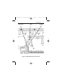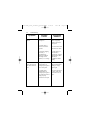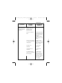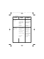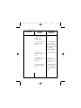
1
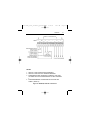
250-0280_rev1_readers_spreads.qxd 5/21/01 Models: BOSS04-D240AC-4Q BOSS04-D240AC-CM BOSS08-D240AC-4Q BOSS08-D240AC-CM BOSS15-115AC-4Q BOSS15-115AC-CM Page a USER’S MANUAL BOSS Series 2:03 PM BOSS Series Brushless Drives 250-0280_rev1_readers_spreads.qxd 5/21/01 2:03 PM Page b Copyright 2001 by Minarik Corporation All rights reserved. No part of this manual may be reproduced or transmitted in any form without written permission from Minarik Corporation. The information and technical data in this manual are subject to change without notice. Minarik Corporation and its Divisions make no warranty of any kind with respect to this material, including, but not limited to, the implied warranties of its merchantability and fitness for a given purpose. Minarik Corporation and its Divisions assume no responsibility for any errors that may appear in this manual and make no commitment to update or to keep current the information in this manual. Printed in the United States of America 250-0280_rev1_readers_spreads.qxd 5/21/01 2:03 PM Page i i Safety Warnings • This symbol denotes an important safety tip or warning. Please read these instructions carefully before performing any of the procedures contained in this manual. • Have a qualified electrical maintenance technician install, adjust, and service this equipment. Follow the National Electrical Code and all other applicable electrical and safety codes, including the provisions of the Occupational Safety and Health Act (OSHA) when installing equipment. • Reduce the chance of an electrical fire, shock, or explosion by proper grounding, over current protection, thermal protection, and enclosure. Follow sound maintenance procedures. Warning Although the drive includes protective circuitry to prevent damage in the event of an accidental short circuit of the armature, it is not fail-safe. It is possible for a drive to run at full speed as a result of a component failure. Install a master switch in the drive’s AC or DC voltage input line for stopping the drive in an emergency. Inadvertent grounding of drive inputs could result in damage to the drive. Avoid direct contact with the printed circuit board or with circuit elements to prevent the risk of serious injury or fatality. Use a non-metallic screwdriver for adjusting the calibration trimpots. Use insulated tools if working on this drive with power applied. 250-0280_rev1_readers_spreads.qxd 5/21/01 2:03 PM Page ii ii Introduction The BOSS series is a family of analog brushless servo controls. They are designed to be flexible and adaptable to a multitude of needs by using the “modular” concept. The modular concept has two parts: a motherboard and a daughter card. The motherboard contains power and motor connections. Each daughter card is designed to fit into the same motherboard, yet each daughter card is optimized for different applications. This allows you to customize your BOSS drive to suit your needs, unlike the standard “one size fits all” approach. The BOSS motherboard is stocked throughout the country. Each daughter card is packed separately as 4Q or CM. The BOSS-4Q does not have isolation, and requires applicationspecific calibration. The BOSS-CM is designed exclusively to follow a front-end servo controller. It is a current-mode drive with optical isolation and requires no calibration except for a simple current-limit adjustment. 250-0280_rev1_readers_spreads.qxd 5/21/01 2:03 PM Page iii iii 250-0280_rev1_readers_spreads.qxd 5/21/01 2:03 PM Page iv iv Contents Specifications 1 Dimensions 2 Installation 4 Drive mounting . . . . . . . . . . . . . . . . . . . . . . . . . . . . . . . . . . . . . . . . . . . . .4 Wiring . . . . . . . . . . . . . . . . . . . . . . . . . . . . . . . . . . . . . . . . . . . . . . . . . . . . .5 Shielding guidelines . . . . . . . . . . . . . . . . . . . . . . . . . . . . . . . . . . . . . . . .6 Fusing . . . . . . . . . . . . . . . . . . . . . . . . . . . . . . . . . . . . . . . . . . . . . . . . . . . .7 Plug-in card mounting . . . . . . . . . . . . . . . . . . . . . . . . . . . . . . . . . . . . . . . . .8 Speed adjust potentiometer mounting . . . . . . . . . . . . . . . . . . . . . . . . . . . .10 Quick-connect terminal block . . . . . . . . . . . . . . . . . . . . . . . . . . . . . . . . . .11 Motherboard connections . . . . . . . . . . . . . . . . . . . . . . . . . . . . . . . . . . . . .12 Power connections . . . . . . . . . . . . . . . . . . . . . . . . . . . . . . . . . . . . . . .12 Line fusing . . . . . . . . . . . . . . . . . . . . . . . . . . . . . . . . . . . . . . . . . . . . . .13 Power switch . . . . . . . . . . . . . . . . . . . . . . . . . . . . . . . . . . . . . . . . . . . .13 Motor connections . . . . . . . . . . . . . . . . . . . . . . . . . . . . . . . . . . . . . . . .15 Regen dump circuit . . . . . . . . . . . . . . . . . . . . . . . . . . . . . . . . . . . . . . . . .16 Using the dump circuit with a DC power source . . . . . . . . . . . . . . . . . .16 BOSS-4Q Installation . . . . . . . . . . . . . . . . . . . . . . . . . . . . . . . . . . . . . . . .18 BOSS-4Q Terminal Descriptions . . . . . . . . . . . . . . . . . . . . . . . . . . . . .18 BOSS-4Q Plug-in card connections (TB501) . . . . . . . . . . . . . . . . . . . .20 ENABLE/DISABLE switch . . . . . . . . . . . . . . . . . . . . . . . . . . . . . . . .20 RUN/BRAKE switch . . . . . . . . . . . . . . . . . . . . . . . . . . . . . . . . . . . .20 FWD/REV switch . . . . . . . . . . . . . . . . . . . . . . . . . . . . . . . . . . . . . .20 Speed adjust potentiometer connections . . . . . . . . . . . . . . . . . . . . .20 Motor hall sensors . . . . . . . . . . . . . . . . . . . . . . . . . . . . . . . . . . . . . . . .22 Voltage follower . . . . . . . . . . . . . . . . . . . . . . . . . . . . . . . . . . . . . . . . . .24 Motor hall sensor header (SW502) . . . . . . . . . . . . . . . . . . . . . . . . . . .25 Mode select switches (SW501) . . . . . . . . . . . . . . . . . . . . . . . . . . . . . . .26 TB504 Drive Diagnostics . . . . . . . . . . . . . . . . . . . . . . . . . . . . . . . . . . .28 250-0280_rev1_readers_spreads.qxd 5/21/01 2:03 PM Page v v Contents BOSS-CM Installation . . . . . . . . . . . . . . . . . . . . BOSS-CM Terminal Descriptions . . . . . . . . . . BOSS-CM Plug-in card connections to TB501 ENABLE/DISABLE switch . . . . . . . . . . . . . DIR switch . . . . . . . . . . . . . . . . . . . . . . . . Speed adjust potentiometer connections . . Motor hall sensors . . . . . . . . . . . . . . . . . . . . . BOSS-CM Jumper Settings . . . . . . . . . . . . . . Hall Sensor Spacing (J501) . . . . . . . . . . . . PWM/VDC (J502) . . . . . . . . . . . . . . . . . . . . . . . . . . . . . . . . . . . . . . . . . . . . . . . . . . . . . . . . . . . . . . . . . . . . . . . . . . . . . . . . . . . . . . . . . . . . . . . . . . . . . . . . . . . . . . . . . . . . . . . . . . . . . . . . . . . . . . . . . . . . . . . . . . . . . . . . . . . . . . . . . . . . . . . . . .31 .31 .33 .33 .33 .33 .37 .39 .39 .40 Operation BOSS-4Q Operation . . . . . . . . . . . . . . . . . . . . . . . . . . . . . . Before applying power . . . . . . . . . . . . . . . . . . . . . . . . . . . Startup . . . . . . . . . . . . . . . . . . . . . . . . . . . . . . . . . . . . . . To reverse motor direction: . . . . . . . . . . . . . . . . . . . . . BOSS-CM Operation . . . . . . . . . . . . . . . . . . . . . . . . . . . . . . Operating Mode . . . . . . . . . . . . . . . . . . . . . . . . . . . . . . . . Before applying power . . . . . . . . . . . . . . . . . . . . . . . . . . . Startup . . . . . . . . . . . . . . . . . . . . . . . . . . . . . . . . . . . . . . To reverse motor direction . . . . . . . . . . . . . . . . . . . . . . Starting and Stopping Methods . . . . . . . . . . . . . . . . . . . . . . . Line starting and line stopping . . . . . . . . . . . . . . . . . . . . . To brake the motor (BOSS-4Q series drives only) . . . . . . To coast the motor to a stop without disconnecting power: . . . . . . . . . . . . . . . . . . . . . . . . . . . . . . . . . . . . . . . . . . . . . . . . . . . . . . . . . . . . . . . . . . . . . . . . . . . . . . . . . . . . . . . . . . . . . . . . . . . . . . . . . . . . . . . . . . . . . 41 .41 .41 .42 .42 .43 .43 .43 .44 .44 .45 .45 .45 .46 Calibration BOSS-4Q Calibration . . . . . . . . . . . . . . . . . . . . . . . . . BOSS-4Q calibration procedure . . . . . . . . . . . . . . . MINIMUM SPEED (MIN SPEED) . . . . . . . . . . . ZERO OFFSET (OS) . . . . . . . . . . . . . . . . . . . . FORWARD MAXIMUM SPEED (FWD MAXSPD) REVERSE MAXIMUM SPEED (REV MAXSPD) ACCELERATION (ACCEL) . . . . . . . . . . . . . . . . . . . . . . . . . . . . . . . . . . . . . . . . . . . . . . . . . . . . . . . . . . . . . . . . . . . . . . . . . . . . . . . 47 .47 .49 .50 .50 .51 .51 .52 . . . . . . . . . . . . . . . . . . . .. .. . . . . . . . . . . . . . . . . . . . . . . . . . . . . . . . . . . . . . . . . . 250-0280_rev1_readers_spreads.qxd vi 5/21/01 2:03 PM Page vi Contents DECELERATION (DECEL) . . . . . . . . . . . . . GAIN . . . . . . . . . . . . . . . . . . . . . . . . . . . . . FORWARD AND REVERSE TORQUE LIMIT (FWD TQLIM AND REV TQLIM) . . . . . . . . TACHOGENERATOR (TACH) . . . . . . . . . . . BOSS-CM Calibration . . . . . . . . . . . . . . . . . . . . . CURRENT LIMIT . . . . . . . . . . . . . . . . . . . . . . . Troubleshooting Before troubleshooting . . . . . . . . . . . . . . . . . . . . . BOSS-4Q Diagnostic LEDs . . . . . . . . . . . . . . . . . Diagnostic LEDs on the BOSS-4Q plug-in card: POWER ON . . . . . . . . . . . . . . . . . . . . . . . . FAULT . . . . . . . . . . . . . . . . . . . . . . . . . . . . Diagnostic LEDs on the motherboard: . . . . . . . BUS LIMIT . . . . . . . . . . . . . . . . . . . . . . . . . BOSS-CM Diagnostic LEDs . . . . . . . . . . . . . . . . . Diagnostic LEDs on the BOSS-CM plug-in card: POWER ON . . . . . . . . . . . . . . . . . . . . . . . . FAULT . . . . . . . . . . . . . . . . . . . . . . . . . . . . Diagnostic LEDs on the motherboard: . . . . . . . BUS LIMIT . . . . . . . . . . . . . . . . . . . . . . . . . BOSS Commutation Sequence Diagram . . . . . . . CE Compliance AC Line Filters . . . . . . Connections . . . . . . . CE Filter Part Numbers Enclosure . . . . . . . . . Unconditional Warranty ... ... .. ... . . . . . . . . . . . . . . . . . . . . . . . . . . . . . . . . . . . . . . . . . . . . . . . . . . . . . . . . . . . . . . . . . . . . . . . . . . . . . . . . . . . . . . . . . .53 . . . . . . . . . . . . . . . . . .53 . . . . . . . . . . . . . . . . . . . . . . . . . . . . . . . . . . . . . . . . . . . . . . . . . . . . . . . . . . . . . . . . . . . . .54 .56 .58 .59 . . . . . . . . . . . . . . . . . . . . . . . . . . . . . . . . . . . . . . . . . . . . . . . . . . . . . . . . . . . . . . . . . . . . . . . . . . . . . . . . . . . . . . . . . . . . . . . . . . . . . . . . . . . . . . . . . . . . . . . . . . . . . . . . . . . . . . . . . . . . . . . . . . . . . . . . . . . . . . . . . . . . . . . . . . . . . . . . . . . . . . . . . . . . . . . . . . . . . . . . . . . . . . . . . . . . . . . . . . . . . . . . . . . . . . . . . . . . . 61 .61 .62 .62 .62 .62 .62 .62 .64 .64 .64 .64 .64 .64 .72 . . . . . . . . . . . . . . . . . . . . . . . . . . . . . . . . . . . . . . . . . . . . . . . . . . . . . . . . . . . . . . . . . . . . 73 .74 .75 .76 .76 inside back cover 250-0280_rev1_readers_spreads.qxd 5/21/01 2:03 PM Page vii vii Illustrations Figure Figure Figure Figure Figure Figure 1. 2. 3. 4. 5. 6. Figure Figure Figure Figure Figure Figure Figure Figure Figure Figure 7. 8. 9. 10. 15. 16. 17. 18. 15. 16. Figure Figure Figure Figure Figure Figure Figure Figure Figure Figure Figure Figure 17. 18. 19. 20. 21. 22. 23. 24. 25. 26. 27. 28. BOSS Series Dimensions . . . . . . . . . . . . . . . . . . . . . . . . . . . . . . .2 BOSS DB Regen Dump Circuit Dimensions . . . . . . . . . . . . . . . . . .3 Plug-In Card Installation . . . . . . . . . . . . . . . . . . . . . . . . . . . . . . . .9 Speed Adjust Potentiometer Mounting . . . . . . . . . . . . . . . . . . . . .10 Quick-Connect Terminal Plug . . . . . . . . . . . . . . . . . . . . . . . . . . . .11 Motherboard Connections for (a) DC input voltage and (b) AC input voltage . . . . . . . . . . . . . . . . . . . . . . . . . . . . . . . . . . .14 Motherboard Connections for Three-Phase Motor . . . . . . . . . . . .15 Regen Dump Circuit Connections . . . . . . . . . . . . . . . . . . . . . . . .17 BOSS-4Q Terminal Connections . . . . . . . . . . . . . . . . . . . . . . . . .21 BOSS-4Q Sensor Connections . . . . . . . . . . . . . . . . . . . . . . . . . .23 BOSS-4Q Voltage Follower Connections . . . . . . . . . . . . . . . . . . .24 BOSS-4Q Motor Hall Sensor Header . . . . . . . . . . . . . . . . . . . . . .25 BOSS-4Q Mode Select Switches . . . . . . . . . . . . . . . . . . . . . . . . .27 BOSS-4Q TB504 Pin Assignments . . . . . . . . . . . . . . . . . . . . . . .28 BOSS-CM Terminal Connections to TB501 . . . . . . . . . . . . . . . . .35 Reference Potentiometer Connection for (a) Bidirectional and (b) Unidirectional Operation . . . . . . . . . . . . .36 BOSS-CM External Sensor Connections . . . . . . . . . . . . . . . . . . .38 BOSS-CM Jumper Locations . . . . . . . . . . . . . . . . . . . . . . . . . . . .39 BOSS-CM Hall Sensor Spacer Settings (J501) . . . . . . . . . . . . . .40 BOSS-CM PWM/VDC Jumper Settings (J502) . . . . . . . . . . . . . . .40 BOSS-4Q Calibration Trimpot DIP Switch and Header Layout . . .48 BOSS-4Q Mode Select Switch Settings . . . . . . . . . . . . . . . . . . .57 BOSS-CM Calibration Trimpot Layout . . . . . . . . . . . . . . . . . . . . .58 BOSS-4Q Diagnostic LED Location . . . . . . . . . . . . . . . . . . . . . . .63 BOSS-CM Diagnostic LED Location . . . . . . . . . . . . . . . . . . . . . .65 Commutation Sequence Diagram . . . . . . . . . . . . . . . . . . . . . . . .72 BOSS Connections for CE Compliance . . . . . . . . . . . . . . . . . . . .76 BOSS Shielding Connections for CE Compliance . . . . . . . . . . . .77 250-0280_rev1_readers_spreads.qxd 5/21/01 2:03 PM Page viii viii Tables Table Table Table Table Table 1. 2. 3. 4. 5. Recommended Replacement Line Fuse Sizes . . . . . . . . . . . . . . .7 BOSS-4Q ENABLE/BRAKE Configuration Options . . . . . . . . . . .22 Mode select switch settings . . . . . . . . . . . . . . . . . . . . . . . . . . . .27 Drive Diagnostics (All signals referenced to pin 4) . . . . . . . . . . . .29 CE Compliance Part Numbers . . . . . . . . . . . . . . . . . . . . . . . . . .76 250-0280_rev1_readers_spreads.qxd 5/21/01 2:03 PM Page 1 1 Specifications Maximum AC DC Maximum Phase Current Line Input Output Voltage Drive (AC Amps) Voltage Range Voltage Range (VAC) BOSS04-D240AC 4 90 - 240 100 - 360 240 BOSS08-D240AC 8 90 - 240 100 - 360 240 BOSS15-115AC 15 90 - 130 100 - 180 130 AC Input Voltage Tolerance ± 10%, 50 – 60 Hz Maximum Phase Current Limit 1.5 times Maximum Phase Current (continuous) Peak Phase Current Limit 2 times Maximum Phase Current (for 1 second) Acceleration Time Range† 0.5 – 6 seconds Deceleration Time Range† 0.5 – 6 seconds Speed Range* 80:1 Speed Regulation (typical) 0.06% of base speed Speed Adjust Potentiometer 10K ohms Analog Input Voltage Range** 0 – 10 VDC Input Impedance 60K ohms Power Device Switching Frequency (6–step, trapezoidal) 22 kHz Vibration 0.5G max (20 – 50 Hz) 0.1G max (>50 Hz) Weight 2 lb Ambient Operating Temperature Range 0 – 40º C †Acceleration and deceleration times for BOSS-4Q only. *Speed range is based on 8000 RPM motor. Minimum recommended speed is 100 RPM. **Voltage input must be isolated on BOSS-4Q series drives. BOSS-CM inputs are isolated and do not require additional isolation. 250-0280_rev1_readers_spreads.qxd 5/21/01 2 Dimensions Drive BOSSxx-115AC BOSSxx-D240AC Dimension “A” 2.62 [67] 3.87 [98] All Dimensions in Inches [Millimeters] Figure 1. BOSS Series Dimensions 2:03 PM Page 2 250-0280_rev1_readers_spreads.qxd 5/21/01 2:03 PM Dimensions All Dimensions in Inches [Millimeters] Figure 2. BOSS DB Regen Dump Circuit Dimensions Page 3 3 250-0280_rev1_readers_spreads.qxd 5/21/01 2:03 PM Page 4 4 Installation Drive mounting Warning Do not install, rewire, or remove this control with input power applied. Doing so may cause fire or serious injury. Make sure you have read and understood the Safety Warnings before attempting installation. • Drive components are sensitive to electrostatic fields. Avoid contact with the circuit board directly. Hold the drive by the chassis only. • Protect the drive from dirt, moisture, and accidental contact. Provide sufficient room for access to the terminal block and calibration trimpots. • Mount the drive away from other heat sources. Operate the drive within the specified ambient operating temperature range. • Prevent loose connections by avoiding excessive vibration of the drive. • Mount drive with its board in either a horizontal or vertical plane. Six 0.19 in. (5 mm) wide slots in the chassis accept #8 pan head screws. Fasten either the large base or the narrow flange of the chassis to the subplate. • The chassis does not have to be earth grounded. If you choose to ground the chassis, use a star washer beneath the head of at least one of the mounting screws to penetrate the anodized chassis surface and to reach bare metal. 250-0280_rev1_readers_spreads.qxd 5/21/01 2:03 PM Page 5 Installation Wiring 쇵 Warning Do not install, remove, or rewire this equipment with power applied. Failure to heed this warning may result in fire, explosion, or serious injury. Circuit potentials are at 115 or 240 VAC above ground. To prevent the risk of injury or fatality, avoid direct contact with the printed circuit board or with circuit elements. Do not disconnect any of the motor leads from the drive unless power is removed. Opening any one motor lead may destroy the drive. • Use 16 AWG wire for the AC or DC voltage input wiring (L1 and L2 or +VDC and -VDC), regen dump circuit, and motor wiring (U, V, W). Use 18-20 AWG wire for speed adjust potentiometer wiring. 5 250-0280_rev1_readers_spreads.qxd 6 5/21/01 2:03 PM Page 6 Installation Shielding guidelines Warning Under no circumstances should power and logic leads be bundled together. Induced voltage can cause unpredictable behavior in any electronic device, including motor controls. Minarik recommends shielding all leads. If shielding is not practical, the user should twist all logic leads with themselves to minimize induced noise. It may be necessary to earth ground the shielded cable. If noise is produced by devices other than the drive, ground the shield at the drive end. If noise is generated by a device on the drive, ground the shield at the end away from the drive. Do not ground both ends of the shield. If the drive continues to pick up noise after grounding the shield, it may be necessary to add AC line filtering devices, or to mount the drive in a less noisy environment. 250-0280_rev1_readers_spreads.qxd 5/21/01 2:03 PM Page 7 Installation Fusing An external line fuse must be installed on all BOSS series drives. Connect the external line fuse in series with the AC voltage input or DC voltage input, whichever is used. Do not install a fuse on L2 unless the input voltage is 240 VAC. See motherboard connections (Figure 6) on page 14. Table 1 lists the recommended line fuse sizes. Use fast acting fuses rated for 250 VAC or higher. Table 1. Recommended Line Fuse Sizes Model Line Fuse Size Series (AC Amps) BOSS04 10 BOSS08 15 BOSS15 25 7 250-0280_rev1_readers_spreads.qxd 8 5/21/01 2:03 PM Page 8 Installation Plug-in card mounting Warning Make sure AC or DC line voltage input is disconnected for 30 seconds before installing or removing the plug-in card. To mount the plug-in card to the motherboard, line up the motherboard docking pins to the docking holes (Figure 3). Align the header pins on the plug-in card with the corresponding header sockets on the motherboard. Fasten the header pins into the header sockets until secure. The docking pins will lock the plug-in card into place when the header pins are correctly mounted into the header sockets. 250-0280_rev1_readers_spreads.qxd 5/21/01 2:03 PM Page 9 Installation (Make sure AC or DC voltage input is removed for 30 seconds before installing or removing plug-in card) Figure 3. Plug-In Card Installation 9 250-0280_rev1_readers_spreads.qxd 10 5/21/01 2:03 PM Page 10 Installation Speed adjust potentiometer mounting Warning Be sure that the potentiometer tabs do not make contact with the potentiometer enclosure. Grounding the input will cause damage to the drive. Mount the speed adjust potentiometer through a 0.38-inch (1.0 cm) hole with the hardware provided (Figure 4). Install the circular insulating disk between the panel and the 10K ohm speed adjust potentiometer. Twist the speed adjust potentiometer wire to avoid picking up unwanted electrical noise. If potentiometer leads are longer than 18 inches (46 cm), use shielded cable. Figure 4. Speed Adjust Potentiometer Mounting 250-0280_rev1_readers_spreads.qxd 5/21/01 2:03 PM Installation Page 11 11 Quick-connect terminal block The quick-connect terminal block is composed of a header block and terminal plug. The removable terminal plug, Minarik part number 160-0136, connects to the header block as shown in Figure 5. To use the quick-connect terminal block: 1. 2. 3. 4. 5. 6. Carefully pull terminal plug from header block. With a small flat-head screwdriver, turn terminal plug screw counterclockwise to open wire clamp. Insert stripped wire into the large opening in front of the plug. Turn the terminal plug screw clockwise to clamp the wire. Repeat steps 2–4 for each terminal until all connections are made. Insert plug into header block until securely fastened. Figure 5. Quick-Connect Terminal Plug 250-0280_rev1_readers_spreads.qxd 12 5/21/01 2:03 PM Page 12 Installation Motherboard connections Warning Do not install, remove, or connect this equipment with power applied. Failure to heed this directive may result in fire or serious injury. Minarik strongly recommends the installation of a master power switch in the voltage input line. The switch contacts should be rated at a minimum of 200% of motor nameplate current and 150% of input voltage. Do not connect DC and AC power inputs at the same time. Applying AC and DC power simultaneously will destroy the drive and may result in fire or serious injury. Power connections See Figure 6 (page 14) for motherboard connections. Connect the AC voltage source to L1 and L2 if using an AC voltage source. If the drive is being powered by a DC voltage source, connect the DC voltage source to +VDC and –VDC. Do not connect AC and DC voltage sources at the same time! 250-0280_rev1_readers_spreads.qxd 5/21/01 2:03 PM Installation Page 13 13 Line fusing Connect an external fuse between the drive and master stop switch as shown in Figure 6 (page 14). Install the switch between the external fuse and AC or DC power input as shown. Place a line fuse on +VDC if using DC input voltage, or L1 if the AC input voltage is 115 VAC. Do not add a line fuse to L2 unless the input voltage is 240 VAC. Refer to Table 1 (page 7) for replacement line fuse sizes. Power switch Warning Minarik strongly recommends the installation of a master power switch in the voltage input line. The switch contacts should be rated at a minimum of 200% of motor nameplate current and 250 volts. Install a master power switch in the voltage input line, as shown in Figure 6 (page 14). The switch contacts should be rated at a minimum of 200% of motor nameplate current and 250 volts. 250-0280_rev1_readers_spreads.qxd 14 5/21/01 2:03 PM Page 14 Installation OR Warning Do not connect AC and DC voltage at the same time. This will destroy the BOSS drive and may result in fire or serious personal injury. Figure 6. Motherboard Connections for (a) DC input voltage and (b) AC input voltage 250-0280_rev1_readers_spreads.qxd 5/21/01 2:03 PM Installation Motor connections Connect a three-phase motor to the motherboard as shown in Figure 7. Ensure that the motor’s voltage and current ratings are compatible with the drive ratings before making any connections. Figure 7. Motherboard Connections for Three-Phase Motor Page 15 15 250-0280_rev1_readers_spreads.qxd 16 5/21/01 2:03 PM Page 16 Installation Regen dump circuit The regen dump circuit is recommended for all BOSS Series drives. Regenerative loads may cause the bus voltage to increase. The regen dump circuit prevents the voltage across the bus capacitors from exceeding their voltage rating. Connect the +BUS terminal on the regen dump circuit to the +VDC terminal on the BOSS drive motherboard. Connect the BUS terminal on the regen dump circuit to the –VDC terminal on the BOSS drive motherboard. See Figure 8 for regen dump circuit connections. Frequent regenerative reversing requires additional power resistors to be added to the regen dump circuit. Contact the Minarik factory for more assistance. Using the dump circuit with a DC power source If you use a DC power source and you wish to use the regen dump circuit, you must connect the power source to the BOSS drive L1 and L2 terminals as shown in Figure 8. Connect the positive (+) lead from the DC power source to the L1 terminal on the BOSS drive motherboard. Connect the negative (or COM) lead from the DC power source to the L2 terminal on the BOSS drive motherboard. 250-0280_rev1_readers_spreads.qxd 5/21/01 2:03 PM Installation Page 17 17 BOSS SERIES DRIVE REGEN DUMP CIRCUIT NOTE: CONNECTIONS SHOWN ARE FOR DC POWER SOURCE. REFER TO FIGURE 6 (PAGE 14) FOR AC POWER SOURCE CONNECTIONS. Figure 8. Regen Dump Circuit Connections 250-0280_rev1_readers_spreads.qxd 18 5/21/01 2:03 PM Page 18 Installation BOSS-4Q Installation BOSS-4Q Terminal Descriptions COM (terminals 1 and 13) Warning Do not connect these terminals to earth ground. Circuit common. ENABLE (terminal 2) Short to COM to run the motor; leave open to coast to a stop. BRAKE (terminal 3) Short to COM to brake the motor; leave open to run the motor. FWD/REV (terminal 4) Short to COM to run the motor in the reverse direction; leave open to run the motor in the forward direction. +V POT (terminal 5) Floating +10 VDC reference for 10K ohm speed adjust potentiometer. SPD IN (terminal 6) Accepts floating (ungrounded) –10VDC to +10 VDC reference or 10K ohm speed adjust potentiometer wiper. 250-0280_rev1_readers_spreads.qxd 5/21/01 2:03 PM Installation Page 19 19 –V POT (terminal 7) Floating –10 VDC reference for 10K ohm speed adjust potentiometer. + 15 (terminal 8) Floating +15 VDC supply (25 mA maximum). NOTE: This terminal is not identified on the printed circuit board (PCB) or terminal block. – 15 (terminal 9) Floating –15 VDC supply (25 mA maximum). NOTE: This terminal is not identified on the printed circuit board (PCB) or terminal block. HALL C,B,A (terminals 10, 11 and 12) Inputs from motor hall sensors. + 5 VDC Vref (terminal 14) Warning The +5 VDC supply has a maximum capacity of 20 mADC. Please ensure that any sensor package connected to this terminal does not draw more than 20 mADC. If the sensor package draws more than 20 mADC, it must be connected to an external, regulated power supply as shown in Figure 10 (page 23). Floating (isolated) +5 VDC, 20 mA supply for external sensors. 250-0280_rev1_readers_spreads.qxd 20 5/21/01 2:03 PM Page 20 Installation BOSS-4Q Plug-in card connections (TB501) ENABLE/DISABLE switch Connect a single-pole, single-throw switch between the COM and ENABLE terminals (terminals 1 and 2) of TB501 as shown in Figure 9. Open the switch to coast the motor to a stop. Close the switch to accelerate to set speed. RUN/BRAKE switch Connect a single-pole, single-throw switch between the COM and BRAKE terminals (terminals 1 and 3) of TB501 as shown in Figure 9. Close the switch to brake the motor to a stop. Open the switch to accelerate to set speed. FWD/REV switch Connect a single-pole, single-throw switch between the COM and FWD/REV terminals (terminals 1 and 4) of TB501 as shown in Figure 9. Open the switch to run the motor in the forward direction. Close the switch to run the motor in the reverse direction. Speed adjust potentiometer connections Connect a 10K ohm, 5W speed adjust potentiometer as shown in Figure 9 for unidirectional (one-way) operation in the forward direction. For unidirectional operation in the reverse direction, connect the CW terminal to -VPOT (terminal 7) of TB501 and connect the CCW terminal to COM (terminal 1) of TB501. For bidirectional (two-way) operation, connect the CCW terminal to -VPOT (terminal 7) of TB501 . The motor will stop when the potentiometer is in the middle of its travel. 250-0280_rev1_readers_spreads.qxd 5/21/01 2:03 PM Page 21 Installation TB501 NOTES: 1. SEE PG 72 FOR COMMUTATION SEQUENCE 2. SEE PG 22 FOR USE WITH SENSOR FEEDBACK 3. FOR BIDIRECTIONAL OPERATION, CONNECT CCW LEAD OF SPEED ADJUST POTENTIOMETER TO TB501 TERMINAL 7. 4. FOR ENABLE/BRAKE CONFIGURATION OPTIONS SEE TABLE 2 (PAGE 22). Figure 9. BOSS-4Q Terminal Connections 21 250-0280_rev1_readers_spreads.qxd 22 5/21/01 2:03 PM Page 22 Installation Table 2. BOSS-4Q ENABLE/BRAKE Configuration Options Enable Switch Position (Terminals 1 – 2) CLOSED CLOSED OPEN OPEN Brake Switch Position (Terminals 1 – 3) Result OPEN RUN CLOSED REGEN BRAKE OPEN COAST TO STOP CLOSED COAST TO STOP Motor hall sensors Warning BOSS series drives provide a +5 VDC supply to external sensors. This voltage has a maximum capacity of 20 mADC. To avoid damage to the drive, ensure that any sensor package connected to this terminal does not draw more than 20 mADC. Connect an external sensor, such as a hall motor sensor, as shown in Figure 10. Connect the sensor to TB501 terminals 13 (common) and 14 (+5 VDC). If the sensor draws more than 20 mADC, an external power supply must be used to avoid damage to the BOSS drive. 250-0280_rev1_readers_spreads.qxd 5/21/01 2:03 PM Installation Figure 10. BOSS-4Q Sensor Connections Page 23 23 250-0280_rev1_readers_spreads.qxd 24 5/21/01 2:03 PM Page 24 Installation Voltage follower Instead of using a speed adjust potentiometer, BOSS-4Q series drives may be wired to follow a floating (differential) –10 VDC to +10 VDC signal that is isolated from earth ground. Connect a voltage signal to terminals 1 and 6 (see Figure 15 for connections). Figure 15. BOSS-4Q Voltage Follower Connections 250-0280_rev1_readers_spreads.qxd 5/21/01 2:03 PM Installation Page 25 25 Motor hall sensor header (SW502) Set the motor hall sensor header according to the hall effect feedback spacing (see Figure 16 for location). Jumper SW502 if the hall effect feedback spacing is 120°. Do not add a jumper if the hall effect feedback spacing is 60°. Hall sensors are not allowed to be advanced or retarded. To reverse motor rotation, the BOSS drive switches hall sensor sequence, eliminating the need to switch motor leads. Motor Hall Sensor Header SW502 Figure 16. BOSS-4Q Motor Hall Sensor Header 250-0280_rev1_readers_spreads.qxd 26 5/21/01 2:03 PM Page 26 Installation Mode select switches (SW501) Warning Be sure that drive power is removed before changing any mode select switch settings. Unpredictable behavior may occur if this warning is not followed. The mode select switches set the BOSS drive to one of the four operating modes: 1. 2. 3. 4. Voltage Mode (no internal velocity loop) Velocity Mode (voltage mode plus internal velocity loop) Tachometer Feedback Mode Current Mode (no voltage or velocity loops) Set the mode select switches according to the appropriate operating mode. Refer to Table 3 for mode select switch settings, and Figure 17 for mode select switch location. 250-0280_rev1_readers_spreads.qxd 5/21/01 2:03 PM Installation Table 3. Mode select switch settings Operating Modes Voltage Mode (no internal velocity loop) Velocity Mode (Voltage Mode plus internal velocity loop) Tachometer Feedback Mode Current Mode X = Don’t care. Mode Select Switch 1 2 3 4 ON OFF OFF ON ON OFF ON ON ON OFF OFF ON X X OFF X SW501 Figure 17. BOSS-4Q Mode Select Switches Page 27 27 250-0280_rev1_readers_spreads.qxd 28 5/21/01 2:03 PM Page 28 Installation TB504 Drive Diagnostics TB504 is a 10-pin male connector used for non-isolated drive diagnostics outputs. See Figure 18 for connector location and Table 4 for pin functions. PIN 1 PIN 2 PIN 10 Figure 18. BOSS-4Q TB504 Pin Assignments PIN 9 250-0280_rev1_readers_spreads.qxd 5/21/01 2:03 PM Installation Table 4. Drive Diagnostics (All signals referenced to pin 4) Pins Description Pin 1Tachometer Out 12 pulses per revolution, 5 VDC square wave output; proportional to motor speed. Pin 2Run/Stop 0 VDC when Run/Stop switch is set for run; 5 VDC when Run/Stop switch is set for stop. Pin 3Fault Out 5 VDC when the drive is in a fault condition. Pin 4Circuit Common: Do not connect to earth ground! Circuit common. All other pins are referenced to circuit common. Pin 5IAVG Out 0–10 VDC output corresponding to the sum of all AC phase currents (AC phase currents are rectified, summed, then scaled to 0–10 VDC output). Waveform 0 volts. Page 29 29 250-0280_rev1_readers_spreads.qxd 30 5/21/01 2:03 PM Installation Table 4. Drive Diagnostics (All signals referenced to pin 4) (cont.) Pins Description Pin 6AC Current Phase A AC current in phase A is converted to voltage output (500 mV per amp AC). Pin 7AC Current Phase B AC current in phase B is converted to voltage output (500 mV per amp AC). Pin 8AC Current Phase C AC current in phase C is converted to voltage output (500 mV per amp AC). Pin 9 and 10 (not used) No function Waveform None. Page 30 250-0280_rev1_readers_spreads.qxd 5/21/01 2:03 PM Page 31 Installation 31 BOSS-CM Installation BOSS-CM Terminal Descriptions COM (terminals 1 and 13) Warning Do not connect these terminals to earth ground. Circuit common. ENABLE (terminal 2) Short to COM to run the motor; leave open to coast to a stop. PWM IN (terminal 3) Accepts a square-wave +5 VDC PWM input from an external signal source. DIR (terminal 4) Short to COM to run the motor in the reverse direction; leave open to run the motor in the forward direction. + REF IN (terminal 5) Accepts floating (ungrounded) –10 VDC to +10 VDC voltage signal. – REF IN (terminal 6) Acts as signal common for reference voltage applied at terminal 5. Connect to COM when using voltage signal input at terminal 5. 250-0280_rev1_readers_spreads.qxd 32 5/21/01 2:03 PM Page 32 Installation +10 VDC (terminal 7) + 10 VDC reference voltage output for reference potentiometer. See Figure 22 (page 46) and Figure 23 (page 47). – 10 VDC (terminal 8) – 10 VDC reference voltage output for reference potentiometer. See Figure 22 (page 46) and Figure 23 (page 47). FAULT OUT (terminal 9) Drive status signal to controller. HALL C,B,A (terminals 10, 11 and 12) Inputs from motor hall sensors. + 5 VDC Vref (terminal 14) Warning The +5 VDC supply has a maximum capacity of 20 mADC. Please ensure that any sensor package connected to this terminal does not draw more than 20 mADC. If the sensor package draws more than 20 mADC, it must be connected to an external, regulated power supply as shown in Figure 14 (page 28). Floating (isolated) +5 VDC, 20 mA supply for external sensors. 250-0280_rev1_readers_spreads.qxd 5/21/01 2:03 PM Page 33 Installation 33 BOSS-CM Plug-in card connections to TB501 ENABLE/DISABLE switch Connect a single-pole, single-throw switch between the COM and ENABLE terminals (terminals 1 and 2) of TB501 as shown in Figure 6. Close the switch to coast the motor to a stop. Open the switch to accelerate to set speed. DIR switch Connect a single-pole, single-throw switch between the COM and DIR terminals (terminals 1 and 4) of TB501 as shown in Figure 6. Open the switch to run the motor in the forward direction. Close the switch to run the motor inthe reverse direction. Speed adjust potentiometer connections You can use an external reference potentiometer to control motor speed, instead of a PWM or analog voltage signal. The potentiometer may be connected for bidirectional (two-way) or unidirectional (one-way) operation. Bidirectional operation Connect a 10K ohm reference potentiometer as shown in Figure 16, page 36, for bidirectional operation. Connect the CW terminal on the reference potentiometer to TB501 terminal 7. Connect the CCW terminal to TB501 terminal 8. Connect the wiper terminal to TB501 terminal 5. 250-0280_rev1_readers_spreads.qxd 34 5/21/01 2:03 PM Page 34 Installation When the wiper is in the center position, the motor will not rotate. The motor will accelerate as the potentiometer is turned in either the forward or reverse direction. Unidirectional operation Connect the reference potentiometer as shown in Figure 16 (page 36) for unidirectional (one-way) operation. To operate in the forward direction, connect the CW terminal on the reference potentiometer to TB501 terminal 7. To operate in the reverse direction, connect the CW terminal to TB501 terminal 8. Connect the wiper terminal to TB501 terminal 5. 250-0280_rev1_readers_spreads.qxd 5/21/01 2:03 PM Installation NOTES: 1. CONNECT ENABLE/DISABLE SWITCH TO TERMINALS 1 AND 2 AS SHOWN. CLOSE TO ENABLE; OPEN TO DISABLE. 2. CONNECT DIR SWITCH TO TERMINALS 1 AND 4 AS SHOWN. OPEN FOR FORWARD DIRECTION; CLOSE TO REVERSE. 3. REFER TO PAGE 36 FOR REFERENCE POTENTIOMETER CONNECTIONS. 4. DO NOT CONNECT PWM AND ANALOG VOLTAGE INPUTS AT THE SAME TIME. Figure 15. BOSS-CM Terminal Connections to TB501 Page 35 35 250-0280_rev1_readers_spreads.qxd 36 5/21/01 2:03 PM Page 36 Installation A) BIDIRECTIONAL OPERATION CCW CCW B) UNIDIRECTIONAL OPERATION NOTE: FORWARD DIRECTION SHOWN. CONNECT CW TERMINAL OF POTENTIOMETER TO -10 VDC (TB501 TERMINAL 8) FOR OPERATION IN THE REVERSE DIRECTION. Figure 16. BOSS-CM Reference Potentiometer Connection for (a) Bidirectional and (b) Unidirectional Operation 250-0280_rev1_readers_spreads.qxd 5/21/01 2:03 PM Installation Page 37 37 Motor hall sensors Warning BOSS series drives provide a +5 VDC supply to external sensors. This voltage has a maximum capacity of 20 mADC. To avoid damage to the drive, ensure that any sensor package connected to this terminal does not draw more than 20 mADC. Connect an external sensor, such as hall motor sensor, as shown in Figure 17 (page 38). Connect the sensor to TB502 terminals 13 (common) and 14 (+5 VDC). If the sensor draws more than 20 mADC, an external power supply must be used to avoid damage to the BOSS drive. 250-0280_rev1_readers_spreads.qxd 38 5/21/01 2:03 PM Installation CONNECT SENSOR AS SHOWN IF SENSOR PACKAGE DRAWS LESS THAN 20 mA AT 5VDC CONNECT SENSOR AS SHOWN IF SENSOR PACKAGE DRAWS MORE THAN 20 mA AT 5VDC Figure 17. BOSS-CM External Sensor Connections Page 38 250-0280_rev1_readers_spreads.qxd 5/21/01 2:03 PM Page 39 Installation 39 BOSS-CM Jumper Settings BOSS-CM series drives contain two jumper switches, used to configure various outputs. Refer to Figure 18 for jumper locations. Hall Sensor Spacing (J501) Set the motor hall sensor header according to the hall effect feedback spacing (see Figure 18 for location). Jumper J501 if the hall effect feedback spacing is 120°. Do not add a jumper if the hall effect feedback spacing is 60°. The factory default is 120º (jumper installed). See Figure 19, page 40. J502 PWM/VDC INPUT SELECT J501 HALL SENSOR SPACING Figure 18. BOSS-CM Jumper Locations 250-0280_rev1_readers_spreads.qxd 40 5/21/01 2:03 PM Page 40 Installation 1 1 Figure 19. BOSS-CM Hall Sensor Spacer Settings (J501) PWM/VDC (J502) J502 sets the input signal as either an analog voltage signal, reference potentiometer, or PWM input (Figure 20). Jumper terminals 1 and 2 if the input is PWM. Jumper terminals 2 and 3 for analog voltage or reference potentiometer input. The factory default is for voltage signal input (terminals 2 and 3 jumpered). Figure 20. BOSS-CM PWM/VDC Jumper Settings (J502) 250-0280_rev1_readers_spreads.qxd 5/21/01 2:03 PM Page 41 41 Operation Warning Dangerous voltages exist on the drive when it is powered, and up to 30 seconds after power is removed and the motor stops. BE ALERT. High voltages can cause serious or fatal injury. For your safety, use personal protective equipment (PPE) when operating this drive. Be sure that drive power is removed before changing any mode select switch settings. Unpredictable behavior may occur if this warning is not followed. BOSS-4Q Operation Before applying power • Verify that no conductive material is present on the printed circuit board. • Verify that hall sensor spacing jumper SW502 is set to the proper position for your application. 250-0280_rev1_readers_spreads.qxd 42 5/21/01 2:03 PM Page 42 Operation Startup 1. 2. 3. 4. 5. 6. 7. Verify that no conductive material is present on the PCB. Check that the ENABLE switch is in the enable position (closed). If no switch is installed, ensure that a jumper is installed between the ENABLE and COM terminals of TB501. Check that the RUN/BRAKE switch is in the run position (open). If no switch is installed, ensure that there is no jumper between the BRAKE and COM terminals of TB501. Set the FWD/REV switch to the direction you want the motor to rotate upon startup. Ensure that mode select switch SW501 is properly set for your application. Apply AC voltage input or DC voltage input to the drive. Slowly advance the speed adjust potentiometer clockwise (CW) or increase the voltage signal. The motor slowly accelerates as the potentiometer is turned CW or the voltage is increased. Continue until the desired speed is reached. To reverse motor direction: Switch the FWD/REV switch to the opposite position. To prevent possible demagnetization of the motor, consider bringing the motor to a stop before reversing polarity. Once stopped, enable the drive or apply input power. 250-0280_rev1_readers_spreads.qxd 5/21/01 2:03 PM Operation Page 43 43 BOSS-CM Operation Operating Mode The BOSS-CM provides a current output proportional to the input signal, up to the threshold set by the CURRENT LIMIT trimpot. For example, if the input voltage range is 0-10 VDC, the BOSS-CM current output will be zero with 0 VDC input and maximum current (as defined by the CURRENT LIMIT trimpot setting) with a 10 VDC input. Before applying power • Verify that no conductive material is present on the printed circuit board. • Verify that hall sensor spacing jumper J501 and PWM/VDC input jumper J502 are set to the proper positions for your application. 250-0280_rev1_readers_spreads.qxd 44 5/21/01 2:03 PM Page 44 Operation Startup 1. 2. 3. 4. 5. 6. 7. Verify that no conductive material is present on the PCB. Check that the ENABLE switch is in the enable position (closed), or that a jumper has been installed beween the COM and ENABLE terminals (terminals 1 and 2) of TB501. Verify that hall sensor header J501 is in the desired position. Verify that PWM/VDC SELECT header J502 is in the desired position. Set the DIR switch to the direction you want the motor to rotate upon startup. Apply AC voltage input or DC voltage input to the drive. Slowly increase the reference signal. The motor slowly accelerates as the signal is increased. Continue until the desired speed is reached. To reverse motor direction Switch the DIR switch to the opposite position. To prevent possible demagnetization of the motor, consider bringing the motor to a stop before reversing polarity. Once stopped, enable the drive or apply input power. You may also apply a negative voltage signal at the REF IN inputs. Again, to prevent possible demagnetization of the motor, consider bringing the motor to a stop before reversing polarity. Once stopped, enable the drive or apply input power. 250-0280_rev1_readers_spreads.qxd 5/21/01 2:03 PM Operation Page 45 45 Starting and Stopping Methods Warning Decelerating to minimum speed, regenerative braking, or coasting to a stop is recommended for frequent starts and stops. Do not use any of these methods for emergency stopping. They may not stop a drive that is malfunctioning. Removing AC or DC power (both L1 and L2 or +VDC and -VDC) is the only acceptable method for emergency stopping. For this reason, Minarik strongly recommends installing an emergency stop switch on both power input leads (see Connections on page 14). Line starting and line stopping Line starting and line stopping (applying and removing AC or DC voltage input) is not recommended for frequent starting and stopping of the drive. It is the only recommended method for emergency stopping of the drive. When line voltage input is applied to the drive, the motor accelerates to the current level set by the external reference signal. When line voltage input is removed, the motor coasts to a stop. To brake the motor (BOSS-4Q series drives only) Close the BRAKE switch. 250-0280_rev1_readers_spreads.qxd 5/21/01 2:03 PM Page 46 46 To coast the motor to a stop without disconnecting power: Open the ENABLE switch. 250-0280_rev1_readers_spreads.qxd 5/21/01 2:03 PM Page 47 47 Calibration Warning Dangerous voltages exist on the drive when it is powered, and up to 30 seconds after power is removed and the motor stops. When possible, disconnect the voltage input from the drive before adjusting the trimpots. If the trimpots must be adjusted with power applied, use insulated tools and the appropriate personal protection equipment. BE ALERT. High voltages can cause serious or fatal injury. BOSS-4Q Calibration BOSS-4Q series drives have eleven user-adjustable trimpots. Each drive is factory calibrated to its maximum current rating. Readjust the calibration trimpot settings to accommodate lower current motors. All adjustments increase with CW rotation, and decrease with CCW rotation. Use a non-metallic screwdriver for calibration. Each trimpot is identified on the printed circuit board. 250-0280_rev1_readers_spreads.qxd 48 5/21/01 2:03 PM Page 48 Calibration TACHOGENERATOR HEADER SO501 (TACH IN) FORWARD MAXIMUM SPEED REVERSE MAXIMUM SPEED TEST POINT TP1 DECELERATION ACCELERATION IR COMP MINIMUM SPEED MODE SELECT SWITCHES REVERSE TORQUE LIMIT OFF SET FORWARD TORQUE LIMIT Figure 21. BOSS-4Q Calibration Trimpot, DIP Switch and Header Layout TACH GAIN 250-0280_rev1_readers_spreads.qxd 5/21/01 2:03 PM Calibration Page 49 49 BOSS-4Q calibration procedure 1. 2. Ensure that no power is applied to the drive. Set the ENABLE/DISABLE switch to the ENABLE position (closed), or install a jumper between the ENABLE and COM terminals on TB501. 3. Set the RUN/BRAKE switch to the RUN position (open), or remove the jumper between the BRAKE and COM terminals on TB501. 4. Set the DIR switch to the desired direction, or install or remove a jumper between the DIR and COM terminals, as required. 5. Set all trimpots except TACH, FWD TQ LIM and REV TQ LIM to the center of travel. 6. Set the FWD TQ LIM and REV TQ LIM trimpots full clockwise (CW). 7. Make no adjustment to TACH unless you use tachogenerator feedback. 8. Set the signal input (analog voltage signal or speed adjust potentiometer) to zero or minimum speed. 9. Apply power to the drive. 10. Calibrate the trimpots in the order shown, starting on page 50. 250-0280_rev1_readers_spreads.qxd 50 5/21/01 2:03 PM Page 50 Calibration MINIMUM SPEED (MIN SPEED) The MIN setting determines the minimum speed when the speed adjust potentiometer or voltage input signal is set for minimum speed. It is factory set to zero speed. To calibrate MIN SPD: 1. Set the MIN SPD trimpot to the center position (12 o’clock). 2. Set the speed adjust potentiometer or voltage input signal for minimum speed. 3. Adjust the MIN SPD trimpot to the desired minimum speed. ZERO OFFSET (OS) The OS setting adjusts the zero offset voltage in the internal velocity loop. This affects the gain circuit which controls motor gain. Calibrating OS requires a voltmeter to measure the zero offset voltage. To calibrate OS: 1. Verify that there is no load on the motor. 2. Run the motor at any arbitrary speed (for example, 1000 RPM). 3. Using a voltmeter, measure the voltage from circuit common to test point TP1. 4. Using a non-metallic screwdriver, calibrate the OS trimpot until the voltmeter reads approximately 0 VDC. 250-0280_rev1_readers_spreads.qxd 5/21/01 2:03 PM Calibration Page 51 51 FORWARD MAXIMUM SPEED (FWD MAXSPD) The FWD MAXSPD setting determines the maximum motor speed when the speed adjust potentiometer or voltage input signal is set for maximum forward speed. It is factory set for maximum rated motor speed. To calibrate FWD MAXSPD: 1. Set the FWD MAXSPD trimpot full CCW. 2. Set the DIR switch (if installed) to FWD. If no switch is installed, install a jumper between terminals 1 (COM) and 4 (DIR) of TB501 . 3. Set the speed adjust potentiometer or voltage input signal for maximum speed. 4. Adjust the FWD MAXSPD trimpot to the desired maximum speed. REVERSE MAXIMUM SPEED (REV MAXSPD) The REV MAXSPD setting determines the maximum motor speed when the speed adjust potentiometer or voltage input signal is set for maximum reverse speed. It is factory set for maximum rated motor speed. To calibrate REV MAXSPD: 1. Set the REV MAXSPD trimpot full CCW. 2. Set the DIR switch (if installed) to REV. If no switch is installed, remove the jumper between terminals 1 (COM) and 4 (DIR) of TB501 . 3. Set the speed adjust potentiometer or voltage input signal for maximum speed. 4. Adjust the REV MAXSPD trimpot to the desired maximum speed. 250-0280_rev1_readers_spreads.qxd 52 5/21/01 2:03 PM Page 52 Calibration ACCELERATION (ACCEL) The ACCEL setting determines the time the motor takes to ramp to a higher speed in the forward direction or a lower speed in the reverse direction. ACCEL is factory set for the fastest acceleration time (full CCW). To calibrate ACCEL: 1. Set the speed adjust potentiometer or voltage input signal for minimum speed. The motor should run at minimum speed. 2. the speed adjust potentiometer or voltage input signal to maximum forward speed, and measure the time it takes the motor to go from minimum to maximum speed. 3. If the time measured in step 2 is not the desired acceleration time, turn the ACCEL trimpot CW for a slower acceleration time, or CCW for a faster acceleration time. Repeat steps 1 through 3 until the acceleration time is correct. 250-0280_rev1_readers_spreads.qxd 5/21/01 2:03 PM Page 53 Calibration 53 DECELERATION (DECEL) The DECEL setting determines the time the motor takes to ramp to a higher speed in the reverse direction or a lower speed in the forward direction. DECEL is factory set for the fastest acceleration time (full CCW). To calibrate DECEL: 1. Set the speed adjust potentiometer or voltage input signal for maximum forward speed. The motor should run at maximum speed. 2. Set the speed adjust potentiometer or voltage input signal for minimum speed and measure the time it takes the motor to go from maximum to minimum speed. 3. If the time measured in step 2 is not the desired deceleration time, turn the DECEL trimpot CW for a slower deceleration time, or CCW for a faster deceleration time. Repeat steps 1 through 3 until the deceleration time is correct. GAIN The GAIN setting determines how much effect the OS setting will have on the gain. Calibrate the GAIN trimpot only when the drive is operating in Velocity Mode. Set the gain trimpot full CCW for minimum gain, or full CW for maximum gain. Test the motor gain by applying a load to the motor and checking the change in motor speed. The drive will maintain motor speed better with higher gain settings. If the motor oscillates under load, the GAIN setting is too high. Reduce the GAIN setting until motor oscillation subsides. 250-0280_rev1_readers_spreads.qxd 54 5/21/01 2:03 PM Page 54 Calibration FORWARD AND REVERSE TORQUE LIMIT (FWD TQLIM AND REV TQLIM) Warning Although FWD TQ LIM and REV TQLIM are set to 150% of maximum drive current, continuous operation beyond that maximum drive current may damage the motor or drive. If you intend to operate beyond that rating, contact your Minarik representative for assistance. The TQLIM settings determine the maximum current limit for accelerating and driving the motor. They are factory set at 150% of rated drive current. Recalibrate the TQLIM trimpots if you use a lower current motor.s Calibrate the FWD TQLIM and REV TQLIM trimpots as follows: 1. 2. 3. 4. 5. With no power applied to the drive or motor, connect an AC ammeter in series with one of the motor phases. Set the FWD TQLIM trimpot full counterclockwise (CCW). Set the speed adjust potentiometer or input signal to maximum speed in the forward direction. Carefully lock the motor shaft. Apply line power to the drive and motor. The motor should remain stopped. 250-0280_rev1_readers_spreads.qxd 5/21/01 2:03 PM Calibration 6. 7. 8. 9. 10. 11. 12. 13. 14. 15. 16. 17. Page 55 55 Slow rotate the FWD TQLIM trimpot clockwise (CW) until the ammeter reads 150% of maximum motor current. Set the speed adjust potentiometer or input signal to zero speed. Remove power from the drive and motor. Set the REV TQLIM trimpot full CCW. Set the speed adjust potentiometer or input signal to maximum speed in the reverse direction. Carefully lock the motor shaft. Apply power to the drive and motor. The motor should remain stopped. Slowly rotate the REV TQLIM trimpot CW until the ammeter reads 150% of maximum motor current. Set the speed adjust potentiometer or input signal to zero speed. Remove power from the drive and motor. Remove the lock from the motor shaft. Remove the ammeter. 250-0280_rev1_readers_spreads.qxd 56 5/21/01 2:03 PM Page 56 Calibration TACHOGENERATOR (TACH) Warning Be sure that drive power is removed before changing any mode select switch settings. Unpredictable behavior may occur if this warning is not followed. A DC tachometer can be used to augment the hall-effect feedback. Since a tachometer can generate an error voltage down to zero speed, the speed range can be widened considerably. Calibrate the TACH setting only when a tachometer is used. The TACH setting determines the degree to which motor speed is held constant as the motor load changes. To calibrate the TACH trimpot: 1. 2. 3. 4. 5. 6. Ensure that power is not applied to the drive and motor. Connect the tachometer to the TACH IN header (SO501). The polarity is (+) for T1 and (–) for T2 with the motor running in the forward direction. Set the MODE SELECT switch (SW501) for voltage mode by setting switches 1 and 4 to ON. Set switches 2 and 3 to OFF. Refer to Figure 22, page 57. Run the motor at full speed. Measure the AC phase voltage across any two of the three phases of the drive. Run the motor at either minimum speed or zero speed. Remove power to the drive. 250-0280_rev1_readers_spreads.qxd 5/21/01 2:03 PM Page 57 Calibration 57 7. Set the MODE SELECT switch (SW501) for tach feedback as follows: Set switch 1 to ON. Set switches 2, 3 and 4 to OFF. 8. Set the GAIN trimpot full CCW. 9. Set the TACH trimpot full CW. 10. Run the motor at full speed. 11. Adjust the TACH trimpot until the armature voltage is the same value as the voltage measured in step 4. Check that the tachometer is properly calibrated. The motor should run at the same set speed when SW501 is set to either armature or tachometer feedback. Figure 22. BOSS-4Q Mode Select Switch Settings 250-0280_rev1_readers_spreads.qxd 58 5/21/01 2:03 PM Page 58 Calibration BOSS-CM Calibration BOSS-CM series drives have one user-adjustable trimpot (Figure 23). Each drive is factory calibrated to its maximum current rating. Readjust the calibration trimpot when using a motor with a lower current rating. All adjustments increase with CW rotation, and decrease with CCW rotation. Use a non-metallic screwdriver for calibration. The trimpot is identified on the printed circuit board. CURRENT LIMIT Figure 23. BOSS-CM Calibration Trimpot Layout 250-0280_rev1_readers_spreads.qxd 5/21/01 2:03 PM Calibration Page 59 59 CURRENT LIMIT Warning Although CURRENT LIMIT is set to 150% of drive current rating, continuous operation beyond that rating may damage the motor. If you intend to operate beyond the rating, contact your Minarik representative for assistance. BOSS-CM series drives have one user-adjustable trimpot. Each drive is factory calibrated to its maximum current rating. Readjust the calibration trimpot when using a motor with a lower current rating. All adjustments increase with CW rotation, and decrease with CCW rotation. Use a non-metallic screwdriver for calibration. The trimpot is identified on the printed circuit board. The CURRENT LIMIT setting determines the maximum current allowed for accelerating and driving the motor. It is factory set at 150% of rated drive current. CURRENT LIMIT should be recalibrated when using a motor with a lower current rating. To calibrate CURRENT LIMIT: 1. With no power applied to the drive, connect a DC ammeter in series with the motor armature. 2. Set the CURRENT LIMIT trimpot to full CCW. 3. Carefully lock the motor armature. Ensure that the motor is firmly mounted. 250-0280_rev1_readers_spreads.qxd 60 5/21/01 2:03 PM Page 60 Calibration 4. 5. Apply line power. The motor should be stopped. Set the speed potentiometer or reference signal to maximum speed. The motor should remain stopped. 6. Slowly rotate the CURRENT LIMIT trimpot clockwise (CW) until the ammeter reads 150% of maximum motor current. 7. Set the speed adjust potentiometer or reference signal to zero speed. 8. Remove power from the drive. 9. Remove the lock from the motor shaft. 10. Remove the ammeter in series with the motor armature. 250-0280_rev1_readers_spreads.qxd 5/21/01 2:03 PM Page 61 61 Troubleshooting Warning Dangerous voltages exist on the drive when it is powered, and up to 30 seconds after power is removed and the motor stops. BE ALERT. High voltages can cause serious or fatal injury. Before troubleshooting • Disconnect AC or DC voltage input from the drive. Wait 30 seconds for power to discharge. • Check the drive closely for damaged components. • Check that no wire, chips or other foreign material has become lodged on the printed circuit board. • Verify that every connection is correct and in good condition. • Verify that there are no short circuits or grounded connections. • Check that the drive’s rated phase current and RMS voltage are consistent with the motor ratings. For additional assistance, contact your local Minarik® distributor, or the factory direct: 1-800-MINARIK (646-2745) or Fax: 1-800-394-6334. 250-0280_rev1_readers_spreads.qxd 62 5/21/01 2:03 PM Page 62 Troubleshooting BOSS-4Q Diagnostic LEDs Diagnostic LEDs on the BOSS-4Q plug-in card: POWER ON The green POWER ON LED lights when power is applied to the drive and the plug-in card is connected properly. FAULT The red FAULT LED lights in any of the following conditions: 1. The hall sensors are miswired, not operating properly, or not properly nulled. 2. The drive reaches its peak phase current limit. 3. The drive has insufficient AC or DC power. 4. The enable switch is closed (drive is disabled). 5. The drive reaches maximum bus voltage limit. Diagnostic LEDs on the motherboard: BUS LIMIT The red BUS LIMIT LED lights when the drive exceeds the maximum bus voltage. 250-0280_rev1_readers_spreads.qxd 5/21/01 2:03 PM Troubleshooting BUS LIMIT FAULT Page 63 63 POWER Figure 24. BOSS-4Q Diagnostic LED Location 250-0280_rev1_readers_spreads.qxd 64 5/21/01 2:03 PM Page 64 Troubleshooting BOSS-CM Diagnostic LEDs Diagnostic LEDs on the BOSS-CM plug-in card: POWER ON The green POWER ON LED lights when power is applied to the drive and the plug-in card is connected properly. FAULT The red FAULT LED lights in any of the following conditions: 1. The hall sensors are miswired, not operating properly, or not properly nulled. 2. The drive reaches its peak phase current limit. 3. The drive has insufficient AC or DC power. 4. The enable switch is open (drive is disabled). 5. The drive reaches maximum bus voltage limit. Diagnostic LEDs on the motherboard: BUS LIMIT The red BUS LIMIT LED lights when the drive exceeds the maximum bus voltage. 250-0280_rev1_readers_spreads.qxd 5/21/01 2:03 PM Troubleshooting BUS LIMIT FAULT POWER Figure 25. BOSS-CM Diagnostic LED Location Page 65 65 250-0280_rev1_readers_spreads.qxd 66 5/21/01 2:03 PM Page 66 Troubleshooting Symptom External line fuse blows Possible Causes 1. Line fuses are the wrong size. 2. Motor cable or motor is shorted to ground. External line fuse does not blow, but the motor does not run Suggested Solutions 1. Check that line fuses are properly sized for the motor being used. 2. Check motor cable and motor for shorts. 3. Nuisance tripping caused by a combination of ambient conditions and high-current spikes (i.e. reversing). 3. Add a blower to cool the drive components; increase FWD TQLIM, REV TQLIM, or CURRENT LIMIT setting. 1. Speed adjust potentiometer or voltage input signal is set to zero speed. 1. Increase the speed adjust potentiometer setting or voltage input signal. 2. Speed adjust potentiometer or voltage input signal is not connected to drive input properly; connections are open. 2. Check connections to input. Verify that connections are not open. 250-0280_rev1_readers_spreads.qxd 5/21/01 2:03 PM Page 67 Troubleshooting Symptom External line fuse does not blow, but the motor does not run (cont.) Possible Causes 67 Suggested Solutions 3. Drive is disabled; BRAKE terminal is shorted to COM (BOSS-4Q only). 3. Check connections. 4. Drive is in current limit. 4. Verify that motor is not jammed. Increase FWD TQLIM, REV TQLIM, or CURRENT LIMIT setting if they are set too low. 5. Drive is not receiving AC voltage input or DC voltage input. 5. Apply AC line voltage to L1 and L2, or DC voltage input to +VDC or –VDC. 6. Motor is not connected. 6. Check motor connections. 7. Hall sensors not connected 7. Connect hall sensors. 8. Sensor draws too much current for BOSS drive to supply. 8. Check sensor wiring. If sensor needs more than 20 mADC provided by BOSS drive, connect sensor to external power supply. 250-0280_rev1_readers_spreads.qxd 68 5/21/01 2:03 PM Page 68 Troubleshooting Symptom Motor runs too slow or too fast at set speed Motor will not reach the desired speed Possible Causes Suggested Solutions 1. Switches or jumpers are set incorrectly. 1. Verify all switch and jumper settings. 2. MIN SPD, FWD MAXSPD, and REV MAXSPD are not calibrated. 2. Calibrate MIN SPD, FWD MAXSPD, and REV MAXSPD. 3. Hall sensors miswired. 3. Check hall sensor connections. 1. FWD MAXSPD or REV MAXSPD settings are too low. 1. Increase FWD MAXSPD or REV MAXSPD settings. 2. GAIN or IR COMP setting is too low 2. Recalibrate IR COMP setting. 3. Motor is overloaded. 3. Check motor load. Resize the motor and drive if necessary. 4. Hall sensors miswired. 4. Check hall sensor connections. 250-0280_rev1_readers_spreads.qxd 5/21/01 2:03 PM Troubleshooting Symptom Motor pulsates or surges under load Motor does not reverse Possible Causes Page 69 69 Suggested Solutions 1. GAIN or IR COMP is set too high. 1. Adjust the GAIN or IR COMP setting until the motor speed stabilizes. 2. Motor “bouncing” in and out of torque limit. 2. Make sure motor is not undersized for load; adjust FWD TQLIM, REV TQLIM or CURRENT LIMIT setting. 1. Bad DIR switch connection. 1. Check DIR switch connection. 2. Reversing circuit not working properly. 2. Check reversing circuit by shorting DIR terminal to COM terminal with jumper wire. 3. Hall sensors miswired. 3. Check hall sensor connections. 250-0280_rev1_readers_spreads.qxd 70 5/21/01 2:03 PM Page 70 Troubleshooting Symptom FAULT LED lit Possible Causes Suggested Solutions 1. The hall sensors are miswired, not operating properly, or not properly nulled. 1. Check hall sensor wiring. 2. The drive reaches its peak phase current limit. 2. Check that motor is properly sized for load; check that FWD TQLIM, REV TQLIM and CURRENT LIMIT trimpots are properly calibrated. 3. The drive has insufficient AC or DC power. 3. Check input power. 4. The ENABLE switch is open (drive is disabled). 4. Check that ENABLE switch is in the proper operating position. 5. The drive reaches maximum bus voltage limit. 5. Check motor load; check that motor is properly sized for load and is not stuck or jammed. 250-0280_rev1_readers_spreads.qxd 5/21/01 2:03 PM Troubleshooting Symptom FAULT LED lit (cont.) Possible Causes 6. Sensor draws too much current for BOSS drive to supply. Suggested Solutions 6. Check sensor wiring. If sensor needs more than 20 mADC provided by BOSS drive, connect sensor to external power supply. Page 71 71 250-0280_rev1_readers_spreads.qxd 72 5/21/01 2:03 PM Troubleshooting BOSS Commutation Sequence Diagram FOR CLOCKWISE ROTATION VIEWING MOTOR FROM MOUNTING FACE Figure 26. Commutation Sequence Diagram Page 72 250-0280_rev1_readers_spreads.qxd 5/21/01 2:03 PM Page 73 73 CE Compliance Minarik Corporation hereby certifies that its BOSS-4Q and BOSS-CM series drives have been approved to bear the “CE” mark provided the conditions of approval have been met by the end user. The BOSS-4Q/BOSS-CM series have been tested to the following test specifications: EN50081-2/08.93 (emissions), and EN50082-2:1995 (immunity) Compliance allows the BOSS-4Q/BOSS-CM series to bear the CE mark. The end user, as described herein, falls into one of two categories: 1. The Consumer will deploy a stand-alone unit as an integral, yet external, portion of the machine being operated. 2. The Original Equipment Manufacturer (OEM) will implement the product as a component of the machine being manufactured. 250-0280_rev1_readers_spreads.qxd 74 5/21/01 2:03 PM Page 74 CE Compliance AC Line Filters In addition to EMI/RFI safeguards inherent in the BOSS design, external filtering is required. Minarik requires the 20VDK1 filter for all BOSS drives. Wire the AC line filter within 0.25 meters of the drive. The ground connection from the filter must be wired to solid earth ground (resistance less than 500 ohms); not machine ground. This is very important! If the end-user is using a CE-approved motor, the correct filter from Table 5 (page 76) is all that is necessary to meet the EMC directives listed herein. The end user must use the filtration listed in this addendum to comply with CE. The OEM may choose to provide alternative filtering that encompasses the Minarik drive and other electronics within the same panel.The OEM has this liberty because CE is a machinery directive. Whether or not every component in the OEM’s machinery meets CE, the OEM must still submit his machine for CE approval. Thus, no component must necessarily meet CE within the machine, as long as the OEM takes the necessary steps to guarantee the machine does meet CE. By the same token, even if every component in the OEM’s machine does meet CE, the machine will not necessarily meet CE as a machine. 250-0280_rev1_readers_spreads.qxd 5/21/01 2:03 PM CE Compliance Page 75 75 Using CE-approved wiring practices, such as proper shielding, and the filters should assure the drive will meet EN50081 (1993 emissions standard) and EN50082-2 (1995 immunity standard). Connections Connect the BOSS drive to the 20VDK1 filter as follows. 1. Add ferrite beads to the motor load wires: a) Install two ferrite beads on the wire combination of T1+T2+T3. Place the beads between the T1, T2 and T3 terminals on the BOSS motherboard and the terminal board on the shielded enclosure as shown in Figure 27 (page 76). b) Install one ferrite bead on leads T2 and T3. Place the bead between the shielded enclosure and the motor under load. Refer to Figure 27 (page 76). 2. Install a ferrite bead on the input power leads. Place the bead between the EMI filter and the terminal board on the shielded enclosure as shown in Figure 27 (page 76). 3. Install an EMI filter on the input power leads as shown in Figure 27 (page 76). Refer to Minarik document 2500315, CE Filter Installation Guide, for detailed installation and connection information. 250-0280_rev1_readers_spreads.qxd 76 5/21/01 2:03 PM Page 76 CE Compliance CE Filter Part Numbers Table 5. CE Compliance Part Numbers Description Minarik EMI Filter Part # 20VDK1 Enclosure The BOSS motor control module must be enclosed in a solid metal enclosure (Figure 27). The enclosure lid, body and backplane must all be tied to a low-impedance earth ground (Figure 28). Proper wire routing inside the enclosure is critical; power and logic leads must be routed in different avenues inside the enclosure. Figure 27. BOSS Connections for CE Compliance 250-0280_rev1_readers_spreads.qxd 5/21/01 2:03 PM CE Compliance Figure 28. BOSS Shielding Connections for CE Compliance Page 77 77 250-0280_rev1_readers_spreads.qxd Notes 5/21/01 2:03 PM Page 78 250-0280_rev1_readers_spreads.qxd Notes 5/21/01 2:03 PM Page 79 250-0280_rev1_readers_spreads.qxd Notes 5/21/01 2:03 PM Page 80 250-0280_rev1_readers_spreads.qxd 5/21/01 2:03 PM Page 81 Unconditional Warranty A. Warranty Minarik Corporation (referred to as "the Corporation") warrants that its products will be free from defects in workmanship and material for twelve (12) months or 3,000 hours, whichever comes first, from date of manufacture thereof. Within this warranty period, the Corporation will repair or replace, at its sole discretion, such products that are returned to Minarik Corporation, 901 East Thompson Avenue, Glendale, CA 912012011 USA. This warranty applies only to standard catalog products, and does not apply to specials. Any returns for special controls will be evaluated on a case-by-case basis. The Corporation is not responsible for removal, installation, or any other incidental expenses incurred in shipping the product to and from the repair point. B. Disclaimer The provisions of Paragraph A are the Corporation's sole obligation and exclude all other warranties of merchantability for use, express or implied. The Corporation further disclaims any responsibility whatsoever to the customer or to any other person for injury to the person or damage or loss of property of value caused by any product that has been subject to misuse, negligence, or accident, or misapplied or modified by unauthorized persons or improperly installed. C. Limitations of Liability In the event of any claim for breach of any of the Corporation's obligations, whether express or implied, and particularly of any other claim or breech of warranty contained in Paragraph A, or of any other warranties, express or implied, or claim of liability that might, despite Paragraph B, be decided against the Corporation by lawful authority, the Corporation shall under no circumstances be liable for any consequential damages, losses, or expense arising in connection with the use of, or inability to use, the Corporation's product for any purpose whatsoever. An adjustment made under warranty does not void the warranty, nor does it imply an extension of the original 12-month warranty period. Products serviced and/or parts replaced on a no-charge basis during the warranty period carry the unexpired portion of the original warranty only. If for any reason any of the foregoing provisions shall be ineffective, the Corporation's liability for damages arising out of its manufacture or sale of equipment, or use thereof, whether such liability is based on warranty, contract, negligence, strict liability in tort, or otherwise, shall not in any event exceed the full purchase price of such equipment. Any action against the Corporation based upon any liability or obligation arising hereunder or under any law applicable to the sale of equipment or the use thereof, must be commenced within one year after the cause of such action arises. 250-0280_rev1_readers_spreads.qxd 5/21/01 2:03 PM 901 East Thompson Avenue Glendale, California 91201-2011 Tel.: 1-800-MINARIK (646-2745) Fax: 1-800-394-6334 www.minarikcorp.com Document number 250-0280, Revision 1 Printed in the U.S.A – 5/01 $11.00 North America – $12.00 Outside North America Page 82