1
,,4OOO
SE,RIES''
USERMANUAL
0
h
INTRODUCTION
e
from
The D & R 4000seriesis distinguishable
w3y9'
otherdesks,employingin'linemixing in.vario.us
technical
such
Firslff a woid a6oui h6w we've achiCved
exceliencefor such a competitiveprice.
We haveemployeda plug and flatcablewiring system
whichmeani that the individualchannelsare
with eachotherthus making.thedesk
inteiCnangeable
technicalinnovationwhich helps
Another
moOfilar.
tuffv
nol6 the price of the 4000seriesdown is a completely
new way'ofroirtingwhicheliminatesthe need for the
switchingand wiringcircuitsfound on
complic-ated
ionventionaldesksleaOingto a savingof 150switches
on a 32 channelmixer.
n simptepatch'baywhichfacilitatesvery.easy patching
is lfs,i thi resutt6f our cost consciousdesignefforts.
The consoleitself is of a superbdesign,the
are mountedindividuallyin aluminium"U"
mod'ules
letteringprotectedby a
orofileswith clear unerasable
profiles.are
set into the
ioiycarbonatefilm. These
wooden
attractive
has
btuiOymetal housingwhich
sides.
ihe wettdesignedcontrollay'outfacilitqtespleasant
miiing witnodtthe confusionthat usuallyarisesfrom
i'i6'it?"i 6f knobs and switchesfound on mixing desks
in general.
itrE mixersin the 4000seriesrank among our f.inest
and are the result of 10 years researchinto
oroOuCts
fiiling desx design which has led to many innovations
enablingus to offer you superb
inO O-evetopment6
comPetative
verY
Prices.
desksat
DesignHighlighfs
f.e.t. switcningis employedgiving-practically
low disiortionand a s-nutotf in excessof
unmeasuiable
90 dB.
e compfetelynew approachto limiting oj ab.gve.
?-u9i9
trrougn passive{illering (instead.of
liigJ irequ6nCies,
itreltanOird active filteringigives ihis console as all
oui olner designsan incredibletransparancythrough its
absenceof transientdistortion.By criticallydamping
int"gratedcircuit at 40 KHz squarewaves.wehave
"uew
icni'eveOdompleteeliminationof overshootand/or
ringingand slewing.
Atine-mic inputsitt tne amplificationis performed.by
discretelow noise transistor'sand throughoutthe signal
while the mixlng
path by Bi-Fetop'amps(series.TL.0Ig)'
low
standard
industrial
imps utitisethe'reknowned
AN.
NE
5534
oP'amp
noi'seaudio
We havechbsenfor a minimumaudiopathto
achievetotal transParancy.
OrJio an excellenicircuitdesignthereis a minimum
oiirosstalk, controlinteractionand this combinedwith
inssuperOirinted circuit boardlay-outcontributesto a
very siableand low noise Product.
PowersuPPlY
The powersupplyis housedin a 19", rack
mountingcase and 66n-sistsof three fully independant
inO prot6ctedpowersupplieswith very low ripples'
A short rundownof the series4000possibilities
- 11 gegmentpositive/negative
readingpeak-bargraph
meterper in/outputchannel
- 4SY.phantom
powering,switchableper ch-annel
- click free phasereverdeswitch for mic/line
and remix
signalsenteringthe console
- extremelylow noiseelectronicallyR.F.screened,
balancedmic amps
- simultaneoussync/remixinputs for + 4
dBu as welf
as -10 dBV
- 100Hz high-passfitter
- a bqnd.gweqpeq. of novetdesignwithout
interacting
controlfunctions
- 6.aux sendspre/postsrrrritchabfe
and sefectabfefrom
cnannetanclmonitorsignal paths
- completelynew free floating in/outputsfrom
suQgqoqq
amps makingsublrouping to any
multitrackchannelpossiOtewitfr a irlnimuin ot
switches
- simultaneousroutingto master,direct output
and
groupsummingamps possible
- sync and effect.inputs.per channel,changing
a 24
consoleinto a 48 line input remix consolE
- monitormute and p.f.l.
- channefmute and p.t.l.
- 100mm channelfader,60 mm monitor fader
- 2 insertsper channel
- simultaneousmultitrackfeed outputs for + 4 dBu
and - 10 dBV availabte
- mastersectionwith 25 segmentled bars and phase
correlationmeter
- low distortion1 KHz line up oscillator
- talkbackwith built in electiet and routing
- communicationsystemswitchablevia thl a.f.l./p.f.l.
system
- 6 masteraux sendswith individuafselectablea.f.l.
switches
- comprehensive
control room monitorsection with
alternativemonitorloudspeakerswitching,mono
switch and mute switching
- two stereo master recordeis can be played back
' (+ 4 dBu/- 10 dBV inputsavaitabte)
- modular64 point patchbaymodules
: all connectionsvia XLR and jackplugs
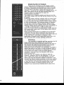
CONFIGURATION
DESCRIPTION
OF CONSOLE
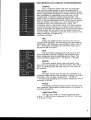
Ledbor
The 11 segmentledbar(the first led indicates
only that the powersupplyis on) is a peakreading
instrumentindicatingboth positiveand negativepeaks
which is absolutelynecessaryin modern recording.The
levelcalibrationis adjustablefrom the back of the
consolewith a multiturnpresetpotentiometer.The
ledbarreadsall signalsappearingbeforethe insertion
point of the monitor/effect
section.Thereforeall signals
that are audiblevia monitorp.f.l.This could be the
multitrackinput,the multitracksync output,the
multitrackremix,or the effect input.lt is also possible
to use the monitorsectionas an effect return without
havingto decouplethe ledbarfrom the multitrackreplay
(remix)output.Do not patchinto the effect input but
into the monitorinsertioninput with effect returns.The
ledbarcontinuesto registerthe
multitrackrecorder.
Mic
Belowthe ledbarsectionare the input circuit
controlsand switches.The first beingthe, per channel,
switchable+48V phantompowersupply.Belowthis is
the - 20 dB pad, necessaryfor extremelyhigh input
signalson the mic input.
Line
The line switchchangesthe XLR input to line
levelsensitivityand also changesthe balancedmic
inputconnectioninto an unbalancedline input.The
input sensitivityrangesfrom - 10 dBu to +20 dBu.
Remix
The remixswitch,which also activatesa line
levelinput has priolity over the line switch. The remix
input is combinedwith the sync input on the back of
the console.
Goin
The gain controlacts for the mic amplifieras a
feedbackcontroland in the line/remixmode as an input
attenuator.The mic gain rangesfrom - 20 dB to
- 64 dB whilst providingan enormousheadroomwith a
mi nim umof 40 dB.
Phose
This phasereversalswitch is active on both mic
and line/remixinputswhich proveshandy in all sorts of
recordingsituations.
HighPqssFilter
The high-passfilter is a fixed frequencyfilter
with a -3 dB turn overfrequencyat 100 Hz. The slope
is 9 dB per octave.
Equolizers
Theequalizerstandsout by virtueof its simple
yet effectivedesign,with a minimumaudiopath'a
which
guarantees
a goodsignalto noiseratio.lt is of
parametric4 banddesignwhich spansthe whole audio
spectrum.The high shelvesat 12 KHz and the low at
60 Hz.The high midrangesfrom 1 KHz to 11 KHz and
the low midrangesfrom 100Hz to 1 KHz.The lift and
cut rangeof all 4 equalizersectionsis + 16 dB. The
point of turnoverlrequenciesin this equalizerwill
pleasantlysurpriseyou. In the eventualityof still further
therefollows an insertion
equalisation
beingnecessary
point whichmakesinsertionof additionale.q. units
possible.The wholee.q.sectionis bypassablewith a
silent switch.
Aux
The4000seriesoffersin total 6 individualaux
sendswhicheasilyallowsfor the most extensiveremix
sessions.The aux sendsare per pair switchable
pre/postthe monitor/channel
fader.Basicallythe 6
sendsare wiredpre/postthe monitorfader which makes
it possibleto havefoldbackas well as effect pre and
post the multitrackmachine.
Aux fo Chqnnel
This switchconnectsall the 6 sends pre/postthe
channelfaderthis beingnecessaryin the remix mode.
Subgrouping
in the 4000consoleis done in a
Subgrouping
new way and demandsa new way of thinkingfrom the
The basicideais to havesubgroupamplifiers
engineer.
only whereyou needthem.This meansthat there is no
groupamplifierpreceeding
everymultitrackchannelas
you mighthavebeenusedto in conventionalin-line
d e signs.
In the 4000consolethereare only 4 subgroup
amplifiers,only 4? Yes,only4, but these4 subgroups
a re fullyfloating.You can switchthem to the inputsas
wel! as to the outputsanywherein the console.
l ma gine,r outingfr omchannel1 to channel28 witho ut
patching,this is possiblein the 4000seriesin the
followingway.
Thereare 4 switchesfor this novelroutingsyst€m,2 for
goingto the subgroupsand2 for comingfrom the
called"to sub" and "from sub".
subgroups,
the signalcoming from the
lf you are not subgrouping,
channelfadergoesdirectlyto the multitrackmachine.
But let's say you want to stereosubgroupchannel1 to
channel1 and 2. This meansthat you
8 to multitr ack
need2 subgroupsbecauseyou want to do it in stereo.
T h e fir stthingyou haveto do is to br ingthe signalsto
the subgroupsby pushingthe switch marked"to sub
1/2"(youare usingnow subgroup1 and 2). The pan'pot
the signallevelsent to subgroup1 andlor2,
determines
on its position,left,r ightor centr al.
d e p ending
T h e signalscomingfr om channel1 to 8 ar e now
locatedin th e
b ro ughtto subgr oup1 and 2 ( physically
. now,you needthem on m ultitrac k
ma stersection)But,
ch a nnel1 and 2. You onlyhaveto connectthe
Ei
Irrul,
rh.l
'1':
-
.h.13
I
|
.:
-;r
nuur
, wt+rtur
i-J
lrrr
iul,
l_
-
,
multit.rack
inputsto the outputsof the subgroupamps.
This is doneby switchingthe "from sub %" switches.
As you can see it is veryeasyto bring this signalto
any multitrackinput or evenmorethan 1 multitrack
channel,if you like.
For anotherexampleyou might want to bring channel,
l e t' ssay9- 10 to tr ack4. Pushin, in channel9- 10, the
"to sub Tz"switch(or "to sub 3/r"switch,which everone
pan to the right and push the switch in
is available),
channel4 called"from sub 72" (or again "from sub 3/"
if chosen).You see this is a very flexibleway of routing
a signalthroughthe console.In fact it is possibleto
route,withoutpatching,from any input to any output.
This systemallowsa greatsavingin switches
electronicsand labourwhencomparedwith the
conventional24 track routingsystem in a standardinline console.
Besidessendingthe signalto the subgroupsit is also
possibleto feed the mastersection simultaneously.
Pqn-Pot.
As alreadydescribedabove,this control (with a
-3 dB attenuationwhen set central)pans the'signal
betweenthe odd and evensubgroupsas well as
left/rightmasterbuss, if selected.
Monifor Section
The monitorsection(lightcoloured)takes care of
all the monitoringin the channel.
Sync
The sync switch in the monitorsection handles
the syncswitchingof the multitrackrecorder.In the on
position,the monitorsectionin the channelis switched
from the inputto the ouputof the multitrackmachine.
Effecl
The switch "effect" makesit possible to use the
monitorsectionsas effect returns.In this manneryou
havecontrolover as many effect returnsas the console
has channels.The effect inputsare on the back of the
oonsole.
ond Mule (Monitor)
P.F.L.
The p.f.l.switchenablesyou to prefadelistento
the signa!comingfrom the channelor from the
multitrackas well as from the effect input.The p.f.l.is
of the autotype,it switchesautomaticallythe stereo
masterfrom the monitoringand substitutesit for the
activatedchannel.
the signalcom i ng
M utingis doneby cancelling
from the channel,sync or effect inputs.The p.f.l.is not
affectedby muting.
FoderMonifor
This smallfader,58 mm travel,is of the
carbontrack
type.Thereis a 10 dB gain factor in the
amplifierwhich followsthe fader.
P.F.t.
ond Mute(ChonneD
The p.f.l.and mute switchesin the channelshave
the samefunctionsas in the monitorsections.The p.f.l.
doesnot interruptthe signalpath.The mute function
has a led to indicateits function.
Foder(ChonneD
The channel fader is of the carbonlrack type with
a 100 mm length. Standard is the Nobte fader. Options
are A.L.P.S.and Penny and Giles. There is also a 10 dB
g a i n f a c t o r i n t h e a m p l i f i e rw h i c h f o l l o w s t h e c h a n n e l
fader.
Mechqnicof Slrenglh
Themechanicalstrengthof the individual
mo dulesis achieved
by usinga speciallym anufactur ed
"U" typeprofileto whichthe printedcircuit board is
firmlysecured.
Inputs/OutpulsChqnnet
On the backof the consoleyou will find the
in/outputsof the channels.On top there is the XLR type
input connectorfor the mic and line amp.The mic amp
is bafancedand the line unbalanced.
Next there is the
combinedsync/remixinput whichacceptstwo levelsof
+4 dBu (theprofessional
standard)and the - 10 dBV
which is the semi-professional
standardnow-a-days.
MultitrackFeedis the outputof the channelwhich has
to be pluggedinto the inputof the multitrackmachine.
On this socketalso thereare +4 dBu and - 10 dBV
levelsavailable.
We haveusedthe followingwiring
configuration.
On tip of the jack the - 10 dBV signal is
hvailableand on the ring simultaneously
the + 4 dBu
standard.
By connectingto the appropriatesofdertagon the
stereojack plug you choosethe tape level you are
goingto use.The channelinsertis the jack into which
you can insertancillaryequipmentsuch as
compressors
noisegatesand otherfrequentlyused
effectdevices.The tip is the send and the ring is the
return.
The effectjack is thereas an extraline levelinput in
the remixsituation.The monitorinsertis there to make
possibleextraequalizingor the insertionof other
a n cillar yequipment
in the monitor ingsectionof the
ch a nnel.
The calibrationcontrolis thereto calibratethe levelof
the peakreadingledbar.lt is factoryadjustedto
i n d i cate6 dB downfr omthe signalwhich is actually
measured.
This way of calibratinga peak readingledbar
is commonpracticenow-a-days.
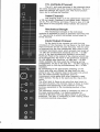
MosferSeclion
Thefollowingdescribesfrom aboveto belowthe
,se and |unctionof-themastercontro|s.First there are
tnJ ettiemelyprecise25 segmentpeak readingledbars
;iih ilth irio'iitive and nelativeieadingdisplav',The
jttici and decaycharacterlstics'conform
to standards
is the
ledbars
these
;;; iht;rgrtri the world.Below
with
parall.el
in
wired
is
which
;ffi"';;r;Eiaiion meter
indicates
instrument
precision
This
meters.
[ne ieOOar
ine exactphaseretitionsnipbetweentwo givensignals'
for
)i'in-iiJ shitt ot so; oegreesor tess is acceptable
into
green
(out
of
but-abovethis
;;;;;6paiabilitv
a....
reg-isters
;;i t C"bceptaule.The phase-meter
When
dBu'
20
+
and
bi#.t t.ioinil oetween 40 dBu
below
signal
a
with
or
witti onli one sign-ql
il;;;i.a
"- a6 Je;ii-s*ircn6r-itsetf-off,so avoidingany incorrect
reading.
produces
ffre ostiltatoris of the phaseshift type which
a low distortion1 KHz sinewave'
ilfi;; iGl*itin is lctivated a 1 KHz tone is available
dBV lev el '
mt m ultitr aikoutputsat + 4 dBu/- 10
pr
oce*r e'
sim
ple
a
fi mlfes liningup macnines
" i l"in*n
at D & R
we
sectidn'
fnii'in"ti is the iommunication
ilnOgooOcommuni.ationbetweenthe studio and of a
control room an arls-Jrui"necessityfor the success
ineiefore the 4000series offers the
;;;ili;s;"siion.
'p-*Ji6iri'i'v
communicationf rom the
oi Lomprehensive.
stages
5troio to'the contiotroom at all times and in all
the
from
speak
to
possible
6i-" J"ilion-. lt is also
by
conttof-om to the stu'diovia all outgoinglines
outputs'
meansof the aux
iwitch mar.6sit possibleto put information
Ti;|"i"
on taPe.
attenuated
e; lTJbr the talkbackswitchthe.G'R'M'is
electret..
in'
qualitv,
built
;i ifi6. inlt" it a high
purposes'A high pass f ilter
i;; talkbac''k
iii"tiinl.;
furtherincreasesthe claritY'
AuxMosfers
with theira'f'l' switches
The6 auxmasters
levelof the aux sends'
ouigoing
tot;i
controt'in-e
c.R.M.
C.R.M.standsfor ControlRoom Monitorand
control
ine reuil? airinl lignatsqgiftst9 tl9
resutateJ
switchesis foundin
e numoEioi pusn'outlon
monitor.
switch:
of ihe c.R'M'
i'nenLignoourhood
i*iicn,-tnisswitchmakesit possible
Thestereor
2 stereosourcesInsteadof the master
i6'i"rldittom"nil
mixdown.
betweenstereo
iiiii monoswitchmakescomparison
monitor
Mutecancels.the
il ;il" possible.
monitoring'
alternative
for
.otpi"t"iy. Aft.mon.stands
in
another
bring
to
switch
It-ilfi;iijle withihis
monitorsystemif oneis connected'
switches
.1..
whetherp.f.l./a.f
ril; dl.tJi.i.r.reJindicates
activated'
tne consolehavebeen
;ilil;;in
but A'L'P'S' or Penny and
Noble faders ate-s-tanOard
optionall}l.
areaveilable
Giles
MqslerSeclion In/Oufpufs
Thereare21 in/outputson the masteroutput
section.Therefollows a descriptionof these from top
- to bottom,beginningwith the left hand row as iiewed
from the rearof the desk. Firstlythere are the Aux
outputs 1 - 6. All the aux outputsare unbalancedat + 4
dBu. Then belowthe six aux jack socketsthere is a
seventh,which is a balancedmic input for
purposes.
communication
The middlerow of masteroutputs and the row on the
right whenviewedfrom the rear areas follows from top
to bottom.
Firstlythe masterleft/rightoutputswith an output level
of - 10 dBV on the tip of the stereoiack and + 4 dBu
on the ring. Next we have anothermasteroutput similar
to that just described.This secondoutput is intended
for use with a secondmastermachine.Below these
are the 2 stereoreturnsfor the master
master-outputs
machine.Thesestereojacks havean input sensitivityof
- 10 dBV on the tips and + 4 dBu on the rings.
Belowthe stereordturnsare the masterinserts and two
aux insertsand finallythe 2 C.R.M.iacks which deliver
the C.R.M.outputs.
Powersupplyconnectionis by meansof a 5 way XLR
connector.The two earth connectors(one below the
powersupplyinput socket and one in the patch bay)are
to be used whena patchbayis installedin the
mainframeto preventearth loopswhen patching. Link
the two pointswith a heavyearthing.conductor.
Pofchboy
The patchbayis modularand has provisionfor 64
break patch-pointsper module.The connections
betweenthe patch-pointsand the socket at the rear ot
the consoleare madevia two prlntedcircult boards
which haveat the back nlolex pin'connectors.
Patchingis done as follows: lt is necessaryto solder a
stereojack plug to one end of a twin screenedlead (in
which eachof the conductorsis individuallyscreened).
To the otherend soldera two pin molex female
connector.You now havethe standard4000series
internalpatchcord.
Now let's say, for instance,you want to wire the
channel1 insertionpoint to the patchbay.To do this
plug the
take a 4000seriespatch cord (Jack-Molex)
stereojack into the insertionsocketon channel 1 and
connectthe Molexfemale connectorto the pins marked
1 on the Molexstrip connectoron the rear of the desk.
In this way you can bring any in/outputjack to the
patchbayby meansof simpleexternalwiring and
furtherit is an economicalmethodwhich savestime.
A. Singlesource on singlblrqck-Recording
Themicrophoneor line signalentersthe
in/outputchannel,at the point wherethe mic/linepush
bultonwill determinethe input mode.A gain controlfor
the microphone
and line signalsis providedwith
additional- 20 dB pad for the microphonesignal.
Phasereversecan be usedon both mic and line
signals.lf necessary,
the 48 volt phantompoweringcan
be switchedon.
Firstlythe signalgoesthroughthe high-passfitter which
can be switchedin or out. After passingthroughthe
high-pass
filter it entersthe equalizersectionwhich can
also be bypassed.Afterthe e.q.the signal appearsat
the ancillaryequipmentjacksocket.This providesa
send and returnpath for the introductionof effects or
othertreatment_of
the signal.The p.f.l.switch monitors
afterthe insertionpoint,but beforethe mute switch.
Directlyafterthe mute switch(abovethe mute led) is
the long travelfader.This fadersendsthe signalvia the
channelpan-potto the master/groupbusses if
activated.
ln case of a singletrack recqrdingit is better to by-pass
the pan-potand the group-amps.
This is done simply by
not activatingany of the "to" and "from" switches.In
this way only the post faderchannelamp is directly
connectedto the multitrackinput.Thereare two ways
of monitoringthe signal,directlyfrom the channel:
- by pushingthe masterroutingswitch,which leaves
the monitorsectionfree for otherpurposes.
- the 2nd way is to use the monitorfader and its
associatedpan-potwhichfeedsthe signal directlyto
the mastermix busses,if the monitormute is not
activated.
It is an absolutenecessityto mute everyunused
monitorchannelin orderto achievebest overallsignal
to noiseratio in the mastermix busses.This muting
removesthe mix resistorsfrom the buss and thereby
providesa lowernoisegain.In an unusedchannelthe
masterswitchhas to be inactiveto achievebest signal
to noiseperformance.
Whenno effectswitch is activatedthe led bargraphwill
readthe signalgoingto the multitrack.Aux sendscan
best be usedpre/postfrom the monitorfader.In this
configuration
the aux sendsare also availablein the
sync mode.lf you wish to monitorfrom the channelyou
haveto pushthe aux to channelswitch.
The standardway to recordin one channelis to drive
the multitrackmachineas hardas possibleand to
monitorthe signalthroughthe small fader.Both in the
recordingmodeand in the sync mode.
B.Multiplesourceson one or two trocks
or line sig nal
W henmor ethan one micr ophone
has to be recordedon a singletrackor on two tracks
for stereo,a submixfacilitywill be required.
On the 4000seriesthis can be done,simply,without
patcning.
willbe
0rlinesignals
Themicroph0ne
processedas describedunderA, exceptthat one of the
two sub switchesmust be activated.lf you push,for
1?
example,routingswitch"to sub th" in channel1, the
signaiwill, dependinguponthe posltionof the channel
pan-pot,go to subgroup1 andlor2.
channelto
To bringthe outputof this subgrouped
multitrackchannel1, lt is only necessaryto activatethe
switch"from sub 72" In channel1. Now the subgrouped
signalreplacesthe channelsignal.In this way you can
routeas manychannelsto the subgroupamps as you
wish and connectthe outputto any multltrackInput in
you llke. lt ls posslbleto make 2
the consolewherever
at
the
sametlme and to brlng these
subgroups
stereo
to 4 multitrackchannels.lf moresubgroupsare required
you can use the 2 stereosubgroupsas 4 mono
subgroupsby using the pan-Pots.
Whentakingsignalfrom the subgroups,note that odd
numberedchannelsare fed by subgroupoutputs 1 and
3 and evennumberedchannelsby subgroupoutputs 2
and 4.
Sub
lmagineyou havea mix of 12 channelsin perfect
bafancerouledto track 1 + 2 and becausethe overall
signallevelis to high for the tape machineit becomes
necessary
to attenuatethe mix. This can be done as
follows.
the "from sub %" switchesin channel1 +
De-activate
2 andactivatethe same numberedswitches in two
otherunusedchannels.
Fromthese unusedchannelsyou can now patch from
the monitorinsertsends into anothertwo unused
channels.In thesetwo channelsactivate"to sub 3/"
and activatethe "from sub 3/" in channels1 + 2.
Sync
Thesync replayis done simplyby activatingthe
sync switch.The monitorfadershandlethe sync replay
signals.
C. Overdub
Whena smallpart of an allreadyrecordedtrack
severalcomplicationsarise due
has to be re-recorded,
to the fact that for monitoringand cueingpurposesthe
track has to replayedin the sync mode before and after
whilst during the re-recording
the part to be re-recorded,
the channelshouldfunctionas for normalrecording(as
describedunderA).Whenthe recordergivesthe input
signalon its outputs(if not in the sync or replaymode),
the followingsimpleset-upis preferred.
or line signalas underA, but
Processthe microphone
with the channelin the sync mode.Now the engineer
can listento the sync signalcomingfrom the machine
w h i chtellShim at whichm omenthe will go into
overduband as soon as the multitrackgoes into the
recordmodehe hearsthe musicianplayingor singing.
wouldliketo hearthe musicianalso
l f th e engineer
beforeand afterthe dubbinghe only has to push the
masterroutingswitch.
On the otherhandthe musicianhimselfhas to hearthe
sync signalas a guide as to whereto start dubbinq
- ------v and
he wantsto hearhimself beforedubbing.
The set'up for this situationis as foilor,is.use another
inputchanneland give the studio fotdbackfrom foi
instanceaux 1. The musiciannow hearshimself
(activate"aux to channel"first)via this channel's
foldbackfacilities.
BoyLgthis signalto the multitrackand place the
multitrackssync signalalso on the aux 1 buss.The
musicianwill hearhim selfcontinuously
befor e,Our i ng
and after going into the recordingmod'e.
D. Remix
Whenall trackshavebeen recordedto full
salisfaction,
the final end mix will haveto be made.All
the remixswitcheshaveto be activatedand the master
switch."Aux to channel"has to be activatedtoo. This
is a basicset up for B- 16- 24 tracks into 2. Ensure
that unusedchannelshavetheir masterswitchesin the
off positionand that the mutingswitchesin the
monitoringsectionare in the "mute" mode to optimise
signalto noise ratio.
Eachchannelmonitorsection(lightcoloured)has an
effect return.This can be used.a6an extra iriput in the
remix.Thesecan be used in combinationwith the
mic/lineinputs.A 24 channeldeskthen provides4g
inputs.
Subgrouping
il the remixis easilydone by removing
those signalsfrom the masterbusses(de--activate
t[e
"masteF"switch)which haveto be subgroupedand
routingthem to the subgroups.
In thosechannelswhereyou activatethe ',from sub"
switchesyou havea pre-mastersubfaderin the
monitoringsection.
By followingthg signalpath in the btock-diagram
the
aforementioned
situationswill becomeclearl
Servicing
Servicinga moduleis very easy. Firsily remove
all the in/outputjacks from the bact<6t the channel.
Thenunscrewthe back paneland take it out of the
consoleafter havingdisconnected
the XLR plug. Now
removethe 24 conductormolex flatcableanb tne
6 conductorflatcable.Nextstep is to unscrewthe
moduleand take it out of the mainframe.ln the master
you haveto unplugthe powerXLR plug before
sec.tion
takingout the mastermodule.
Summory
It shouldnow be apparentthat the D & R 4OO0
seriesin'tine-conp.ore?
redr'iieni a'noveI appio"cn-t-o
desig-n.
We.shorid
afso tike to Orifi! to t;;
99ls9!e
attention
the followingfacts.
Gonsoleconstructio-n
is made from steer which gives an
excellentshietdingfrom crosstarkand externlr
fi.r.r] o,.
E.M.l.(noise).
As alreadystated this 4000series is fuily modurar.
meansthal anv mainframecan accept t-OmoOui;;;iThis
47 mm width.fhe mastermodureG t*ice this
width.As
an example1 mainframecan accept:
8 in/outputmodulesanOone ni"rt",
4 in/outputmodures4 brankpJnetsand one
master
6 in/outputmodutes1 masteiinab p"i"n'pi"6i-'
m odules.'
2 mainframescan accept:
- 16in/outputmodelsi master
module.2patchpanel
modules.
3 mainframescan accept:
- 24 inrovtputmodurei 1 master
modure4 patchpanel
modules.
All modulesare fully interchangeable
in the
mainframe
to realizeany cbmbinationyou have in mind.
Oplions
Optionalextra'sare availableif desired
e.q.on/offleds
p.f.l. on/off leds
from sub on/off leds
monitormute on/off teds
l.L.P.S.professlonalcarbontrack faders
lgonl, & Gitesconductiv"pi"itic i"i"r,
Stands
- system
-'-'Y"' ,,SCORE,,
FO".l and_Mute automation
(Studio
COmputerREmix).
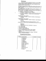
OrdedngInlormqfion
Mainframe
subframe
channels
master
blindpanel
patchpanel
patchcords int.
patch cords ext.
fadersopt.
ledse.q.
ledsp.f.l.
leds from sub.
ledsmute
stands
systemcosts
SPECIFICATIONS
Notes:Nominaloperatinglevelthroughoutthe consoleis 0 dBu (o.775 v) -
Nominaloutput levelis + 4 dBu/-10dBu.
Microphone
Preamplifier
eleclronicallybalancedR.F. suppressed.
i n p u ti m p e d a n c e
2 kOhm
gain +64 dB to +0 dB (44 dB variable
gain with 20 dB "pad"
headroommin.40 dB. Max rnput + 20 dB.
noise - 126 dB (A weighting)
lrequency responsereferred to 0 dB at 1 kHz
- 0 . 5 d B a t Z O U z O . Sd B , a l 4 0 k H z _ 3 d B a t 1 1 0 k H z
Harmonicdistorlion
with - 20 dBu input
with _ 20 dBu input
6-Jbu outpuf
+ 20 dBu output
o.ooary" ai 50 Hz
0.0086% ar 50 Hz
0.0081%al 1 kHz
0.006 % at 1 kHz
0 . 0 0 9 5 %a r 1 0 k H z
0 . 0 1 8% a t 1 0 k H z
Line/Remix
Amplilier
inputimpedance10 kOhm
gain.from-,10 dBu to intinity
headroom22 dB
Equivalenlinout 6ise
.- 96 5 dB (20-20.000 Hz)
trequencyresponsereferredlo
odBat
1 kHz
-0.5 dB at
8 Hz
- 0 . 5 d B a t 1 4 0k H z
- 3 dB at 400 kHz
Harmonicdistortion
0 dBu outpul
O.0074o/o
at 50 Hz
O.0Q24o/o
at I kHz
0 . 0 0 5 8 %a t 1 0 k H z
+ 20 dBu outout
0.0074oh al 50 Hz
0 . 0 0 1 6 %a t 1 k H z
O.O048o/o
at 10 kHz
Equalizer
Seclion
+ 16dB al 12 kHz
+ 16dB from 1 kHzlo 11kHzwilh
Q faclor 1.5
+ 16 dB from 100Hz to 1 kHz with
O factor 1.5
+16dBat60Hz
high pass 100 Hz
slope 9 dB per octave
distorlionall tiltersunitygain
0.OQ74o/o
at 50 Hz
0.00€.20/o
at 1 kHz
0.013 o/oal 10 kl-lz
all filters + 16 dB
O.O017o/o
al 50 Hz
0.008%atlkHz
0 . 0 0 1 6 %a r 1 0 k H z
Overall
Performance
sync/elfeclinput impedance10 kOhm
sync sens. +4 dBu/.10dBu. EffectsensO dBu
Oulputimpedance100 ohm on all
outpuls
max output + 22 dB into 1 kohm
and above
Record
Mode
Test-condition;
One channel,assignedto
and from groupbussoutput,
microphoneinpul loadedwilh a 150 ohm
source, mic preamp_
sel for 30 dB gain
g r o u p o u l p u +t 4 d B u
frequencyresponsereferredto 0 dB at
lkHz -0.5 dB at 20 Hz and 2O kHz
Mix
Mode
lrequency response
-0.5 dB at 17Hz
from line inputslo stereomix buss
outputs
ref lo 0 dB at 1 kHz
- 0.5 dB at 40 kHz
- 3 d B a t 1 3 5k H z
clistortion
no more than 0.009% at lkHz
headroom+22 dB, outpul arnp + tg dB
Crosstalk
Record mode
DirectAssignbelweenlwo channelsbolh
at 30 dB gain + 4 dBu outof
c h a n n e l1 , 1 5 0o h m s o u r c eo n c h a n n e2l
input.
Crosstalkon channel2 (relerredto + 4 dBu)
1 0 0H z b e t t e rt h a n - 8 8 d B
1 kHz betterthan - 90 dB
1 0 k H z b e i l e rt h a n - 7 4 d B
Mix
Mode
C h a n n e1
l i s f e d w i t h + 4 d B u ,f a d e r
al unily pannedto left. Slereomasler
fader at maximum.
Channel2 is lerminatedwith a 20 ohm
source.
Faderat unily,.panned
to righl stereo
masler.
Crosstalkon right masteroulput.
1 0 0 H z b e l t e rt h a n - 7 7 d B
1 kHz belter than - 70 dB
1 0 k H z b e l t e rt h a n - 6 3 d B
dislortion
O.O17o/oat 50 Hz
0.0094o/oat 1 kHz
O.O52o/oat 10 kHz
norse
- 84 dBu below + 4 dBu
outpul (20-20.000 Hz)
noise - 84 dB betow + 4 dBu (20-20.000 Hz)
measuredat the slereo buss outputswith
stereomasler fader at max. all channel
fadersal full attenuationpanpotsat their
cenler positions
- 83 dB below + 4 dBu (ZO-20.000 Hz)
wilh one channelfader at unity gain
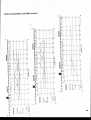
15
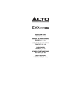
Tlpicol equolizerond filtercurves
a
Fs
.,2
o
I
lrJ
. =7
l
I
J
I t uI
!| ltEi,
t
d
o
e
ol
E
tlE
tli i i (\,J
a
1i
fl"1
r..
E;
li!9r ll
rI l
'.1
-uI
i;D l
a
<--
i i l l uon)
li:. l
fl
f il i
913
'll
o
o
o
d-
0l
ol
al
il \ ,
EI
€,1
It:#'-,
t9t
I
|
|
|
l
ll'tffiE'
|
|
|
H*ll rl rl rl
Iql
Hi
|l -rl I
l.l
lllI c.
l1i
rl
!l
ol
ol
ol
IlJ,
IH
H
t r i( , l
at
el
al
ll'
ar
1,1
f,l' ; l
tl= l
:I
H
t l:t
9r
fl! I
ll
Rr
lil3l
l,l
l''i
(J
z
^u,
6tr
9Ct
cl
fi||.1. 2; lt
ll
II
Ll
g
|!
Eir_l
,HI
E'l//\' I' l,;
,'=
,
H
Iisl
o
o
rl
l !
Fj e
l!
HI
Ei
rC
I
II
II
II
t
T
t IH
:
F
:
r3
I
Ii o
zl
I
'
I
\tr
I
I
-
-
II
i:',#;
: H=d,t T"$
: H.is; ,.:
zl
z'l
lo
i
"aro
|
.l
i
-,t-
--
z
I
. . f---a---------1=t
r 8 ul ) t
I
I
I
rP
Iti "3
_rg
ts-r
B fr,9
lit Ii p
tl
tlflI
F
ll!e
tl
l'l n
-iim,
H=:rk\ff'
Es
I
l;
dI
tlt jr l
I
J
H;lroq
EI
HT
lI
I
il2l
!effi'
F
FI
I il
H
l,'1
ii:l
o
I
I
I
tDl
!l
I
| . rI
I
I
i r .,l
U
l{l
E;l#i/U
I
I
i=l\Yil I :
I
lt, .BIEI l
OI
I
3r-
llG
AI
mHtffi€
HHFffi'
Erffi*
dl
e
!
It
I
.l
t t i3l F
I I
.i
I
itf{s
"11
T ;l
HU: F| l
tt
l:l
I I I I li
tilt I I I I il
|l El
I
n
ft
{ .-^.-----.-
o
o
o
ttl
H :.s
8
lil
x
|
l$^
t!'
E ;*s$ :i
\4
J'\'!9
\6
io
.U)
o
3c
l_-.
r
;-'
'I
H:igT
f
d
product
safety
Thlr producl lr manufacttrrd wlilr lhr hlgherl
.tendit tt and lr doublc chcclGd ln our
quallU cofrol dopartnenl for rcllablll$ In tho
'HIGH VOLTAGE'rcc0onCAUTION
. Nevet remove any panels, ot oPen lhis
equipaent No user servi:ble parts inside.
. Equipmant PoYter supply musl be grounded
at rll lines.
. Only use this product .s described, in
user nanual or brochure.
. Do not operate thb equipnent in htsh
bumldlty ot erP$e it to waler or other U'
qulls.
. Ched lbe AC powel supply cabhlo assure
secilr! contact
. Have yout eguipment cheded yearly by a
quatrLd deabr rervice center.
. Hazardous abclrlcal sbod can be avoided
by arefully folbwing tbe above rules.
EXTBA GAUTION FOR LIVE SOUND
Ground all equlpneni using the ground pin
in the AC power supply cable. Never lemove
this pin Ground loops should be eliminaled only
by use of bolation transforrnersfor dl inpu'ts
and outpub. Replace any blown fuse with tbe
same type and rating only after equipment has
been dbconnected from AC Power. If ploblern
persists, teluln eguipnent to qrdlf icd scrvicc
tachicluPlcaro cercfulV rcad the followlg lnformailon
Especially in sound eguiprnent on stage the
f llowing ,information is essential to lnow. An
electrical sbod is caused by voltage and curlenl,
actually it b lhe anrrent that causes tbe shocl.
ln practisethe higber the voltage the bigbet tbe
cunenl will be and tbe higher the shod'
But lbere b another lbing lo considerand il
is resistance.Wben tbe resislance (in Obms) is
high belween two poles, the current will be
low and vica versa.
All lhree of these; vollage, current, and resis'
effecl
tance ate important in determining tbe
of an electricalshocl,. Hcucycr, tle rcvcrily
by
dctlrnirad
i: prinerily
of e shct
llrn3l
lbvirg
crrr;ll
rl
ll:
trnrl
p:rrD.l
e
A person can feel a sboct because tbe
musctes in r body respond to electrical surtent
and because the beart b a muscle it can at'
lecl, when tbe current b btsb enough. Current
can also be fatal when it causes lhe cbest
muscleslo cpntlacl and stop breathing.
At what potential b orlrcnl dangereous.Well
the lilst leeling of qtrrent b a tingle at 0'001
Atnp of cullenl; Tbe currenl between 0.1 AmP
rnd 0,2 Anp is latal
lmagine tbat yout bome fuses of 20 AmP
can bandle 200 times mors curtent than is necas'
How does resislance affecl lhe
3ary to till
resistance between
:hoct . a psr$n feels. Atypical
'dry" clndition could
one b;nit to the otber in
rrG plryirg
well over l@,000 Ohn. ll tn
prhsapcrspirir3
it
brdy
lr sh3c t.u
lrlersd
ls
brdy
rcsirhrcl
ly ud
trrr
5OZ. TLb b t sil:etiu
llrr
by r.rc
Current
fhlcuily
cll
srrlcrl
ir ilicl 'when
tbere b r difference in ground
wilt llow
potenlial bglween equipment on stage urd in lbe
P.A. systen
Pbase do cbecf I there b any potentlal be'
lween lhe bousing ol tbe miles and tbe
guttulsynth amF, which will be linled by your
body on 3taga lmaginc, a Suitar ln youl hand
urd your [p cbse lo the nile! A ground poten'
tial dillerencr ol above l0 volts b nol unusual,
in improperly wirad buiHings it can possibly be
!s hish as 240 volts. Alltbough removlng the
ground wire sometirnescure3 a systern hum, it
will creale I Yety buardeous siluation tor the
perforning
- 'Alvry: musiian.
bY
cqrlPnalt
df
:irtl
t.rr
reir:
grirrdirg
Phgllc
Pir ir trtr
bY
bc crrcd
ulY
tbrld
lrpr
Err
irprtfrrtprt
erd islletin
pr.ptr
ririrS
lrerstrn:rt.
Replace luses always witb the same tyPe and
ratin{ after tbe eguipment has been tutned off
urd unplugged. lf the luse blows again you
bave ar eguipnent failure, do not use it again
urd relurn it to your dealer lor repair.
And hst but not least Be carefull not to
toucb a person being shoded as Vou, yourself
could also be sbocled' Once temoved lrom tbe
sbocl, have someonesend for medical help in'
nediately.
AlwaYs keeP the above
mentioned information in mind
when using electricallY
pdflered equipment-
nederlands
PAN POTDeze knop bepaald per kanaal de plaats van het
signaal in het stereo beeld. Dat is van volledig
links/rechts tot elke positie ertussen. Het signaal
wordt dus verdeeld tussen de even en oneven
subgroepen
alsmede
de
links/rechts
masteruitgangen. Wanneer de pan pot centraal
staat wordt het signaal 4,5 dB verzwakt.
M O N I T O RS E C T I E De monitor sectie is wit. Het vergemakkelijkt de
bedieninE en maakt het paneel overzichtelijker. De
volledige monitoring in een kanaal wordt door
deze sectie geregeld.
SYNCDe sync-schakelaar in de monitorsectie bepaald
het opnemen cq weergeven van de meersporen
recorder
in
de
monitorsectie.
Wanneer de
schakelaar ingedrukt is geeft dit aan, dat de
monitor sectie in het kanaal automatisch wordt
geschakeld van de ingang naar de uitgang van de
recorder.
EFFECTDe
effect-schakelaar
stelt
U
monitorsectie als effect return
Hierdoor heeft U net zoveel effect
tafel kanalen heeft.
De effect ingangen vindt U op de
de mengtafel.
in
staat
de
te gebruiken.
returns als de
achterzijde van
PFL en MUTE (monitor)
Via de pfl schakelaar luistert U v66r de fader
naar het signaal dat komt vanaf de kanaalfader of
van de meersporen recorder, alsmede de effect
ingang. Deze pfl is auto-type, dat betekent dat
de pfl automatisch de stereomaster van de monitor
afschakelt en deze vervangt door het gekozen
kanaal.
De mute toets onderbreekt het signaal, komende
van de multitrack sync of effect inputs. De pfl
wordt niet door de mute beinvloed.
F A D E R M O NI T O R In de monitor sectie is een kleine, 58 frh,
carbontrack fader gemonteerd. U heeft l0 dB
versterking ter beschikking in de versterker die
na de monitorfader volgt.
EQUALIZERSDe equalizer van de series 4000 is niet gecompliceerd maar
wel uitermate effectief.
De signaalweg is minimaal
een
uistekende
ruJs verhouding
waardoor
signial
verkregen wordt. De viervoudige equalizer omvat het hele
audiospectrum.
De
laag cq
hoogsectie heeft
zijn
kantelpunten op resp. 60 Hz en 12 kHz. De high-mid
toonregeling loopt van I tot l0 kHz terwijl de low-mid een
bereik heeft van 100 Hz tot I kHz. De kantelpunten ziin
zeer muzikaal ontworpen; ze zullen U verrassen!
Mocht extra toonregeling nodig zijn: een insertie punt is
gemonteerd direct
na de toonregelsectie. De gehele
toonregeling
op
een
kanaal
kah
d.m.v.
een
bypass-schakelaar overbrugd worden. Een led geeft aan
of zij al dan niet is ingeschakeld.
AUXDe series 4000 heeft in totaal 6 effectsends te bieden
wetke ruim genoeg zijn voor de meest uitgebreide
remixsessies. Ze ziin per paar pre/post de monitor fader
schakelbaar. Wanner de aux-to-channel wordt ingedrukt
zijn de effectsends pre-post de kanaalfader schakelbaar.
Staat deze schakelaar niet ingedrukt dan is het mogelijk
pre/post de monitorfader een signaal aan de muzikanten in
de studio aan te bieden. (=foldback) Mede is het mogelijk
een effectapparaat aan te sturen voor of na het signaal
van de multitrack recorder.
AUX-TO-CHANNELDeze schakeling zorgt erv(x)r dat alle aux sends pre/post
de kanaalfader schakelbaar ziin, iets wat tijdens de
remix-sessie noodzakelijk is.
SUBGROUPINGHet maken van subgroeperl in de series 4000 gebeurt op
een vrij onorthodoxe manier en verlangt een andere
manier van denken van de technicus. Het basisidee is om
all66n daar subgroepen te hebben waar men ze ook nodig
heeft. Dit betekent dat het mogelijk is op ieder gewenst
kanaal een subgroep te vormen. DeR noemt dit FSS;
Floating Subgroup System! Se series 4000 heeft 4
versterkers.
Dat is voldoende omdat de
subgroep
subgroepen dus overal inzetbaar zijn.
U kunt de
subgroepen naar de ingangen maar ook naar de uitgangen
overal in het mengpaneel schakelen. De routing van het
kanaal wordt verder beschreven onder het hoofdstuk I
Meerdere Signalen op een of twee Sporenr. Dit zwevendd
subgroep systeem bespaart erg veel schakelaars en andere
componenten vergeleken met andere in-line mengtafels. De
bedrijfszekerheid wordt hierdoor allen maar vergroot.
Uiteraard is het mogelijk om naast de subgroepen de
mastersectie gelijktijdig aan te sturen.
B E S C H R I J V I N GV A N D E B E D I E N I N G S O R G A N E: N
LED BARDe 11 segments led bar (de onderste led geeft aan of
de tafel is ingeschakeld) is een peak led bar die
zowel positieve als negatieve peaken aangeeft; iets
wat
absoluut
noodzakelijk
is
in
moderne
studiotechnieken. De level calibratie is instelbaar aan
de achterzijde van het kanaal. De led bar geeft de
niveaus van alle signalen weer welke vddr het
insertiepunt
van
de
monitorsectie
de
tafel
binnenkomen. Dat zijn dus alle signalen die U kunt
beluisteren via de monitor pfl. Dit kunnen zijn: de
multitrack input,
de multitrack-sync output, de
multitrack remix of de effect-input.
Het is ook
mogelijk
monitor
de
sectie als effectinput
te
gebruiken zonder dat de led bar wordt losgekoppeld
van het recordersignaal. Patch in dat geval niet in
de effectinput maar in de monitor insertie jack. Het
blijft dan mogelijk het niveau van het recordersignaal
af te lezen.
MtcOnder de led bar vindt U de bedieningsorganen van
de microfoon ingang. De bovenste schakelaar geeft
de mogelijkheid de 48 V phantoomvoeding per kanaal
aan/uit te schakelen. Hieronder bevindt zich de -20
dB schakeling welke gebruikt
kan worden om
oversturing van het microfoonkanaal te voorkomen.
LINE_
De line schakelaar schakelt de micrtofooningang om
naar line-gevoeligheid en impedantie. (resp. -10
6gu/+20 dBu, 10 kOhm)
REMI XIn feite is de remix-schakelaar niets anders dan een
line-schakelaar met een prioriteit boven de normale
line ingang. De remix input is gecombineerd met de
sync-input op de achterzijde van het paneel.
G A IN De gain regelaar regelt de mate van versterking of
verzwakking
van
het
aangeboden signaal.
De
microfoongevoeligheid reikt van -20 dB tot -64 dB,
met een uitsturingsmarge van meer dan 40 dB.
PHASEDe phase omkeerschakelaar werkt
microfoon- als de op de line-input.
zowel op
de
HIGH PASS FILTERHet laag df filter heeft een vaste frequentie die ligt
op 100 Hz. De afval van het filter is 9 dB per
octaaf. Ongewenst laag kan op deze manier effectief
worden weggefilterd.
Wii danken U hartelijk voor Uw keuze en het vertrouwen dat U in ons
produkt
stelt.
De DgR series 4000 mengtafel is ontworpen door en voor
professionele gebruikers.
Het geeft U een uniek in-line consept in handen
met een enorme flexibiliteit. Onze reeds twaalf jaar lange ervaring in het
ontwikkelen
en
produceren
van
geluidsmengtafels resulteerde
in
een
betrouwbare en bedrijfszekere mengtafel. Lees de gebruiksaanwijzing eerst
aandachtig door om het volle profijt
uit Uw mengtafel te halen. Schroom
niet om de aangewezen mogelijkheden te gebruiken; de megtafel is er voor
ontworpen!
Een beknopte lijst van de 4000 features:
- 1l segment led-bar per kanaal
- 48 V phantoom, p€F kanaal aan/uit schakelbaar
- phase reverse voor zowel mic- als line ingang per kanaal
- extreem ruisarme mikrofoonvoorversterkers
- gecombineerde sync- remix inputs op +4 dBu/-10 dBV
- 100 Hz high pass filter
- 4 bands sweep equalizer
- 5 aux sends pre/post fader schakelbaar
- floating subgroups
- sync- en effectinputs per kanaal waardoor een dubbel aantal kanalen
gemixed kan worden.
- monitor mute en p.f.l.
- kanaal mute en p.f.l.
- 100 mm kanaal fader, 60 mm monitor fader
- 2 inserts per kanaal
- multitrack outputs op +4 dBu of -10 dBV
- master sectie met 25 segments led-bar en phasemeter
- 1 kHz line up toongenerator
- talkback met ingebouwde electret-mikrofoon
- communicatie systeem
- 6 master aux sends met afl afluistering
- uitgebreide monitor sectie: twee paar monitors schakelbaar, mono en mute
schakelaars.
- twee stereo master recorders kunnen worden afgeluisterd
(+4/-10
mogelijk)- 54 jacks modulair patchpanel
- alle connectors via xlr of stereo steek (5,3 mm)