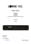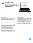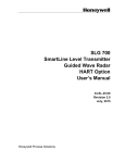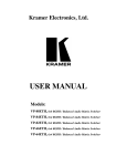
1
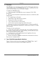
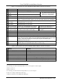
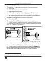
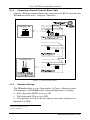
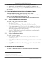
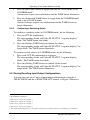
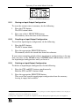
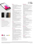
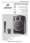
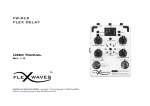
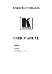
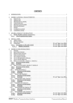
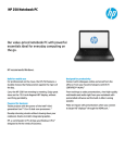
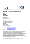
Kramer Electronics, Ltd.
USER MANUAL
Model:
VP-4x4
4x4 VGA/XGA Audio Matrix Switcher
Contents
Contents
1
2
3
4
4.1
Introduction
Getting Started
Overview
Your VGA/XGA Audio Matrix Switcher
Connecting the VP-4x4
1
1
2
2
5
4.1.1
4.1.2
4.1.3
Connecting a PC
Connecting a Phoenix Terminal Block Cable
Dipswitch Settings
5
6
6
5
5.1
5.2
Operating Your Audio Matrix Switcher
Displaying Unit Characteristics
Choosing the Audio-Follow-Video or Breakaway Option
7
7
8
5.2.1
5.2.2
Setting the Audio-Follow-Video Option
Setting the Breakaway Option
8
8
5.3
5.4
Switching OUT-IN Combinations
Confirming Settings
8
9
5.4.1
5.4.2
Toggling between the AT ONCE and CONFIRM Modes
Confirming a Switching Action
9
10
5.5
Storing/Recalling Input/Output Configurations
10
5.5.1
5.5.2
5.5.3
Storing an Input/Output Configuration
Recalling an Input/Output Configuration
Deleting an Input/Output Configuration
11
11
11
5.6
6
Locking the Front Panel
Technical Specifications
12
12
Figures
Figure 1: VP-4x4 VGA/XGA Audio Matrix Switcher
Figure 2: Connecting a PC without using a Null-modem Adapter
Figure 3: VP-4x4 Connections
Figure 4: VP-4x4 Unit Characteristics
Figure 5: SELECTOR Buttons
3
5
6
7
11
Tables
Table 1: Front Panel VP-4x4 VGA/XGA Audio Matrix Switcher Features
Table 2: Rear Panel VP-4x4 VGA/XGA Audio Matrix Switcher Features
Table 3: Rear Panel Dipswitches
Table 4: Technical Specifications of the VP-4x4 VGA/XGA Audio Matrix Switcher
4
4
7
12
i
Introduction
1
Introduction
Dedication by Kramer Electronics since 1981, to the development and
manufacture of high quality video/audio equipment, makes the Kramer line
an integral part of the finest production and presentation facilities in the
world. In recent years, Kramer has redesigned and upgraded most of the line,
making the best even better!
The Kramer line of professional video/audio electronics is one of the most
versatile and complete available, and is a true leader in terms of quality,
workmanship, price/performance ratio and innovation. In addition to our high
quality industrial and broadcast switchers and matrix switchers, we also offer
excellent amplifiers, remote controllers, processors, interfaces and computerrelated products. Congratulations on purchasing your Kramer VP-4x4
VGA/XGA Audio Matrix Switcher.
This product is ideal for the following typical applications:
Professional display systems requiring true 4x4 matrix operation
Multimedia and presentation source and acceptor selection
Remote monitoring of computer activity in schools and businesses
Rental/staging applications
The package includes the following items:
VP-4x4 VGA/XGA Audio Matrix Switcher
Power cord
Windows 95/98/NT TM Kramer control software
Null-modem adapter
This user manual
Kramer concise product catalog/CD
2
Getting Started
We recommend that you:
Unpack the equipment carefully and save the original box and packaging
materials for possible future shipment
Review the contents of this user manual
1
Overview
3
Overview
The VP-4x4 is a true 4x4 matrix switcher for VGA / XGA signals and stereo
balanced audio signals. The VP-4x4 enables the user to simultaneously route
any or all of the 4 inputs to any or all of the 4 outputs.
In addition the VP-4x4 includes:
Video bandwidth of 440 MHz that ensures transparent VGA / XGA
performance
Easy-to-connect detachable terminal block connectors on which the audio
signals reside
DC coupled inputs and outputs
Audio-follow-video and breakaway options
Storing and recalling setup options
“Take” button for precise switch control
“Lock” button to prevent tampering with the front panel
The ability to control via the front panel buttons, or remotely by RS-485
or RS-232 serial commands transmitted by a touch screen system, PC, or other
serial controller
To achieve the best performance:
Connect only good quality connection cables, thus avoiding interference,
deterioration in signal quality due to poor matching, and elevated noise levels
(often associated with low quality cables)
Avoid interference from neighboring electrical appliances that may
adversely influence signal quality
Position your Kramer VP-4x4 in a location free from moisture and away
from excessive sunlight and dust
4
Your VGA/XGA Audio Matrix Switcher
Figure 1 illustrates the front and rear panels of the VP-4x4. Tables 1 and 2
define the front and rear panels of the VP-4x4, respectively.
2
KRAMER ELECTRONICS, LTD.
Figure 1: VP-4x4 VGA/XGA Audio Matrix Switcher
Your VGA/XGA Audio Matrix Switcher
3
Your VGA/XGA Audio Matrix Switcher
Table 1: Front Panel VP-4x4 VGA/XGA Audio Matrix Switcher Features
#
1
2
3
Feature
Power Switch
SELECTOR IN
Buttons
SELECTOR OUT
Buttons
ALL Button
OFF Button
Function
Illuminated switch supplying power to the unit
Select the input to switch to the output
Select the output to which the input is switched
}
The SELECTOR IN and OUT
buttons also store/recall the
1
input/output configurations
Pressing ALL before pressing an INPUT button, connects that input to all outputs2
Pressing OFF after pressing an OUTPUT button disconnects that output from the
inputs. To disconnect all the outputs, press the ALL button and then the OFF button
6 Video STATUS
Identifies a cross point between each video output to which the video input
OUT labels
displayed below it is connected
7 Audio STATUS
Identifies a cross point between each audio output to which the audio input
OUT labels
displayed below it is connected
8 Audio IN STATUS Displays the selected audio input switched
Also displays the firmware version
3
7-segment Display to the output (marked above each input)
number and the MACHINE #
9 Video IN STATUS Displays the selected video input switched to Also displays the number of IN and
4
7-segment Display the output (marked above each input)
OUT ports
10 VID Button
Affects video (the default)
11 AFV Button
Affects audio-follow-video
12 AUD Button
Affects audio
13 STO Button
Pressing STO (STORE) followed by an output button stores the current setting5
14 RCL Button
Pressing the RCL (RECALL) button and the corresponding OUTPUT key recalls a
setup. The stored status blinks. Pressing a different OUTPUT button lets you view6
another setup. After making your choice, pressing the RCL button again
implements the new status
15 TAKE Button
Pressing TAKE toggles the mode between the CONFIRM mode7 and the AT
ONCE mode (user confirmation per action is unnecessary)
16 LOCK Button
Disengages the front panel switches
4
5
Table 2: Rear Panel VP-4x4 VGA/XGA Audio Matrix Switcher Features
#
Feature
Function
1
2
3
4
5
6
7
8
Audio INPUTS Phoenix Connectors
Audio OUTPUTS Phoenix Connectors
RS-485 Connector
RS-232 Connector
MACHINE #
Power Connector with Fuse
VGA/XGA Video OUTPUTS
VGA/XGA Video INPUTS
Audio inputs
Audio outputs
RS-485 Phoenix detachable terminal block port
DB 9F connector connects to PC or Remote Controller
Dipswitches setup
AC connector enabling power supply to the unit
Connects to the VGA/XGA video outputs (1 to 4)
Connects to the VGA/XGA video inputs (1 to 4)
1 Refer to section 5.5
2 For example, press ALL and then Input button # 2 to connect input # 2 to all the outputs
3 Refer to section 5.1
4 Refer to section 5.1
5 For example, press STO and then the Output button # 3 to store in Setup # 3
6 Only view, nothing is implemented at this stage
7 When in Confirm mode, the TAKE button illuminates
4
KRAMER ELECTRONICS, LTD.
Your VGA/XGA Audio Matrix Switcher
4.1 Connecting the VP-4x4
To connect the VP-4x4, connect the following1 to the rear panel ports:
Power cord
VGA / XGA video input and output cables
Audio input and output cables
A PC via the null-modem adapter (when using the Kramer Control
software or other controller) if control via RS-232 is required
RS-485 Phoenix terminal block cable if control via RS-485 is required
In addition, set the dipswitches as section 4.1.3 describes.
4.1.1
Connecting a PC
To connect a PC to the VP-4x4, without using a Null-modem adapter:
Connect the RS-232 DB9 port on your PC to the RS-232 DB9 rear panel
port on the Master VP-4x4 unit, as Figure 2 illustrates (depending on whether
the PC has a 9-pin or 25-pin connector)
Figure 2: Connecting a PC without using a Null-modem Adapter
To connect a PC to the VP-4x4, using a Null-modem adapter:
Connect the RS-232 DB9 rear panel port on the Master VP-4x4 unit to
the Null-modem adapter and connect the Null-modem adapter with a 9 wire
flat cable to the RS-232 DB9 port on your PC, as Figure 3 illustrates
1 Switch OFF the power on each device before connecting it to your VP-4x4. After connecting your VP-4x4, switch on its
power and then switch on the power on each device
5
Your VGA/XGA Audio Matrix Switcher
4.1.2
Connecting a Phoenix Terminal Block Cable
Connect a Phoenix terminal block cable connector to the RS-485 port on each
VP-4x4 unit in the series1, as Figure 3 illustrates.
Figure 3: VP-4x4 Connections
4.1.3
Dipswitch Settings
The VP-4x4 includes a set of 4 dipswitches, as Figure 3 illustrates above.
You configure each VP-4x4 unit by setting the dipswitches as follows:
Pull a dipswitch DOWN to set it to ON
Pull a dipswitch UP to set it to OFF
Set dipswitch 4 to ON for the first and last units only2 (otherwise set
dipswitch 4 to OFF)
1 You can connect up to 8 units
2 Acts as a terminator
6
KRAMER ELECTRONICS, LTD.
Operating Your Audio Matrix Switcher
Set dipswitches 1, 2 and 3 according to Table 3:
Table 3: Rear Panel Dipswitches
Dipswitch Settings
Machine #
Dipswitch
3
2
1
0
1
0
0
0
0
OFF OFF OFF
2
0
0
0
1
OFF OFF ON
3
0
0
1
0
OFF ON
OFF
4
0
0
1
1
OFF ON
ON
5
0
1
0
0
ON
OFF OFF
6
0
1
0
1
ON
OFF ON
7
0
1
1
0
ON
ON
OFF
8
0
1
1
1
ON
ON
ON
1
5
Self Address
Master
2
3
Operating Your Audio Matrix Switcher
Operate your VP-4x4 via:
The front panel buttons
RS-232 serial commands transmitted by a touch screen system, PC1, or
other serial controller
5.1 Displaying Unit Characteristics
Clarify the following VP-4x4 unit characteristics, as Figure 4 illustrates:
The number of IN and OUT ports2
The firmware version number and the MACHINE #3
Figure 4: VP-4x4 Unit Characteristics
1 For instructions on using the Windows 95/98/NT
TM
Control Software, refer to the separate user manual (included on the
CD-ROM in .pdf format), Kramer Control Software
2 Via the Video IN STATUS 7-segment display as item 9 in Figure 1 illustrates
3 Via the Audio IN STATUS 7-segment display as item 8 in Figure 1 illustrates
7
Operating Your Audio Matrix Switcher
VP-4x4 unit characteristics display in the following circumstances:
Immediately (and automatically) after switching on the power; and
When simultaneously pressing the 3 SELECTOR IN buttons1 1, 2 and 3,
for 3 seconds
5.2 Choosing the Audio-Follow-Video or Breakaway Option
You can switch stereo audio signals in one of 2 ways, either:
Audio-follow-video (AFV), in which all operations and status indicators
relate to both the video and the audio channels2; or
Breakaway, in which video and audio channels switch independently
5.2.1
Setting the Audio-Follow-Video Option
To set the Audio-follow-video (AFV) option:
1.
Press the AFV button.
The AFV button illuminates. The audio will follow the video.
2.
If the audio configuration differs from the video configuration, both the
Audio IN STATUS 7-segment displays and the AUD button will blink3,
and require reconfiguring for AFV operation.
3.
Press the TAKE button to confirm the modification (reconfiguring the
audio according to the video).
5.2.2
Setting the Breakaway Option
To set the Breakaway option:
1.
Press either the AUD (for audio control only) or the VID (for video
control only) button.
2.
If the AUD button illuminates all switching operations relate to the Audio
section.
3.
If the VID button illuminates all switching operations relate to the Video
section.
5.3 Switching OUT-IN Combinations
To switch a video/audio input to a video/audio output, do the following:
1 Item 2 in Figure 1
2 Audio and video connections are the same
3 Warning that changes are about to occur in the audio section
8
KRAMER ELECTRONICS, LTD.
Operating Your Audio Matrix Switcher
1.
Press an OUT button1.
The corresponding Audio and2/or Video IN STATUS 7-segment displays3
blink.
2.
Press an IN button4.
The selected input switches to the selected output.
For example, press the ALL button and then IN button # 2 to connect input #
2 to all the outputs
5.4 Confirming Settings
Choose to work in the AT ONCE or the CONFIRM mode.
In the AT ONCE mode:
You save time
Actions require no user confirmation
Execution is immediate
No protection is offered against changing an action in error
In the CONFIRM mode:
You have an optional method to help avoid making a mistake
Every action requires user confirmation
Execution is delayed5 until the user confirms the action
Protection is offered to prevent erroneous switching
You can key-in several actions and then confirm them by pressing the
TAKE button once, to simultaneously switch all monitors
Pressing an OUT-IN combination when your VP-4x4 operates in the AT
ONCE mode implements the switch immediately. When the VP-4x4 operates
in the CONFIRM mode, press the blinking TAKE button to authorize the
switch.
5.4.1
Toggling between the AT ONCE and CONFIRM Modes
To toggle between the AT ONCE and CONFIRM modes, do the following:
1 Either 1, 2, 3, 4 or ALL
2 When the audio-follow-video option is active (refer to section 5.2)
3 Items 8 and 9, respectively, in Figure 1
4 Either 1, 2, 3, 4 or OFF
5 Failure to press the TAKE button within one minute (the Timeout) will abort the action
9
Operating Your Audio Matrix Switcher
1.
Press the dim TAKE button to toggle from the AT ONCE mode1 to the
CONFIRM mode2.
Actions now require user confirmation and the TAKE button illuminates.
2.
Press the illuminated TAKE button to toggle from the CONFIRM mode
back to the AT ONCE mode.
Actions no longer require user confirmation and the TAKE button no
longer illuminates.
5.4.2
Confirming a Switching Action
To confirm a switching action (in CONFIRM mode), do the following:
1.
Press an OUT-IN combination.
The corresponding Audio and Video IN STATUS 7-segment displays3
blink. The TAKE button also blinks.
2.
Press the blinking TAKE button to confirm the action.
The corresponding Audio and Video IN STATUS 7-segment displays4 no
longer blink. The TAKE button illuminates.
To confirm several actions (in CONFIRM mode), do the following:
1.
Press each OUT-IN combination in sequence.
The corresponding Audio and Video IN STATUS 7-segment display5
blinks. The TAKE button also blinks.
2.
Press the blinking TAKE button to confirm all the actions.
The corresponding Audio and Video IN STATUS 7-segment displays6 no
longer blink. The TAKE button illuminates.
5.5 Storing/Recalling Input/Output Configurations
You can store and recall7 up to 8 input/output configurations using the 4
SELECTOR IN and the 4 SELECTOR OUT buttons, as Figure 5 illustrates:
1 The TAKE button is dim
2 The TAKE button illuminates
3 Items 8 and 9, respectively, in Figure 1
4 Items 8 and 9, respectively, in Figure 1
5 Items 8 and 9, respectively, in Figure 1
6 Items 8 and 9, respectively, in Figure 1
7 The 8 input/output configurations (or setups) also include the relevant audio-follow-video / breakaway option definition
10
KRAMER ELECTRONICS, LTD.
Operating Your Audio Matrix Switcher
Figure 5: SELECTOR Buttons1
5.5.1
Storing an Input/Output Configuration
To store the current status in memory, do the following:
1.
Press the STO button.
The STO button blinks.
2.
Press one of the 8 SELECTOR buttons.
The memory stores the data at that reference.
5.5.2
Recalling an Input/Output Configuration
To recall an input/output configuration, do the following:
1.
Press the RCL button.
The RCL button blinks.
2.
Press the appropriate SELECTOR button.
The memory recalls the stored data from that reference.
If you cannot remember which of the 8 input/output configurations is the one
that you want, set the VP-4x4 to the CONFIRM mode and manually scan all
the input/output configurations until you locate it.
5.5.3
Deleting an Input/Output Configuration
To delete an input/output configuration, do the following:
1.
Press the STO and RCL buttons simultaneously.
Both the STO and RCL buttons blink.
2.
Press the appropriate SELECTOR button.
This erases that specific input/output configuration from the memory,
leaving it empty and available2.
1 The gray numbers (1 to 8) in Figure 5 that illustrate the corresponding store/recall configuration number, are for the purpose
of illustration only and do not actually appear on the buttons
2 Storing a new configuration over a previous configuration (without deleting it first) replaces the previous configuration
11
Technical Specifications
5.6 Locking the Front Panel
To prevent changing the settings accidentally or tampering with the front
panel, lock your VP-4x4. Unlocking releases the protection mechanism.
To lock the VP-4x4:
Press the LOCK button for more than 2 seconds
The LOCK button illuminates, freezing the front panel controls. Pressing a
button will have no effect, except to cause the LOCK button to blink1.
Nevertheless, even though the front panel is locked you can still operate your
PC control software
To unlock the VP-4x4:
Press the illuminating LOCK button for more than 2 seconds
The VP-4x4 unlocks and the LOCK button no longer illuminates
6
Technical Specifications
Table 4 includes the technical specifications:
Table 4: Technical Specifications of the VP-4x4 VGA/XGA Audio Matrix Switcher
INPUTS:
4 analog red, green, blue signals - 0.7 Vpp / 75 ; H & V syncs, TTL level on
HD15F connectors
4 balanced audio stereo signals, + 4dBm / 33k typical, 21 Vpp max. on
detachable terminal blocks
OUTPUTS:
4 analog red, green, blue signals - 0.7 Vpp / 75 ; H & V syncs, TTL level on
HD15F connectors
4 balanced audio stereo signals, + 4dBm / 50 typical, 21 Vpp max. on
detachable terminal blocks
440 MHz -3dB
-55 dB
73 dB
0.05%
0.13 Deg.
<0.05%
100 kHz -3dB
77 dB unweighted
0.031%
0.02%
17 selector switches; RS-232, RS-485
19-inch (W), 7-inch (D) 1U (H) rack-mountable
230 VAC, 50/60 Hz, (115VAC, U.S.A.) 12VA max
2.7 kg (6 lbs.) approx
VIDEO BANDWIDTH:
VIDEO CROSSTALK:
VIDEO S/N RATIO:
DIFF. GAIN:
DIFF. PHASE:
K-FACTOR:
AUDIO BANDWIDTH:
AUDIO S/N RATIO:
AUDIO THD + NOISE:
2ND HARMONIC:
CONTROL:
DIMENSIONS:
POWER SOURCE:
WEIGHT:
ACCESSORIES:
Power cord, Null modem adapter, Windows 95/98/NT TM Kramer control
software
1 Warning that you need to unlock to regain control via the front panel
12
KRAMER ELECTRONICS, LTD.
LIMITED WARRANTY
Kramer Electronics (hereafter Kramer) warrants this product free from defects in material and workmanship under the
following terms.
HOW LONG IS THE WARRANTY
Labor and parts are warranted for three years from the date of the first customer purchase.
WHO IS PROTECTED?
Only the first purchase customer may enforce this warranty.
WHAT IS COVERED AND WHAT IS NOT COVERED
Except as below, this warranty covers all defects in material or workmanship in this product. The following are not covered
by the warranty:
1.
2.
3.
Any product which is not distributed by Kramer, or which is not purchased from an authorized Kramer dealer. If you are
uncertain as to whether a dealer is authorized, please contact Kramer at one of the agents listed in the web site
www.kramerelectronics.com.
Any product, on which the serial number has been defaced, modified or removed.
Damage, deterioration or malfunction resulting from:
i)
Accident, misuse, abuse, neglect, fire, water, lightning or other acts of nature
ii)
Product modification, or failure to follow instructions supplied with the product
iii)
Repair or attempted repair by anyone not authorized by Kramer
iv)
Any shipment of the product (claims must be presented to the carrier)
v)
Removal or installation of the product
vi)
Any other cause, which does not relate to a product defect
vii)
Cartons, equipment enclosures, cables or accessories used in conjunction with the product
WHAT WE WILL PAY FOR AND WHAT WE WILL NOT PAY FOR
We will pay labor and material expenses for covered items. We will not pay for the following:
1.
2.
3.
Removal or installations charges.
Costs of initial technical adjustments (set-up), including adjustment of user controls or programming. These costs are the
responsibility of the Kramer dealer from whom the product was purchased.
Shipping charges.
HOW YOU CAN GET WARRANTY SERVICE
1.
2.
3.
To obtain service on you product, you must take or ship it prepaid to any authorized Kramer service center.
Whenever warranty service is required, the original dated invoice (or a copy) must be presented as proof of warranty coverage,
and should be included in any shipment of the product. Please also include in any mailing a contact name, company, address, and
a description of the problem(s).
For the name of the nearest Kramer authorized service center, consult your authorized dealer.
LIMITATION OF IMPLIED WARRANTIES
All implied warranties, including warranties of merchantability and fitness for a particular purpose, are limited in duration to
the length of this warranty.
EXCLUSION OF DAMAGES
The liability of Kramer for any effective products is limited to the repair or replacement of the product at our option. Kramer
shall not be liable for:
1.
2.
Damage to other property caused by defects in this product, damages based upon inconvenience, loss of use of the product, loss
of time, commercial loss; or:
Any other damages, whether incidental, consequential or otherwise. Some countries may not allow limitations on how long an
implied warranty lasts and/or do not allow the exclusion or limitation of incidental or consequential damages, so the above
limitations and exclusions may not apply to you.
This warranty gives you specific legal rights, and you may also have other rights, which vary from place to place.
NOTE: All products returned to Kramer for service must have prior approval. This may be obtained from your dealer.
This equipment has been tested to determine compliance with the requirements of:
EN-50081:
"Electromagnetic compatibility (EMC);
generic emission standard.
Part 1: Residential, commercial and light industry"
EN-50082:
"Electromagnetic compatibility (EMC) generic immunity standard.
Part 1: Residential, commercial and light industry environment".
CFR-47:
FCC Rules and Regulations:
Part 15: “Radio frequency devices
Subpart B – Unintentional radiators”
CAUTION!
Servicing the machines can only be done by an authorized Kramer technician. Any user who makes changes or modifications to
the unit without the expressed approval of the manufacturer will void user authority to operate the equipment.
Use the supplied DC power supply to feed power to the machine.
Please use recommended interconnection cables to connect the machine to other components.
13
For the latest information on our products and a list of Kramer
distributors, visit our Web site: www.kramerelectronics.com.
Updates to this user manual may be found at
http://www.kramerelectronics.com/manuals.html.
We welcome your questions, comments and feedback.
Kramer Electronics, Ltd.
Web site: www.kramerelectronics.com
E-mail: [email protected]
P/N: 2900-002013 REV 2