1
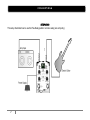
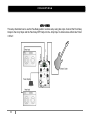
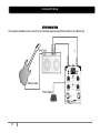
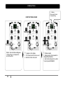
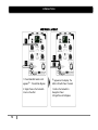
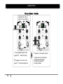
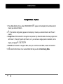
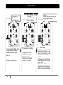
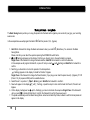
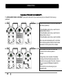
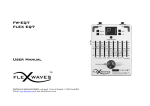
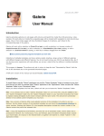
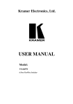
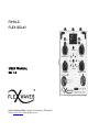
FW-DLC FLEX DELAY User Manual Rev 1.3 FlexWaves di Alessandro Belletti - sede legale Vicolo dei Rampini 13, 40026 Imola(BO) Website: www.flexwaves.com E-mail: [email protected] INTRODUCTION Thank you, and congratulations on your choice of the FWDLC FLEX DELAY Programmable Digital Delay Pedal. Before using this effect, carefully read the section entitled: “IMPORTANT NOTES”. These sections provide important information concerning the proper operation of the pedal. Additionally, in order to feel assured that you have gained a good grasp of every feature provided by your new unit, this manual should be read in its entirety. The manual should be saved and kept on hand as a convenient reference. Flex Delay is a digital delay pedal with pro studio quality: 192 KHz Sample Rate and 24 Bit Resolution. It brings you very analog, natural sound and warm tube sounding without adding the artifacts typical of DSP and the option to STORE up to 8 PRESETS, ORGANIZE them in BANKS and RECALLING on the fly. Up to 2800 ms delay time can be set with Delay knob or using your most important asset: your foot to Tap the Tempo on Tap button. Three different types of modulation can be applied to the delay repetitions and other features include Reverse, Chorus and 11 seconds LOOPER. 2 FLEX WAVES Guitar Pedals are DESIGNED and MADE in Italy. A power supply is provided with the unit. Use the power supply provided in the product box or a power supply with similar specifications. MAIN FEATURES 192 KHz (Sample Rate), 24 Bit Achieves delay times of up to 2800 ms 8 Custom Presets 6 Banks Modulated Delay Chorus 11 Seconds Looper Reverse Delay True Bypass Compact Die Cast Aluminium Box FW Balanced Cable Link Mode to “smart” connect multiple Flex Waves pedals PANEL DESCRIPTION Connections 1- IN 1/4” mono jack connections for signal input. Flex-Delay require 1/4” stereo jack connections for Link Mode operations. 2- OUT 1/4” mono jack connections for signal output. Flex-Delay require 1/4” stereo jack connections for Link Mode operations. 3- DRY 1/4” mono jack connections for dry (uneffected)signal output. 4- Power The Flex-Delay require 12V DC 300 mA. Use thepower supply provided in the product box. Important Note: FW-DLC Flex Delay input stage is set up to work with signals coming from guitar pickups, but it can happens that you have to connect the pedal to keyboards or before signal boosters like equalizer, distortion or booster effects. If the signal coming out from the effect is distorted, it means that the input stage has saturated and will appear frequently on the display. If it happens be sure to lower the output level of any devices being connected or place the Flex Delay BEFORE signal booster units. 3 PANEL DESCRIPTION Switches 5 - On/Bypass 12- Sel This footswitch has three functions. - Press and release immediately for standard on/off function in Free Set Mode (Manual). - Hold and release to switch between the presets in Preset Mode. - Hold to store a sound into a Preset number (Preset Mode) or to confirm the bank selection/bank position (Bank Mode). Press the “Sel” selection switch to select Subdivision, Modulation Type, Chorus, Reverse or Looper function. When the pedal works as a Looper (Loop Mode), hold the footswitch to delete the recorded loop. q ie3 s Subdivision The subdivision options relate to the tapped tempo.Tap the tempo in quarter notes and then select the subdivision of your choice. Quarter note - Delay repeats play quarter notes according to the tapped tempo. E.g. tap quarter notes at tempo 120 BPM. The delay time of the repeats is now 120 BPM or 500 ms. Dotted eight note – A subdivision type often used when the delay repeats add to the actual guitar rhythm. Try playing quarter notes with the delay level set relatively high. Eight note triplets - Excellent for fifties style rhythm in 6/8 where you play only on the fourth beat Sixteen note A subdivision type often used for fast tempos, excellent for country or heavy metal. 6 - Tap Tempo / Loop You can easily set the delay time to match the tempo of the song being played by pressing the pedal in time with the song‟s tempo, this can be done in both “off” and “on” mode. The subdivision options relate to the tapped tempo. Tap the tempo in quarter notes and then select the subdivision of your choice. When the pedal works as a Looper (Loop Mode), press the footswitch to start the recording and press again to stop it. 4 q i e3 s- PANEL DESCRIPTION Chorus: The Chorus function transform the Flex Delay effect in a chorus pedal. Adjust the rate of the effect using the Modul./Rate knob, adjust the depth of the chorus using the Delay/Depth knob. The Level knob adjusts the volume of the processed sound and the Feedback knob adjust the amount of the repetitions. Note 1: usually for a chorus effect the feedback is one, so turn the Feedback knob to the left. Feel free to experiment with different number of feedbacks for unusual chorus sounds. Note 2: pressing the Tap T./Loop footswitch and working with Feedback knob, you will obtain a nice delay effect with chorus on the repetitions. Turning the Delay/Depth knob, the effect will return in normal chorus mode. Reverse: This creates a reverse playback effect. You can adjust the Level knob setting mix the Direct Sound with the Effect Sound. Rotate the Level knob on the maximum to have the Reversed sound1 only without the direct. It is useful to create Jimi Hendrix style reverse effect sound or „70s rock sounds. Loop: The pedal works like a 11 seconds looper that enables anyone to create loop phrases of exact lengths. Press the On/Bypass footswitch to turn on the effect, press once the Tap T./Loop footswitch to start the recording, the blue led will turn on indicating recording is in progress and the display will tell you how many seconds you still have for recording the phrase. Press once the Tap T./Loop footswitch to stop the recording, playback of the recorded phrase begins simultaneously. If you want to overdub onto the phrase, press again the Tap T./Loop footswitch. Hold on the ON/BYPASS footswitch to delete all the recorded phrases. Please note that during Loop mode feature, the Level and Modul./Rate knobs are active, so they will have effect on the recorded loop. 11- Mode/Esc The Flex Delay has four mode of operation, selectable by pressing the Mode/Esc switch , the modes are: FREE SET Mode ( Manual ), PRESET Mode, BANK Mode and LINK Mode. The switch has also the function of aborting the current operation like storing a Preset or a Bank. 1 Feature available from Rev.B 5 PANEL DESCRIPTION Knobs 7- Delay/Depth When the pedal works as a Chorus, it adjusts the volume of the processed sound. When it works as a Looper, it adjusts the volume of the recorded phrase. Adjust the Delay Time. Turn clockwise to increase delay time and turn counter-clockwise to reduce it. The maximum delay time is 2800 ms. It is possible to set the delay time also with the TAP TEMPO footswitch. 9-Feedback When the pedal works as a Chorus, the knob adjust the depth of the chorus effect. Pressing the Tap T./Loop footswitch and working with Feedback knob, you will obtain a nice delay effect with chorus on the repetitions. Turning the Delay/Depth knob, the effect will return in normal chorus mode. When the pedal works as a Chorus, usually the feedback is one, so turn the Feedback knob to the left. Feel free to experiment with different number of feedbacks for unusual chorus sounds. 8-Level Rotate the Level knob to set the overall mix between the dry signal and the delay repeats. Rotate the Level knob on the maximum to have the wet sound only2 (feature active on standard,fm, reverse and chorus mode). 2 Feature available from Rev.B 6 This adjusts the feedback level. The number of times the delay sound is repeated increases as the knob is turned to the right. 10-Modul./Rate Rotate the MOD knob to set the level of amplitude modulation to the delay repeats. Two styles of modulation are available: normal modulation and Fast Modulation (FM) selectable by the SEL switch. When the pedal is in Chorus mode, the Modul./Rate knob adjust the rate of the modulation. The chorus effect is made modulating the dry sound with a sine wave. You can control the frequency of the sine wave with the Modul./Rate kno CONNECTIONS SETUP MONO This setup illustrates how to use the Flex-Delay pedal in a mono setup (one amp only) . 7 CONNECTIONS SETUP STEREO This setup illustrates how to use the Flex-Delay pedal in a stereo setup using two amps. Connect the Flex Delay Output to the Amp1 Input and the Flex Delay DRY Output to the Amp2 Input to obtain stereo effects like “Direct + Effect”. 8 CONNECTIONS SETUP SEND/RETURN This example illustrates how to connect your Flex-Delay pedal as a send/return effect in an effects loop. 9 OPERATION The Flex Delay has four mode of operation, selectable by pressing the Mode/ESC switch, the modes are: FREE SET Mode (Manual), PRESET Mode, BANK Mode and LINK Mode. FREE SET Mode (Manual) When the power is turned on, the default pedal settings are Bypass („ – „ symbol on 7 Segments Display) and FREE SET Mode. 3 Each “single” press of the On/Bypass footswitch turns the pedal on or off. When the effect is off ( „ –„ symbol on display), the sound coming in through the IN Jack is True Bypassed to the OUT jack. When the effect is on and FREE SET Mode („ Fr „on display ) the pedal plays according to the positions of the controls. 1. Adjust the delay time by rotating the DELAY TIME knob. Turn clockwise to increase delay time and turn counter-clockwise to reduce it. The maximum delay time is 2800 ms. It is possible to set the delay time also with TAP TEMPO footswitch. 2. Rotate the FEEDBACK knob to adjust the amount of feedback. Turn clockwise to have more repeats. 3. Rotate the LEVEL knob to set the overall mix between the dry signal and the delay repeats 4. Rotate the MOD knob to set the level of modulation to the delay repeats. 5. Press the SEL switch to select Subdivision, Modulation Type, Chorus, Reverse or Loop function. 3 It can happens that when you plug in the input jack, the effect goes into the Link Mode (L- on the display). If it happens, press the MODE/ESC button to change the mode in Free Set. 10 OPERATION HOW TO STORE A SOUND Pedal in Free Set Mode and Bypass 1. Single Press on Footswitch to turn on the effect. 11 blinking. When sound stored, it stops blinking. appears on the display flashes rapidly 1. Turn the knobs to find your sound 2. Hold On to Store the sound 1. Single press on the footswitch to change Preset Number 2. Hold On the footswitch to confirm To abort press MODE/ESC OPERATION HOW TO STORE A SOUND With the Flex-Delay you can store the sound settings in presets (8 presets are available) that you can recall in the PRESET MODE. The data retention of the presets is about 20 years 4. 1. Single Press of the Footswitch to turn the effect on ( on display). 2. Create the sound you want using knobs. 3. Hold On the footswitch: on the display appears with „1‟ flashing rapidly. stands for "Saving Preset 1" 4. Single Press of the footswitch to select the preset number (numbers from 1 to 8 will appear). 5. Hold On the footswitch to store the sound into the selected preset number. 6. It is possible to abort the storing operation pressing MODE/ESC button before the execution of step 4. 4 Please be aware that all data contained in the unit’s memory may be lost when the unit is sent for repairs and that the contents of memory can be irretrievably lost as a result of a malfunction, or the improper operation of the unit. 12 OPERATION HOW TO RECALL A PRESET 1. Press Mode/ESC switch until it appears : Preset Mode /Bypass 2. Single Press on the Footswitch to turn on the effect 13 appears on the display. The effect is ON with Preset 1 loaded. 1. Hold on the footswitch to change the Preset 2. Single Press to On/Bypass OPERATION PRESET MODE In the Preset Mode the effect plays according to the recalled preset, so the knobs positions don‟t match the currently recalled values. Preset Mode is useful to recall previously stored sounds, 8 presets are available and you may step between the 8 presets by keeping pressed the Footswitch On/Bypass. Bypass is still available simply pressing once the same footswitch. HOW TO RECALL A PRESET 1. Effect in Bypass. Press Mode Switch until you enter in PRESET MODE: will appear on the display5 2. Single Press of the footswitch to turn ON the Preset 1. appears on display. 3. Hold ON the footswitch to change the Preset number. will appear on display. 4. Repeat Step 4 to switch between the 8 available presets. 5. When you recall a preset, single press of the footswitch to return in Bypass (switch OFF the effect). 5 If the effect was On, 14 will appear on the display. It means that you entered in Preset Mode with Preset 1 loaded OPERATION BANK MODE In Bank Mode the presets can be copied and organized into one of the 6 available Banks: (Bank A), (Bank B), (Bank C), (Bank D), (Bank E), (Bank Link). The Link Bank is a reserved bank for the Link Mode feature. Bank Mode is useful when you have to recall preset in a different order or number than P1..P8.Each Bank has 8 positions that can be programmed with presets. Also the Bypass state ( - ) can be programmed in the bank positions. For example assuming that you want to use during a Song A only presets 2,1 and 5 you may prefer not to step through all eight preset 1-8, so you can program the bank A (bA) only with P2, P1, P5. The preset inside the bA will be recalled in the order P2-P1-P5. For the Song B you need Preset 8, Preset 4, Bypass, Preset 3, Preset 5, you can program the Bank B (bb) with P8, P4, - (Bypass),P3, P5 and so on. 15 OPERATION Working with Banks – Play Mode appears for a few. It means you are in Bank A 1. Press Mode/ESC switch until it appears : Bank Play Mode appears for a few, then it will appear (default programmed). 16 appears on the display (default) 1. Single Press on the footswitch to change the bank position 2. Hold On the footswitch to change the Bank OPERATION Working with Banks – Play Mode 1. Press Mode Switch until you enter in BANK MODE: means you entered in Bank A. 2. appears on the display for few milliseconds, it (from default configuration) appears on the display, it means you entered in Bank A with Preset 1 loaded. 3. Single Press of the footswitch to change the bank position. By default the Bank A has been programmed with Preset 1, Preset 2, Preset 3 and Preset 4, so if you continue to single press the footswitch, on the display will appear , , , 4. Hold On the footswitch to change the Bank, when you reach the desired Bank, release the footswitch. 5. stands for Bank Save: it is a reserved Bank that lets you enter in Bank Saving Mode. 17 OPERATION Working with Banks – Save Mode appears for a blinking. few. It means you are in Bank Save You must select the Bank to program- 1. From Bank Play Mode, Hold On the footswitch to change the Bank, release it as you reach . stands for Bank Save. 18 appears on the display 1. Single Press on the footswitch to change the Bank to program. 2. Hold On the footswitch to confirm the selection. - blinking. You must select which Preset to store in the first position of Bank A. flashes rapidly 1. Single press on the footswitch to change Preset Number (you can hear the Preset sound if you play). 2. Hold On the footswitch to confirm 3. Repeats step 1 and 2 for the other positions.You can choose also - Bypass 4. To terminate the Sequence, select (it stands for Sequence END). To abort press MODE/ESC OPERATION Working with Banks – Saving Mode The Bank Saving feature permits you to copy the presets into the bank and to organize your sounds for your gigs, your recording sessions etc. In the example below we will program the Bank D with the presets 1,5,2,- (bypass) 1. Hold On the footswitch to change the Bank and release it when you reach (Bank Save). You entered in the Bank Saving Mode. Please note that you can abort the operation pressing the MODE/ESC switch button. 2. (with flashing) will appear on the display. First thing you should do is to choose the Bank to program. Single Press of the footswitch to change the bank selection, Hold ON the footswitch to confirm the selection. In this example we will program the Bank D, so press S1 until you reach (with flashing) and Hold On the footswitch to confirm. 3. Next thing you should do is to store the presets in the bank positions. ( flashing) appears on the display. It stands for Position 1 Bypass. Single Press of the footswitch to change the Preset Number ( if you play you can hear the preset sound): - (Bypass), P1..P8 (Preset 1..8), E (sequence END) are the available choices. 4. Select Preset 1 on position 1 ( with flashing) and Hold On the footswitch to confirm it. 5. Now it will appear on the display ( with flashing), repeat the step 4 to store into the bank the Preset 5, Preset 2 and Bypass. 6. On the display it will appear now (with – flashings), you have to terminate the sequence. Single Press of the footswitch until you reach , E stands for End & Exit, Hold On the footswitch to confirm the sequence end. 7. The pedal automatically exits from Bank Saving Mode and enters in Bank Play Mode, so Bank A with first stored preset will appear on the display. 19 OPERATION The Link Mode (FW BALANCED CABLE LINK MODE™) The FW BALANCED CABLE LINK MODE™ gives you the total control of your sounds using only one footswitch. It‟s like having a pedalboard. Program the Link Bank of all the effects (please read Bank Save explanation). 1. Press Mode/Esc switch until you reach Free Set (Manual) Mode on Slave 1 2. Press Mode/Esc switch until you reach Free Set (Manual) Mode on Slave 2 3. Press Mode/Esc switch until you reach Link Mode All the slaves will automatically switch to Link Mode. The Flex Waves pedals will load the Preset Number associated to the first position of the Link Bank. The first pedal of the chain is the Master and it controls all the Flex Waves pedals of the chain. 4. Single Press on the footswitch of the Master to change the Preset Number associated to the Bank Link in all every pedal of the chain. If a slave is ON, you can press its ON/Bypass footswitch for bypass. Total control of your sounds using only one footswitch button. 20 OPERATION LINK MODE (FW BALANCED CABLE LINK) The FW BALANCED CABLE LINK MODE™ gives you the feature to use the FW Pedals like a pedalboard. This feature is useful because you can recall the Presets of different FW pedals pressing just the footswitch of the first FW effect. Flex Waves guitar pedals can be connected together by just a balanced/stereo cable (NO MIDI or other controller devices are necessary) . The first pedal of the chain becomes the Master and it controls the other FW effects (the Slaves). With all pedals in Link Mode, just pressing the stomp switch S1 of the Master, it will change the preset in Link Bank of the Master AND also the presets of all the Slaves linked together. Warning Link Mode features are only available using Balanced/Stereo Cables to link the pedals. Mono Cables can be used but Link Mode will not be available. The FW pedals must be linked one after the other to use the Link Mode features. For a correct usage of the Link Mode, you need to program the Link Bank of all FW pedals connected. 1. Link the FW Pedals with stereo cables in chain (you can buy them on Flex Waves website www.flexwaves.com) The first pedal of the chain will become the Master. 2. Press the MODE/ESC switch on the FIRST SLAVE pedal (the second pedal connected) until your reach Free Set Mode, repeat the operation for all the Slave connected (following the order from the first slave to the last slave). 3. Press the Mode Switch on the Master (the FIRST pedal of the chain) to enter in Link Mode from Bank Mode. Automatically all the Slave pedals will change their mode to Link Mode. 4. Press the Stomp Switch S1 of the Master to change Link Bank Preset of the Master, automatically it will change the presets of all linked slaves. 5. If a slave is ON, you can press its ON/Bypass footswitch for bypass. 21 IMPORTANT NOTES Flex Delay requires 12VDC 300mA power supply. Use the power supply provided with the unit or any other power supply but with the same tech specs to prevent malfunction. To prevent malfunction and/or damage to speakers or other devices, always turn down the volume, and turn off the power on all devices before making any connections. Some connection cables contain resistors. When connection cables with resistors are used, the sound level may be extremely low, or impossible to hear. For information on cable specifications, contact the manufacturer of the cable. Once the connections have been completed, turn on power to your various effect devices and then turn on the amplifier. By turning on devices in the wrong order, you risk causing malfunction and/or damage to speakers and other devices. When powering up: Turn on the power to your guitar amp last. When powering down: Turn off the power to your guitar amp first. If the power is turned off inappropriately while saving a preset/bank, saved data may be lost. FW Link Mode features are available only connecting the Flex Waves pedals in chain using Stereo Audio cable. Please use the patch cables provided by Flex Waves or similar ones. It can happens that turning on the unit or inserting the jack in the input port, the Flex Delay changes its state in Link Mode (Lon display). Press the mode switch to change the Mode. FW-DLC Flex Delay input stage is set up to work with signals coming from guitar pickups, but it can happens that you have to connect the pedal to keyboards or before signal boosters like equalizer, distortion or booster effects. If the signal coming out from the effect is distorted, it means that the input stage has saturated and will appear frequently on the display. If it happens be sure to lower the output level of any devices being connected or place the Flex Delay BEFORE signal booster units. As with all true-bypass effects, switching is not perfectly silent. There may be some popping sound when you switch. A popping sound is not an indication that the effect is defective or not working. It is the small drawback to the great improvement in tone that takes place when poorly buffered effects are taken out of the loop (thus made true-bypass). 22 SPECIFICATIONS FW-DLC Flex Delay 6 Nominal Input Level Input Impedance Nominal Output Level Output Impedance Maximum Input Level Delay time Maximum REC Time Loop Mode Input Connector Output Connector Dry Connector D/A Conversion A/D Conversion Power Supply Dimensions Weight 6 -20 dBu 1 MΩ -20 dBu 1 kΩ 2 dBu 1ms-2800 ms 11 sec ¼” phone jack w. stereo sense ¼” phone jack w. stereo sense ¼” phone jack w. mono sense 24 Bit 192KHz 24 Bit 192KHz AC Adaptor: 12 VDC 300mA 100 (W) x 120 (D) x 55 (H) mm 3.937(W) x 4.724(D)x 2.165(H) inches 400 g In the interest of product improvement, the specifications, features and/or appearance of this unit are subject to change without prior notice. 23 SPECIFICATIONS For EU Countries This product complies with the requirements of EMC Directive 2004/108/EC. For Canada This Class B digital apparatus meets all requirements of the Canadian Interference-Causing Equipment Regulations. Cet appareil numérique de la classe B respecte toutes les exigences du Règlement sur le matériel brouilleur du Canada. For the USA FEDERAL COMMUNICATIONS COMMISSION RADIO FREQUENCY INTERFERENCE STATEMENT This equipment has been tested and found to comply with the limits for a Class B digital device, pursuant to Part 15 of the FCC Rules. These limits are designed to provide reasonable protection against harmful interference in a residential installation. This equipment generates, uses, and can radiate radio frequency energy and, if not installed and used in accordance with the instructions, may cause harmful interference to radio communications. However, there is no guarantee that interference will not occur in a particular installation. If this equipment does cause harmful interference to radio or television reception, which can be determined by turning the equipment off and on, the user is encouraged to try to correct the interference by one or more of the following measures: – Reorient or relocate the receiving antenna. – Increase the separation between the equipment and receiver. – Connect the equipment into an outlet on a circuit different from that to which the receiver is connected. – Consult the dealer or an experienced radio/TV technician for help. This device complies with Part 15 of the FCC Rules. Operation is subject to the following two conditions: (1) this device may not cause harmful interference, and (2) this device must accept any interference received, including interference that may cause undesired operation. Unauthorized changes or modification to this system can void the users authority to operate this equipment. This equipment requires shielded interface cables in order to meet FCC class B Limit 24 PRESETS The Flex-Delay has been factory programmed with the following presets from P1 to P7. When you store you own sounds, this sounds will be overwritten. P1 – ON THE EDGE P2 – COUNTRY LEE P3 – FOR S.R.V. P 4 – ROCKABILLY P5 – CHORUS SOUND P6 – AMBIENT DELAY 25 P7 - INDIA WWW.FLEXWAVES.COM FlexWaves di A.Belletti Address : Vicolo dei Rampini 13, 40026 Imola(BO) - ITALY Website: www.flexwaves.com E-mail: [email protected] Copyright © February 2010 Flex Waves Products Under License All Rights Reserved 26 WWW.FLEXWAVES.COM 27