1
nt
ige
ell
Int
y&
rit
Se
cu
Fir
e
d
Lt
Lt
d
FCC Compliance Statement
Model Name:
MX-D series (MX-16D, MX-8D)
This device complies with Part 15 of the FCC Rules. Operation is Subject to the following two conductions: (1)
this device may not cause harmful interference, and (2) this device must accept any interference received,
including interference that may cause undesired operations.
Fir
e
WARNING
Unauthorized reproduction of all or part of this manual is strictly prohibited.
The figures in this manual are for illustration purposes only (may differ from the actual product).
The specifications and design of the product are subject to change without prior notice for purposes of quality
improvement.
CAUTIONS
To get the best use out of the product, be sure to read the cautions before using the product. For safety, please
take note of the following.
y&
1
2
3
4
5
Installation Environment of the DVR
Maintain the following conditions: operating temperature of 5˚C ~ 40˚C; operating humidity of 10% ~ 80%.
Install the DVR in a safe place that is free from external vibration.
Install the DVR in a well-ventilated place.
To protect the hard disk from data loss and breakdown, install the DVR away from magnetic materials.
When using a rack other than the standard one, use a separate table with sufficient spacing, i.e., 60cm
from the floor, 50cm from the ceiling, and 20cm from the side and back walls and other objects.
rit
2
3
4
Instructions before using the product
To prevent electric shock when installing, moving, or opening the DVR and peripheral devices, connect
and disconnect the cables as instructed. All cables must be connected to grounded power outlets.
If the product is installed near a power outlet, make sure it can be unplugged easily.
Do not use the DVR in water or in wet places.
Keep the plastic packing materials used for the DVR or other peripheral devices out of reach of children
(may cause suffocation).
Se
cu
1
Safety Notes on the DVR
When installing additional boards and HDD, separate the power cable and turn OFF power supplied to the
DVR completely..
2 Keep the product away from heat-generating devices such as heaters.
3 Do not use a damaged power cord.
4 To prevent problems due to magnetic interference and electric surge, use only grounded cables and
power outlets.
5 If the power cord is connected, do not touch the power unit. If the power cord is connected, electric current
is still flowing internally even after the switch is turned OFF.
6 Do not place a heavy object on top of the product.
7 Do not drop a conductive object in the ventilation holes.
8 Allot sufficient space for system cabling.
9 Use only the parts indicated in the manual. Do not disassemble, repair, or modify the product without
permission.
10 Incorrect system setup may cause malfunction.
11 Shut down the system normally as instructed in the manual.
Safety Notes on the Lithium Battery
Replace lithium batteries as instructed to avoid danger.
Dispose used lithium batteries properly.
Int
ell
1
2
ige
nt
1
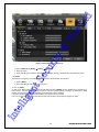
【Warnings and Cautions are indicated as follows.】
Possible injury or product damage.
Risk of minor injury or product damage.
1
Operating Instruction & User’s Guide
d
Cautions for the usage of the product.
Fir
e
CONTENTS
Lt
Information for the usage of the product.
CONTENTS
Chapter 1. Introduction ....................................................... 7
y&
1-1 MX-D series Major Features .................................................. 7
1-2 About the Product................................................................ 7
1-3 Components ....................................................................... 7
Chapter 2. Installation and Connection .................................. 8
1-4 MX-D series Name and Features of Each Part ......................... 8
1-4-1 MX-D Series Front Panel .......................................................... 8
1-4-2 MX-8D Channel Rear Panel ...................................................... 8
1-4-3 MX-16D Channel Rear Panel ..................................................... 8
rit
1-5 Installation and Connection ................................................... 9
1-5-1 Basic Connection .................................................................... 9
1-5-2 Connection of Other Devices ..................................................... 9
Se
cu
Chapter 3. Operation and Setup Tools ................................. 11
1-6 MX-D series Front Panel Button ........................................... 12
1-7 MX-D series Remote Controller ............................................ 13
1-8 Mouse ............................................................................... 14
Chapter 4. DVR Operation Setup ......................................... 15
ige
nt
1-9 MX-D series Storage Installation ........................................... 15
1-10 Power ON. ...................................................................... 16
1-11 Storage Setup ................................................................. 16
1-12 Recording Setup .............................................................. 19
1-13 Date/Time Setup ............................................................. 19
1-14 Camera / TV Setup .......................................................... 19
1-15 External Device Setup ...................................................... 19
1-16 Recording View ............................................................... 20
1-17 Backup .......................................................................... 20
1-18 DVR Information View ....................................................... 20
Chapter 5. System Operation .............................................. 21
1-19 Starting and Exiting the System ......................................... 21
ell
1-19-1 Starting the System ............................................................ 21
1-19-2 Exiting the System .............................................................. 21
1-20 Monitoring ...................................................................... 21
1-20-1 Screen Division and Auto Sequence ....................................... 21
Int
1-20-2 Channel Grouping .............................................................. 22
1-20-3 Spot................................................................................. 22
1-20-4 Menu in Monitoring Mode ..................................................... 22
1-21 System Login .................................................................. 22
2
Operating Instruction & User’s Guide
d
1-21-1 User Account and Authorization ............................................ 22
1-21-3 Logout ............................................................................. 23
1-22 Audio Recording and Playback .......................................... 23
1-22-1 Audio Recording Setup ........................................................ 24
1-22-2 Audio Live ......................................................................... 24
Lt
1-21-2 Login ............................................................................... 23
Fir
e
1-23 System Information View and Display Setup Change ............. 24
1-23-2 System Information ............................................................. 25
1-23-3 Camera Selection for Screen Setup ....................................... 26
1-23-4 Screen Brightness .............................................................. 26
1-23-5 Contrast ........................................................................... 26
1-23-6 Camera Adjustment ............................................................ 26
1-23-7 Camera Title Shown/Hidden ................................................. 27
y&
1-23-8 Screen Border Adjustment ................................................... 27
1-23-9 Screen saver ..................................................................... 28
1-23-10 Spot & Main display repeating ............................................ 29
1-23-11 TV OUT Adjustment ......................................................... 29
rit
1-24 Spot Control ................................................................... 29
1-25 Relay Out ....................................................................... 30
1-26 Search ........................................................................... 31
1-26-1 Search Mode ..................................................................... 31
1-26-2 Playback Menu .................................................................. 31
Se
cu
1-27 Calendar Search .............................................................. 31
1-27-1 Search Mode ..................................................................... 31
1-27-2 Year/Month/Day Selection .................................................... 32
1-27-3 Directory Count .................................................................. 32
1-27-4 Event ............................................................................... 32
1-27-5 Multi-Channel Search .......................................................... 32
1-27-6 Multi-Time Search .............................................................. 33
1-27-7 Multi-Day Search ................................................................ 33
nt
1-28 Playback ........................................................................ 33
1-28-1 Playback and Playback Speed Control .................................... 34
1-28-2 Smart Search .................................................................... 35
ige
1-28-3 Calendar Search ................................................................ 35
1-28-4 MULTI TIME ...................................................................... 35
1-28-5 MULTI DAY ....................................................................... 35
1-28-6 MULTI CHANNEL...........................Error! Bookmark not defined.
ell
1-28-7 Event ............................................................................... 35
1-28-8 Audio ...........................................Error! Bookmark not defined.
1-28-9 Backup ............................................................................. 36
1-28-10 De-Interace .................................................................... 36
Int
1-28-11 Display Mode ................................................................. 36
1-28-12 Status Bar ...................................................................... 36
1-29 Log Viewer...................................................................... 36
1-29-1 Log Type .......................................................................... 37
3
Operating Instruction & User’s Guide
d
1-29-2 System Log Viewer ............................................................. 38
1-30-1 Recording Types ................................................................ 38
1-30-2 Recording Setup ................................................................ 39
1-30-3 Recording Status View ........................................................ 39
1-31 Backup .......................................................................... 39
Lt
1-30 Recording ....................................................................... 38
Fir
e
1-31-1 Backup in Real-time Monitoring Mode ..................................... 39
1-31-2 Backup in Search Mode ....................................................... 40
1-31-3 Backup in Log Mode ........................................................... 40
1-31-4 Backup in Playback Mode .................................................... 40
1-31-5 Common Backup Procedure ................................................. 40
1-32 Log Backup ...................................................................... 41
y&
1-33 Setup Backup ................................................................... 42
1-34 NAS Backup.................................................................... 43
1-35 Snapshot ........................................................................ 43
1-36 PTZ Camera Control......................................................... 43
1-36-1 Conditions for Using the PTZ ................................................ 43
1-36-2 PTZ Mode ......................................................................... 44
1-36-3 PTZ Control ...................................................................... 45
rit
Chapter 6. Setup .............................................................. 46
1-37 Time .............................................................................. 46
1-37-1 Time Sever ....................................................................... 47
Se
cu
1-37-2 Date and Time ................................................................... 48
1-37-3 Standard Time Zone ........................................................... 49
1-37-4 scheduled rebooting ............................................................ 50
1-38 definition ......................................................................... 50
1-38-1 camera ............................................................................ 51
1-38-2 PTZ ................................................................................. 51
1-38-3 Event Source..................................................................... 54
1-38-4 relay ................................................................................ 57
nt
1-39 Action ............................................................................. 58
1-39-1 schedule (schedule1 - schedule4) ......................................... 58
ige
1-39-2 event ............................................................................... 58
1-39-3 recording ......................................................................... 59
1-39-4 Alarm .............................................................................. 61
1-39-5 Duration .......................................................................... 62
1-39-6 log .................................................................................. 63
ell
1-40 Schedule ........................................................................ 63
1-40-1 Enter to Schedule Menu ...................................................... 64
1-40-2 Schedule Setup ................................................................. 64
Int
1-41 Storage .......................................................................... 65
1-41-1 Max. Recording Days .......................................................... 66
1-41-2 HDD Overwrite .................................................................. 66
1-42 Network .......................................................................... 70
1-42-1 Ethernet ........................................................................... 70
4
Operating Instruction & User’s Guide
d
1-42-2 DDNS .............................................................................. 71
1-42-4 E-mail .............................................................................. 73
1-42-5 Bandwidth ......................................................................... 74
1-43 System ........................................................................... 75
1-43-1 System Menu .................................................................... 76
Lt
1-42-3 Port ................................................................................. 72
Fir
e
1-43-2 DVR Name........................................................................ 76
1-43-3 ID for Remote Controller ...................................................... 76
1-43-4 ID For Keyboard Controller ................................................... 77
1-43-5 User Registration................................................................ 77
1-43-6 Admin. Password ............................................................... 78
1-43-7 Upgrade ........................................................................... 78
1-43-8 Factory Default .................................................................. 80
y&
1-43-9 RS232C Port ..................................................................... 80
1-43-10 Alarm ............................................................................ 81
1-43-11 Alarm Setup ................................................................... 82
1-43-12 Menu Time Out ............................................................... 82
1-43-13 Language ...................................................................... 82
rit
A/P/P/E/N/D/I/X................................................................. 84
Int
ell
ige
nt
Se
cu
(1) Recommended HDD Specification................................................ 84
(2) Recommended PTZ Camera Protocol ........................................... 84
(3) Recommended USB2.0 Device ................................................... 84
5
Operating Instruction & User’s Guide
d
Figure List
Int
ell
ige
nt
Se
cu
rit
y&
Fir
e
Lt
[Figure 2-1. MX-16D Basic Connection and Device Connection] .................................................. 9
[Figure 2-2. Terminal Block TB1] ......................................................................................... 10
[Figure 2-3. Terminal Block TB1 Description] ......................................................................... 10
[Figure 4-4. Menu Window] ................................................................................................ 16
[Figure 4-5. Storage Device New Tab Window] ...................................................................... 17
[Figure 4-6. Storage Device New Tab Menu Window] .............................................................. 18
[Figure 4-7. Storage Device Save Tab Window] ..................................................................... 19
[Figure 5-8. Login Window] ................................................................................................ 23
[Figure 5-9. Recording Status Window] ................................................................................. 24
[Figure 5-10. Product Information Window] ............................................................................ 25
[Figure 5-11. Camera/TV Setup Window] .............................................................................. 26
[Figure 5-12. Display Setup Window] ................................................................................... 27
[Figure 5-13. Spot Control Window] ..................................................................................... 30
[Figure 5-14. Relay Control Window] .................................................................................... 30
[Figure 5-15. Playback Menu Window] ................................................................................. 31
[Figure 5-16. Search Window] ............................................................................................ 32
[Figure 5-17. Playback Screen] ........................................................................................... 34
[Figure 5-18. Playback Status and Control Window] ................................................................ 34
[Figure 5-19. Playback Menu] ............................................................................................. 35
[Figure 5-20. Smart Search Motion Detection Window] ............................................................ 35
[Figure 5-21. Display Mode] ............................................................................................... 36
[Figure 5-22. Log Viewer] .................................................................................................. 37
[Figure 5-23. Move to the log list of the certain time zone] ........................................................ 38
[Figure 5-24. Backup Window] ............................................................................................ 41
[Figure 5-26. PTZ Control Window (Max. Mode (Left) / Min. Mode (Right))] .................................. 44
[Figure 5-27. PTZ Mode Initial Screen] ................................................................................. 45
[Figure 6-28. Time Sever] .................................................................................................. 47
[Figure 6-29. Date and Time] .............................................................................................. 48
[Figure 6-30. Standard Time Zone] ...................................................................................... 49
[Figure 6-31. Schedule Window] ......................................................................................... 64
[Figure 6-32. Holiday Registration Window] ........................................................................... 65
[Figure 6-33. Storage Window (Local)] ................................................................................. 66
[Figure 6-34. Storage Offline] ............................................................................................. 69
[Figure 6-35. Storage Format] ............................................................................................. 69
[Figure 6-36. Storage Formatting Message in progress] ........................................................... 70
[Figure 6-37. Setup Network Window] .................................................................................. 71
[Figure 6-38. DDNS Window] ............................................................................................. 72
[Figure 6-39. Port Window] ................................................................................................ 73
[Figure 6-40. E-mail Window] ............................................................................................. 74
[Figure 6-41. Bandwidth Window] ........................................................................................ 75
[Figure 6-42. System Setup Window] ................................................................................... 76
[Figure 6-43. User Authorization Setup Window] ..................................................................... 78
[Figure 6-44. Firmware Upgrade File List Window] .................................................................. 79
[Figure 6-45. Firmware Upgrade Progressing Window] ............................................................ 80
[Figure 6-46. Alarm] .......................................................................................................... 81
[Figure 6-47. Language Selection Window] ........................................................................... 83
6
Operating Instruction & User’s Guide
d
Chapter 1. Introduction
Fir
e
Lt
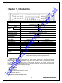
1-1MX-D series Major Features
MX-16D
System
Channel & Frame Rate
OS
Video Input
Monitor
Video
Loop
Output
Spot
Audio Input
Audio Output
Compression Format
Recording Speed
Recording Resolution
y&
16Ch - 400
8ch - 200
Embedded Linux - Built in Flash Memory
16 BNC
8 BNC
1 BNC, 1 VGA
16 BNC
8 BNC
1 BNC
Line Input : 16 RCA
Line Input : 8 RCA
Line Output : 1 RCA
[Video : Standard H.264)] / [Audio : G.723]
Max. 400 fps
Max.200 fps
Max. 704 x 576
Automatic, Continuous, Manual, Events (Sensor and Motion, Sound)/Schedule
Recording
[ Internal : Max. 2HDD, Max. 4TB ]
LCD : SXGA(1280 x 1024), TV : SDTV(720 x 576)
16 Sensors
8 Sensors
[1ea NC/NO][3ea TTL Out]
[1ea NC/NO][1ea TTL Out]
DVD-RW, USB2.0, Network
Various Network Interface ( Ethernet 10/100/1000, ADSL, Cable modem )
RS485
Se
cu
SATA HDD Max. 2ea / SATA Type DVD
Front Button, Mouse, IR Remote Controller, Keyboard Controller, Network
USB2.0 Memory Stick, Network
System Automation (Controlled by CMS)
NTP Supported
CMS / Monitoring by Web Browser / PDA
17 Languages Supported, Automatic E-mail
Power [12V/5A] / Max. Power Consumption[40W] / Operating Temperature[5-40℃]
Weight without HDD[4kg] / Dimension[430*86*270mm]
nt
Network
rit
Recording mode
Storage
Video Output Resolution
Sensor Input
Relay/TTL Output
Backup & Copy Access
Network Access
PTZ Access
Internal HDD /
Internal ODD
System Operation &
Adjustment
System Upgrade
MX-8D
Reliable Standalone DVR
ige
Others
1-2About the Product
ell
As a digital image monitoring equipment that can display images inputted from up to 16/8/4 cameras, MXDSeries digitally records high-quality images using various video recording modes and displays them as clean
quality images.
For users’ convenience, front panel button, remote controller, and mouse are provided. Powerful network
functions including remote monitoring and remote system setup modification are also supported. The maximum
recording frame rate is 480(400)/240(200)/120(100)fps.
1-3 Components
Int
After unpacking the product, check whether the following accessories are included.
- Remote Controller
- CD (CMS, CMS Manual, PDA Viewer software)
- AAA 1.5V Batteries 2ea
- Adapter 12VDC (MX-D-5A )
- User Manual
- Rack Mounting Handle (Only MX-D series)
7
Operating Instruction & User’s Guide
Lt
1-4 MX-D series Name and Features of Each Part
d
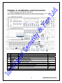
Chapter 2. Installation and Connection
The front panel of MX-D-series features an easy-to use button; various interfaces are located on the rear part.
They can easily be mounted on a standard rack using the mounting handles (Left/Right).
Fir
e
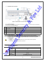
1-4-1 MX-D Series Front Panel
rit
Se
cu
1-4-3 MX-16D Channel Rear Panel
y&
1-4-2 MX-8D Channel Rear Panel
10
SPOT
11
12
TV
CAMERA IN
5
Int
ell
6
Function
Cooling system
Audio Input Connection(Line Only Input)
Video Signal loop-back Output Connection
Power cable connection to the body
Select the video input format.
Select the video output format.
PTZ Camera Control Connection
Sensor/ Relay Connection
Network Connection(ADSL, Cable Modem, Ethernet 10/100 Base-T)
VGA Monitor or LCD Monitor Connection
Audio Output Connection(Line Only Output)
CCTV monitor connection to output image from the channel
generating an event signal(Full Screen)
CCTV Monitor Connection(Divided Screen)
Video Camera Connection
nt
7
8
9
Name
FAN
AUDIO IN
LOOP OUT
DC IN
NTSC/PAL
VGA/TV
RS485
DIO
Ethernet
VGA-OUT
AUDIO OUT
ige
No.
1
2
3
4
8
Type
RCA
BNC
DA-2
Terminal Block
RJ-45
D-SUB 15P
RCA
BNC
BNC
BNC
Operating Instruction & User’s Guide
y&
Fir
e
Lt
d
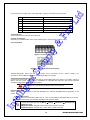
1-5 Installation and Connection
[Figure 2-1. MX-16D Basic Connection and Device Connection]
Connected Device
rit
1-5-1 Basic Connection
By referring to above [Figure 2-1], Connect the CCTV camera, CCTV monitor (or VGA monitor), and USB mouse
to the DVR and set up CONFIG SWITCH.
DVR Terminal
CCTV camera
Rear Panel Video Input
2
CCTV monitor
Rear Panel TV
3
VGA Monitor / LCD Monitor
Rear Panel VGA-OUT
4
Mouse
5
CONFIG SWITCH
Se
cu
1
Front Panel USB
Rear Panel NTSC/PAL or VGA/TV Setup
ige
nt
Refer to a further description of CONFIG SWITCH below.
1. The input video type must be either NTSC or PAL; these two types must not be used together.
2. Select the input video format (NTSC/PAL) using the CONFIG switch on the rear side of the product.
3. Select the output monitor type (VGA/TV) using the CONFIG switch on the rear side of the product.
4. CONFIG SWITCH
1) VGA Mode
Resolution of VGA Monitor is SXGA (1280*1024) and CCTV Monitor output is supported.
2) TV Mode
CCTV Monitor output is supported but No VGA mode.
ell
1-5-2 Connection of Other Devices
MX-D-series
16/8
Int
ITEM
Loop Out
OK
Spot Out
OK
Sensor
Channel
16 / 8 / 4
Relay Channel
[1ea NC/NO] [3ea TTL Out]
9
Operating Instruction & User’s Guide
DVR Terminal
SPOT Monitor(CCTV Monitor)
Rear Panel SPOT
2
Mike / Speaker
Rear Panel Audio Input / Audio Output
3
LAN Cable
Rear Panel Ethernet
4
PTZ Camera
Rear Panel Terminal Block
5
Sensor / Relay / TTL OUTPUT
Rear Panel Terminal Block)
6
Key controller
Rear Panel Terminal Block
Fir
e
1
Lt
Connecting Device
d
Connect the PTZ controller cable, audio input/output, network, and sensors as shown below.
1) SPOT Monitor
Connect Spot Monitor to the rear SPOT terminal.
y&
2) Audio Input/Output
Depending on models16ch/8ch, each of the models supports 16/8 line input and 1 line output.
rit
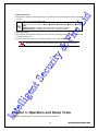
3) Terminal Block
Se
cu
[Figure 2-2. Terminal Block TB1]
[Figure 2-3. Terminal Block TB1 Description]
nt
Terminal Blocks(TB1, TB2) in the rear of the product are for connections of PTZ / Sensor / Relay / TTL
Connection. Terminal Blocks may not be available depending on the model.
ige
4) PTZ Camera/Keyboard Controller
Connect PTZ control cable; TRX+, TRX- and GND to Terminal Block(TB1);No.4 TRXD+, No.5 TRXD- and No.10
GND in the rear of DVR. You may refer to APPENDIX for supported PTZ cameras in this manual. Keyboard
controller has the same connection as PTZ camera.
PTZ Camera may not be working properly if GND is not connected.
ell
5) Sensor/Relay /TTL
Sensor and Relay are connected to Terminal Block(TB1) and Terminal Block(TB2) directly depending on the
model.
(1) Sensor Connection
Int
① Connect Sensor to Terminal Block (TB1) and S1 ~ S16 of Terminal Block (TB2) depending on the model.
② Each input terminal may be connected regardless of the channel number.
Sensor types include Normal Close (NC) and Normal Open (NO). For more information
on setup by sensor type, refer to {Menu} {Setup} {Definition} {Event Source}
{Sensor Type}.
NC(Normal Close) : Normally closed; opens when a signal is received.
NO(Normal Open) : Normally open; closes when a signal is received.
10
Operating Instruction & User’s Guide
d
(2) Relay Connection
Lt
① Outputs alarm signals to external devices such as LED and siren by relaying them to these external
devices.
Fir
e
② Connect Relay to R1 of Terminal Block (TB1).
Relay types include Normal Close (NC) and Normal Open (NO). For more information on
setup by sensor type, refer to {Menu} {Setup} {Definition} {Relay} {Relay
type}.
NC(Normal Close) : Normally closed; opens when a signal is received.
NO(Normal Open) : Normally open; closes when a signal is received.
(3) TTL Connection
① This is for the external alarm devices such as an alarm and a siren that are supplied with voltage level
LOW (0V) or HIGH (5V).
② Connect TTL device to DO1 (TTL) / DO2 (TTL) / DO3 (TTL) of Terminal Block (TB2).
Int
ell
ige
nt
Se
cu
rit
y&
The external alarm device may require the power supply depending on its type.
Chapter 3. Operation and Setup Tools
MX-D series is operated by Front Button, Remote Controller and Mouse.
11
Operating Instruction & User’s Guide
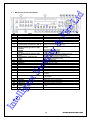
6
Reverse Play / Fast Reverse RELAY
7
Reverse Frame by Frame or TAB
STATUS
9
10
11
12
13
14/15
16
17
18
19
PAUSE
LOCK
Forward Frame by Frame or TAB
LOG
Forward Play / Fast Forward
PLAY
COPY
PTZ
SEARCH
UP/DOWN
ESC
MENU
RECORD LED
NETWORK LED
ALARM LED
21
ERROR LED
22
23
23
24
POWER LED
SELECT
MOVE & DISPLAY
IR Sensor
USB port
POWER
Int
ell
26
ige
25
nt
20
Se
cu
8
Feature
Brand Name and Model Name
Recording start/stop for all channels
USB Mouse or Memory USB Stick
System Login or Number input
CD-RW, DVD-RW
Backward Playback/Rewind (in Playback mode)
Relay Control (in Monitoring mode)
Backward Playback Frame by Frame (in Playback
mode)
View System Configuration
Pause (in Playback mode)
Lock (in Monitoring mode)
Playback Frame by Frame (in Playback mode)
System Log View(in Monitoring mode)
Playback/Fast Forward (in Playback mode)
Play back (in Monitoring mode)
Copy recording data
Change Pan/Tilt/Zoom mode
Search recording data
Speed control
Exit the current menu or selects the upper menu.
Various Modes
Green LED turned on upon HDD operation
Green LED turned ON during remote access
Red LED turned on upon the occurrence of event or
motion.
Red LED turned on upon fan defect or recording
interruption.
Power LED On/Off
Select the menu or sequence
Select the menu or change the display mode
Remote controller input sensor
Connection port to the USB mouse and USB memory
stick
Turn the system power ON or OFF
y&
Name
LABEL
RECORD
USB
Number (0~9)
ODD
rit
No.
1
2
3
4
5
Fir
e
Lt
d
1-6 MX-D series Front Panel Button
12
Operating Instruction & User’s Guide
d
1-7 MX-D series Remote Controller
Lt
A) Basic Control Button
Turn the system power
ON or OFF.
POWER
Record all channels
recording all channels.
or
stops
NUMBER
Enable input of numeric data.
ID
Set up the remote controller ID.
Fir
e
~
RECORD
B) System operation and setup buttons
Data, Schedule, System Set up
ESC
Exit the current menu
or select the upper menu.
y&
MENU
Search recorded images.
SELECT
Select the category or execute
automatic screen conversion.
COPY
Copy Recorded Video.
PTZ
Shift to PTZ camera control mode.
MOVE
Move from one category to another
or change the display mode.
rit
SEARCH
Se
cu
UP/
DOWN
Speed and Volume Control
C) Search Button (Playback mode)
Play/Fast-forward
Frame by Frame
Play frame by frame
Pause
Pause
ell
ige
nt
Play /
Fast Forward
Reverse Frame by Frame
Reverse play frame by frame
Reverse Play /
Fast Reverse
Reverse play/ Rewind
Int
D) Buttons for other features (Monitoring mode)
PLAY
Play the recorded images.
LOG
Enable viewing the system
log list.
13
Operating Instruction & User’s Guide
Locking the system
STATUS
View system information and changes the
display setup.
RELAY
View Relay Status and Manual Operation.
Fir
e
Lt
d
LOCK
※ Setting up the remote controller ID
Example) When the remote controller ID is set to 1.
Press the {ID} button, enter a two-digit remote controller ID, and press the {ID} button again.
,
,
y&
To control all DVRs with different IDs, set the remote controller ID to 999.
1-8Mouse
rit
The USB mouse can be used to operate the system. The mouse pointer as below photo will be shown if a mouse
is connected to USB terminal at front panel.
Mouse Control supports features are shown below.
Se
cu
Click on the right button
Monitoring Mode / Move from Play Mode to
Monitoring Menu / Pop up or remove Play
Menu.
Show sub-folder of the certain Menu window.
Select Menu.
Select Menu.
Move a certain window.
Int
ell
ige
nt
Click on the left button
Double click on the left button
Click and drag the left button
14
Operating Instruction & User’s Guide
Lt
d
Chapter 4. DVR Operation Setup
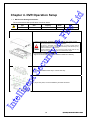
1-9 MX-D series Storage Installation
※ The recommended HDD specification are shown below.
Size
Capacity
Buffer
SATA I, II
3.5“ 1, 2 Flat
Up to 2TB
over 8MB
RPM
Fir
e
Type
over 7200
y&
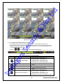
1) Using a screw driver, unscrew and take off the top case of the product.
1) Normal termination of the system and fully unplugged power code
are required before conducting HDD installation.
2) Touch a grounded metal substance or ground yourself before
installing HDD in order to reduce static electricity. Static electricity may
cause a malfunction of the product.
3) After installing HDD, Do not connect to power supply with the top
case opened. The top case must be covered before usage.
Se
cu
rit
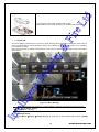
2) Unscrew and separate the HDD bay.
Align screw holes and screw and fix additional HDD onto HDD bay.
4) As per the photo, Screw the HDD bay and HDD and DVD
Int
ell
ige
nt
3) Screw the additional HDD bay to current HDD bay
15
Operating Instruction & User’s Guide
d
Lt
Fir
e
5) Connect the power cable and data cable to HDD.
Reassemble the top case by reversing 1) to finalizing HDD installation.
1-10Power ON.
ell
ige
nt
Se
cu
rit
y&
Check the adapter (12VDC/5A) and connect the power. Booting will be initiated by pressing the power button in
the front panel. Booting is progressed step by step by VGA outputting or a color bar test screen for TV outputting,
Live screen and a clock.
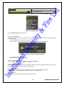
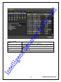
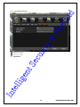
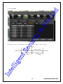
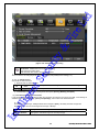
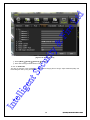
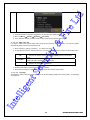
Menu window pops up by clicking the right button of the mouse or pressing [MENU] button in the front panel as
shown below.
[Figure 4-4. Menu Window]
Int
ID and Password are required for a initial installation. Default ID and Password are shown below.
[ Local Admin : 00000 ]
[ admin : 1111111 ]
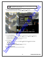
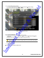
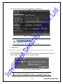
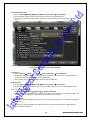
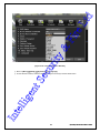
1-11 Storage Setup
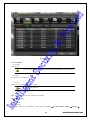
① Select {Menu} {Setup} {Storage Device}. As shown below, newly installed HDD is shown at {NEW}
tab.
16
Operating Instruction & User’s Guide
Se
cu
rit
y&
Fir
e
Lt
d
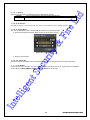
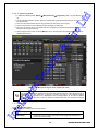
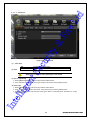
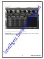
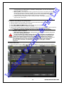
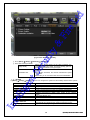
Indication of “{ }” refers to one provision of the menu. Indication of “” refers to a subprovision. Example> {Menu} {Setup} : go to Setup that is a sub-provision of Menu.
[Figure 4-5. Storage Device New Tab Window]
{New} tab is a manager that manages all newly introduced storage. All newly recognized devices
are managed and allocated as a saving or backup storage in {New}.
② Move a focus onto {NEW} tab using the arrow keys and select.
Int
ell
ige
nt
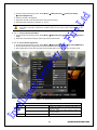
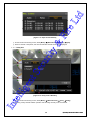
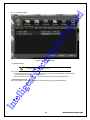
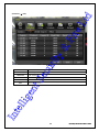
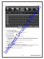
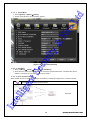
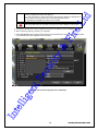
③ Select Hard Disk.
17
Operating Instruction & User’s Guide
d
Lt
Fir
e
y&
rit
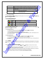
Direct Initialize
Backup Initialize
Se
cu
[Figure 4-6. Storage Device New Tab Menu Window]
Changes the selected storage into a dedicated direct storage.
Changes the selected storage into a backup storage.
{New} At least, one storage shall be selected as a dedicated storage.
Otherwise, the data cannot be stored in real time.
④ Select {Direct-Init} and follow {Direct-Init} procedure.
nt
{Direct-Init} procedure may take time.
Int
ell
ige
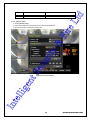
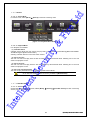
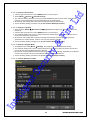
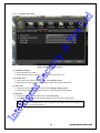
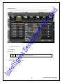
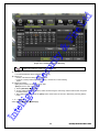
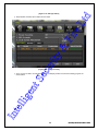
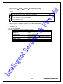
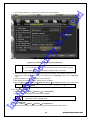
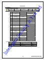
⑤ When it is completed, HDD is removed from {New} tab and shifted to {recording} tab.
⑥ Move to {recording} tab and select.
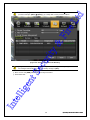
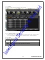
⑦ As shown below, it is indicated as [ACTIVE/HEAL..] in {Status(SW/HW)}, and HDD setup is completed.
18
Operating Instruction & User’s Guide
d
Lt
Fir
e
y&
rit
Se
cu
[Figure 4-7. Storage Device Recording Tab Window]
More detail description for HDD and Storage Device; check [6-4 Storage
Device].
1-12 Recording Setup
① Select {Menu} {Setup} {Action}-> {Recording}.
② Setup for [Recording Resolution]/[Recording Quality]/[Mode]/[Recording Frame]/[Audio]/[Motion
Detection]/[Sensor Detection]/[Event] and Alarm Output are available.
nt
1-13 Date/Time Setup
① Select {Menu} {Set up} {Time}.
ige
② Set up for [Time server]{Date and Time}{Standard Time Zone} are available.
1-14 Camera / TV Setup
① Select {Menu} {Set up}->{Definition}->{Camera}->{Adjust}
② Set up for [Brightness/Contrast/Color/Hue/Camera Adjustment/TV OUT Adjustment] are available.
ell
1-15 External Device Setup
① Set up External Device. For more information, check [5-4 Audio Recording and Playback] [5-6 Spot
Control] [5-7 Relay Out] [[6-5 PTZ] [6-6 Network] [6-2-5 Alarm Output] [6-7-10 Alarm] [6-7-11 Alarm Time
Int
Setup].
19
Operating Instruction & User’s Guide
d
1-16 Recording View
Lt
① Select {Menu} {Search} {Calendar Search/Last Hour Playback/First Hour Playback/Move to
Last Playback}.
② For more information, check [5-8 Search] [5-9 Calendar Search] [5-10 Playback].
① Backup is available in Monitoring, Search, Log and Playback Mode.
② For more information, check [5-13 Backup].
③ Log backup: You may save log list through USB memory stick.
④ Setup backup: You may save log list through USB memory stick.
1-18 DVR Information View
① Move to {Menu} {Miscellaneous} {DVR Info.}.
Fir
e
1-17 Backup
Int
ell
ige
nt
Se
cu
rit
y&
Detail information for product functions are described below in this manual.
20
Operating Instruction & User’s Guide
d
Chapter 5. System Operation
1-19-1 Starting the System
With the power connected, press the Power button.
① After the system is booted, images of all connected channels will be displayed.
Fir
e
1-19-2 Exiting the System
Lt
1-19 Starting and Exiting the System
※ The default password for the local administrator is “00000.”
※ To change the password, select {Main Setup} {System} {Local Administrator’s
Password}.
1-20 Monitoring
Various Screen Division and Auto Sequence.
Channel Grouping.
Spot
Menu Controlling in Monitoring Mode
y&
Press the Power button on the remote controller.
On the password input screen, enter a new password using the numeric buttons and the arrow keys.
After authentication is completed, the system will be terminated.
Full Screen (16 groups)
Se
cu
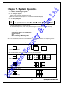
1-20-1 Screen Division and Auto Sequence
rit
After the system is booted, images will be displayed on a screen divided into [16/9/4] according to its setting. In
case of 16 channels DVR, the screen can be divided into 1, 4, 9, and 16 sub-screens. Auto-sequencing from is
available in each mode.
nt
Use the Full Screen mode.
To view a certain channel, select the desired channel using the numeric buttons.
ige
4Sub-Screen (4 groups)
Use the 4 Sub-Screen button.
ell
9Sub-Screen (2 groups)
Use the 9 Sub-Screen button.
Int
1 2 3 4
5 6 7 8
9 101112
13141516
16Sub-Screen(1 group)
21
Operating Instruction & User’s Guide
d
Use the 16 Sub-Screen button.
Lt
※ The user can view an image on full screen by double-clicking the 4/9/16 Sub-Screen mode. Double-click
any part of the screen to return to the previous mode.
Fir
e
※ Auto Sequence
Auto Sequence is to rotate images at an interval of the certain time in 1/4/9 Sub-Screen Mode. It changes to
Auto Sequence Mode if you select {Menu} {Miscellaneous} {Display Mode}{Sequence} in 1/4/9
Sub-Screen Mode. Using the Up/Down button, the user can select the interval from 1 second to 10 seconds
(to set the interval, however, multiple cameras should be connected).
y&
1-20-2 Channel Grouping
Channel Grouping is to change the image location in the screen between channels.
On the real-time monitoring screen, select {Menu} {Miscellaneous} {Channel Grouping}.
On the monitoring screen, go to the channel selection window and select the channel to be changed in the
group. Then the selection window pops up.
On the selection window, select a channel using the arrow keys and the Select button.
The Image location of the each channel is changed.
※ Group Setup is not supported for the 1-split mode.
※ The user can change the channel location in the group using the mouse.
※ Changing the screen division mode causes other division modes to be changed as
well.
Se
cu
rit
1-20-3 Spot
※ Spot function is only available in MX-D series.
Spot is to output a channel that is set with a certain function. Spot has an independent monitor and output and
only full screen mode is available.
① Event Spot
Event Spot is to show a channel quickly that is set with the Event function in case events (sensor and motion)
occur. The event check interval is one second. If events are detected in many channels, it shows a channel with
the last event. Move to {Menu} {Setup} {Action} {Alarm Output} {Event Spot}.
② Manual Spot
User can designate a spot channel manually. Move to {Menu} {Control} {Spot} and select a channel.
③ Sequence Spot
User can select more than one channel in Manual Spot and have a sequential image through Spot. Move to
{Menu} {Control} {Spot} {Sequence}.
nt
1-20-4 Menu in Monitoring Mode
User can control all functions available in Monitoring Mode in {Menu}.
① Press the Menu or right-click mouse button. The {Menu} will then appear.
ige
② Select the desired item using the arrow keys or mouse.
③ Press the ESC button or right-click mouse button to hide the menu.
1-21 System Login
ell
1-21-1 User Account and Authorization
System users are divided into local administrators and general users.
The local system administrator can use all functions.
Int
Local Admin
User
The local administrator can use all functions: System Power On/Off, Setup,
Monitoring, and Playback (remote access is not available, however).
Up to 15 users are allowed. Each user can access the functions depending on the
given authorities.
For Authorization Setup, Move to {Monitoring Menu} {Setup} {System}
{4. User Registration}.
※ Functions available for Authorization Setup
22
Operating Instruction & User’s Guide
Enable viewing real-time images upon network access.
Playback
Enable viewing the Recorded Screen.
Copy (Download)
Enable copying and downloading files from the network.
PTZ Control
PTZ camera control
Recording, Recording Schedule, System, Storage, Time, NTP,
PTZ, Network Setup, Camera/TV Setup
Remote network upgrade
Lt
Network Upgrade
View
Covert
Channels
Fir
e
Setup
d
Network Live
Enable viewing Covert channels.
[Figure 5-8. Login Window]
ige
nt
Se
cu
rit
y&
1-21-2 Login
For security purpose, user must log in first to use {Monitoring Menu}.
ell
① On the real-time monitoring window, select {Menu} {Login}. The login window will then appear as
shown in Figure 4-9.
② Enter the password or select the cancel.
③ You can select the space of password and enter alphabets for the password at the pop-up window.
1-21-3 Logout
After logging out, the user cannot use {Menu}.
① On the real-time monitoring screen, select {Menu} {Logout}.
Int
1-22 Audio Recording and Playback
16ch
8ch
Each model; 16ch / 8ch supports 16/8 audio channels
Audio recording for video channel 1~16 is available.
Audio recording for video channel 1~8 is available.
23
Operating Instruction & User’s Guide
③ Set up the audio.
1-23 System Information View and Display Setup Change
Fir
e
1-22-2 Audio Live
① On the real-time monitoring screen, select {Menu}-> ( {Miscellaneous}->( {Control}.
② Select the audio channel in {Audio} tab.
Lt
d
1-22-1 Audio Recording Setup
① On the real-time monitoring screen, select {Menu} {Setup}{Action}.
② Select {Recording} {Audio} using the arrow keys and the Select button.
nt
Se
cu
rit
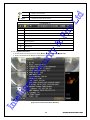
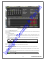
y&
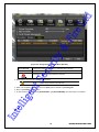
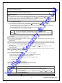
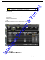
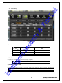
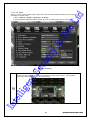
Audio/Recording Status/Channel Title/Connection Indicator/Time/HDD status are displayed as shown below.
[Figure 5-9. Recording Status Window]
ige
※ Recording Event / Recording mode disoplay ※
Sensor recording
Recording
Video recording.
Mode
Audio recording
Recording
Int
ell
Event
Motion recording
Audio recording.
※ Live Display ※
Video is not connected or Video is covert
24
Operating Instruction & User’s Guide
d
Audio is set activated.
Audio is set silent.
Camera has been disconnected.
Lt
No Signal
Fir
e
※ Control Bar ※
DVR ID
①
1ch display mode
4ch display mode
8ch display mode
16ch display mode
⑦
Date / Time
⑧
HDD Status
⑨
Playback
y&
Auto Sequence
rit
1-23-2System Information
① On the real-time monitoring screen, select {Menu} {Miscellaneous}{DVR Info.}.
Int
ell
ige
nt
Se
cu
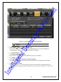
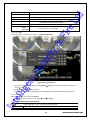
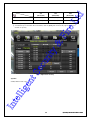
② Product information mode will then be displayed as shown below.
[Figure 5-10. Product Information Window]
25
Operating Instruction & User’s Guide
1-23-3 Camera Selection for Screen Setup
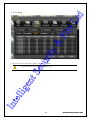
① On the real-time monitoring screen, select {Menu} {Set Up} {Definition}.
Lt
d
ID is an identification(1~99, 255) of the product. The remote controller ID must match
the identification to control DVR system.
Se
cu
rit
y&
Fir
e
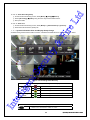
② Select a camera for Screen Setup. If you tick on all Channels, you can set up screen over all channels.
[Figure 5-11. Camera/TV Setup Window]
1-23-4 Screen Brightness
① On the real-time monitoring screen, select {Menu} {Miscellaneous} {Adjust} {Brightness}.
nt
② Select a channel to be adjusted.
③ Adjust the brightness of the selected channel using the arrow keys.
④ Adjust the other channels by repeating ② and ③.
ige
1-23-5 Contrast
① On the real-time monitoring screen, select {Menu} {Miscellaneous} {Camera/TV Setup}
{Contrast}.
② Select a channel to be adjusted.
③ Adjust the contrast of the selected channel using the arrow keys.
ell
④ Adjust the other channels by repeating ② and ③.
Int
1-23-6 Camera Adjustment
You can adjust a position of each camera by Up/Down/Left/Right.
26
Operating Instruction & User’s Guide
Lt
② Select a channel to be adjusted.
③ Adjust the contrast of the selected channel using the arrow keys.
d
① On the real-time monitoring screen, select {Menu} {Miscellaneous} {Camera/TV Setup}
{Camera Adjustment}.
④ Adjust the other channels by repeating ② and ③.
Fir
e
Moving the camera, down, right, or left excessively may cause black or gray areas to appear on
the screen. The level at which such condition does not occur is the proper control range for the
camera.
1-23-7 Camera Title Shown/Hidden
① On the real-time monitoring screen, select {Menu} {Miscellaneous} {Display Setup} {Camera
Title}.
② Select the On/Off status using the arrow keys and the Select button.
y&
1-23-8 Screen Border Adjustment
① On the real-time monitoring screen, select {Menu} {Miscellaneous} {Display Setup} {Border}.
ell
ige
nt
Se
cu
rit
② Select the desired item using the arrow keys and the Select button.
③ After assigning the setup value per field, press the [Exit] button to exit the Border Line setup mode.
Field
Int
Mode
setup
Type
Setup Value
On
Off
Internal
[Figure 5-12. Display Setup Window]
Border setting fields
Description
Display the border for each channel screen in
varying modes.
Hide the border for each channel screen in
varying modes.
Hide the external border line.
27
Operating Instruction & User’s Guide
2, 4
Black, White, Red, Green, Blue
Set the thickness of the border.
Set the color of the border.
Se
cu
rit
y&
② Select the desired item using the arrow keys and the Select button.
③ Set up the Duration, starting and waiting time.
Fir
e
1-23-9Screen saver
① Select {Screen saver}
d
Display all border lines.
Lt
Thickness
Color
All
Int
ell
ige
nt
[Figure 5-14. Screen Saver]
28
Operating Instruction & User’s Guide
Se
cu
rit
y&
Fir
e
Lt
② Set up the repeating time(1-10) and sequence duration.
d
1-23-10Spot & Main display repeating
① Select {Spot or Main display repeat}{menu}{miscellaneous} (display setting}
[Figure 5-15. Spot Sequence time]
1-23-11TV OUT Adjustment
TV OUT Adjustment is to move the TV OUT screen Up/Down/Left/Right.
① On the real-time monitoring screen, select {Menu} {Miscellaneous} {display Setting} {TV}
Adjustment}.
nt
② Adjust the CCTV monitor screen up/down or Right/Left using the arrow keys.
ige
Moving the monitor up, down, right, or left excessively may cause black or gray areas to appear
on the screen. The level at which such condition does not occur is the proper control range for
the monitor.
1-24Spot Control
Int
ell
※ Spot function is only supported in MX-D series
29
Operating Instruction & User’s Guide
d
Lt
Fir
e
y&
[Figure 5-13. Spot Control Window]
① On the real-time monitoring screen, select {Menu} {Miscellaneous} {misc} {Spot}.
② Select a channel or Sequence, and then the selected channel screen will be displayed.
ell
ige
nt
Se
cu
rit
1-25 Relay Out
[Figure 5-14. Relay Control Window]
Int
① On the real-time monitoring screen, select {Menu} {Miscellaneous} {misc} {Relay}.
② Selecting a relay channel enables operation and canceling the relay. from normal state.
30
Operating Instruction & User’s Guide
d
1-26 Search
y&
Fir
e
Lt
1-26-1 Search Mode
For Search mode, select {Menu} {Search} in real-time monitoring mode.
[Figure 5-15. Playback Menu Window]
1-26-2 Playback Menu
Four Playback are available.
rit
(1) Calendar Search
Calendar Search allows the user search and play back by [Year/Month/Day/Hour/Minute],[Multi-Channel/MultiTime/Multi-Day]and [Motion/Sensor/Audio].
Selecting Calendar Search moves to the search window.
Se
cu
(2) Go To The Last
The user can search and play back the last recorded data by Multi-Channel Mode. Selecting Go To The Last
shifts to the playback screen.
(3) Go To The First
The user can search and play back the first recorded data by Multi-Channel Mode. Selecting Go To The First
shifts to the playback screen.
(4) Go to The Last Played Time
The user can play back from the last played time by Multi-Channel Mode.
nt
※ Go To The First and Go To The Last are only available in {Multi-Channel}.
ige
1-27 Calendar Search
1-27-1 Search Mode
On the real-time monitoring screen, select {Menu} {Search} {Calendar Search} and then a searching
Int
ell
window pops up as shown below.
31
Operating Instruction & User’s Guide
d
Lt
Fir
e
y&
rit
Se
cu
[Figure 5-16. Search Window]
1-27-2 Year/Month/Day Selection
Select the desired [Year/Month/Day]. The color of the icon at the top-left day square in the calendar indicates the
recording status.
1-27-3 Directory Count
nt
① Every time when the user changes the time at {Menu} {Setup} {Time} {Date and Time} tab, a new
folder(Directory) is created and files saved in the folder before the time change is indicated sky-blue in the
file list.
② Selecting a file in blue-sky leads to a selection window popup and the user can select a file in different
folder (before time change).
※ Searching by the file list is only available in Multi-Channel Search.
Recorded image files with the current set time.
Recorded image files before the time change.
ige
Current
Old_Number
1-27-4 Event
Event is to search the data by the events. Select [All/Motion/Sensor/Audio].
ell
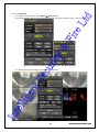
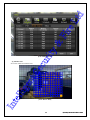
1-27-5 Multi-Channel Search
Multi-Channel Search is to play the recorded image of the different channel over a certain designated time.
Int
① Using the arrow keys and the Select button, select the desired Year/Month/Day in the activated calendar
window.
② On the calendar window, select the desired search date. The recorded one-hour video of each channel is
then displayed in a bar graph.
Green
Continuous recording is in progress.
32
Operating Instruction & User’s Guide
Blue
Sensor recording is in progress.
Yellow
d
Motion recording is in progress.
Lt
Red
Audio recording is in progress.
③ Move the time line to a specific time point using the arrow keys or the numeric buttons and press the
Search button.
Fir
e
④ Selecting the time causes the recorded video for each channel to be displayed as a bar graph in minute
units.
⑤ Move the time line to a certain time point using the arrow keys and the numeric buttons and press the
Select button. Playback will then start from the specified time point.
1-27-6 Multi-Time Search
The user can play back the video contents of a certain channel recorded in different time zones.
Multi-time data can be searched in Multi-time Search mode.
The user can search data by date as in the Multi-Channel Search mode.
Time zones and channels may be viewed by selecting the desired date.
Select the start time and the channel using the arrow keys.
The hourly recorded video of the selected channel will then be displayed as a bar graph in minute units.
Move the time line using the arrow keys and the numeric buttons and specify the time. Afterward, press
the Start button and play back the contents.
y&
①
②
③
④
⑤
rit
※ A different time zone means continuous 16 hours.
Se
cu
1-27-7 Multi-Day Search
The user can play back the video contents of a certain channel recorded in different days.
Multi-time data can be searched in Multi-Day Search mode.
① The user can search data by date as in the Multi-Channel Search mode.
② The date list and the recording status from the date the user selects, are viewed by selecting the desired
date.
③ Select the start time and the channel using the arrow keys.
④ The recorded video of the selected channel will then be displayed as a bar graph in minute units.
⑤ Move the time line using the arrow keys and the numeric buttons and specify the time. Afterward, press
the Start button and play back the contents.
1-28 Playback
nt
※ A different time zone means continuous 16 hours.
Int
ell
ige
There are five routes to play the recorded image.
Playback in Calendar Search
Select {Playback} in {Menu} {Search} {Calendar Search} {Search}.
Playback in Go To The Last
Select {Menu} {Search} {Go to The Last}.
Playback in Go To The First
Select {Menu} {Search} {Go To The First}.
Playback in The Last Played Time
Select {Menu} {Search} {The Last Played Time}.
Playback in Log View
After selecting {Menu} {Miscellaneous} {Log Viewer}, select or double-click the time line listed to
play.
33
Operating Instruction & User’s Guide
d
Lt
Fir
e
y&
rit
Se
cu
[Figure 5-17. Playback Screen]
1-28-1 Playback and Playback Speed Control
① In Playback mode, the user can play back video contents using the button functions below.
② After the data is played to the end, the data of the next time zone will be automatically searched and
played (this function is possible only in Multi-channel Playback mode; both backward playback and
forward playback are possible).
③ Pressing
buttons, the user can adjust the playback speed by
(ⅹ1) / (ⅹ2) / (ⅹ4) / (ⅹ8) / (ⅹ16) / (ⅹ32).
nt
[Figure 5-18. Playback Status and Control Window]
Description of the Search Buttons
Name
ige
Button
Forward Play / Fast Forward
ell
Forward Frame by Frame
Pause
Int
Reverse Frame by Frame
Reverse Play / Fast Reverse
Features
Press one time - Fast forward (ⅹ2)
Press two times - Fast forward (ⅹ4)
Press three times - Fast forward (ⅹ8)
Press five times - Fast forward (ⅹ32)
Pressing one more time in x32 leads to x1 back.
Playback frame-by-frame
Pause
Pause
Reverse playback frame by frame
Pause
Press one time - Fast reverse (ⅹ2)
Press two times - Fast reverse (ⅹ4)
Press three times - Fast reverse (ⅹ8)
Press five times - Fast reverse (ⅹ32)
Pressing one more time in x30 leads to x1 back.
34
Operating Instruction & User’s Guide
ESC
d
Exit to Playback Mode.
Lt
Status bar indicating information of the hourly
recorded image data
y&
Fir
e
Selecting the right-mouse button or menu button in Playback Mode pops up the {Playback Menu}.
[Figure 5-19. Playback Menu]
Items in {Playback Menu} are shown below.
rit
1-28-2 Smart Search
This function is used to search an image with the object movement at a specific zone fast. Searching by each
channel is available.
Se
cu
① Move to Smart Search and select the desired channel.
② Then, it shifts to 1 channel mode and the searching starts with a window shown below.
nt
[Figure 5-20. Smart Search Motion Detection Window]
ige
③ It may take time during the searching.
④ Start the playback after the searching.
1-28-3 Calendar Search
Move to Calendar Search in {Menu} {Search} {Calendar Search}.
ell
1-28-4 MULTI TIME
Multi-Time is to play the recorded image of the different time over a certain designated channel. The lineup of the
recorded image of the different time is the most recent-bottom.
Int
1-28-5 MULTI DAY
Multi-Day is to play the recorded image of the different day over a certain designated channel.
The lineup of the recorded image of the different time is the most recent-bottom.
1-28-6 Event
Event is to play the recorded image with [All/Motion/Sensor/Audio].
35
Operating Instruction & User’s Guide
Snapshot
d
1-28-7 Backup
Save the backup image and captured image into [CD/External Storage].
Backup
Save the backup image data into [CD/External Storage].
Lt
Capture and save an image of screen being monitored.
1-28-8 De-Interace
Fir
e
De-Interlace function could be selected (On/ Off) for the playback of 4CIF recorded images.
1-28-9 Display Mode
The user can divide the screen in Playback Mode as same as in Monitoring Mode.
y&
① Select Screen Mode and Screen Mode window as shown below pops up.
rit
[Figure 5-21. Display Mode]
② Select [1/4/9/16 Mode].
1-29 Log Viewer
Se
cu
1-28-10 Status Bar
Select Activation or Deactivation below Playback Mode [Figure 5-23. Playback Status and Control Window].
Int
ell
ige
nt
DVR records all Log information over the system operation including Power on/off, System Setup and Network
Access. Move to {Menu} {Miscellaneous} {Log Viewer} to see the logs.
36
Operating Instruction & User’s Guide
d
Lt
Fir
e
y&
rit
[Figure 5-22. Log Viewer]
Se
cu
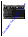
1-29-1 Log Type
Logs related to power ON/OFF, file copy/backup failure, setup start/end,
playback, and other basic system operations
Logs related to recording, e.g., motion detection and sensor detection,
Audio detection
Logs related to network operations e.g., network login, network logout,
and network live
Logs related to system operation failures, e.g., signal loss and network
connection failure
Logs related to all system operations
Normal
Recording Event
Network
Fail
Int
ell
ige
nt
All
37
Operating Instruction & User’s Guide
nt
Se
cu
rit
y&
Fir
e
Lt
d
1-29-2 System Log Viewer
① In real-time monitoring mode, {Menu} {Miscellaneous} {Log Viewer}, then, Log List Window pops
up.
② On the activated calendar window, Select the desired date (year/month/date) using the arrow keys and
the Select button.
③ The user can check the time and the log type using the arrow keys in the log list.
④ Use the menu button to check the logs by time and type on each page.
⑤ The user can shift the focus to a certain time zone for playing the certain time (playback will start from the
time point when logs are saved).
⑥ Click the right-mouse button or select {Menu} button in the front panel and select {Hour} to move the
desired log time zone.
[Figure 5-23. Move to the log list of the certain time zone]
ell
ige
Time Changed Log Data View
The stored data folder is updated each time the user changes the time. A blue triangular icon is
displayed on the date each time a change is made in the date on the calendar window.
Otherwise, a red triangular icon is displayed on the unchanged date. To view the log details,
select the desired date with a red icon. Selecting a date with a blue icon causes the changed
date list to appear.
1-30 Recording
Int
1-30-1 Recording Types
It supports various recording types as shown below.
Recording Type
Automatic
Description
Set the event recording frame and general recording frame separately.
Depending on the set value, select the recording type automatically and
proceed with the recording.
38
Operating Instruction & User’s Guide
Motion
Sensor
Audio
Fir
e
Continuous
Lt
d
When motion, sensor and audio are detected, the event recording frame
will be selected. Otherwise, the general recording frame will be selected.
Continuous recording will be initiated based on the general frame value.
When motion is detected, recording will be initiated based on the event
frame value.
When input signal from an external sensor is generated, recording will be
initiated based on the event frame value.
When audio is detected, recording will be initiated based on
the event frame value.
1-30-2 Recording Setup
Go to {Menu} {Setup} {Recording} for Recording Setup. For more information, move to {Menu} {Setup}
{Recording}} {Recording}.
y&
1-30-3 Recording Status View
(1) Recording Status by Color
Green
Continuous recording is in progress.
Red
Motion recording is in progress.
Blue
Sensor recording is in progress.
Yellow
Audio recording is in progress.
Se
cu
(3) Stopping Record All
rit
(2) Starting and Stopping Record All
In real-time monitoring mode, the user can start or stop the recording of all channels by selecting {Menu}
{Miscellaneous} {Record On/Off}.
① In real-time monitoring mode, select {Menu} {Miscellaneous} {Record On/Off}.
② Enter the password of the local system administrator.
③ On the recording stop confirmation window, select the(Yes) button.
④ Any channel recording in progress will then stop, and the corresponding status will be displayed on the
recording status window.
(4) Starting Record All
① In real-time monitoring mode, select {Menu} {Miscellaneous} {Record On/Off}.
1-31 Backup
nt
② On the login window, enter the password of the local system administrator.
③ The recording of all channels will then start based on the previous setting, and the recording status will
be displayed.
ige
To back up data, the PC shall be equipped with CD and DVD or connected with a storage device such as HDD,
CD and DVD via the USB 2.0 port. The user can back up data in real-time monitoring, search, log, or playback
mode.
ell
1-31-1 Backup in Real-time Monitoring Mode
① In real-time monitoring mode, select {Menu} {Backup} {Backup}. The backup menus will then
appear.
Int
② The automatic backup time is set to 5 minutes before the Copy (Backup) button is pressed, and the end
time, to the time the Copy (Backup) button is pressed.
③ All channels containing data at the time of backup are backed up automatically. Depending on the divided
screen mode, however, only those channels that can be viewed may be selected.
④ For the remaining backup procedures, see {5-13-5 Common Backup Procedure}.
39
Operating Instruction & User’s Guide
d
Lt
1-31-2 Backup in Search Mode
① Click the right-mouse button or select {MENU} button in the front panel.
② Select {Menu} {Search} {Calendar Search}.
Fir
e
③ The automatic backup start time is set to the year/month/date/hour/minute set in search mode, and the
end time, to the last minute/second of the data existing at the selected time.
④ All channels with existing data at the time of backup are backed up automatically.
⑤ For the remaining backup procedures, see {5-13-5 Common Backup Procedure}.
1-31-3 Backup in Log Mode
① Select a date in {Menu} {Miscellaneous} {Log Viewer} and select a log related to the data to be
backed up.
② Click the right-mouse button or select {MENU} button in the front panel.
y&
③ The automatic backup time is set to 5 minutes before the selected log is generated, and the end time, to
the time the selected log is generated.
④ All channels with existing data at the time of backup are backed up automatically. If a log has been
generated for a specific channel, however, then only that channel is selected.
⑤ For the remaining backup procedures, see {5-13-5 Common Backup Procedure}.
1-31-4 Backup in Playback Mode
① In Playback mode, select {Menu} {Backup}. Any playback in progress at this time will stop.
② The automatic backup time is set to 5 minutes before the Copy (Backup) button is pressed, and the end
time, to the time the Copy (Backup) button is pressed.
Int
ell
ige
nt
Se
cu
1-31-5 Common Backup Procedure
rit
③ All channels containing data at the time of backup are backed up automatically. Depending on the divided
screen mode, however, only those channels that can be viewed may be selected.
④ For the remaining backup procedures, see {5-13-5 Common Backup Procedure}.
40
Operating Instruction & User’s Guide
d
[Figure 5-24. Backup Window]
Lt
① [Figure 5-29] shows the initial backup window menus.
② A list of devices that can be selected as well as simple information on the currently selected devices are
outputted.
③ Selecting a device by pressing the Select button causes the free space and total capacity for the selected
device to be displayed.
Fir
e
④ Selecting a device causes the directory name based on the initial values for the time and channel to be
displayed and the size of the file to be backed up to be calculated.
⑤ The directory name is set up using the backup time. The first 12 digits are determined by the
year/month/date/hour/minute/second for From, and the 12 digits in the middle, by the
year/month/date/hour/minute/second for To. The last 2 digits are determined by the number of folders in
the selected device.
⑥ Selecting a device enables selecting the backup time as well. As a rule, the From time cannot be later
than the To time, and the To time cannot be earlier than the From time.
⑦ To change the start and end time, press the Select button after choosing the start and end time. Change
year/month/date/hour/minute/second by using arrow keys and press ESC button.
y&
⑧ Changing the backup time causes the name of the directory to be backed up to be changed as well.
⑨ If the file to be backed up exceeds the free space, its size is displayed in a yellow box in case the selected
device is capable of rerecording and in a red box if not.
rit
If the backup storage device is not formatted, in case the box displaying the size of the
file to be backed up is displayed in yellow, and if backup is executed by pressing the
Copy (Backup) button, a prompt asking whether to erase the device will appear as
shown below. Selecting [YES] causes the storage medium for the selected device to be
erased.
Se
cu
⑩ Press the Copy (Backup) button. A prompt asking whether to proceed with the backup or not will then be
displayed.
※ Select [Yes] to back up the data or [No] to stop the backup. Otherwise, press the [Cancel]
button to return to device selection mode on the backup window.
⑪
Select {Yes} to continue the backup.
1-32 Log Backup
Int
ell
ige
nt
All of recorded log data such as Normal/ Recording Event/ Network/ Failure could be backed up.
[Figure 5-26. Backup and Sub-menu log backup window]
41
Operating Instruction & User’s Guide
y&
Fir
e
Lt
d
① You can start after the setup at {Menu} {Backup} {Log Backup}.
rit
[Figure 5-27. Log backup window]
Log file will be made in the folder below.
Se
cu
565645348945_20100303.log
(Log file is text format so the file could be open easily)
1-33 Setup Backup
By this function, Setup data could be backed up. The setup data backuped could be applied to other DVR.
① The devices for the backup should be connected.
nt
② At {Menu} {Backup} {Setup Backup}, the message below will be displayed and setup data
Int
ell
ige
will be backed up with the file name following the form below.
[Figure 5-28. Setup Backup window]
Setup data will be backed up by the file format below.
42
Operating Instruction & User’s Guide
d
Model name ② DVR name ③ ver. ④ Date ⑤ Time
Lt
①
③ After the backup device(ex:USB) connection to other DVR, the upgrade should be done at
{M} {Setup} {System} {6. Upgrade}->{Setup}.
Fir
e
④ New DVR will be upgraded with the setup data.
1-34 NAS Backup
① Select {Menu} {Backup} {NAS Back} in real-time monitoring mode, NAS backup window pops up.
② NAS Use : NAS Backup On/Off.
NAS Server IP : Enter NAS device IP.
Mount Point : Upper directory for backup data is made (ex : /raid0/data/b3)
Directory(DVR name) : Designate a directory where the backup data is saved.
Overwriting : Overwriting On/Off.
y&
③
④
⑤
⑥
1-35Snapshot (capture)
The Snapshot function lets the user create a JPG file in real-time monitoring, playback, search, or log mode and
back up the image data.
① To back up the currently displayed image, select {Menu} {Backup} {Snapshot} in real-time
monitoring mode, or {Menu} {Backup} {Snapshot} in Playback mode.
rit
② When only one USB2.0 backup device (excluding ODD devices) is searched, the JPG file is stored in the
same device.
③ If there are no or more than two USB2.0 storage devices (excluding ODD devices), a window for selecting
the device will be displayed.
Se
cu
④ If the selected device is an ODD device, a prompt asking whether to back up the ODD device will be
displayed.
1-36 PTZ Camera Control
1-36-1 Conditions for Using the PTZ
① The PTZ camera must be connected to the system. For external connection, refer to {2-4-2 Connection
of Other Devices} {4) PTZ Camera/Keyboard Controller}.
② Select {Menu} {Setup} {PTZ} and check whether the PTZ camera setting is appropriate.
Int
ell
ige
nt
※ For more information on the PTZ camera setting, select {Menu} {Setup} {PTZ}.
43
Operating Instruction & User’s Guide
d
1-36-2 PTZ Mode
① In real-time monitoring mode, select {Menu} {PTZ Control}.
rit
y&
Fir
e
Lt
② PTZ Control Window shows up. PTZ Control Window can be toggled as {Max.} or {Min.} as shown below.
Se
cu
[Figure 5-25. PTZ Control Window (Max. Mode (Left) / Min. Mode (Right))]
Int
ell
ige
nt
③ A channel with PTZ set camera is activated in the yellow frame.
44
Operating Instruction & User’s Guide
Activation mode
d
Lt
[Figure 5-26. PTZ Mode Initial Screen]
The channel is selected, and the channel screen border is highlighted in orange.
1-36-3 PTZ Control
Fir
e
(1) Camera
① Select the camera button. Only a channel with PTZ set camera can be activated.
② Select PTZ to be controlled.
(2) Speed
① PTZ camera speed is adjustable.
(3) Tour feature
y&
※ For more information on setting the Tour feature, select {Menu} {Setup} {PTZ}
{Tour}
(4) Horizontal/Vertical
rit
① In Tour, you can select [Disable] / [Able]. If you choose [Able], [Tour 1] and [Tour 2] are available.
② 8 spots of PTZ preset are available for each [Tour1] and [Tour2].
③ In Tour {Menu} ( {PTZ Control}, you can set up Tour1/Tour2 and [Disable].
① Control horizontal/vertical movement using the arrow keys.
Se
cu
(5) Zoom In/Out
① Control Zoom using {Wide} / {Tele} buttons.
(6) Focus Control
① Control Focus using {Far} / {Near} buttons.
(7) Preset {Set}
Preset? Using horizontal/vertical/Zoon/Focus movement of PTZ Camera, zoom or
focus a certain spot of the image by designating the coordinates and move to the
designated coordinates quickly.
nt
① Move to a desired spot for Preset by using Horizontal/Vertical, Zoom and Focus.
② Select 1~15 spots by pressing {Preset}.
③ Press {Set} button to complete Preset setup.
ige
④ Repeat ①-③ to another Preset. Up to 15 Preset are available.
(8) Preset {Go}
ell
① Select Preset Number by using {Preset} button.
② Pressing {Go} button moves PTZ camera by Horizontal/Vertical, Zoom and Focus movements to the
Preset spot that is selected in ①.
(9) Home Position Time
If there are no controlling signals to PTZ camera after a certain time, it goes automatically to the Preset No.1
position as Preset No. 1 is designated as Home Position.
Int
① Select {Home Position Time} using the arrow keys and the Select button.
② Select {Off/1 minuet /5 minuets /10 minuets /User Setup} using the arrow keys and the Select button.
(10) Menu
Select Menu button to shift to 1 channel view over PTZ set camera. PTZ Menu is controllable.
45
Operating Instruction & User’s Guide
d
Lt
Chapter 6. Setup
Fir
e
1-37 Time
rit
y&
※ Function Description
1. Time Synchronization
1) Synchronization with the NTP server
The time is synchronized every hour with the NTP Server.
A. Automatic Setup
The nearest server from the user’s zone will be selected for connection. If the connection fails, the next
nearest server will be chosen.
B. User Setup
The user sets the URL or IP for the NTP server. If connection is not established, a message will be sent to
the user, and the related log, saved.
If synchronization with the NTP server fails, synchronization with RTC will be established.
3) Synchronization with the DVR Time Server
The DTS server is executed in the DVR system and the time is synchronized every hour. DTS clients of
DVR series referring to the DTS synchronize the time of the DVR system with DTS.
When the DTS time or a zone is changed, the change is reflected on DVR series belonging to the network
(the synchronization signals are broadcasted without passing through the router or gateway). The DVR time
server does not support automatic connection.
Se
cu
2. Daylight saving time (DST) setup
Regardless of whether NTP server or DST server is referred to, DST is automatically processed according
to the time.
3. User time setup
The user can set the time directly.
For the NTP client setup, the user can read the time but not change it.
Int
ell
ige
nt
Move to {Menu} {Setup} {Time} to set up Time Function.
46
Operating Instruction & User’s Guide
Se
cu
rit
y&
Fir
e
Lt
d
1-37-1 Time Sever
[Figure 6-27. Time Sever]
(1)
Time Sever
Off
NTP
The time server is not used.
NTP is used to set the time for the time DVR.
(2) NTP
nt
{NTP} setup is available when {Time Sync} is set as NTP.
(3) Server Type Setup
① Select {Server Type} using the arrow keys and the Select button.
ige
② In the selection box, select the server type using the arrow keys and the [Select] button.
(4) Sever URL
① Select {Server URL} using the arrow keys and the Select button.
Int
ell
② In the selection box, select the server URL using the arrow keys and the [Select] button.
③ The user can enter the IP only when the server type is DVR. For the NTP server, Automatic, IP, or URL
should be selected.
47
Operating Instruction & User’s Guide
Se
cu
rit
y&
Fir
e
Lt
d
1-37-2 Date and Time
[Figure 6-28. Date and Time]
(1) Date and Time
Only available when Time Server is off.
The system date and time format is Year/Month/Day Hour/Minute/Second.
① Using the arrow keys and the Select button, move the focus onto the desired field; Year/Month/Day
Hour/Minute/Second and press the Select button.
nt
② Select the field you want to change using the arrow buttons and press the [Select] button.
Int
ell
ige
(2)Time Display Format
Select Time Display Format among [Day/Month/Year] / [Month/Day/Year] / [Year/Month/Day].
48
Operating Instruction & User’s Guide
Se
cu
rit
y&
Fir
e
Lt
d
1-37-3 Standard Time Zone
[Figure 6-29. Standard Time Zone]
(1) Standard Time Zone
① Select {Standard Time Zone}.
② On the selection window, select the standard time zone you want to set.
(2) Summer Time
① Using the arrow keys and the Select button, select {Summer Time}.
② On the selection window, select On/Off using the arrow keys and the Select button.
nt
(3) Start Time
① Using the arrow keys and the Select button, select {Daylight Saving Time}.
ige
② On the selection window, select On/Off using the arrow keys and the Select button.
(4) End Time
① Using the arrow keys and the Select button, select {End Time}.
② On the selection window, set up End Time using the arrow keys and the Select button.
Int
ell
※ For a weekly setting in the {Start Time} and {End Time} fields, set Day to 0.
※ After the Daylight Saving Time is selected, the existing data will be displayed as
“OLD_” in the search and log list.
49
Operating Instruction & User’s Guide
Int
ell
ige
nt
1-38definition
Se
cu
(1) enable by on or off
(2) Set time of reboot
(3) Set term of reboot
rit
y&
Fir
e
Lt
d
1-37-4scheduled rebooting
50
Operating Instruction & User’s Guide
d
Lt
Fir
e
y&
rit
Se
cu
[6-5. Definition]
1-38-1camera
① connect
set by on/off
※ if this is set as off, camera input won’t be showed regardless of its connectivity.
② name
ige
③ covert
nt
set name up to 20 character.
set live not to be showed for privacy reason.
※ yet recording goes on.
ell
④ Adjust
Adjust brightness, contrast, hue, saturation, sharpness.
Int
Adjust camera margin.
1-38-2PTZ
Set PTZ camera.
PTZ camera need to be connected to DVR. Refer to [2-3-2] [4) PTZ camera. {menu} {setup}
51
Operating Instruction & User’s Guide
rit
y&
Fir
e
Lt
d
{Definition} {PTZ}
Se
cu
[6-6. PTZ]
camera
1 ~ 16 channel
Protocol
Set PTZ protocol
camera ID
PTZ camera ID
Baudrate
match camera’s baudrate
Duration
Mean time between presets of tour (5 ~ 60seconds)
Set tour1 or tour2
Int
ell
ige
nt
Tour
52
Operating Instruction & User’s Guide
Se
cu
rit
y&
Fir
e
Lt
① Set recommended PTZ protocol by camera manufacturer. 22 manufacturers supported.
d
Set PTZ protocol
[6-7. PTZ protocol]
② choose PTZ protocol.
(2) camera ID
nt
set camera ID.
※ match camera ID of DVR and camera ID of PTZ camera.
ige
※ consult camera manufacturer’s manual
① click camera ID
Int
ell
② set camera ID in popup window
53
Operating Instruction & User’s Guide
d
(3) Baud rate
※ set baud rate of DVR the same with baud rate of PTZ camera
※ please refer to PTZ camera’s manual to set its baud rate
① click baud rate
Fir
e
② set baud rate in popup window
Lt
transmission speed to PTZ camera
(4) duration
to set meantime between presets of tour(5 ~ 60secs)
① click duration
② set duration in popup window
y&
(5) tour
Automatically Pan Tilt Zoom from a preset position to another preset position
ell
ige
nt
Se
cu
rit
① Choose tour1 or tour2. Each can contain up to 8 preset positions
[6-8. PTZ tour]
Int
② Set tour in popup window
1-38-3 Event Source
{menu} {setup} {Definition} {Event Source }
54
Operating Instruction & User’s Guide
d
Lt
Fir
e
y&
rit
Se
cu
[6-9. Event Source]
(1) Motion Area
Int
ell
ige
nt
Set motion detection enabled area
[6-10. Motion Area]
55
Operating Instruction & User’s Guide
d
① Click Motion Area
③ exit
(2) Motion Sensitivity
What sensitivity mean?
Fir
e
Set motion detection sensitivity by {lowest} / {low} / {medium} / {high} / {highest}
Lt
② Drag and drop orange square. Cleared area will be disabled of motion detection
lowest/low/medium/high/highest mean the amount of percentage of pixel
changed/total pixel in one grid. The higher the more sensitive motion detection
become.
(3) Sensor Type
y&
Set NC or NO.
NC(Normal Close) : normally closed. Open when activated
NO(Normal Open) : normally opened. Close when activated
rit
(4) Sound Sensitivity
Int
ell
ige
nt
Se
cu
Set audio detection sensitivity by {lowest} / {low} / {medium} / {high} / {highest}
56
Operating Instruction & User’s Guide
d
1-38-4 relay
Se
cu
rit
y&
Fir
e
Lt
set relay
Int
ell
ige
nt
[6-11. relay]
57
Operating Instruction & User’s Guide
d
1-39 Action
Se
cu
rit
y&
Fir
e
Lt
Set recording, system, main features. {menu} {setup} {Action}
[6-12. Action]
1-39-1 schedule (schedule1 - schedule4)
① 4 different settings can be applied by time and date on schedule table for user convenience. Please
go to menu/schedule after setting up schedule1, schedule2, schedule 3, schedule 4 differently.
1-39-2 event
Description
Record in accordance with Normal Speed.
ige
Continuous
nt
On / Off motion, sensor, audio
Record in accordance with event speed when motion detected
sensor
Record in accordance with event speed when sensor activated
sound
Record in accordance with event speed when sound detected
Int
ell
motion
58
Operating Instruction & User’s Guide
rit
y&
Fir
e
Lt
d
1-39-3 recording
Se
cu
[6-13. recording]
(1) resolution
Set resolution
CIF
(2)quality
ige
4CIF
nt
2CIF
NTSC
PAL
352ⅹ240
352ⅹ288
704ⅹ240
704ⅹ288
704ⅹ480
704ⅹ576
ell
Set quality by {lowest} / {low} / {normal} / {high} / {highest}
※ files size is in direct proportion to quality
(3)normal speed, event speed
Set frame per second of recording by continuous mode, motion detection, sensor activation, audio detection
Int
Normal Speed
Event Speed
when record continuously
When record by motion, sensor, audio
59
Operating Instruction & User’s Guide
2CIF
4CIF
(NTSC/PAL)
(NTSC/PAL)
(NTSC/PAL)
16channl
480/400fps
240/200fps
120/100fps
8channel
240/200fps
120/100fps
60/50fps
Lt
d
CIF
① sum of fps designated in each channel can’t be exceeded maximum capacity in the table above.
Fir
e
② if maximum fps in the table above exceeded, table of [6-14] will automatically adjust itself not to
Se
cu
rit
y&
exceed its capacity.
nt
[6-14. Adjustment of FPS]
(4)Audio
Int
ell
ige
enable/disable audio input
60
Operating Instruction & User’s Guide
rit
y&
Fir
e
Lt
d
1-39-4 Alarm
Se
cu
[6-15. Alarm]
※ set alarm option of PTZ preset / email / relay / spot / popup.
Int
ell
ige
nt
※ popup function show warning when event occur.
61
Operating Instruction & User’s Guide
rit
y&
Fir
e
Lt
d
1-39-5Duration
Se
cu
[6-16. duration]
[6-17. pre/post alarm]
Int
ell
ige
nt
Pre alarm( On / OFF ), post alarm(5sec / 10sec / 15sec / 20sec / 60sec / 150sec / 300sec)
62
Operating Instruction & User’s Guide
rit
y&
Fir
e
Lt
d
1-39-6 log
Se
cu
[6-18. log]
On/off of log by motion detection / sensor input / sound detection
1-40 Schedule
Int
ell
ige
nt
{Schedule} is used to save the system configuration as data from {Schedule 1 ~ 4} and to make a recording based
on the system configuration for each day/time zone.
63
Operating Instruction & User’s Guide
d
Lt
Fir
e
y&
rit
Se
cu
[Figure 6-30. Schedule Window]
1-40-1 Enter to Schedule Menu
① Select {Menu} {Setup} {Schedule}.
② Recording Schedule Window appears as shown in [Figure 6-42].
1-40-2 Schedule Setup
(1) Set a line(Left to Right)
ige
nt
① Select the date and time to be set using the arrow keys.
② Select a schedule to be set.
a) Pressing (or double-clicking) the Select button causes only the selected date and time to be set.
b) Select (or right-click) the Menu button to make the setting for all time zones after the selected date and
the time zone.
③ On the selection window, set the schedule using the arrow keys and the Select button.
(2) Set a line(Top to Bottom)
ell
① Go to the top of the time column using the arrow keys.
② Select the schedule to be set.
a) Press (or double-click) the Select button to set only one column.
b) Select (or right-click) the Menu button to make the setting for all time zones after the selected time zone.
③ On the selection window, set the schedule using the arrow keys and the Select button.
Int
(3) Holiday Registration
This feature is used to enable the user to set the holidays.
64
Operating Instruction & User’s Guide
d
Lt
Fir
e
y&
rit
Se
cu
[Figure 6-31. Holiday Registration Window]
If the date for the holiday and day of the week are the same in the {Schedule} menu, the
holiday setup will have priority over the date setup.
nt
Ⓐ Calendar
The defined holidays will be indicated with a red tag.
Ⓑ Holiday List
The list of all defined holidays will be displayed.
A total of 7 holidays will be displayed per page, and the rest, on the following
pages.
Ⓒ Holiday Information
{ No.} is the holiday number arranged by date.
{Date} shows the date of the holiday.
① Select {Schedule} {Holiday}.
ige
② On the Holiday Registration Window, select the date using the arrow keys and the Select button and press
the Select button.
③ After setting the holiday, press the {Save} button at the bottom of the menu. Afterward, press the [Select]
button.
1-41 Storage
Int
ell
Select {Menu} {Setup} {Storage}.
65
Operating Instruction & User’s Guide
d
Lt
Fir
e
y&
rit
Se
cu
[Figure 6-32. Storage Window (Local)]
To apply the new setting, save the new setting.
Initialization: initialize the menu as the basic setting.
Save: Saves the setting data.
Exit: Ask if the user wants to save the setting data.
1-41-1 Max. Recording Days (private recording)
This is to limit the recording days. You can set None/1day/7days/30days/User setting(1-31).
1-41-2 HDD Overwrite
Set On/Off for HDD Overwrite.
nt
① Select On/Off for HDD Overwrite.
If there is no more hard disk space left, the existing files will be overwritten starting with the
On
oldest.
Off
If there is no more hard disk space left, further recording will not be executed.
Local Storage Management
ige
② Local Storage is classified and managed as three parts; {Direct}, {Backup} and {New}.
(1) Local Storage Management Function
Local Storage refers to the internal hard disk and storages connected to the system via USB. Local Storage is
classified and managed as {New}, {Direct} and {Backup}, and functions are described below.
ell
① New
For MM/MX-D, all storages, initially detected are managed in {New}. All initially detected storages are
displayed as New and can be changed into Storage or Backup.
Int
Direct Initialize
Backup Initialize
Changes the selected storage into a dedicated (Direct) storage.
Changes the selected storage into a backup storage.
66
Operating Instruction & User’s Guide
Lt
d
In {New}, At least, one storage shall be selected as a dedicated storage.
Otherwise, the data cannot be stored in real time.
Fir
e
② Recording
The saving(Recording) storage is managed in Recording. The saving(recording) storage stores data on the hard
disk in real time. Five commands can be executed. Depending on the S/W status, however, some commands
cannot be executed.
Returns the status of the selected storage device to New; if this command is executed,
New
the selected storage device will be moved to the {New} storage device manager.
Online
Changes the selected storage device in online state.
Offline
Changes the selected storage device in offline state.
Format
Format the selected storage.
Eject
Separates the selected device completely from the software.
Physical states supporting the execution of the commands above include Healthy and Warning.
In fault state, however, no command can be executed.
y&
When removing a hard disk installed in the DVR or storages connected to USB
port, the user shall execute the {Eject} command.
③ Backup
The backup storage is managed in Backup. Backup storages are not used to store data; rather, they are only
used to back up data. The user can execute only the {New} command.
Se
cu
(2) Configuration of the local storage device
rit
Depending on the storage type, the storage is used only for (Direct) or (Backup)
purposes.
Model
Model name of the storage device
Serial
Serial number of the storage device
Location
Physical location of the storage device
Capacity(T/F)
Storage device capacity (T: Total; F: Free)
Status(SW/HW)
Offline
Healthy
※ There are three software status types.
Connected to storage or backup device; currently saving the data.
Only connected to storage or backup device.
ige
Online
nt
Active
Storage device status (SW: Software; HW: Hardware)
Not connected to storage or backup device.
※ There are three hardware status types.
Connected to storage or backup device; functions normally.
Connected to storage or backup device, but error was detected; in this case,
data storing or backup cannot be made (for more information, see the
description below).
Fault
Not connected to storage or backup device; cannot perform data saving or
backup.
Int
ell
Warning
67
Operating Instruction & User’s Guide
Fir
e
Lt
d
1. Fault State : The storage device is completely damaged, and none of the S/W operations
can be performed. The fault state is not related to a DVR problem. The DVR has detected the
fault and stopped the recording.
2. Warning State : The storage device has a physical error that can be corrected by the storage
device or by the DVR. If the error is not taken care of, however, the storage device is likely to
be damaged (and shift to fault state). Backing up data in the corresponding storage device
and replacing the device with a normal one are strongly recommended.
3. If there is an active storage device with a warning or a fault, a message is displayed on the
upper left part of the screen.
(3) Operation after adding a local storage device
①
②
③
④
Open the system body and install a new disk (connect the data cable and the power cable).
Connect power to the system and boot the system.
Select {Menu} {Setup} {Storage} using the arrow keys and the Select button.
A newly displayed disk will then be displayed as {New}.
rit
y&
⑤ Select a newly installed disk using the arrow keys and the Select button and initialize the disk as a {Direct}
or a {Backup} disk. The following describes the method of setting the saving(direct) storage.
※ Selecting {Direct-Init} or {Backup-Init} causes all data in the device to be erased.
Therefore, caution is required.
※ While {Direct-Init} or {Backup-Init} is being set up, do not remove the device (may cause
an error when detecting the device).
※ To use the external or portable storage device for system upgrade, set to {Backup-Init}
in the {New} item for {Main Setup} {Storage Device} {Local Storage Device Management}.
※When used in DVR equipment for the first time, a backup USB device will always be
detected in the {New} category. Therefore, a USB device in the {New} category must be set
up as {Backup-Init} prior to use for backup. A USB device that has gone through this
procedure will be detected in the {Backup} category when used again in the DVR
equipment.
Int
ell
ige
nt
Se
cu
⑥ {Direct} shows the status of the newly installed disk online.
(4) Direct HDD Format
① Select the desired model in {Menu} {Setup} {Storage} and the window as shown below appears.
68
Operating Instruction & User’s Guide
d
[Figure 6-33. Storage Offline]
Se
cu
rit
y&
Fir
e
Lt
② Select Offline and select the model as shown below.
[Figure 6-34. Storage Format]
Int
ell
ige
nt
③ Then, the user is able to choose [New/Online/Format/Eject]. Select Format and formatting progress as
shown below.
69
Operating Instruction & User’s Guide
d
Lt
Fir
e
y&
rit
Se
cu
[Figure 6-35. Storage Formatting Message in progress]
It may take time during formatting.
④ After formatting, select the model again and set as Online.
⑤ Format is completed.
1-42 Network
Set the system network. {Menu} {Setup} {Network}.
Int
ell
ige
nt
1-42-1 Ethernet
(1) TCP/IP
Setup is performed to use a fixed IP in the Local Area Network environment.
70
Operating Instruction & User’s Guide
d
Lt
Fir
e
y&
rit
Se
cu
[Figure 6-36. Setup Network Window]
① Select {Ethernet} in {Menu} {Setup} {Network}.
② Select {TCP/IP}.
③ Save after filling in IP Address, Subnet Mask, Standard Gateway, Standard DNS, and Alternative DNS.
(2) ADSL
This feature is used in the user authentication-type ADSL communication environment.
① Select {ADSL}.
nt
② Save after filling in User Name and Password.
Int
ell
ige
1-42-2 DDNS
As part of the DNS system, the Dynamic Domain Name System (DDNS) service updates the IP addresses of
host names in real time and allocates fixed domain names to systems linked to dynamic IP addresses to allow
users to use the same DNS name regardless of the changes in the IP address.
It provides dynamic DNS to ensure URL access in the dynamic IP environment.
User can monitor the remote place thru internet with web server functions which is equipped in DVR.
71
Operating Instruction & User’s Guide
d
Lt
Fir
e
y&
rit
Se
cu
[Figure 6-37. DDNS Window]
① Select {DDNS} in {Menu} {Setup} {Network}.
② Select On/Off of DDNS or a domain name to use using arrow keys and the selection button.
③ In case of DDNS On, enter the host name and save it then, the registration procedure of the host name
proceeds automatically. You can enter the host name with 4-20 letters.
④ The host name to enter must not be pre-registered in DDNS sever. Otherwise it won’t work.
⑤ The basic host name is the MAC address of appertaining DVR.
⑥ In case the host name have entered starts with “000c28”, none of MAC address will work excepting for
appertaining DVR’s.
nt
⑦ In case of DynDNS On, enter the host name, user name set in the server and password then, save them.
ige
※ Access to DynDDNS sever(http://www.dyndns.org) and apply for the user account then,
register the domain name to use and enter URL.
※ For more information, please access to the sever.
Int
ell
1-42-3 Port
This feature is used to set up the user for the network port.
The default value is between 2000 and 2007; a randomly chosen value can be used depending on the network
environment. The Web Server Port is used to connect the DVR remote monitoring. The default value is 80 and a
random number over 2000 may also be used.
72
Operating Instruction & User’s Guide
d
Lt
Fir
e
y&
rit
Se
cu
[Figure 6-38. Port Window]
① Select {Port} in {Menu} {Setup} {Network}.
② Save after entering each port number.
③ UPnP function will be available on the selection of On. On UPnP, ’Success’ will be popped up on the port
registration at Router. Otherwise, ‘Failure’ will be popped up instead.
Int
ell
ige
nt
1-42-4 E-mail
Automatic E-mail transmission service when an event occurs.
To use the e-mail function, {E-mail} in {Menu} {Setup} {System} {9. Alarm} and DNS or sub DNS in
{Menu} {Setup} {Network} {Ethernet} need to be configured.
73
Operating Instruction & User’s Guide
d
Lt
Fir
e
y&
rit
Se
cu
[Figure 6-39. E-mail Window]
① Select {Menu} {Setup} {Network} {E-mail}.
② Save after entering the detail about E-mail.
Int
ell
ige
nt
1-42-5 Bandwidth
This sets up the limit of the bandwidth to be used when bringing the live image, adjust resolution/quality and
transmitting the data by using the network.
74
Operating Instruction & User’s Guide
d
Lt
Fir
e
y&
rit
Se
cu
[Figure 6-40. Bandwidth Window]
① Go to {Menu} {Setup} {Network} {Bandwidth}.
② Save after entering the detail.
Image Quality
1-43System
nt
Bandwidth Limit
Adjust quality of the image, as the value increases, the
compression rate gets higher and image quality gets low.
However the transmission rate gets higher.
You can set the network bandwidth between 40 ~
4000kbps.
As the value increases, the network transmission speed
gets faster.
Select Off if you do not wish to limit the network bandwidth.
In {Menu} {Setup} {System}, the user can configure the system and the auxiliary features of the system.
ell
ige
1. DVR Name
2. ID For Remote Controller
3. ID For Key Controller
4. User Registration
5. Admin. Password
6. Upgrade
7. Factory Setup
8. RS232C Port
9. Alarm Action
10. Alarm Duration
Int
11. Menu Time Out
12. Language
Used to name the DVR device.
Used to name the remote controller for running the system.
Unique system controller number setting.
Used to register, add, or delete users.
Used to set the password of the Local System Administrator.
Upgrades the system firmware.
Initialize Setup.(Factory default value, except for the network
value)
Use of the RS232C port.
Set the alarm On/Off and alarm format.
Set the alarm time by continuous/5/10/15/User Setup.
Used to set the time for exiting the System Setup menu
automatically and displaying the real-time monitoring screen.
System OSD language setting
75
Operating Instruction & User’s Guide
d
1-43-1 System Menu
① Select {System} at {Menu} {Setup}.
Se
cu
rit
y&
Fir
e
Lt
② System Setup Window, as shown below, appears.
[Figure 6-41. System Setup Window]
1-43-2 DVR Name
① Move to {Menu} {Setup} {System} {1. DVR Name}.
② Enter the name in the input window using the arrow keys and the Select button. The initial value is Mac
address. (It supports up to 20 letters for the system name.)
nt
1-43-3 ID for Remote Controller
When multiple devices are used, set the remote controller ID to identify input signals from a remote controller.
ell
ige
Only the system that DVR ID and remote controller ID match can receive input signals
from the remote controller as shown below.
Int
Up To 99
76
Operating Instruction & User’s Guide
d
① Move to {Menu} {Setup} {System} {2. Remote Controller ID}.
Lt
② In the selection window, enter ID using the arrow keys and the Select button (the number 0~99 is available
for ID.)
Fir
e
If you forgot the DVR ID, set the remote controller ID to 999 to start the DVR. Note, however, that
the DVR ID should be the same as the remote controller ID.
※ To Configure Remote Controller ID (Example: ID setting as 3)
1) Press {ID} button on the remote controller.
2) Press the {0} key and {3} key.
3) Press {ID} button again.
4) Remote Controller ID is set as 3.
1-43-4 ID For Keyboard Controller
① Move to {Menu} {Setup} {System} {3. ID for Key Controller}.
② In the selection window, enter ID using the arrow keys and the Select button (the number 1~255 is
available for ID.)
Int
ell
ige
nt
Se
cu
rit
y&
1-43-5 User Registration
Adds, edits, or deletes the users who will operate the system.
System Access Authorization
Enable viewing real-time images upon network
Network Live
access.
Playback
Enable viewing the Recorded Screen.
Copy (download)
Copy and download files.
PTZ camera
PTZ camera control
Recording, schedule, system, storage, Time, PTZ,
Setup
network, camera/TV setup
Network Upgrade
Remote network upgrade
Covert channel monitoring
Enable viewing covert channels on the network.
77
Operating Instruction & User’s Guide
d
(1) Edit User Information
① Move to {Menu} {Setup} {System} {User Registration} {User Edition}.
Se
cu
rit
y&
Fir
e
Lt
② On the selection window, select a user using the arrow keys and the Select button.
③ On the user authorization setting window, select the user authorization using the arrow keys as shown
below.
[Figure 6-42. User Authorization Setup Window]
(2) Add Users
① Move to {Menu} {Setup} {System} {User Registration} {User Addition}.
nt
② On the user registration window, enter the ID and the password. (Up to four users can be registered. The
user ID and password may contain up to 30 English letters.)
③ After entering the user ID and password, select the user authorization.
ige
(3) Delete Users
① Move to {Menu} {Setup} {System} {User Registration} {User Delete}.
② On the selection window, select the user you want to delete using the arrow keys and the Select button.
1-43-6 Admin. Password
① Move to {Menu} {Setup} {System} {5. Admin. Password}.
ell
② On the password input window, enter a password using the numeric buttons of the remote controller or the
arrow keys and the Select button.(the password can contain up to five digits.)
Int
1-43-7 Upgrade
The product can be easily upgraded through the use of an external storage device or a portable storage device
with USB 2.0 port.
① Find and copy the upgrade file to the highest folder in the external storage device or portable storage
device supporting USB 2.0.
78
Operating Instruction & User’s Guide
Lt
d
1) When copying an upgrade file from the PC, delete the USB device properly from
the PC and disconnect it from the USB port.
2) If the USB device is disconnected from the USB port while the upgrade file is
being copied, the DVR system may not automatically detect the file.
3) Upgrading is impossible if the HDD is not mounted.
Removing USB during the upgrade in progress may cause damage on the system.
Fir
e
② Connect the storage device with an upgrade file stored in the USB 2.0 port at Left/Right front panel.
③ Move to {Menu} ( {Setup} ( {System} ( {6. Upgrade}.
nt
Se
cu
rit
y&
④ Select {Firmware} and the upgrade file list stored in the selected device and simple version information
for the selected file is then displayed as shown below.
Int
ell
ige
[Figure 6-43. Firmware Upgrade File List Window]
79
Operating Instruction & User’s Guide
Se
cu
rit
y&
Fir
e
Lt
d
⑤ After selecting the file to be upgrade and a window shown below appears.
[Figure 6-44. Firmware Upgrade Progressing Window]
※ Downgrading to a previous version is not supported.
※ It is recommended that the DVR ID should be the same as the remote controller
ID.
※ The upgrade information window will then appear within 15 seconds.
ige
nt
⑥ Read the information and select {Yes} to start the upgrade gradually. Select Read the information and
select {Yes} to start the upgrade gradually. Select {No} to return to {System} mode to return to {System}
mode.
⑦ After the update is completed, the system will be rebooted.
⑧ The system will automatically start. Upgrade is then completed.
⑨ Move to {Menu} {Miscellaneous} {DVR Information} {3. Software Version} to check the version.
※ All setup data are a fixed value in {Menu}{Setup}{System}{6.
Upgrade}{Setup}.
1-43-8 Factory Default
① Move to {Menu} {Setup} {System} {7. Factory Setup}.
ell
② Select {Yes} when Initialization (Yes/No) Window appears.
Int
Note that all setting data will be initialized.
※ It goes back to Factory Default Value.
1-43-9 RS232C Port
① Move to {Menu} {Setup} {System} {8. RS232C Port}.
② On the selection window, select the device using the arrow keys and the Select button.
80
Operating Instruction & User’s Guide
Lt
d
1-43-10 Alarm
Alarm is to notify system incidents [Video Signal loss/ HDD full/ FAN fail/ HDD fail/ HDD warning] to [Alarm/ Email/ Relay01/ System check].
① Move to {Menu} {Setup} {System} {9. Alarm}.
Se
cu
rit
y&
Fir
e
② Select [Alarm/E-mail/Relay01/System Check]. The user can select all by ticking as shown below.
[Figure 6-45. Alarm]
Int
ell
ige
nt
※ System Check
System Check is to pop up the System Check Window on the monitoring screen. It shows [Video
Signal loss/ HDD full/ FAN fail/ HDD fail/ HDD warning].
81
Operating Instruction & User’s Guide
d
Lt
Fir
e
1-43-11 Alarm Setup
① It sets the duration of the alarm triggered by the recording and system event.
② Move to {Menu} {Setup} {System} {10. Alarm}.
y&
③ In the selection window, set Alarm out time using the arrow keys and the Select button.
1-43-12 Menu Time Out
If no input is made in the System Setup menu using the front buttons, remote controller, or mouse, the system
automatically shifts to real-time monitoring mode.
① Move to {Menu} ( {Setup} ( {System} (
{11. Menu Time Out}.
rit
② On the selection window, select the time zone you want to set using the arrow keys and the Select button.
Automatic Menu Exit is not used.
※ The user can exit the menu by pressing the [ESC] button in the System
menu.
If there is no input using the front button, remote controller, or mouse, the
system will shift to real-time monitoring mode.
The user can enter the time directly.
※ The time can be set to 1 ~ 60 minutes.
Off
Se
cu
1/2/3 MIN
User Setup
③ Selecting User Setup causes the input window to appear.
④ Enter the time using the numeric buttons or the arrow keys and the Select button.
Int
ell
ige
nt
1-43-13 Language
This feature is used to select the language for the On Screen Display (OSD) menu of the system. 17 languages
are supported.
82
Operating Instruction & User’s Guide
d
Lt
Fir
e
y&
rit
Se
cu
[Figure 6-46. Language Selection Window]
① Move to {Menu} {Setup} {System} {12. Language}.
Int
ell
ige
nt
② On the selection window, select the language using the arrow keys and the Select button.
83
Operating Instruction & User’s Guide
d
APPENDIX
Type
Size
Capacity
Buffer
SATA I, II
3.5“ 1, 2 Flat
Up to 1.5TB
over 8MB
Model
1
A.D.
2
CHOU
ULTRA_7
ULTRA_8
COHU3925
3
Dongyang
Dongyang
4
DYNACOLOR
DSCP
RPM
over 7200
Protocol
Fir
e
(2) Recommended PTZ Camera Protocol
NO
Vendor
SENSORMATIC
COHU
DRX-500
DY-255
DSCP
EYE VIEW
EYE VIEW
6
FINE SYSTEM
CRR-1600i/s
CRR-1600i/s
7
GE
GE
GE_KARATEL
8
GSP
GSP
CYBERSCAN_1
9
HITRON
FASTRAX2
FASTRAX2
10
HONEYWELL
SCANDOME2
MIKAMI
13
ORIENTAL
14
PANASONIC
MIKAMI
ORX-1000
ORX-1000
LG
rit
12
HSDN-251
LG_MULTIX,
LG_OLD
MIKAMI
WVCS854
Se
cu
LG
EYE VIEW
y&
5
11
WVCS854
PELCO
PELCO
16
PHILIPS
PHILIPS
17
PROLINE
PROLINE
PROLINE_UK
18
RIFATRON
RIFATRON-1
RIFATRON
19
SAMSUNG TECHWIN
SAMSUNG
20
SUNJIN
SUNJIN
SPD-1600
SCC641
SUNJIN
21
VICON
VICON
VICON
YOKO
YOKO
YOKO
nt
15
PELCO – D
PELCO - P
PHILIPS
22
Media
Flash Type
HDD Type
CD R, R/W
DVD +R, +R/W
File System
FAT32
FAT32
ISO9660
ISO9660
Int
ell
ige
(3)Recommended USB2.0 Device
USB2.0 Device
Memory Stick
2.5’’ Portable USB HDD
CD
DVD
Lt
A/P/P/E/N/D/I/X
(1) Recommended HDD Specification
84
Operating Instruction & User’s Guide